1
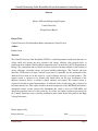
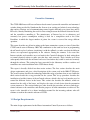
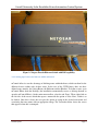
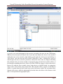
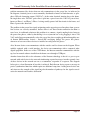
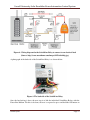
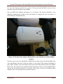
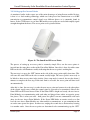
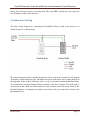
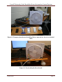
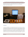
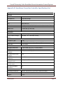
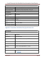
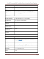
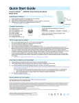
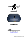
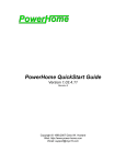
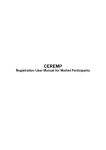
Cornell University Solar Decathlon House Automation Control System
Cornell University Solar Decathlon House Automation
Control System
A Design Project Report
Presented to the Engineering Division of the Graduate School
Of Cornell University
In Partial Fulfillment of the Requirements for the Degree of
Master of Engineering (Electrical)
By
Roshan Jacob
Project Advisor: Prof. Bruce Land
Degree Date: August, 2009
Roshan Jacob
Page 1
Cornell University Solar Decathlon House Automation Control System
Abstract
Master of Electrical Engineering Program
Cornell University
Design Project Report
Project Title:
Cornell University Solar Decathlon House Automation Control System
Author:
Roshan Jacob
Abstract:
The Cornell University Solar Decathlon (CUSD) is a multi-department student team that aims to
design, build and operate the most attractive and energy efficient solar-powered house to
compete in the bi-annual Solar Decathlon competition that is sponsored by the US Department of
Energy. The competition aims to educate and raise awareness amongst students of the benefits of
energy efficiency, renewable energy and green building technologies. The Controls sub team
under the CUSD aims to design a control system that is responsible for the automation of the
different devices that are in the house in a power efficient and easy to install manner. The
control system is expected to be flexible and should allow for the easy installation of the
different electrical devices to which it should interface and control. The control system is
expected to be able to control approximately 18 different devices in the house and is expected to
be robust and fail safe. This report describes the main components of the INSTEON based house
automation control system, provided by Smarthome Inc, which is used in CUSD 2009, and
details the procedure used to set the system up. As of date, the control system has been tested in
the Controls Laboratory and is awaiting installation in the actual house being built in the High
Voltage Laboratory.
Report Approved by
Project Advisor: ____________________
Roshan Jacob
Date: __________________
Page 2
Cornell University Solar Decathlon House Automation Control System
Table of Contents
Executive Summary....................................................................................................................................... 4
1.0 Design Requirements .............................................................................................................................. 4
2.0 Possible House automation solutions ..................................................................................................... 5
3.0 Design Process ........................................................................................................................................ 6
3.1 Setting up mControl and mPanels ...................................................................................................... 6
3.1.1 Setting up of zones and macros within mControl........................................................................ 8
3.1.2 Setting up the mPanels .............................................................................................................. 12
3.2 INSTEON Technology ........................................................................................................................ 13
3.2.1 INSTEON – What is it? ................................................................................................................ 13
3.2.2 INSTEON – How it works ............................................................................................................ 14
3.3 Setting up the SwitchLinc Relay and PowerLinc Modem .................................................................. 17
3.4 Setting up the Access Points ............................................................................................................. 21
4.0 Controls Laboratory Testing .................................................................................................................. 22
Conclusion ................................................................................................................................................... 24
References .................................................................................................................................................. 25
Appendix A: Smarthome Access Points Specifications ............................................................................... 26
Appendix B: Smarthome PowerLinc Controller Specifications List............................................................. 27
Appendix C: Smarthome SwitchLinc Relay Specifications List .................................................................... 28
Appendix D: mPanel Specifications List ...................................................................................................... 31
Roshan Jacob
Page 3
Cornell University Solar Decathlon House Automation Control System
Executive Summary
The CUSD 2009 house will have an Insteon based control system with controllers and automated
switches being provided by Smarthome Inc. Insteon is an exciting and relatively new technology
that employs a unique way of communicating control signals efficiently over power lines and by
RF waves, thereby eliminating the need for extra wiring between the different electrical devices
and the controllers controlling it. The attractiveness of Insteon lays in its robustness and
extremely low power consumption, making it ideal for a competition such as the Solar
Decathlon, in which the largest number of points for a team is reserved for energy efficient
operation.
This report describes my efforts in setting up the home automation system ever since I joined the
CUSD controls team in February 2009. My contribution to the team has been in programming
the mControl top level software, interfacing it with the mPanels, to make sure that the different
devices are represented appropriately in the software. During the summer, I also tested the
Insteon switches and controllers on a test bench in the Controls Laboratory by hard wiring them
to normal electrical sockets to make sure that they work correctly. These switches were then
subsequently linked with the mControl and tested on whether they could be activated remotely
through the software. This testing has been successful in the laboratory and these switches and
controllers now await installation in the CUSD house shortly.
This report is broadly divided into three main sections. The first section describes the main
design requirements and gives a brief description of the system used in the 2009 CUSD house.
The second section describes the technology behind the range of products that are used while the
third section details the set up procedure for the system. This set up procedure describes the
installation of and the features of the mControl software, which is the top level interface used to
control the different devices in the house. This section also describes the mPanels, which are
mounted on the walls of the house, and displays the status of each device that the automation
system connects to. The section further goes onto describe the procedure on how to link the mcontrol software to the controllers such that the purposes of home automation are achieved. The
report is also intended to be a future installation manual for the incoming students who will
continue to work in the controls sub team of CUSD.
1.0 Design Requirements
The main design requirements for the House Automation Control System are as follows:
Roshan Jacob
Page 4
Cornell University Solar Decathlon House Automation Control System
•
•
•
•
•
The system should be power efficient since this is the criterion that has the most number
of points allocated to it in the Solar Decathlon competition.
The system is expected to be easy to install and set up since installation of the system will
be amongst the last tasks that will be performed on the house and will be done so on a
tight timeline.
The system is also expected to be flexible and should interface easily with the different
devices that it is expected to control in the house.
The system should be responsive, robust, fail safe and capable of controlling both light
and heavy loads typically found in a house environment
The system is also expected to be cost efficient in terms of the controllers and the
automated switches used in it.
2.0 Possible House automation solutions
Many home automation solutions are available in the marketplace sold by mainstream companies
such as GE, Schneider Electric, etc. Amongst the different types available, the one that was
chosen for the CUSD 2009 house was that provided by Smarthome Inc. Smarthome Inc. markets
its brand of home automation solutions based on the patented Insteon technology and was
prepared to supply the CUSD team with its controllers and automated switches. For the top end
interface, software by the name mControl sold by Embedded Automation Inc. was chosen.
Embedded Automation agreed to provide its licensed software, which was compatible to the
Insteon devices of Smarthome, along with two mPanels which are to be mounted on the walls of
the CUSD house.
Amongst the different advantages that Smarthome Inc. had in comparison to its competitors, the
major one was that since their control system was based on Insteon technology, control signals
could be transmitted over power lines and over RF frequencies as will be detailed later in the
report, thereby eliminating the need to have separate wiring to just carry the control signals in the
house. Also, the system marketed by Smarthome met all of the major design requirements in
that it was extremely power efficient, on testing in the Controls Laboratory was found to be
robust, very easy to be set up, was easy to interface with any electrical device and was capable of
handling all loads that were expected to be in the CUSD house. The mControl software also
offered similar advantages in that it was fairly intuitive and easy to set up and had the capability
to interface with a whole host of controllers, Insteon just being one of them. It offered flexibility
in the sense that in the future, if it was decided that Insteon controllers were not to be used, the
top level software would require only minimal changes in its programming to make it compatible
with the new controllers. The cost of the system was not an issue since it was sponsored almost
entirely by these two firms.
Roshan Jacob
Page 5
Cornell University Solar Decathlon House Automation Control System
3.0 Design Process
This part of the report describes the design process in setting up the entire house automation
system. Firstly, the installation of the mControl software and its interfacing with the mPanels are
described. The report then goes on to describe what Insteon technology is and how it works. The
last section describes how to set up the automated switches, the Insteon controllers and the RF
Access points and also describes the procedure by which the three are linked to the mControl.
3.1 Setting up mControl and mPanels
As of 2009, the top level user interface software that is used to automate and control the different
devices within the CUSD house is mControl. The mControl software is made and released by the
firm Embedded Automation, Inc. mControl allows one to control all aspects of the home from
Media Center PC, locally or remotely via Internet Explorer browser or from a Windows Mobile
device. The installation of the mControl software on Windows is typical of most Windows
applications and is fairly intuitive. A detailed description of the installation procedure can be
obtained
from
the
online
user
manual
from
Embedded
Automation
(http://www.embeddedautomation.com/mControl%20v2%20(Home%20Edition)%20User%20M
anual.pdf).
In the house, the mControl software has been installed on a central home server from where it is
accessed by a central computer and then projected onto two television screens and the mPanels.
The mPanel is a portal to the CUSD house. It is a wall-mountable touch screen that allows one to
play digital music within the room and, by connecting to mControl, manage the home’s lighting
and climate settings, adjust security and surveillance systems and control other digital devices
within the home. As of 2009, the CUSD house will have two mPanels and two televisions, one
each in the bedroom and the kitchen of the house, which will show the status of the different
devices within the room. The mPanels communicate with the home server over Prosafe Ethernet
switch with Poe (Power over Ethernet). The photographs below show what the mPanel and the
Ethernet Switch look like. The mPanel, though operated via touchscreen, also has a USB port
which allows it to be operated via a wireless Logitech keyboard also shown in the photograph. A
complete data sheet of the m-panel has been attached in the Appendix.
Roshan Jacob
Page 6
Cornell University Solar Decathlon House Automation Control System
Figure 1: The mPanel and the Logitech wireless USB keyboard
The mPanel offers an additional advantage in that it can be powered over PoE (Power over
Ethernet) cables and does not need a dedicated power supply to operate, thereby saving an
additional set of wiring.
Roshan Jacob
Page 7
Cornell University Solar Decathlon House Automation Control System
Figure 2: Netgear Prosafe Ethernet Switch with PoE capability
3.1.1 Setting up of zones and macros within mControl
mControl offers its user the advantage of defining zones within the house, which can then list the
different devices within each of those zones. In the case of the CUSD house, there are three
defined zones namely, the Living Room, the Bedroom and the Kitchen. To define a zone, open
mControl Editor from the Desktop (the installation automatically creates a desktop shortcut to
open the mControl Editor). On the main menu toolbar, select the tab ‘Zone’. Then, right click on
the left side of the screen, which then opens a menu with the option of ‘New Zone’, which is to
be clicked. Once this is done, the user gets the option of typing in the desired zone name and
associating that zone name with an appropriate image. The screenshot below shows the screen
that appears when this is attempted:
Roshan Jacob
Page 8
Cornell University Solar Decathlon House Automation Control System
As can be seen in the background of the previous screenshot, the zones for the CUSD house
2009 have been already been defined. Once a zone has been defined, the devices to be controlled
within that zone can be entered by right clicking on the right side of the screen and clicking on
‘New Device’ once the zone has been selected. When this is done, a dialogue box opens up
which requires the user to enter five parameters, namely the device name, the adapter controlling
this particular device, the device module, an appropriate image for the device and the address of
the controller controlling that device. In the case of the CUSD, the adapter is always chosen to be
Insteon Ctrl with the device module always being chosen as On/Off Switch. An appropriate
image can be selected from a drop down menu. The controller address (in this case the Insteon
address) is gotten from the label on the lower end of the Insteon switch. The screenshot below
illustrates this process while the photograph below that shows the address of the Insteon switch
that is to be copied into the appropriate space.
Roshan Jacob
Page 9
Cornell University Solar Decathlon House Automation Control System
Roshan Jacob
Page 10
Cornell University Solar Decathlon House Automation Control System
Figure 3: The Insteon SwitchLinc Relay with its individual address circled at the bottom
Once the zones and devices are defined, macros can be created using simple If-Then commands
to switch certain combinations of devices on/off at certain times or for certain periods of time.
To define a new macro, select the ‘Automation’ tab from the main menu toolbar, right click on
the right hand side of the screen and select ‘New Macro’. Once this is done, the user is prompted
to enter a macro name, a macro image and is required to select the zone in which the macro is to
operate. After this is done, macros can be created by a simple drag and drop action. The
screenshot below illustrates this:
Roshan Jacob
Page 11
Cornell University Solar Decathlon House Automation Control System
3.1.2 Setting up the mPanels
The mPanels are set up fairly simply by connecting an Ethernet cable between the server and the
panel (In the case of the CUSD setup, this connection is done through an ethernet switch with
PoE capability). This connection is shown in the photograph below:
Roshan Jacob
Page 12
Cornell University Solar Decathlon House Automation Control System
Figure 4: The bottom of the mPanel where the Ethernet cable is to be connected
3.2 INSTEON Technology
As mentioned earlier in the report, CUSD 2009 has used SmartLabs, Inc. developed INSTEON
controllers to be able to automate the different devices within the house. Before I go on as to
how these controllers are set up in the house, I would like to briefly explain what this technology
is all about and how it works.
3.2.1 INSTEON – What is it?
Insteon is a patented technology which utilizes both normal power lines and Radio frequencies to
communicate control signals to everyday electric household devices, which otherwise normally
work independently. This technology was invented by SmartLabs, Inc. Insteon was developed,
based on the X10 model, for control and sensing applications in the home1. (X10 is an
international and open industry standard for communication among electronic devices used
for home automation, also known as domotics. It primarily uses power line wiring for signaling
and
control,
where
the
signals
involve
brief radio
frequency bursts
2
representing digital information. )
Roshan Jacob
Page 13
Cornell University Solar Decathlon House Automation Control System
All devices in an Insteon network are peers, meaning that each device can transmit, receive, and
repeat any message of the Insteon protocol, without requiring a master controller or complex
routing software. The main improvement that the Insteon has over the X10 protocol is that the
X10 does not have as powerful error checking as Insteon does because the control signal does
not get repeated by each unit in the system
According to Popular Mechanics' magazine article, Insteon is not only "an effective system for
connecting lighting switches and loads without extra wiring, but it also forms the basis for a
more sophisticated home automation network."
3.2.2 INSTEON – How it works
As mentioned earlier, Insteon transmits control signals over both power lines and over RF
frequency. It takes advantage of the fact that all households have electric wiring and of the fact
that ISM radio bands are available for free for unlicensed home use. The fact that both these
media are used is worth noting because transmission over just one could prove faulty and might
not always work. Power lines are known for their electrical noise which may prevent signals
from one half bridge electrical circuit to reach the other. Also, the home environment with its
many obstacles can cause instances where RF waves maybe reflected or easily attenuated. Thus
this dual signal transmission technology is what makes Insteon robust and fairly fault proof.
3.2.2.1 INSTEON Network Topology
The diagram below gives an overview of how a typical Insteon network functions:
Roshan Jacob
Page 14
Cornell University Solar Decathlon House Automation Control System
Figure 5: The Insteon network topology (Source: Diagram modified from
http://www.insteon.net/pdf/insteonthedetails.pdf)
As can be seen in the diagram, all Insteon devices that are plugged into the power line
communicate with each other through Insteon Powerline protocol. Insteon devices with radios
use radio frequency protocol to communicate with other Insteon devices that have radios.
The Insteon Powerline protocol is compatible with the X10 protocol, meaning that designers are
free to create Insteon devices that can also listen and talk to X10 devices. Insteon devices that
can use both the Insteon Powerline protocol and the Insteon RF protocol to solve a significant
Roshan Jacob
Page 15
Cornell University Solar Decathlon House Automation Control System
problem encountered by devices that can only communicate via the power line. As indicated in
the diagram, electrical power is most commonly distributed to homes in North America as splitphase 220-volt alternating current (220 VAC). At the main electrical junction box to the home,
the single three-wire 220 VAC power line is split into a pair of two-wire 110 VAC power lines,
known as Phase 1 and Phase 2. Phase 1 wiring usually powers half the circuits in the home, and
Phase 2 powers the other half.
The problem is that power line signals originating on the opposite power line phase from a power
line receiver are severely attenuated, because there is no direct circuit connection for them to
travel over. A traditional solution to this problem is to connect a signal coupling device between
the power line phases, either by hardwiring it in at a junction box or by plugging it into a 220
VAC outlet. Insteon automatically solves the power line phase coupling problem through the use
of Insteon RF/Powerline devices— Insteon RF messaging bridges the power line phases
whenever at least one of these devices is installed on each power line phase3.
Also, Insteon devices can communicate with the outside world as shown on the diagram. When
suitably equipped with a serial interface, the device can communicate with a computer/ other
digital equipment. In the case of the CUSD house, the Insteon controller communicates with the
top level m-control software installed on the home server through a USB port.
Another feature that adds to the robustness of the Insteon technology is that it is a peer to peer
network with each device in the network simulcasting repeated messages into the network. Any
of these devices in the network can act as a transmitter, responder or a repeater. The diagram
below gives a clear illustration of how this is achieved. Each Insteon device repeats a message in
precise synchronized timeslots which require no additional setup time. Adding more devices not
only increases the strength of the signal but also the number of pathways for the signal to travel
across the network and reach its destination4.
Roshan Jacob
Page 16
Cornell University Solar Decathlon House Automation Control System
Figure 6: A complete multi phase system being controlled by Insteon (Source:
http://www.insteon.net/pdf/insteonthedetails.pdf)
3.3 Setting up the SwitchLinc Relay and PowerLinc Modem
Of the different Insteon compatible devices available on the market, CUSD 2009 uses the
SwitchLinc V2 Relay (Model Number 2476S). The SwithLinc allows the user to install and
develop a robust home automation system while maintaining backwards compatibility with any
previously installed X10 devices.
This shallow-depth on/off wall switch is loaded with features as seen in the specifications sheet
attached in the Appendix. It allows the user to control any non-dimmable loads up to 13 amps
(480 Watts incandescent). The SwitchLinc Relay is controlled by an Insteon PowerLinc Modem
supplied to us by Smarthome Inc. The Serial Insteon PowerLinc Modem is a serial-based home
automation interface that allows PC- and hardware-based automation controllers to control
Roshan Jacob
Page 17
Cornell University Solar Decathlon House Automation Control System
Insteon -compatible lights, appliances, heating/air conditioning systems and alarm systems
directly via the Insteon network. This interface uses simple RS-232 commands, allowing any
device with a programmable serial port to send Insteon commands easily. The controller
connected to the Serial Insteon PowerLinc Modem must remain powered on and running the
controller program connected to the controller or host at all times of usage. The SmartLinc
modem is pictured below:
Figure 7: The Insteon PowerLinc Modem
This PowerLinc modem is to be switched on and then linked to the same phase as the one that is
connected to the various SwitchLinc Relays that are used to control the various devices. In the
house, all the SwitchLinc Relays are connected to normal electrical outlets which are then
connected to the different lights, fans and other devices. To setup the whole system, the
SwitchLinc Relay is to be hard wired to the electrical outlet. The wiring diagram that
accomplishes this is as shown below:
Roshan Jacob
Page 18
Cornell University Solar Decathlon House Automation Control System
Figure 8: Wiring diagram for the SwitchLinc Relay to connect to an electrical load
(Source: http://www.smarthome.com/images/2476sside4big.jpg)
A photograph of the backside of the SwitchLinc Relay is as shown below:
Figure 9: The backside of the SwitchLinc Relay
Once the hard wiring is done, the next step is to link the individual SwitchLinc Relays with the
PowerLinc Modem. For this to be done, the user is expected to press and hold the ON button on
Roshan Jacob
Page 19
Cornell University Solar Decathlon House Automation Control System
the side of the Insteon controller for a period of 10 seconds until the LED at the side of the
controller below the ON button starts blinking.
Once the LED starts blinking, this button is to be released. The Insteon Controller is now
officially in linking mode and the user has four minutes to complete the next step which is to
finish linking the SwitchLinc Relay.
Figure 10: The PowerLinc modem with the LED’s on the side that are used for linking
purposes
The next step is to press the SwitchLinc’s Paddle Top for about 10 seconds until the LED at the
sides start flashing. Once this is done the paddle is to be released. The stoppage of blinking of
these LED’s indicates successful linkage between the PowerLinc Modem and the SwitchLinc
Relay. Once this step has been completed and the appropriate address of the SwitchLinc Relay
entered into the mControl software as described in the earlier section, the SwitchLinc Relay
should be able to be controlled by the mControl software.
Roshan Jacob
Page 20
Cornell University Solar Decathlon House Automation Control System
3.4 Setting up the Access Points
As mentioned earlier in the report, one of the main advantages of using Insteon enabled devices
is that it is a dual meshing technology which uses both power line transmissions as well RF
transmission to communicate control signals over different phases as is commonly found in
houses. In the CUSD house, two of these RF enables access points are used which amplify signal
strength throughout the house. The access point used is pictured below:
Figure 11: The SmartLinc RF Access Points
The process of setting up an access point is extremely simple. First, one the access points is
inserted into the same phase as that of the PowerLinc Modem. Once this is done, the white status
LED on the side will illuminate steadily indicating that the access point is working fine.
The next step is to press the ‘SET’ button on the side of this access point rapidly four times. This
will cause the status LED on the side to remain steadily bright. The access point is now ready to
be linked to other access points in the vicinity. Once setup mode is entered, the user has about 9
minutes to complete the next step. If this time limit is exceeded, the access point will time itself
out automatically.
After this is done, the next step is to take the next access point and connect it to the other phase
of the electric supply across which the control signal is expected to be transmitted. Observe the
Status LED on the Second Access Point. If the Status LED is bright and steady, the two Access
Point Modules are communicating with each other and plugged into outlets on opposite power
line phases. This is what you want – both power line phases can now communicate with each
other via the two Access Point Modules. If the Status LED blinks or remains steady at a dim
level the two Access Point Modules are either unable to communicate, or can communicate but
are on the same power line phase. In either case, unplug the second Access Point and try locating
it to another outlet. Once the access points are determined to be communicating, tap the ‘SET’
Roshan Jacob
Page 21
Cornell University Solar Decathlon House Automation Control System
button of the first access point to exit setup mode. The status LED’s on both the access point will
now illuminate steadily at the dim level.
4.0 Laboratory Testing
The basic wiring diagram for connecting the SwitchLinc Relays found in the house to an
electrical outlet is as shown below:
The actual placement of these switches in the house can be seen in the electrical lay out diagram
of the house, which I helped design. The Electrical layout of the house can be found attached in
the Appendix. In the controls laboratory, I have set up a test bench in which SwitchLinc Relays
were connected to a normal electrical outlet according to the above diagram. Test loads such as
an electric fan and a bulb were then connected to the electrical outlet and turned on/off by the
mControl Software. A temporary test bench in two of these relays are connected is shown in the
photographs below:
Roshan Jacob
Page 22
Cornell University Solar Decathlon House Automation Control System
Figure 12: Temporary bench to test SwitchLinc Relays connected to a fan via an electrical
outlet
Figure 13: Circuit wiring for the test bench
Roshan Jacob
Page 23
Cornell University Solar Decathlon House Automation Control System
The figure below shows the entire setup with the mControl software, The Insteon controller, the
mPanel and the SwitchLinc relays. Each of the above has been set up according to the
procedures describes earlier in the report.
Figure 14: The entire controls setup
Conclusion
As of date, the SwitchLinc relays and the PowerLinc modem have been tested on a temporary
test bench that has been setup in the CUSD Controls Laboratory. All the SwitchLinc relays that
are expected to be installed on the house have been tested by first hard wiring them to electrical
sockets similar to the ones that are to be used in the house, then linking them to the PowerLinc
modem and the Access Points and then were remotely used to switch on/off test devices such as
a light bulb and a table fan. On testing, the Insteon controllers have been found to extremely
robust in the control aspect. The only fault that I could point out is that the LED’s on the side of
Roshan Jacob
Page 24
Cornell University Solar Decathlon House Automation Control System
the SwitchLinc paddles seem to have a very short life. The relay as such works perfectly, but the
failure of the LED’s can cause some confusion when trying to link it to the PowerLinc modem.
References
1.
2.
3.
4.
http://www.insteon.net/about-howitworks.html
http://en.wikipedia.org/wiki/X10_(industry_standard)
http://www.smartlabsinc.com/files/INSTEONCompared20060102a.pdf
http://www.insteon.net/pdf/insteonthedetails.pdf
Roshan Jacob
Page 25
Cornell University Solar Decathlon House Automation Control System
Appendix A: Smarthome Access Points Specifications
Specifications
Brand:
Smarthome
Manufacturer:
SmartLabs Design
Manufacturer Product
No.:
2443
UPC:
689076406840
Patent No.:
U.S. Patent No. 7,345,998, International patents pending
Dimensions:
3 7/8" x 1 1/2" x 2 7/16"
Frequency:
915 MHz
RF Range:
200 feet, line of sight
Status LED:
Yes
Available Modes:
INSTEON only
FCC ID:
SBP2443
Warranty:
2 years, limited
INSTEON Features
INSTEON Powerline
Frequency:
131.65 KHz
Radio Frequency:
915 MHz
INSTEON Messages
Repeated:
Yes
Mechanical
Operating Conditions:
Indoors, 0 to 70°C, up to 85% relative humidity
Dimensions:
3 7/8" x 1 1/2" x 2 7/16"
Weight:
3.6 oz.
Electrical
Supply Voltage:
120 Volts AC +/- 10%, 60 Hertz, single phase
Voltage & Frequency:
120 Volts AC +/- 10%, 60 Hertz, single phase
Surge Protection:
MOV rated for 150 Volts
Certification:
Safety tested for use in USA and Canada (ETL #3017581)
FCC ID:
SBP2443
X10 Features
X10 Messages Repeated: No
Roshan Jacob
Page 26
Cornell University Solar Decathlon House Automation Control System
Appendix B: Smarthome PowerLinc Controller Specifications List
Specifications
General
Brand:
Smarthome
Manufacturer:
SmartLabs Design
Manufacturer Product
No.:
2412s
UPC:
689076403047
Patent No.:
U.S. Patent No. 7,345,998, International patents pending
Software:
Sold Separately
Status LED:
1 white LED (on the side)
Warranty:
2 years, limited
Operation
Operation Modes:
INSTEON only, X10 only, INSTEON and X10 Combo Mode
Combo Mode Message
Order:
INSTEON, X10, INSTEON cleanup
Interface
Connector Type:
RJ-45
Interface:
RS-232 & TTL & 12VDC (unregulated) @300mA
Baud Rate:
19,200 Kbps
INSTEON Features
INSTEON Addresses:
1 hard-coded out of 16,777,216 possible
INSTEON Links:
2016 out of 16,777,216 possible
INSTEON Device
Category:
0x03 (Network Bridges)
INSTEON Device SubCategory:
0x05
INSTEON Power Line
Frequency
131.65 KHz
INSTEON Minimum
Transmit Level:
3.2 Vpp into 5 Ohms
INSTEON Minimum
Receive Level:
10 mV
INSTEON Messages
Repeated:
Yes
Mechanical
Operating Conditions:
Indoors, 40 to 132ºF, up to 85% relative humidity
Dimensions:
3.9" H x 2.6" W x 1.5" D
Weight:
9.6 oz
Roshan Jacob
Page 27
Cornell University Solar Decathlon House Automation Control System
Electrical
Supply Voltage:
120 Volts AC +/- 10%, 60 Hertz, single phase
Surge Protection:
MOV rated for 150 Volts
Pass-Through Outlet:
Uncontrolled 3-prong (with ground), 120V, 15A
Certification:
Safety tested for use in USA and Canada (ETL #3017581)
X10 Features
X10 Scene Addresses:
255 possible
X10 Controllable
Addresses:
255 possible
X10 Status Response:
supported
X10 Resume Dim:
supported
X10 Powerline Frequency: 120 KHz
X10 Minimum Transmit
Level:
3.2 Vpp into 5 Ohms
X10 Minimum Receive
Level:
20mV into 5 Ohms
X10 Messages Repeated: No
Appendix C: Smarthome SwitchLinc Relay Specifications List
Specifications
General
Brand:
Smarthome
Manufacturer
SmartLabs Design
Manufacturer Product
No.:
2476S, INSTEON Non-Dimming INSTEON SwitchLinc Relay
UPC:
891114000099
Patent No.:
U.S. Patent No. 7,345,998, International patents pending
Warranty:
2 years, limited (Upgradeable to 7 years)
Operation
LED Indicator:
Roshan Jacob
8 White LEDs, Optional Green, Blue, Amber, or Red
with#2400L kit
Page 28
Cornell University Solar Decathlon House Automation Control System
Operation Modes:
INSTEON only, X10 only, INSTEON and X10 Combo Mode
Combo Mode Message
Order:
INSTEON, X10, INSTEON cleanup
Multi-Way Circuit
Support:
One SwitchLinc Dimmer controls load, Cross-Link any
number of SwitchLinc Relays or other INSTEON Controllers
Setup Memory:
Non-volatile EEPROM
INSTEON Features
INSTEON Addresses:
1 hard-coded out of 16,777,216 possible
INSTEON Links:
417 out of 16,777,216 possible
INSTEON Powerline
Frequency:
131.65 KHz
INSTEON Minimum
Transmit Level:
3.2 Vpp into 5 Ohms
INSTEON Minimum
Receive Level:
10 mV
INSTEON Messages
Repeated:
Yes
Mechanical
Paddle Type:
True rocker action
Color:
White installed; Optional Ivory, Almond, Black, Brown, or
Gray with #2400xx kits
Wire Nuts:
3 included
Mounting:
Mounts in single or multiple-ganged junction box
Operating Conditions:
Indoors, 40 to 104°F, up to 85% relative humidity
Dimensions:
4.1" H x 1.8" W x 1.2" D
Weight:
3.6 oz
Roshan Jacob
Page 29
Cornell University Solar Decathlon House Automation Control System
Electrical
Supply Voltage:
120 Volts AC +/- 10%, 60 Hertz, single phase
Surge Protection:
MOV rated for 150 Volts
Power Wire Leads:
6", 16 AWG, stranded, 600V, 105°C insulation, ends stripped
and tinned, LINE (black), LOAD (red), NEUTRAL (white)
Ground Lead:
6", 18 AWG, stranded, bare copper
Load Types:
Wired-in incandescent lighting and inductive loads
Neutral Wire:
Required
Maximum Load:
15 Amps; 480 Watts (for incandescent loads)
Minimum Load:
No minimum load required
Certification:
Safety tested for use in USA and Canada (ETL #3017581)
X10 Features
X10 Primary Address:
1 optional (comes unassigned)
X10 Scene Addresses:
255 possible
X10 Status Response:
Supported
X10 Resume Dim:
Supported (by setting Local On-Level to zero)
X10 Powerline Frequency: 120 KHz
X10 Minimum Transmit
Level:
3.2 Vpp into 5 Ohms
X10 Minimum Receive
Level:
20mV into 5 Ohms
X10 Messages Repeated: No
Roshan Jacob
Page 30
Cornell University Solar Decathlon House Automation Control System
Appendix D: mPanel Specifications List
•
•
•
•
•
•
•
•
•
•
•
•
•
•
•
•
•
•
ARM9 800MHz, 1GB Flash, Windows CE 6.0
7” TFT LCD (800 x 480) with 4-wire touch
Power over Ethernet [802.3AF Powered Device] (DC Power connector available for nonPoE applications)
Line in [stereo]
USB connectors [Host and Client]
Ethernet RJ-45 10/100BaseT
Serial RJ-11 [RS-232]
On-board audio amplifier. Speakers connect via 4-pin Phoenix connector [mating plug
provided]
2 x 20W Output Power in Stereo Mode (8Ω, THD = 10%)
20W/ch with 19.5V external supply
15W/ch with dual channel PoE
High Efficiency: Up to 87%
Line Gain +22dB.
High PSRR (90dB at 1kHz)
Shutdown and Mute Control
Full differential output
Thermal Protection
mPanel software - Plays networked media [supports all Windows Media Player 10
formats and playlists]. Auto-discover mControl automation servers for home device
status and control. mControl supports lighting systems, security panels, thermostats,
cameras and more.
Roshan Jacob
Page 31