1
RCC-02/-03 Quick guide
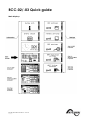
Main displays
Studer Innotec SA 2013 – V 4.2.1
4O9C7
Studer Innotec SA
Quickguide RCC-02/-03
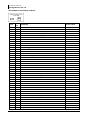
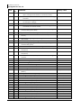
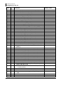
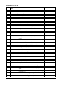
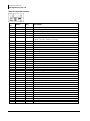
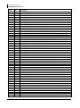
ADJUSTMENT OF THE REMOTE CONTROL
Level
Basic
Expert
Basic
Basic
Basic
Basic
Basic
V.O.
Expert
Expert
Expert
Expert
Inst.
Basic
Basic
Basic
Basic
Expert
Expert
Expert
Expert
Expert
Expert
Inst.
Expert
Expert
Expert
Expert
Inst.
Expert
Expert
Expert
Expert
Expert
Inst.
Expert
Expert
Expert
Expert
Inst.
Expert
2
User
ref.
5000
5036
5038
5039
5040
5001
5002
5012
5019
5057
5101
5059
5120
5013
5041
5068
5070
5032
5069
5030
5049
5015
5016
5097
5098
5050
5017
5018
5033
5034
5045
5051
5052
5053
5054
5055
5084
5085
5086
5087
5088
Parameter
Factory value
Language
OTHER LANGUAGES
Choice of the second language
Choice of the third language
Choice of the fourth language
Time
Date
User level
Force remote control to user BASIC level
DATALOGGER
Datalogger enabled
Save today's datas
Erase the 30 oldest log files from the SD card
SAVE AND RESTORE FILES
Save all files (system backup)
Restore all files (system recovery)
Apply configuration files (masterfile)
Separator of the .csv files
Advanced backup functions
Save messages
Save and restore RCC files
Save RCC parameters
Load RCC parameters
Create RCC configuration file (masterfile)
Load RCC configuration file (masterfile)
Save and restore Xtender files
Save Xtender parameters
Load Xtender parameters
Create Xtender configuration file (masterfile)
Load Xtender configuration file (masterfile)
Load Xtender parameters preset
Save and restore BSP files
Save BSP parameters
Load BSP parameters
Create BSP configuration file (masterfile)
Load BSP configuration file (masterfile)
Save and restore VarioTrack files
Save VarioTrack parameters
Load VarioTrack parameters
Create VarioTrack configuration file (masterfile)
Load VarioTrack configuration file (masterfile)
0 English
V 4.2.1
French
German
Spanish
00:00
0
16
Automatic
Automatic
1
User manual
Studer Innotec SA
Quickguide RCC-02/-03
Level
Expert
Expert
Expert
Inst.
Expert
Inst.
Expert
Inst.
Inst.
Inst.
Basic
Basic
Basic
Expert
Basic
Basic
Expert
Expert
Expert
Basic
Expert
Expert
Inst.
Expert
Expert
Inst.
Inst.
Inst.
User
ref.
5063
5064
5065
5066
5067
5047
5061
5042
5043
5044
5007
5093
5009
5026
5021
5006
5073
5010
5011
5027
5031
5056
5071
5094
5105
5119
5095
5096
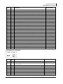
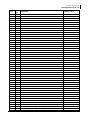
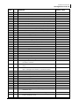
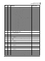
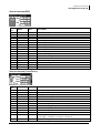
Parameter
Factory value
Save and restore MPPT Tristar files
Save MPPT Tristar parameters
Load MPPT Tristar parameters
Create MPPT Tristar configuration file (masterfile)
Load MPPT Tristar configuration file (masterfile)
Format the SD card
Start update
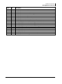
MODIFICATION OF ACCESS LEVELS OF MANY PARAMETERS
Change all parameters access level to:
Restore default access level of all parameters
BACKLIGHT
Backlight mode
Backlight switch off after
Red backlight flashing on Xtender off and faulty
EXTENDED AND SPECIAL FUNCTIONS
Display contrast
Choice of standard display
Come back to standard display after
Visibility of the transitory messages
Acoustic alarm active
Remote control acoustic alarm duration
Switching ON and OFF of system on level "VIEW ONLY"
Reset of all the remotes control
SCOM
Test of the modem's GPRS signal level
Device identification (LEDs) with the SCOM address
SCOM watchdog enable
Delay before Xcom-232i reset
Choose
Delayed
120 sec
Yes
55%
Xtender
600 sec
60 sec
Yes
120 sec
Yes
0
No
60 sec
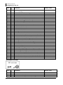
ADJUSTMENT OF THE XTENDER
Basic
Basic
User
ref.
1100
1551
Basic
Basic
Basic
Basic
Basic
Basic
Basic
1107
1138
1126
1124
1552
1187
1395
Level
User manual
Parameter
Factory value
BASIC SETTINGS
Basic parameters set by means of the potentiomenter
in the XTS
Yes
Maximum current of AC source (Input limit)
Battery charge current
Smart-Boost allowed
Inverter allowed
Type of detection of the grid loss (AC-In)
Standby level
Restore default settings
V 4.2.1
32 Aac
60 Adc
Yes
Yes
Tolerant
10%
3
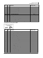
Studer Innotec SA
Quickguide RCC-02/-03
Inst.
Expert
Expert
Basic
Expert
Expert
Expert
Expert
Expert
Expert
Expert
Expert
Expert
Expert
Expert
Expert
Expert
Expert
Expert
Expert
Expert
Expert
Expert
Inst.
User
ref.
1287
1137
1125
1138
1139
1568
1108
1531
1191
1532
1109
1190
1110
1194
1195
1307
1298
1121
1122
1140
1467
1141
1142
1608
Expert
Expert
1143
1144
Voltage level 1 to start a new cycle
Time period under voltage level 1 to start a new
cycle
12.5/25/49.9 Vdc
30 min
Expert
Expert
1145
1146
Voltage level 2 to start a new cycle
Time period under voltage level 2 to start a new
cycle
12.3/24.6/49.2 Vdc
60 sec
Expert
1149
New cycle priority on absorption and equalization
phases
No
Expert
Expert
Expert
Expert
Expert
Expert
Expert
Expert
Expert
Expert
Expert
Expert
Expert
Expert
Expert
1147
1148
1451
1155
1156
1157
1158
1159
1160
1161
1452
1163
1162
1291
1290
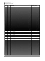
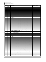
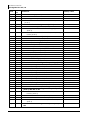
Level
4
Parameter
Factory value
Restore factory settings
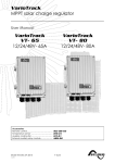
BATTERY MANAGEMENT AND CYCLE
Charger allowed
Battery charge current
Temperature compensation
Undervoltage
Battery undervoltage level without load
Battery undervoltage dynamic compensation
Battery undervoltage dynamic compensation
Kind of dynamic compensation
Battery undervoltage level at full load
Battery undervoltage duration before turn off
Restart voltage after batteries undervoltage
Battery adaptive low voltage (B.L.O)
Max voltage for adaptive low voltage
Reset voltage for adaptive correction
Increment step of the adaptive low voltage
Battery overvoltage level
Restart voltage level after an battery overvoltage
Floating voltage
Force phase of floating
New cycle menu
Force a new cycle
Use dynamic compensation of battery level (new
cycle)
-
Cycling restricted
Minimal delay between cycles
Absorption phase
Absorption phase allowed
Absorption voltage
Absorption duration
End of absorption triggered with current
Current limit to quit the absorption phase
Maximal frequency of absorption control
Minimal delay since last absorption
Equalization phase
Equalization allowed
Force equalization
Equalization before absorption phase
Equalization current
V 4.2.1
Yes
60 Adc
-3 mV/°C/cell
11.6/23.2/46.3 Vdc
Yes
Automatic
10.5/21/42 Vdc
3 min
12/24/48 Vdc
No
12.5/25/49.9 Vdc
13.2/26.4/52.8 Vdc
0.1/0.2/0.5 Vdc
17/34.1/68.2 Vdc
16.2/32.4/64.8 Vdc
13.6/27.2/54.4 Vdc
No
No
3 hours
Yes
14.4/28.8/57.6 Vdc
2 hours
No
4 Adc
No
2 hours
No
Yes
60 Adc
User manual
Studer Innotec SA
Quickguide RCC-02/-03
Expert
Expert
Expert
Expert
Expert
Expert
Expert
Expert
Expert
Expert
Expert
Expert
Expert
Expert
Expert
User
ref.
1164
1165
1166
1284
1285
1168
1169
1453
1170
1171
1172
1454
1173
1174
1175
Expert
Expert
Basic
Expert
Expert
Expert
Expert
Expert
Expert
1176
1186
1124
1286
1548
1560
1112
1536
1549
Periodic absorption duration
INVERTER
Inverter allowed
AC Output voltage
AC voltage increase according to battery voltage
Max AC voltage increase with battery voltage
Inverter frequency
Inverter frequency increase when battery full
Inverter frequency increase according to battery
voltage
Expert
Expert
1546
1534
Max frequency increase
Speed of voltage or frequency change in function of
battery
Expert
Basic
Expert
Expert
Expert
Expert
Expert
Expert
Expert
Basic
Inst.
Basic
Expert
Expert
1420
1187
1189
1188
1599
1438
1197
1128
1580
1126
1607
1107
1471
1566
Standby and turn on
Standby level
Time delay between standby pulses
Standby number of pulses
Softstart duration
Solsafe presence Energy source at AC-Out side
AC-IN AND TRANSFER
Transfer relay allowed
Delay before closing transfer relay
Smart-Boost allowed
Limitation of the power Boost
Maximum current of AC source (Input limit)
Max input current modification
Using a secondary value for the maximum current
of the AC source
Expert
1567
Second maximum current of the AC source (Input
limit)
16 Aac
Expert
1527
Decrease max input limit current with AC-In
voltage
No
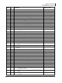
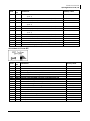
Level
User manual
Parameter
Factory value
Equalization voltage
Equalization duration
Number of cycles before an equalization
Equalization with fixed interval
Weeks between equalizations
End of equalization triggered with current
Current threshold to end equalization phase
Reduced floating phase
Reduced floating allowed
Floating duration before reduced floating
Reduced floating voltage
Periodic absorption phase
Periodic absorption allowed
Periodic absorption voltage
Reduced floating duration before periodic
absorption
V 4.2.1
15.6/31.2/62.4 Vdc
0.5 hours
25
No
26 weeks
No
4 Adc
No
1 days
13.2/26.4/52.8 Vdc
No
14.4/28.8/57.6 Vdc
7 days
0.5 hours
Yes
230 Vac
No
10 Vac
50 Hz
No
No
4 Hz
0
10%
0.8 sec
1
0 sec
No
Yes
0 min
Yes
100%
32 Aac
No
5
Studer Innotec SA
Quickguide RCC-02/-03
Expert
User
ref.
1554
Expert
Level
6
Parameter
Factory value
Decrease of the max. current of the source with
input voltage activated by command entry
No
1309
AC input low limit voltage to allow charger
function
180 Vac
Expert
1433
Adaptation range of the input current according
to the input voltage
10 Vac
Expert
Expert
1553
1295
Speed of input limit increase
Charge current decrease coef. at voltage limit to
turn back in inverter mode
50
100%
Expert
1436
Overrun AC source current limit without opening the
transfer relay (Input limit)
Yes
Basic
Expert
1552
1510
Type of detection of the grid loss (AC-In)
Tolerance on detection of AC-input loss (tolerant UPS
mode)
Tolerant
100
Expert
1199
Input voltage giving an opening of the transfer relay
with delay
180 Vac
Expert
Expert
1198
1200
Time delay before opening of transfer relay
Input voltage giving an immediate opening of the
transfer relay (UPS)
8 sec
90 Vac
Inst.
Expert
1432
1505
Absolute max limit for input voltage
Delta frequency allowed above the standard input
frequency
270 Vac
35 Hz
Expert
1506
Delta frequency allowed under the standard input
frequency
15 Hz
Expert
1507
Duration with frequency error before opening the
transfer
5 sec
Expert
Inst.
Inst.
Inst.
Expert
Expert
Expert
1575
1557
1559
1604
1201
1202
1497
AC-IN current active filtering
Use an energy quota on AC-input
AC-in energy quota
External transfert management
AUXILIARY CONTACT 1
Operating mode (AUX 1)
Combination of the events for the auxiliary contact
(AUX 1)
Expert
Expert
Expert
Expert
Expert
Expert
Expert
Expert
Expert
Expert
Expert
Expert
Expert
Inst.
1203
1204
1205
1206
1207
1208
1209
1210
1211
1212
1213
1214
1215
1216
Temporal restrictions (AUX 1)
Program 1 (AUX 1)
Day of the week (AUX 1)
Start hour (AUX 1)
End hour (AUX 1)
Program 2 (AUX 1)
Day of the week (AUX 1)
Start hour (AUX 1)
End hour (AUX 1)
Program 3 (AUX 1)
Day of the week (AUX 1)
Start hour (AUX 1)
End hour (AUX 1)
Program 4 (AUX 1)
V 4.2.1
No
No
1 kWh
No
Automatic
Any (Function OR)
None days
07:00 hh:mm
20:00 hh:mm
None days
07:00 hh:mm
20:00 hh:mm
None days
07:00 hh:mm
20:00 hh:mm
User manual
Studer Innotec SA
Quickguide RCC-02/-03
Level
Inst.
Inst.
Inst.
Inst.
Inst.
Inst.
Inst.
Expert
Expert
Expert
Expert
Expert
Expert
Expert
Expert
Expert
Expert
Expert
Expert
Expert
Expert
Expert
Expert
Expert
Expert
Expert
Expert
Expert
Expert
Expert
Expert
Expert
Expert
Expert
Expert
Expert
Expert
Expert
Expert
Expert
Expert
Expert
Inst.
Expert
Expert
Expert
Expert
Expert
User
ref.
1217
1218
1219
1220
1221
1222
1223
1269
1270
1271
1272
1273
1274
1275
1276
1277
1278
1279
1280
1281
1455
1225
1518
1543
1226
1227
1228
1229
1520
1231
1232
1233
1234
1235
1236
1237
1238
1239
1240
1242
1243
1244
1601
1245
1288
1246
1247
1248
User manual
Parameter
Factory value
Day of the week (AUX 1)
Start hour (AUX 1)
End hour (AUX 1)
Program 5 (AUX 1)
Day of the week (AUX 1)
Start hour (AUX 1)
End hour (AUX 1)
Contact active with a fixed time schedule (AUX 1)
Program 1 (AUX 1)
Day of the week (AUX 1)
Start hour (AUX 1)
End hour (AUX 1)
Program 2 (AUX 1)
Day of the week (AUX 1)
Start hour (AUX 1)
End hour (AUX 1)
Program 3 (AUX 1)
Day of the week (AUX 1)
Start hour (AUX 1)
End hour (AUX 1)
Contact active on event (AUX 1)
Xtender is OFF (AUX 1)
Xtender ON (AUX 1)
Remote entry (AUX 1)
Battery undervoltage alarm (AUX 1)
Battery overvoltage (AUX 1)
Inverter or Smart- Boost overload (AUX 1)
Overtemperature (AUX 1)
No overtemperature (AUX 1)
Active charger (AUX 1)
Active inverter (AUX 1)
Active Smart-Boost (AUX 1)
AC input presence but with fault (AUX 1)
AC input presence (AUX 1)
Transfer relay ON (AUX 1)
AC out presence (AUX 1)
Bulk charge phase (AUX 1)
Absorption phase (AUX 1)
Equalization phase (AUX 1)
Floating (AUX 1)
Reduced floating (AUX 1)
Periodic absorption (AUX 1)
AC-in energy quota (AUX1)
Contact active according to battery voltage (AUX 1)
Use dynamic compensation of battery level (AUX 1)
Battery voltage 1 activate (AUX 1)
Battery voltage 1 (AUX 1)
Delay 1 (AUX 1)
V 4.2.1
None days
07:00 hh:mm
20:00 hh:mm
None days
07:00 hh:mm
20:00 hh:mm
None days
07:00 hh:mm
20:00 hh:mm
None days
07:00 hh:mm
20:00 hh:mm
None days
07:00 hh:mm
20:00 hh:mm
No
No
No
No
No
No
No
No
No
No
No
No
No
No
No
No
No
No
No
No
No
No
Yes
Yes
11.7/23.4/46.8 Vdc
1 min
7
Studer Innotec SA
Quickguide RCC-02/-03
Expert
Expert
Expert
Expert
Expert
Expert
Expert
Expert
Expert
Expert
User
ref.
1249
1250
1251
1252
1253
1254
1255
1256
1516
1257
Expert
Expert
Expert
Expert
Expert
Expert
Expert
Expert
Expert
Expert
Expert
Inst.
1258
1259
1260
1261
1262
1263
1264
1265
1266
1267
1268
1503
Inst.
1446
Inst.
Inst.
Expert
1447
1448
1501
Expert
Expert
Expert
Expert
Expert
Expert
Expert
1439
1440
1581
1582
1583
1584
1585
Expert
Expert
Expert
Expert
Expert
Expert
Expert
Expert
Expert
Expert
1586
1587
1441
1588
1589
1512
1514
1569
1310
1311
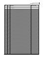
Level
8
Parameter
Factory value
Battery voltage 2 activate (AUX 1)
Battery voltage 2 (AUX 1)
Delay 2 (AUX 1)
Battery voltage 3 activate (AUX 1)
Battery voltage 3 (AUX 1)
Delay 3 (AUX 1)
Battery voltage to deactivate (AUX 1)
Delay to deactivate (AUX 1)
Deactivate if battery in floating phase (AUX 1)
Contact active with inverter power or Smart-Boost
(AUX 1)
Inverter power level 1 activate (AUX 1)
Power level 1 (AUX 1)
Time delay 1 (AUX 1)
Inverter power level 2 activate (AUX 1)
Power level 2 (AUX 1)
Time delay 2 (AUX 1)
Inverter power level 3 activate (AUX 1)
Power level 3 (AUX 1)
Time delay 3 (AUX 1)
Inverter power level to deactivate (AUX 1)
Time delay to deactivate (AUX 1)
Contact active according to battery temperature
(AUX 1) With BSP or BTS
Contact activated with the temperature of
battery (AUX 1)
Contact activated over (AUX 1)
Contact deactivated below (AUX 1)
Contact active according to SOC (AUX 1) Only with
BSP
Contact activated with the SOC 1 of battery (AUX 1)
Contact activated below SOC 1 (AUX 1)
Delay 1 (AUX 1)
Contact activated with the SOC 2 of battery (AUX 1)
Contact activated below SOC 2 (AUX 1)
Delay 2 (AUX 1)
Contact activated with the SOC 3 of battery (AUX 1)
Contact activated below SOC 3 (AUX 1)
Delay 3 (AUX 1)
Contact deactivated over SOC (AUX 1)
Delay to deactivate (AUX 1)
Deactivate if battery in floating phase (AUX 1)
Security, maximum time of contact (AUX 1)
Maximum time of operation of contact (AUX 1)
Reset all settings (AUX 1)
AUXILIARY CONTACT 2
Operating mode (AUX 2)
V 4.2.1
Yes
11.9/23.9/47.8 Vdc
10 min
Yes
12.1/24.2/48.5 Vdc
60 min
13.5/27/54 Vdc
60 min
Yes
No
120 % Pnom
1 min
No
80 % Pnom
5 min
No
50 % Pnom
30 min
40 % Pnom
5 min
No
3 °C
5 °C
No
50 % SOC
12 h
No
30%
0.2 h
No
20%
0h
90 % SOC
0.2 h
Yes
No
600 min
Reversed
automatic
User manual
Studer Innotec SA
Quickguide RCC-02/-03
Expert
User
ref.
1498
Expert
Expert
Expert
Expert
Expert
Expert
Expert
Expert
Expert
Expert
Expert
Expert
Expert
Inst.
Inst.
Inst.
Inst.
Inst.
Inst.
Inst.
Inst.
Expert
Expert
Expert
Expert
Expert
Expert
Expert
Expert
Expert
Expert
Expert
Expert
Expert
Expert
Expert
Expert
Expert
Expert
Expert
Expert
Expert
Expert
Expert
Expert
Expert
1312
1313
1314
1315
1316
1317
1318
1319
1320
1321
1322
1323
1324
1325
1326
1327
1328
1329
1330
1331
1332
1378
1379
1380
1381
1382
1383
1384
1385
1386
1387
1388
1389
1390
1456
1333
1519
1544
1334
1335
1336
1337
1521
1339
1340
1341
Level
User manual
Parameter
Factory value
Combination of the events for the auxiliary contact
(AUX 2)
Temporal restrictions (AUX 2)
Program 1 (AUX 2)
Day of the week (AUX 2)
Start hour (AUX 2)
End hour (AUX 2)
Program 2 (AUX 2)
Day of the week (AUX 2)
Start hour (AUX 2)
End hour (AUX 2)
Program 3 (AUX 2)
Day of the week (AUX 2)
Start hour (AUX 2)
End hour (AUX 2)
Program 4 (AUX 2)
Day of the week (AUX 2)
Start hour (AUX 2)
End hour (AUX 2)
Program 5 (AUX 2)
Day of the week (AUX 2)
Start hour (AUX 2)
End hour (AUX 2)
Contact active with a fixed time schedule (AUX 2)
Program 1 (AUX 2)
Day of the week (AUX 2)
Start hour (AUX 2)
End hour (AUX 2)
Program 2 (AUX 2)
Day of the week (AUX 2)
Start hour (AUX 2)
End hour (AUX 2)
Program 3 (AUX 2)
Day of the week (AUX 2)
Start hour (AUX 2)
End hour (AUX 2)
Contact active on event (AUX 2)
Xtender is OFF (AUX 2)
Xtender ON (AUX 2)
Remote entry (AUX 2)
Battery undervoltage alarm (AUX 2)
Battery overvoltage (AUX 2)
Inverter or Smart-Boost overload (AUX 2)
Overtemperature (AUX 2)
No overtemperature (AUX 2)
Active charger (AUX 2)
Active inverter (AUX 2)
Active Smart-Boost (AUX 2)
V 4.2.1
Any (Function OR)
None days
07:00 hh:mm
20:00 hh:mm
None days
07:00 hh:mm
20:00 hh:mm
None days
07:00 hh:mm
20:00 hh:mm
None days
07:00 hh:mm
20:00 hh:mm
None days
07:00 hh:mm
20:00 hh:mm
None days
07:00 hh:mm
20:00 hh:mm
None days
07:00 hh:mm
20:00 hh:mm
None days
07:00 hh:mm
20:00 hh:mm
Yes
No
No
Yes
Yes
Yes
Yes
No
No
No
No
9
Studer Innotec SA
Quickguide RCC-02/-03
Expert
Expert
Expert
Expert
Expert
Expert
Expert
Expert
Expert
Expert
Inst.
Expert
Expert
Expert
Expert
Expert
Expert
Expert
Expert
Expert
Expert
Expert
Expert
Expert
Expert
Expert
User
ref.
1342
1343
1344
1345
1346
1347
1348
1350
1351
1352
1602
1353
1354
1355
1356
1357
1358
1359
1360
1361
1362
1363
1364
1365
1517
1366
Expert
Expert
Expert
Expert
Expert
Expert
Expert
Expert
Expert
Expert
Expert
Inst.
1367
1368
1369
1370
1371
1372
1373
1374
1375
1376
1377
1504
Inst.
1457
Inst.
Inst.
Expert
1458
1459
1502
Expert
1442
Expert
1443
Level
10
Parameter
Factory value
AC input presence but with fault (AUX 2)
AC input presence (AUX 2)
Transfer contact ON (AUX 2)
AC out presence (AUX 2)
Bulk charge phase (AUX 2)
Absorption phase (AUX 2)
Equalization phase (AUX 2)
Floating (AUX 2)
Reduced floating (AUX 2)
Periodic absorption (AUX 2)
AC-in energy quota (AUX2)
Contact active according to battery voltage (AUX 2)
Use dynamic compensation of battery level (AUX 2)
Battery voltage 1 activate (AUX 2)
Battery voltage 1 (AUX 2)
Delay 1 (AUX 2)
Battery voltage 2 activate (AUX 2)
Battery voltage 2 (AUX 2)
Delay 2 (AUX 2)
Battery voltage 3 activate (AUX 2)
Battery voltage 3 (AUX 2)
Delay 3 (AUX 2)
Battery voltage to deactivate (AUX 2)
Delay to deactivate (AUX 2)
Deactivate if battery in floating phase (AUX 2)
Contact active with inverter power or Smart-Boost
(AUX 2)
Inverter power level 1 activate (AUX 2)
Power level 1 (AUX 2)
Time delay 1 (AUX 2)
Inverter power level 2 activate (AUX 2)
Power level 2 (AUX 2)
Time delay 2 (AUX 2)
Inverter power level 3 activate (AUX 2)
Power level 3 (AUX 2)
Time delay 3 (AUX 2)
Inverter power level to deactivate (AUX 2)
Time delay to deactivate (AUX 2)
Contact active according to battery temperature
(AUX 2) With BSP or BTS
Contact activated with the temperature of
battery (AUX 2)
No
No
No
No
No
No
No
No
No
No
No
Contact activated over (AUX 2)
Contact deactivated below (AUX 2)
Contact active according to SOC (AUX 2) Only with
BSP
Contact activated with the SOC 1 of battery (AUX 2)
3 °C
5 °C
Contact activated below SOC 1 (AUX 2)
V 4.2.1
No
No
12/24/48 Vdc
5 min
No
11.5/23/46.1 Vdc
5 min
No
11/22.1/44.2 Vdc
5 min
12.6/25.2/50.4 Vdc
5 min
No
No
120 % Pnom
0 min
No
80 % Pnom
5 min
No
50 % Pnom
30 min
40 % Pnom
5 min
No
No
50 % SOC
User manual
Studer Innotec SA
Quickguide RCC-02/-03
Expert
Expert
User
ref.
1590
1591
Expert
Expert
Expert
Expert
Expert
Expert
Expert
Expert
Expert
Expert
Expert
Expert
Expert
Expert
Expert
Expert
Expert
Expert
Expert
Expert
Expert
Expert
Expert
Expert
Expert
Expert
1592
1593
1594
1595
1596
1444
1597
1598
1513
1515
1570
1489
1491
1493
1492
1494
1574
1101
1537
1545
1538
1539
1540
1541
1542
1566
Contact activated below SOC 2 (AUX 2)
Delay 2 (AUX 2)
Contact activated with the SOC 3 of battery (AUX 2)
Contact activated below SOC 3 (AUX 2)
Delay 3 (AUX 2)
Contact deactivated over SOC (AUX 2)
Delay to deactivate (AUX 2)
Deactivate if battery in floating phase (AUX 2)
Security, maximum time of contact (AUX 2)
Maximum time of operation of contact (AUX 2)
Reset all settings (AUX 2)
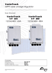
AUXILIARY CONTACTS 1 AND 2 EXTENDED FUNCTIONS
Generator control active
Number of starting attempts
Starter pulse duration (with AUX2)
Time before a starter pulse
Main contact hold/interrupt time
SYSTEM
Remote entry (Remote ON/OFF)
Remote entry active
Prohibits transfert relay
Prohibits inverter
Prohibits charger
Prohibits Smart-Boost
Prohibits grid feeding
Using a secondary value for the maximum current
of the AC source
Expert
1567
Second maximum current of the AC source (Input
limit)
16 Aac
Expert
1554
Decrease of the max. current of the source with
input voltage activated by command entry
No
Expert
Expert
Expert
Inst.
Inst.
Expert
Expert
Expert
Expert
Expert
Expert
1576
1578
1579
1600
1603
1296
1297
1565
1129
1130
1304
ON/OFF command
Activated by AUX1 state
Prohibits battery priority
Disable minigrid mode
Activate REG I, current control
Batteries priority as energy source
Battery priority voltage
Buzzer alarm duration
Auto restarts
After battery undervoltage
Number of batteries undervoltage allowed before
definitive stop
Expert
Expert
1404
1305
Time period for batteries undervoltages counting
Number of batteries critical undervoltage allowed
before definitive stop
Level
User manual
Parameter
Factory value
Delay 1 (AUX 2)
Contact activated with the SOC 2 of battery (AUX 2)
V 4.2.1
12 h
No
30%
0.2 h
No
20%
0h
90 % SOC
0.2 h
Yes
No
600 min
No
5
3 sec
3 sec
0 sec
Open
No
No
No
No
No
No
No
No
No
No
No
No
12.9/25.8/51.6 Vdc
0 min
Yes
3
0 sec
10
11
Studer Innotec SA
Quickguide RCC-02/-03
Expert
User
ref.
1405
Expert
Expert
Expert
Expert
Expert
Expert
Expert
Expert
Inst.
Inst.
Inst.
Expert
Expert
Expert
Expert
Expert
Expert
Expert
Expert
Inst.
Inst.
Inst.
Expert
Expert
Expert
Expert
Expert
Expert
Inst.
Inst.
Inst.
Inst.
Inst.
1131
1132
1533
1134
1111
1484
1485
1486
1550
1415
1399
1468
1282
1283
1461
1462
1555
1547
1571
1437
1577
1556
1522
1127
1523
1524
1525
1526
1610
1622
1623
1613
1624
Level
Parameter
Factory value
Time period for critical batteries undervoltages
counting
After battery overvoltage
After inverter or Smart-Boost overload
Delay to restart after an overload
After overtemperature
Autostart to the battery connection
System earthing (Earth - Neutral)
Prohibited ground relay
Continuous neutral
Parameters saved in flash memory
Global ON of the system
Global OFF of the system
Reset of all the inverters
MULTI XTENDER SYSTEM
Integral mode
Multi inverters allowed
Multi inverters independents. Need reset {1468}
Battery cycle synchronized by the master
Allow slaves standby in multi-Xtender system
Splitphase: L2 with 180 degrees phaseshift
Minigrid compatible
Minigrid with shared battery energy
is central inverter in distributed minigrid
GRID-FEEDING
Grid feeding allowed
Max grid feeding current
Battery voltage target for forced grid feeding
Forced grid feeding start time
Forced grid feeding stop time
Use of the defined phase shift curve for injection
Cos phi at P = 0%
Cos phi at the power defined by param {1613}
Power of the second cos phi point in % of Pnom
Cos phi at P = 100%
10 sec
Yes
Yes
5 sec
Yes
No
Yes
No
Yes
No
Yes
No
Yes
Yes
No
No
Yes
No
No
10 Aac
12/24/48 Vdc
20:00 hh:mm
20:00 hh:mm
No
1
1
60%
1
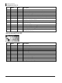
ADJUSTMENT OF THE BSP
Level
Basic
Basic
Basic
12
User
Parameter
ref.
6000 BASIC SETTINGS
6001
Nominal capacity
6002
Nominal discharge duration (C-rating)
V 4.2.1
Factory value
110 Ah
20 h
User manual
Studer Innotec SA
Quickguide RCC-02/-03
Level
Basic
Basic
Expert
Basic
Inst.
Expert
Expert
Expert
Expert
Expert
Expert
Expert
Expert
Expert
Expert
Expert
User
Parameter
ref.
6017
Nominal shunt current
6018
Nominal shunt voltage
6003
Reset of battery history
6004
Restore default settings
6005
Restore factory settings
6016 ADVANCED SETTINGS
6031
Reset of user counters
6019
Self-discharge rate
6020
Nominal temperature
6021
Temperature coefficient
6022
Charge efficiency factor
6023
Peukert's exponent
6042
Activate the end of charge synchronization
6024
End of charge voltage level
6025
End of charge current level
6026
Minimum duration before end of charge
Factory value
500 A
50 mV
3 %/month
20 °C
0.5 %cap/°C
80%
1.2
No
13.2/26.4/52.8 V
2 %cap
240 s
ADJUSTMENT OF THE VARIOTRACK MPPT
Level
Basic
Expert
Basic
Basic
Basic
Basic
Basic
Basic
Basic
Inst.
Expert
Basic
Expert
Expert
Expert
Basic
Expert
Expert
Expert
Basic
Expert
Expert
User
ref.
10000
10054
10001
10037
10005
10009
10017
10021
10056
10057
10003
10037
10002
10036
10004
10005
10006
10007
10008
10009
10010
10011
User manual
Parameter
Factory value
BASIC SETTINGS
Block manual programming (dip-switch)
Voltage of the system
Synchronisation battery cycle with Xtender
Floating voltage
Absorption voltage
Equalization allowed
Equalization voltage
Restore default settings
Restore factory settings
BATTERY MANAGEMENT AND CYCLE
Synchronisation battery cycle with Xtender
Battery charge current
Temperature compensation
Floating phase
Floating voltage
Force phase of floating
Absorption phase
Absorption phase allowed
Absorption voltage
Force absorption phase
Absorption duration
V 4.2.1
No
Automatic
Yes
13.6/27.2/54.4 Vdc
14.4/28.8/57.6 Vdc
No
15.6/31.2/62.4 Vdc
Yes
80 Adc
-3 mV/°C/cell
13.6/27.2/54.4 Vdc
Yes
14.4/28.8/57.6 Vdc
120 min
13
Studer Innotec SA
Quickguide RCC-02/-03
Expert
Expert
Expert
Basic
Expert
Basic
Expert
Expert
Expert
Expert
Expert
Expert
Expert
Expert
Expert
Expert
Expert
User
ref.
10012
10013
10016
10017
10018
10021
10020
10022
10052
10025
10026
10027
10019
10028
10029
10030
10031
Expert
Expert
10032
10033
Voltage level 2 to start a new cycle
Time period under voltage level 2 to start a new
cycle
Expert
Expert
Expert
Expert
Expert
Inst.
Inst.
Inst.
Basic
Inst.
Inst.
Expert
Expert
Expert
Expert
Expert
Expert
10034
10035
10038
10054
10060
10087
10043
10044
10056
10057
10058
10039
10040
10051
10088
10089
10090
Cycling restricted
Minimal delay between cycles
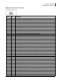
SYSTEM
Block manual programming (dip-switch)
Check Earthing
Disabling of the display button
Reset solar production counters
Reset daily min-max
Restore default settings
Restore factory settings
Parameters saved in flash memory
ON of the VarioTrack
OFF of the VarioTrack
Reset of all VarioTrack
AUXILIARY CONTACT 1
Operating mode (AUX 1)
Combination of the events for the auxiliary contact
(AUX 1)
Expert
Expert
Expert
10092
10093
10094
Contact activated in night mode (AUX 1)
Activated in night mode (AUX 1)
Delay of activation after entering night mode
(AUX 1)
Expert
10095
Activation time for the auxiliary relay in night
mode (AUX 1)
Expert
Expert
Expert
10096
10091
10097
Level
14
Parameter
Factory value
End of absorption triggered by the current
Current threshold to end absorption phase
Equalization phase
Equalization allowed
Force equalization
Equalization voltage
Equalization current
Equalization duration
Equalization with fixed interval
Days between equalizations
End of equalization triggered by the current
Current threshold to end equalization phase
Equalization before absorption phase
New cycle
Force a new cycle
Voltage level 1 to start a new cycle
Time period under voltage level 1 to start a new
cycle
Contact active on event (AUX 1)
VarioTrack is OFF (AUX 1)
Battery undervoltage (AUX 1)
V 4.2.1
No
10 Adc
No
15.6/31.2/62.4 Vdc
80 Adc
30 min
Yes
26 days
No
10 Adc
Yes
12.2/24.4/48.8 Vdc
30 min
11.8/23.6/47.2 Vdc
2 sec
Yes
1 hours
No
No control
No
Yes
Automatic
Any (Function OR)
No
1 min
1 min
No
No
User manual
Studer Innotec SA
Quickguide RCC-02/-03
Expert
Expert
Expert
Expert
Expert
Expert
Expert
Expert
Expert
Expert
Expert
Expert
Expert
Expert
Expert
Expert
Expert
Expert
Expert
Expert
Expert
Expert
Expert
Expert
User
ref.
10098
10099
10100
10102
10104
10105
10106
10107
10108
10109
10110
10111
10112
10113
10114
10115
10116
10117
10118
10119
10120
10121
10122
10123
Expert
10124
Expert
Expert
Expert
10125
10126
10127
Activation temperature of the contact (AUX 1)
Deactivation temperature of the contact (AUX 1)
Only activated if the battery is not in bulk phase
(AUX 1)
Expert
10128
Expert
10129
Contact active according to SOC (AUX 1) Only with
BSP
Contact activated with the SOC 1 of battery
(AUX 1)
Expert
Expert
Expert
10130
10131
10132
Contact activated below SOC 1 (AUX 1)
Delay 1 (AUX 1)
Contact activated with the SOC 2 of battery
(AUX 1)
50 % SOC
12 h
No
Expert
Expert
Expert
10133
10134
10135
Contact activated below SOC 2 (AUX 1)
Delay 2 (AUX 1)
Contact activated with the SOC 3 of battery
(AUX 1)
30%
0.2 h
No
Expert
Expert
Expert
Expert
Expert
10136
10137
10138
10139
10140
Contact activated below SOC 3 (AUX 1)
Delay 3 (AUX 1)
Contact deactivated over SOC (AUX 1)
Delay to deactivate (AUX 1)
Deactivate if battery in floating phase (AUX 1)
20%
0h
90 % SOC
0.2 h
No
Level
User manual
Parameter
Factory value
Battery overvoltage (AUX 1)
Earth fault (AUX 1)
PV error (48h without charge) (AUX 1)
Overtemperature (AUX 1)
Bulk charge phase (AUX 1)
Absorption phase (AUX 1)
Equalization phase (AUX 1)
Floating (AUX 1)
Reduced floating (AUX 1)
Periodic absorption (AUX 1)
Contact active according to battery voltage (AUX 1)
Battery voltage 1 activate (AUX 1)
Battery voltage 1 (AUX 1)
Delay 1 (AUX 1)
Battery voltage 2 activate (AUX 1)
Battery voltage 2 (AUX 1)
Delay 2 (AUX 1)
Battery voltage 3 activate (AUX 1)
Battery voltage 3 (AUX 1)
Delay 3 (AUX 1)
Battery voltage to deactivate (AUX 1)
Delay to deactivate (AUX 1)
Deactivate if battery in floating phase (AUX 1)
Contact active according to battery temperature
(AUX 1) With BSP or BTS
Contact activated with the temperature of
battery (AUX 1)
V 4.2.1
No
No
No
No
No
No
No
No
No
No
No
11.7/23.4/46.8 Vdc
1 min
No
11.9/23.9/47.8 Vdc
10 min
No
12.1/24.2/48.5 Vdc
60 min
13.5/27/54 Vdc
60 min
No
No
3 °C
5 °C
No
No
15
Studer Innotec SA
Quickguide RCC-02/-03
Expert
Expert
Expert
Expert
User
ref.
10141
10142
10143
10144
Expert
Expert
Expert
10146
10147
10148
Contact activated in night mode (AUX 2)
Activated in night mode (AUX 2)
Delay of activation after entering night mode
(AUX 2)
Expert
10149
Activation time for the auxiliary relay in night
mode (AUX 2)
Expert
Expert
Expert
Expert
Expert
Expert
Expert
Expert
Expert
Expert
Expert
Expert
Expert
Expert
Expert
Expert
Expert
Expert
Expert
Expert
Expert
Expert
Expert
Expert
Expert
Expert
Expert
10150
10145
10151
10152
10153
10154
10156
10158
10159
10160
10161
10162
10163
10164
10165
10166
10167
10168
10169
10170
10171
10172
10173
10174
10175
10176
10177
Expert
10178
Contact active on event (AUX 2)
VarioTrack is OFF (AUX 2)
Battery undervoltage (AUX 2)
Battery overvoltage (AUX 2)
Earth fault (AUX 2)
PV error (48h without charge) (AUX 2)
Overtemperature (AUX 2)
Bulk charge phase (AUX 2)
Absorption phase (AUX 2)
Equalization phase (AUX 2)
Floating (AUX 2)
Reduced floating (AUX 2)
Periodic absorption (AUX 2)
Contact active according to battery voltage (AUX 2)
Battery voltage 1 activate (AUX 2)
Battery voltage 1 (AUX 2)
Delay 1 (AUX 2)
Battery voltage 2 activate (AUX 2)
Battery voltage 2 (AUX 2)
Delay 2 (AUX 2)
Battery voltage 3 activate (AUX 2)
Battery voltage 3 (AUX 2)
Delay 3 (AUX 2)
Battery voltage to deactivate (AUX 2)
Delay to deactivate (AUX 2)
Deactivate if battery in floating phase (AUX 2)
Contact active according to battery temperature
(AUX 2) With BSP or BTS
Contact activated with the temperature of
battery (AUX 2)
Expert
Expert
Expert
10179
10180
10181
Contact activated over (AUX 2)
Contact deactivated below (AUX 2)
Only activated if the battery is not in bulk phase
(AUX 2)
Expert
10182
Contact active according to SOC (AUX 2) Only with
BSP
Level
16
Parameter
Factory value
Reset all settings (AUX 1)
AUXILIARY CONTACT 2
Operating mode (AUX 2)
Combination of the events for the auxiliary contact
(AUX 2)
-
V 4.2.1
Automatic
Any (Function OR)
No
1 min
1 min
No
No
No
No
No
No
No
No
No
No
No
No
No
11.7/23.4/46.8 Vdc
1 min
No
11.9/23.9/47.8 Vdc
10 min
No
12.1/24.2/48.5 Vdc
60 min
13.5/27/54 Vdc
60 min
No
No
3 °C
5 °C
No
User manual
Studer Innotec SA
Quickguide RCC-02/-03
Expert
User
ref.
10183
Expert
Expert
Expert
Level
Parameter
Factory value
Contact activated with the SOC 1 of battery
(AUX 2)
No
10184
10185
10186
Contact activated below SOC 1 (AUX 2)
Delay 1 (AUX 2)
Contact activated with the SOC 2 of battery
(AUX 2)
50 % SOC
12 h
No
Expert
Expert
Expert
10187
10188
10189
Contact activated below SOC 2 (AUX 2)
Delay 2 (AUX 2)
Contact activated with the SOC 3 of battery
(AUX 2)
30%
0.2 h
No
Expert
Expert
Expert
Expert
Expert
Expert
10190
10191
10192
10193
10194
10195
Contact activated below SOC 3 (AUX 2)
Delay 3 (AUX 2)
Contact deactivated over SOC (AUX 2)
Delay to deactivate (AUX 2)
Deactivate if battery in floating phase (AUX 2)
Reset all settings (AUX 2)
20%
0h
90 % SOC
0.2 h
No
-
ADJUSTMENT OF XCOM-MS
Level
Basic
Expert
Basic
Expert
Basic
Inst.
Basic
Basic
Basic
Basic
Basic
Basic
Basic
Basic
Basic
Basic
Basic
Basic
User
Parameter
ref.
8000 BASIC SETTINGS
8014
Address of the MPPT selected for the display
8001
Charge cycles synchronization activated
8002
Change the RS-485 identifier
8015
Restore default settings
8016
Restore factory settings
8003 BATTERY MANAGEMENT WITHOUT SYNCHRONIZATION
8004
Battery floating level
8005
Maximum delay in floating
8006
Battery voltage level to start a new cycle
8009
Battery absorption voltage
8010
Absorption time
8011
Battery temperature compensation
8017
Equalization allowed
8018
Equalization voltage
8019
Equalization time
8020
Equalization interval
8021
Equalization timeout
User manual
V 4.2.1
Factory value
1
No
0
13.6/27.2/54.5 Vdc
2 hours
12.5/25/49.9 Vdc
14.4/28.8/57.6 Vdc
2 hours
-5 mV/°C/cell
No
15.1/30.2/60.5 Vdc
1 hours
28 days
3 hours
17
Studer Innotec SA
Quickguide RCC-02/-03
USER INFORMATION XTENDER
Info.
no.
18
Name
Unit
3000
3005
3004
3006
Ubat
Ibat (m)
Ibat
Ubat ond
Vdc
Adc
Ausr
Vrip
3010
Phase
Text
3003
3028
3001
3002
3076
3078
Comp P
Mode
Tbat
Comp°C
E out YD
E out Day
Cdyn
Text
°C
Ctmp
kWh
kWh
3011
3012
3138
3137
3084
3080
3081
U in
I in
P in
P in a
F in
Eac in YD
Eac in Day
Vac
Aac
kVA
kW
Hz
kWh
kWh
3021
3022
3139
3136
3085
3082
3083
U out
I out
P out
Pout a
F out
Eac out YD
Eac out Dy
Vac
Aac
kVA
kW
Hz
kWh
kWh
3020
3030
3031
3032
3054
3055
3056
3019
3018
Transfert
Rel out
Aux 1
Aux 2
Aux I
Aux II
Lockings
Boost
P sharing
Text
Text
Text
Text
Text
Text
Text
Text
Description
Battery
Battery voltage
Battery charge current
Wanted battery charge current
Battery voltage ripple
Battery cycle phase (----, Bulk, Absorpt., Equalise, Floating,
R.float., Per.abs., Mixing, Forming)
Dynamic compensation of battery voltage
Operating state (----, Inverter, Charger, Boost, Injection)
Battery temperature
Temperature compensation of battery voltage
Discharge of battery of the previous day
Discharge of battery of the current day
Input AC
Input voltage
Input current
Input power
Input active power
Input frequency
Energy from of the previous day
Energy from of the current day
Output AC
Output voltage
Output current
Output power
Output active power
Output frequency
Consumers energy of the previous day
Consumers energy of the current day
General
State of transfer relay (Opened, Closed)
State of output relay (Opened, Closed)
State of auxiliary relay I (Opened, Closed)
State of auxiliary relay II (Opened, Closed)
Relay aux I mode (----, A, I, M, M, G)
Relay aux II mode (----, A, I, M, M, G)
Lockings flag
Boost active (Off, On)
Input limite reached (Off, On)
V 4.2.1
User manual
Studer Innotec SA
Quickguide RCC-02/-03
USER INFORMATION (BSP)
Info.
no.
7000
7001
7002
7003
7004
7006
7007
7008
7009
7010
7011
7012
7013
7017
7018
7019
7029
Name
Ubat
Ibat
SOC
Pbat
Trem
Crel
0d<
0d>
-1d<
-1d>
tot<
tot>
Ttot
cus>
cus<
Tcus
Tbat
Unit
Vdc
Adc
%
W
%
Ah
Ah
Ah
Ah
kAh
kAh
days
Ah
Ah
h
°C
Description
Battery voltage
Battery current
State of Charge
Power
Remaining autonomy
Relative capacity
Ah charged today
Ah discharged today
Ah charged yesterday
Ah discharged yesterday
Total kAh charged
Total kAh discharged
Total time
Custom charge Ah counter
Custom discharge Ah counter
Custom counter duration
Battery temperature
USER INFORMATION (VARIOTRACK)
Info.
no.
11000
11001
11002
11004
11005
11006
11007
11008
11010
11011
11015
Name
Unit
Ubat
Ibat
Upv
Psol
Tbat
Cd
Ed
kWhR
Cd-1
Ed-1
Type
Vdc
Adc
Vdc
kW
°C
Ah
kWh
kWh
Ah
kWh
Text
11016
Mode
Text
11017
PVmx
Vdc
User manual
Description
Battery voltage
Battery current
Voltage of the PV generator
Power of the PV generator
Battery temperature
Production in (Ah) for the current day
Production in (kWh) for the current day
Produced energy resettable counter
Production in (Ah) for the previous day
Production in (Wh) for the previous day
Model of VarioTrack (VT-80, VT-65)
Operating mode (Night, StartUp, ---, Charger, ---, Security, OFF, --, Charge , Charge V, Charge I, Charge T)
Max PV voltage for the current day
V 4.2.1
19
Studer Innotec SA
Quickguide RCC-02/-03
Info.
no.
11018
11019
11020
11021
11025
11026
Name
Unit
Ibmx
PVxP
Bmax
Bmin
Sd
Sd-1
Adc
kW
Vdc
Vdc
h
h
11034
Err
Text
11037
11038
EqIn
Phas
days
Text
11039
11040
11041
UbaM
IbaM
UpvM
Vdc
Adc
Vdc
11066
Sync
Text
Description
Max battery current of the current day
Max power production for the current day
Max battery voltage for the current day
Min battery voltage for the current day
Number of irradiation hours for the current day
Number of irradiation hours for the previous day
Type of error (No Error, BatoverV, Earth, No Batt, OverTemp,
BatOverV, PvOverV, Others, ---, ---, ---, ---)
Number of days before next equalization
Battery cycle phase (Bulk, Absorpt., Equalize, Floating, ---, ---,
R.float., Per.abs.)
Battery voltage (minute avg)
Battery current (minute avg)
PV voltage (minute avg)
Synchronisation state (---, ---, ---, ---, XTslave, VTslave, ---, ---,
VTmaster, Autonom.)
USER INFORMATION (XCOM-MS)
Info.
no.
9000
9001
9002
9004
9006
9007
9010
9011
9012
9013
9014
9017
20
Name
Uba1
Iba1
Uso1
Pou1
Ahd1
Whd1
Ibat
Pout
Ahj
Whj
nbr
Ubat
Unit
Vdc
Adc
Vdc
W
Ah
kWh
A
kW
Ah
kWh
Vdc
Description
Battery voltage of the selected MPPT
Battery current of the selected MPPT
Array voltage of the selected MPPT
Output power of the selected MPPT
Daily charge of the selected MPPT
Daily energy of the selected MPPT
Sum of battery currents
Sum of of the output powers
Sum of daily charges
Sum of daily energy
Number of MPPT
Average battery voltage
V 4.2.1
User manual
Studer Innotec SA
Quickguide RCC-02/-03
MESSAGES AND ACCOUNT OF EVENTS
Level
User
ref.
Basic
Basic
Basic
Basic
Basic
Basic
Basic
Basic
Basic
Installer
Basic
Basic
Basic
Basic
Basic
Basic
Basic
Installer
Basic
Basic
Basic
Basic
Basic
Basic
Basic
Basic
Basic
Basic
Basic
Basic
Basic
Basic
Basic
Basic
Basic
Basic
Basic
Basic
Basic
Basic
Basic
Basic
Basic
User manual
0
1
2
3
4
5
6
7
8
9
10
11
12
13
14
15
16
17
18
19
20
21
22
23
24
25
26
27
28
29
30
31
32
33
34
35
36
37
38
39
40
41
42
Description
Warning (000): Battery low
Warning (001): Battery too high
Warning (002): Bulk charge too long
Message (003): ACin synchronization in progress
Message (004): Input frequency ACin wrong
Message (005): Input frequency ACin wrong
Message (006): Input voltage ACin too high
Message (007): Input voltage ACin too low
Halted (008): Inverter overload SC
Halted (009): Charger short circuit
Message (010): System startup in progress
Message (011): ACin Energy quota
Message (012): Use of battery temperature sensor
Message (013): Use of additionnal remote control
Halted (014): Overtemperature EL
Halted (015): Inverter overload BL
Warning (016): Fan error detected
Message (017): Programing mode
Warning (018): Excessive battery voltage ripple
Halted (019): Battery undervoltage
Halted (020): Battery overvoltage
Message (021): Input limit reached, no transfert
Error (022): Voltage presence on AC-out
Error (023): Phase not defined
Message (024): Check the clock battery
Error (025): Unknow command board. Upgrade needed
Error (026): Unknow Power board. Upgrade needed
Error (027): Unknow extension board. Upgrade needed
Error (028): Voltage incompatibility Power - Command
Error (029): Voltage incompatibility Ext. - Command
Error (030): Power incompatibility Power - Command
Error (031): Command Board soft incompatibility
Error (032): Power board soft incompatibility
Error (033): Extension board soft incompatibility
Error (034): FID corruption Factory return
Message (035): Memory structure modified
Warning (036): Parameter file lack
Warning (037): Message file lack. Upgrade advised
Warning (038): Upgrade of the device software advised
Warning (039): Upgrade of the device software advised
Warning (040): Upgrade of the device software advised
Warning (041): Overtemperature TR
Halted (042): Unauthorized energy source at the output
V 4.2.1
21
Studer Innotec SA
Quickguide RCC-02/-03
Level
Basic
Basic
Basic
Basic
Basic
Basic
Basic
Basic
Basic
Basic
Basic
Basic
Basic
Basic
Basic
Basic
Basic
Basic
Basic
Basic
Basic
Basic
Basic
Basic
Basic
Basic
Basic
Basic
Basic
Basic
Basic
Basic
Basic
Basic
Basic
Basic
Basic
Basic
Basic
Basic
Basic
Basic
Basic
Basic
Basic
Basic
Basic
Basic
Basic
22
User
ref.
43
44
45
46
47
48
49
50
51
52
53
54
55
56
57
58
59
60
61
62
63
64
65
71
72
73
74
75
76
77
78
79
80
81
82
83
84
85
86
87
88
89
90
91
92
93
94
95
121
Description
Message (043): Start of monthly test
Message (044): End of successfully monthly test
Warning (045): Monthly autonomy test failed
Message (046): Start of weekly test
Message (047): End of successfully weekly test
Warning (048): Weekly autonomy test failed
Warning (049): Current over input limit, transfer opened
Error (050): Incomplete data transfer
Message (051): The update is finished
Message (052): Your installation is already updated
Error (053): Devices not compatible, update required
Message (054): Please wait. Data transfer in progress
Error (055): No SD card inserted
Warning (056): Upgrade of the RCC software advised
Message (057): Operation finished successfully
Error (058): Master synchro missing
Halted (059): Inverter overload HW
Warning (060): Time security 1512 AUX1
Warning (061): Time security 1513 AUX2
Warning (062): Genset, no ACin comming after AUX command
Message (063): Save parameter XT
Message (064): Save parameter BSP
Message (065): Save parameter MPPT
Error (071): Insufficient disk space on SD card
Error (072): CAN identification incorrect
Message (073): Datalogger is enabled on this RCC
Message (074): Save parameter BRIDGE MPPT
Message (075): MPPT MS address changed sucessfully
Message (076): Error during change of MPPT MS address
Message (077): Wrong Tristar DIP Switch position
Message (078): SMS or email sent
Error (079): More than 9 XTs in the system
Error (080): No battery (or reverse polarity)
Alarm (81): Earthing fault
Alarm (082): PV overvoltage
Message (083): No solar production in the last 48h
Message (084): Equalization performed
Error (085): Modem not availaible
Error (086): Incorrect PIN code, unable to initiate the modem
Error (087): Insufficent Signal from GPRS modem
Error (088): No connection to GPRS network
Error (089): No server access
Message (090): Server connected
Error (091): Update other RCC or Xcom-232i
Error (092): More than 3 RCC or Xcom-232i in the system
Error (093): More than 1 BSP in the system
Error (094): More than 1 Xcom MS in the system
Error (095): More than 15 VarioTrack in the system
Error (121): Impossible communication with target device
V 4.2.1
User manual
Studer Innotec SA
Quickguide RCC-02/-03
Level
User
ref.
Basic
Basic
Basic
Basic
Basic
Basic
Basic
Basic
Basic
Basic
Basic
Basic
Basic
Basic
Basic
Basic
Basic
Basic
Basic
User manual
122
123
124
125
126
127
128
129
130
131
132
133
134
137
138
139
140
145
146
Description
Error (122): SD card corrupted
Error (123): SD card not formatted
Error (124): SD card not compatible
Error (125): SD card format not recognized. Should be FAT
Error (126): SD card write protected
Error (127): SD card, file(s) corrupted
Error (128): SD card file or directory could not be found
Error (129): SD card has been prematurely removed
Error (130): Update directory is empty
Message (131): The VarioTrack is configured for 12V batteries
Message (132): The VarioTrack is configured for 24V batteries
Message (133): The VarioTrack is configured for 48V batteries
Message (134): Reception level of the GPRS signal
Message (137): VarioTrack master synchro lost
Message (138): XT master synchro lost
Message (139): Synchronized on VarioTrack master
Message (140): Synchronized on XT master
Error (145): SIM card blocked, PUK code required
Error (146): SIM card missing
V 4.2.1
23
Studer Innotec SA
Rue des Casernes 57
CH -1950 Sion, Switzerland
+41 (0) 27 205 60 80
+41 (0) 27 205 60 88
[email protected]
www.studer-innotec.com