1
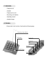
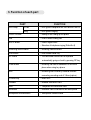
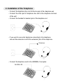
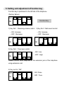
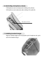
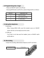
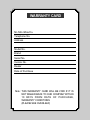
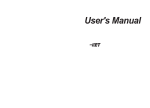
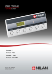
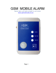
User's Manual
( DA - 207 )
CONTENTS
User’s Manual
1. Contents
2. Feature
3. Function of each part
4. Installation of the telephone
5. Sett ing and adjustment of function key
6. Controlling microphone volume
7. Installing headset hanger
8. Programming tone ringer
9. Using the telephone
10. Recording
11. Storage & Handling
1. Contents
-. Telephone set
-. Headset
-. Telephone line cord
-. Recording cord (Option)
-. Operating manual
-. Headset hanger
2. Feature
- Please refer to the function of each parts as following page
Re ce ivi ng Vol um e Swi tch
LE D La mp
He ad set # 2
He ad set # 1
Line
Extension
ON/OFF Bu tton
REC
3. Function of each part
PART
LED Lamp
FUNCTION
In use
- . LED lights in telephone call /LED blinks in MUTE
Ring
- . LED lights in ringing
ON/OFF button
- . Mak ing a call a hang up the phone
Dial
- . Pres s it when m aking call
M UTE button
- . Caller's signal mute
- . Selection of telephone ringing (Refer No.8)
Receiving volum e switch
- . Receiving volume control
LNR button
- . Last number redial k ey
RP button
- . The last dialed num ber can be repeated
Flash button
- . Receiving call c an be transferred to the other
REC
- . Recording can be done by external recorder
Function key
- . Refer No.5
Headset
- . Headset connection Jac k
Line
- . Telephone line connection Jack
Extension
- . Extension Jack to connect to the other phone
M icrophone volume switc h
-. Microphone volume control
automatically going on-hook by pressing RP key
phone when using key-phone
connecting rec ording cord of 3.5mm (option)
4. Installation of the Telephone
-. Connect the telephone line cord to the line jack of the telephone set
-. Connect the other part of telephone line cord to the telephone terminal
of the wall
-. Connect the headset to headset jack of the telephone set
-. If you want to use extra telephone connecting to the telephone,
connect the extension cord to the extension jack of the telephone.
Telephone
-. Connect the telephone cord to the MODEM of computer
MODEM
5. Setting and adjustment of function key
Function key is positioned to the left side of the telephone
(Factory Set-up)
OFF
Function Key
ON
1) Key No.1 : Receiving volume control
2) Key No.2 : Bell sound control
-. ON : Increase
-. ON : Increase
-. OFF : Decrease
-. OFF : Decrease
OFF
OFF
ON
ON
3) Key No.3 : Tone level control
OFF
ON
- ON : Low
- OFF : High
Please connect extra telephone to the extension jack of the telephone
using extension cord.
4) Key no.4 to “ON”
OFF
ON : Pulse
OFF : Tone
ON
6. Controlling microphone volume
1) Microphone volume increase when rotating to the left side
2) Microphone volume decrease when rotating to the right side
Mi cro ph on e Vo lu me
7. Installing headset hanger
Align the headset hanger with the projection part of telephone side, push
and fix the headset hanger.
8. Programming tone ringer
- Please set ON/OFF switch to be off hook
- Pressing MUTE button and # button, please change dial No. as follows ;
Dial NO.
Repetition rate
3
One time (slow)
6
Four times (normal)
9
10 times (fast)
9. Using the telephone
1) Receiving
- When ringing (RING LED), wear the headset, press on ON/OFF
switch and talk over the telephone with the caller.
2) Calling up
- If you want to call, take wear the headset, press on ON/OFF switch
and the dial no.
10. Recording
Connect the recording cable between telephone and PC as follows ;
PC Micr op ho ne J ack
3 .5 mm pl u g
11. Storage & Handling
1) Storage
Avoid the places that have direct sunlight , ill ventilat es, moistures,
trembles, dusts or electrical noise.
2) Notice
- Do not modify or decomposes this product by yourself
- Do not handle this product with wet hand.
- Clean the surface of this product with dry soft cloth.
- K eep the headset away from dust and dirt, whic h can cause
premature wear of parts.
- W ipe the headset with dampened clot h occasionally, or cleaning
solvents to clean the headset.
Warranty
We will repair or replace, at our opinion, this product if found defective
due to materials or workmanship within the warranty period beginning from
the original date of purchase. It is warranted by authorized representative for
the period specified.
The original dated purchase receipt must be presented to the authorized
service center when t he serv ice is rendered. On all carry-in models,
transportat ion to and from the service st ation is t he responsibility of the
purchaser.
This warrant y does not cover damages due t o accident, fire, flood,
earthquake and or ot her acts of god; misuse, incorrect line voltage,
improper installation or unauthorized repairs, commercial use of damages
occurred in shipping. Exterior and interior finish, lamp, glasses, plastic parts
and temperat ure probes are not covered under this warranty. Customer
adjustment according to the owner's manual are not covered under this
warranty. This warranty is automatically void if the serial no is missing or
altered.
WARRANTY CARD
Mr./Mrs./Miss/Co.
Telephone No.
Address
Model No.
Brand
Serial No.
Invoice No.
Dealer
Date of Purchase
Note : THIS WARRANTY CARD WILL BE VOID IF IT IS
NOT MAILED BACK TO OUR COMPANY WITHIN
10 DAYS FROM DATE OF PUR CH ASE,
WARRANTY CONDITIONS
(PLEASE SEE OVERLEAF)