1
Manual
for
NOVO 7-845GV
Page 1 of 1
ANOVO IPC User’s Manual
User’s Manual
www.anovotech.com
Manual
for
NOVO 7-845GV
Page 2 of 2
Contents
Copyright Notice ------------------------------------------------------ 4
Quick instruction ------------------------------------------------------------ 4
CHAPTER 1
INSTRUCTIONS
1.1 Instruction --------------------------------------------------- 5
--------------------------------------------- 5
1.2 Key Features
1.2.1 Size
------------------------------------------------- 5
1.2.2 Microprocessor ------------------------------------ 5
1.2.3 Chipset
-------------------------------------------- 5
1.2.4 System Memory -------------------------------------- 5
1.2.5 On-Board VGA ------------------------------------ 5
1.2.6 On-Board LAN --------------------------------------- 6
1.2.7 On-board IDE
-------------------------------------- 6
1.2.8 On-Board Peripherals --------------------------------- 6
1.2.9 Advance Function ---------------------------------- 6
1.2.10 Watchdog Timer ---------------------------------------- 6
1.2.11 BIOS
------------------------------------ 6
CHAPTER 2 INSTALLATION INTRODUCTIONS
2.1 External Connectors -------------------------------------2.1.1 Keyboard/Mouse Connector(MKB) --------2.1.2 VGA Connector --------------------------------------2.1.3 LAN Connector --------------------------------------2.1.4 Onboard USB Connector ----------------------2.1.5 External Keyboard/Mouse Connector ------2.1.6 AUX_Power
--------------------------------------2.1.7 ATX_PC Power connector ----------------------2.1.8 CPUFAN Connector -------------------------------2.1.9 UART1,2
----------------------------------------2.1.10 Power Connector ---------------------------------2.1.11 Parallel Port Connector ------------------------2.2 Jumper Setting
-----------------------------------------2.2.1 Clear CMOS ----------------------------------------2.2.2 FSB Frequency Setting:JFS1,JFS2 ---------2.2.3 Watchdog setting : JWD -----------------------
7
7
7
7
8
8
9
9
10
10
11
12
12
13
13
13
Manual
for
NOVO 7-845GV
Page 3 of 3
2.2.4 BIOS write protect: JAV ------------------------ 13
2.2.5 UART2 mode : JP2,JP3,JP4 ------------------- 13
2.2.6 Power Supply select: J_Power1 ------------- 13
CHAPTER 3、BIOS Setting
--------------------------------------
16
3.1 MAIN MENU
--------------------------------------- 17
3.2 Standard CMOS Features ------------------------ 18
3.3 Advanced BIOS Features ------------------------- 19
3.4 Advanced Chipset Features ------------------------------ 21
3.5 Integrated Peripherals
------------------------------- 23
3.6 Power Management Setup ------------------------------ 25
3.7 PnP/PCI Configurations ------------------------------ 27
3.8 PC Health Status
----------------------------------- 28
3.9 Frequency/Voltage Control --------------------------- 28
3.10 Load Optimized Defaults --------------------------- 29
3.11 Set Supervisor/ User Password
----------------- 29
Manual
for
NOVO 7-845GV
Page 4 of 4
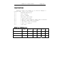
Item Checklist:
Completely check your package .If you discover damaged or
missing items, contact your retailer.
□√
ANOVO7845 Motherboard
□√
User’s manual
□√
Drivers’CD-ROM
□√
IDE ribbon cable:ATA66
□√
1 Floppy ribbon cable
□√
1 Audio port and 1 COM port ribbon cable with braket
□√
1 COM port ribbon cable with braket
□√
1 USB ribbion cable with braket
□√
1 PS/2 1 to 2 adapter
□√
3-Pin cable
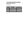
Ordering Information:
CPU
Memory
VGA
Audio
LAN
NOVO-7845GVEA
400/533FSB
DDR266/333
1
1
1
NOV0-7845GVE
400/533FSB
DDR266/333
1
NO
1
NOVO-7845GVA
400/533FSB
DDR266/333
1
1
NO
Rem
ark
Manual
for
NOVO 7-845GV
Page 5 of 5
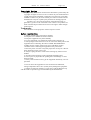
Copyright Notice
The proprietary information contains in this document is protected by the
copyright. All rights are reserved. It is not allow any non-authorization in
copied, photocopied, translated or reduced to any electronic or machine
readable in whole or in part form without prior written consent from the
manufacturer except for copied by the purchaser for backup purposes.
We take every care in the preparation of this document, but no
guarantee is given as to the correctness of its contents. Our products are
under continual improvement and we reserve the right to make changes
without notice.
Trademarks
All trademarks are the properties of their respective owners.
Safety Instruction
1. Always read the safety instructions carefully.
2. Keep this User’s Manual for future reference.
3. Keep this equipment away from humidity.
4. Lay this equipment on a reliable flat surface before setting it up.
5. The openings on the enclosure are for air convection hence protects the
equipment from overheating. DO NOT COVER THE OPENINGS.
6. Make sure the voltage of the power source and adjust properly
110/220V before connecting the equipment to the power inlet.
7. Place the power cord such a way that people can not step on it. Do not
place anything over the power cord.
8. Always Unplug the Power Cord before inserting any add-on card or
module.
9. All cautions and warnings on the equipment should be noted.
10. Never pour any liquid into the opening that could damage or cause
electrical shock.
11. If any of the situations arises, get the equipment checked by a service
personnel:
12. Do not leave this equipment in an environment unconditioned,
storage temperature above 600 C (1400F),It may damage the equipment.
13. Danger of explosion if battery is incorrectly replaced. Replace only
with the same or equivalent type recommended by the manufacturer.
Manual
for
NOVO 7-845GV
Page 6 of 6
NOVO-7845GV Quickly Instruction
Jumper Setting:
Please make sure all jumper was normal setting before you connect power to
NOVO-7845GV,The normal setting as below::
Jumper
Normal Value:
Normal Setting
JP2
COM2:RS232
Pin3~5, Pin4~6 short
JP3
COM2:RS232
Pin3~5, Pin4~6 short
JP4
COM2:RS232
Pin 1~2 short
CLR_CMOS
Clear Jumper Setting
Pin 2~3 short
JWD
Watch Dog Burst Mode
Pin 1~2 short
J_Power Power Supply Mode(Normal:ATX) Pin 2~3 short
Manual
for
NOVO 7-845GV
Page 7 of 7
Chapter 1 . Instruction
1.1 Novo 7845GV Instruction
Thank you for purchasing the Novo 7845GV CPU cards for
ANOVO Technology Co.,Ltd.
The Novo7845GV support 400/533Mhz FSB.. The NOVO7-845GV
CPU cards utilize Intel 845GV chipset consisting of two components: the
Intel 845GV Memory Controller Hub and the 82801DB Controller speed
of 200/266/333 MHz, providing a fully compatible ,high performance and
cost-effective industry control platform. The new integrated technologies,
together integrated onboard 64M VGA controller ,integrated LAN, 4
USB ports, and ATA 100/66/33 ,give customers an advanced solution at
an reasonable price . It provides 400/533MHz host bus speed to support
Intel Pentium 4 socket 478 processors. It also provides advanced features
such as ACPI and BIOS-Protect.
1.2
Key Feature
1.2.1 Size
*
Full-size PICMG: 338.5mm x 122mm
1.2.2 CPU
*
Supports Socket 478 for Intel® Pentium 4/Celeron processors
*
Core Frequency from 1.4 GHz to 2.8 GHz and up* (*not tested yet)
*
Support 400/533 MHz Host Bus speed
1.2.3 Chipset
Intel® 845GV Chipset: 82845GV( GMCH )and 82801DB( ICH4 )
1.2.4 System memory)
*
Support two 184-pin DDR200/266/333MHz Memory
*
Up to 2.0 GB of 333MHz DDR SDRAM
1.2.5 Onboard VGA
*
Integrate 64M VGA controller.
1.2.6 Onboard LAN
*
ICH4 integration LAN controller
*
Intel 82562ET (option)
*
Provides one 10/100M LAN interface.
1.2.7 On-board IDE
Manual
for
NOVO 7-845GV
*
*
*
Page 8 of 8
An IDE controller integrated in ICH4
Support PIO and DMA communication modes
Two fast EIDE interfaces supporting up to four IDE devices including
IDE hard disks and CDROM drive.
1.2.8 On-board I/O
*
Winbond W83627HF-AW super I/O chip.。
*
One Floppy Driver connecter port,Support two FDD with 360K, 720K,
1.2M, 1.44M or 2.88MB.
* Two high speed 16550 UART port,COM1:RS-232,COM2:RS-232/422/485
can select.
*
One parallel port
1.2.9 Advanced features
*
Provides audio output with a AC’97 connector
*
PCI2.2 Specification compliant
*
Provides on-board PS/2 mouse and keyboard ports
*
Four USB ports supported. USB2.0 Specification compliant.
*
Supports Windows 98/2000/XP software soft-off
*
Supports two fan off when the system enters suspend mode.
*
On-board super I/O chip supports system monitoring (monitors
CPU and system temperature, voltages and fan speed.
1.2.10 Watchdog Timer
*
Can be enabled or disabled by software and jumper.
*
Write I/o port OEFH with to disable watchdog.
*
Time-out timing select from 1 to 239 seconds or from 1 to 239
minutes.
*
Watchdog function can be set to Reset/NMI/Disable.
1.2.11 BIOS
*
Supports flash ROM with 2Mbit memory size, plug and play ready.
*
Supports CD-ROM/USB devices/LS-120 ZIP boot UP.
Chapter 2
Installation Instructions
2.1 External Connectors
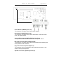
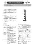
2.1.1 Keyboard/Mouse Connector( MKB )
Manual
for
NOVO 7-845GV
Page 9 of 9
This connector is for the usage of PS/2 mouse and keyboard through a
One-two Adapter. If using a standard AT keyboard, an adapter should
be used to suit this connector.
PS2
KB/MS Connector
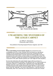
2.1.2 VGA Connector
The monitor output connector is for output to VGA-compatible device.
VGA Connector
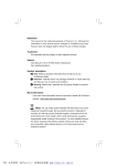
2.1.3 LAN Connector
RJ45 Connector
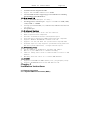
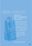
2.1.4 USB Connectors( USB1,2,3,4 )
You should use a 10-pin cable to connect onboard USB headers and
USB devices.
Manual
for
NOVO 7-845GV
Page 10 of 10
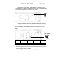
2.1.5 External Keyboard Connector( KB )
External Mouse Connector(MS)
2.1.6 Aux_Power
Be sure to connect the Aux_Power supply plug to the connector in
proper orientation.
Manual
for
NOVO 7-845GV
Page 11 of 11
2.1.7 ATX_PC 电源接口
The CPU-card provide a 3pin ATX_PC power connector, please
connector the 5VSB/PS_ON and GND line to industry motherboard by
3pin cable when you use ATX power supply mode.
2.1.8 CPUFAN
The fan speeds of CPUFAN can be detected and viewed in “PC
Health” section of the BIOS.
Manual
for
NOVO 7-845GV
Page 12 of 12
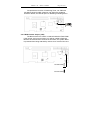
2.1.9 UART1,2
The serial ports UART1,2 connectors can be connected with
serial port devices. You can enable/disable them and choose the
IRQ or I/O address in “INTEGRATED PERIPHERALS” from BIOS
SETUP.
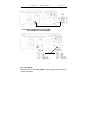
2.1.10
Front Panel Connector
Manual
for
NOVO 7-845GV
Page 13 of 13
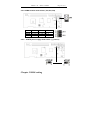
Power Button (PWRBT)(Pin13,14)
The connector connects to the case’s power buttton.
Reset Button ((RSTBT)(Pin17,18 )
The connector connects to the case’s reset switch. Press the switch
once, the system resets.
Power LED Connector (PWR LED)(Pin1,Pin3,Pin5)
The power LED indicates the status of the main power switch.
IDE_LED Connector (IDE_LED)(Pin19,20)
The connector connects to the case’s IDE indicator LED indicating the
activity status of IDE hard disk。
Key-Lock Connector (KEY LK)(Pin7,9)
The connector can be connected to the keyboard lock switch on the
case for locking the keyboard.
Speaker Connector (Speaker)(Pin2,4,6,8)
Manual
for
NOVO 7-845GV
Page 14 of 14
The connector connects to the case’s buzzer.
2.1.11 LPT Connector
The board provide a LPT connector, you can connect it to pro
2.2 Jumper setting.
Jumpers are located on the CPU card, they represent, clear
CMOS jumper JCC etc. Pin 1 for all jumpers are located on the side
with a thick white line (Pin1
),refer to the CPU card’s
,to
silkscreen . Jumpers with three pins will be shown as
represent pin1 & pin2 connected and
to represent pin2 &
pin3 connected.
。
2.2.1 Clear CMOS(CLR_CMOS1)
Manual
for
NOVO 7-845GV
Page 15 of 15
If you want to clear CMOS, unplug the AC power supply first,
close JCC (pin1 & pin2) once, set JCC back to the normal status with
pin2 & pin3 connected, then power on the system.。
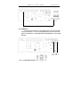
2.2.2 FSB Frequency setting( JFS1,JFS2 )
Jumpers labeled JFS is located on the motherboard providing
users with CPU on the correct clock. The host bus speed can be set
as 100/133MHz or AUTO select. Refer to the chart below for the
location of these jumpers, and the table for information on how to set
them.
FSB
JFS2
JFS1
100
1~2(H)
2~3(L)
133
1~2(H)
OPEN(H)
200
2~3(L)
OPEN(H)
AUTO
1~2(H)
1~2
Note:
Overclocking your processor is not recommended. We do not guarantee
the overclocking system to be stable.
2.2.3 Watchdog Timer Action Jumper setting ( JWD )
Manual
for
NOVO 7-845GV
Page 16 of 16
We provide the function of Watchdog Timer, set JWD with
pin1&pin2 closed for NMI; otherwise, set JWD with pin2&pin3
closed for Reset, set JWD all open for disabling watchdog action.
2.2.4 BIOS-Protect Jumper (JAV)
The BIOS of the CPU card is contained inside the Flash ROM.
If the jumper JAV is set as closed, you will be unable to flash the
BIOS to the motherboard. However in this status, the system BIOS
is protected from being attacked by serious virus such as CIH virus.
Manual
for
NOVO 7-845GV
Page 17 of 17
2.2.5 COM2 transfer mode select.( JP2,JP3,JP4)
RS232
RS422
RS485
2.2.6
JP2
3~5,4~6
1~3,2~4
1~3,2~4
JP3
3~5,4~6
1~3,2~4
1~3,2~4
JP4
1~2
3~4
5~6,7~8
AT/ATX power supply mode select .(J_Power1)
Chapter 3 BIOS setting
Manual
for
NOVO 7-845GV
Page 18 of 18
Instruction
This chapter provides information on the BIOS Setup program and
allows you to configure the system for optimum use.
You may need to run the Setup program when:
■ An error message appears on the screen during the system booting up,
and requests you to run SETUP.
■ You want to change the default settings for customized features.
Entering BIOS Setup
Power on the computer and the system will start post (Power On Self
Test) process. When the “DEL: Setup” message below appears on the
screen, press <DEL> key to enter BIOS setup.
Instruction Control Key
<↑>
Move to the previous item
Move to the next item
<↓>
Move to the item on the left-hand side
<←>
<→>
Move to the item on the right-hand side
<Enter> Select the item
Jump to the Exit menu or returns to the main menu from
<Esc>
a submenu
<+/PU> Increase the numeric value or make changes
<F7>
Decrease the numeric value or make changes
General help, only for Status Page Setup Menu and Option
Page Setup Menu
Load the default CMOS value from Fail-Safe default table ,
only for Option Page Setup Menu.
Load Optimized defaults
<F10>
Save all the CMOS changes and exit
<-/PU>
<F1>
<F6>
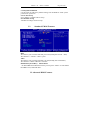
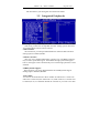
3.1 MAIN MENU
Manual
for
NOVO 7-845GV
Page 19 of 19
The screen will appear the Main Menu after you enter
Phoenix-AwardBIOS CMOS Setup Utility .The Main Menu displays
twelve configurable functions and two exit function choices . Use arrow
keys to move among the items and press <Enter> to enter the submenu
Standard CMOS Features
Use this menu for basic system configurations, such as time, date etc.
Advanced BIOS Features
Use this menu to setup the items of BIOS enhanced features.
Advanced Chipset Features
Use this menu to change the values in the chipset registers and optimize your
system’s performance
Integrated Peripherals
Use this menu to specify your settings for integrated peripherals..
Power Management Features
Use this menu to specify your settings for power management.
PNP/PCI Configurations
This entry appears if your system supports PnP/PCI.
PC Health Status
This entry shows your PC health status.
Frequency/Voltage Control
Use this menu to specify your settings for frequency/voltage control.
Set Supervisor Password
Use this menu to set Supervisor Password.
Set User Password
Use this menu to set User Password.
Manual
for
NOVO 7-845GV
Page 20 of 20
Load Optimized Defaults
Use this menu to load factory default settings into the BIOS for stable system
performance operations.
Save & Exit Setup
Save changes to CMOS and exit setup.
Exit Without Saving
Abandon all changes and exit setup.
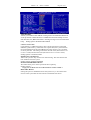
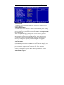
3.2
Standard CMOS Features
Date
This allows you to set the date that you want (usually the current date).
The format is < month > <date><year>
Time
This allows you to set the time that you want(usually the current date).
The format is <Hour><Minute><second>.
IDE Primary/Secondary Master/Slave
On IDE HDD Auto-Detection menu you can press <Enter> to auto-detect
the HDD’s size, head and other .
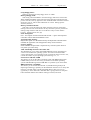
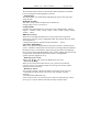
3.3 Advanced BIOS Features
Manual
for
NOVO 7-845GV
Page 21 of 21
Virus Warning
Allows you to choose the VIRUS warning feature for IDE Hard Disk boot
sector protection. If this function is enabled and someone attempt to write
data into this area, BIOS will show a warning message on screen and alarm
beep. Setting option :Disabled and Enabled.
CPU L1 & L2 Cache
Cache memory is additional memory that is much faster than conventional
DRAM (system memory). When the CPU requests data, the system transfers
the requested data from the main DRAM into cache memory, for even faster
access by the CPU. The setting controls the internal cache (also known as L1
or level 1 cache) and external cache (also known as L2 or level 2 cache).
Setting options: Disabled,Enable
Quick Power On Self Test
Allows the system to skip certain tests while booting. This will decrease the
time needed to boot the system.
Setting options: Enabled /Disabled
First/Second/Third Boot Device
The items allow you to select your boot device priority.
Setting options :
Floppy/LS120/HDD-0/SCSI/CDROM/HDD-1/HDD-2/HDD-3
Boot Other Device:
Setting the option to “Enabled” allows the system to try to boot from other
devices if the system fails to boot from the 1st/2nd/3rd boot device.
Manual
for
NOVO 7-845GV
Page 22 of 22
Swap Floppy Drive:
Setting to Enabled will swap floppy drives A: and B:.
Boot Up Floppy Seek:
This setting causes the BIOS to search for floppy disk drives at boot time.
When enabled, the BIOS will activate the floppy disk drives during the boot
process: the drive activity light will come on and the head will move back and
forth once. First A: will be done and then B: if it exists. Setting options:
Disabled, Enabled.
Boot Up NumLock Status:
This item is to set the Num Lock status when the system is powered on.
Setting to On will turn on the Num Lock key when the system is powered on.
Setting to Off will allow end users to use the arrow keys on the numeric
keypad. Setting options: On, Off.
Gate A20 Option:
Fast – lets chipset control GateA20 and Normal – a pin in the keyboard
controller controls GateA20.Default is Fast.
Typematic Rate Setting:
Keystrokes repeat at a rate determined by the keyboard controller-when
enabled, the typematic rate and typematic delay can be selected.
Security Option:
Select whether the password is required every time the system boots or
only when you enter setup .
APIC Mode/Mps Version Control For OS:
This field allows you to select which MPS (Multi-Processor Specification)
version to be used for the operating system. You need to select the MPS
version supported by your operating system. To find out which version to use,
consult the vendor of your operating system. Settings: 1.4, 1.1.
OS Select For DRAM> 64MB
This allows you to run the OS/2® operating system with DRAM larger than
64MB. When you choose Non-OS2, you cannot run the OS/2® operating
system with DRAM larger than 64MB. But it is possible if you choose OS2.
HDD S.M.A.R.T. Capablility:
This allows you to activate the S.M.A.R.T. (Self-Monitoring Analysis &
Reporting Technology) capability for the hard disks. S.M.A.R.T is a utility that
monitors your disk status to predict hard disk failure. This gives you an
opportunity to move data from a hard disk that is going to fail to a safe place
before the hard disk becomes offline. Settings: Enabled, Disabled.
Manual
for
NOVO 7-845GV
Page 23 of 23
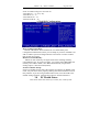
3.4 Advanced Chipset Features
DRAM Timing Selectable:
Selects whether DRAM timing is controlled by the SPD (Serial
Presence Detect) EEPROM on the DRAM module. Setting to By SPD
enables the following fields automatically to be determined by BIOS
based on the configurations on the SPD. Selecting Manual allows users to
configure these fields manually.
CAS Latency Time
This controls the timing delay (in clock cycles) before SDRAM
starts a read command after receiving it. Settings: 2, 2.5 (clocks). 2
(clocks) increases the system performance the most while 2.5 (clocks)
provides the most stable performance.
Active to Precharge Delay:
This setting controls the precharge delay, which determines the
timing delay for DRAM precharge. Settings: 5 clocks, 6 clocks, 7 clocks.
DRAM RAS# to CAS# Delay:
When DRAM is refreshed, both rows and columns are addressed
separately. This setup item allows you to determine the timing of the
Manual
for
NOVO 7-845GV
Page 24 of 24
transition from RAS (row address strobe) to CAS (column address
strobe). The less the clock cycles, the faster the DRAM performance.
Setting options: 3 clocks, 2 clocks.
DRAM RAS# Precharge
This item controls the number of cycles for Row Address Strobe
(RAS) to be allowed to precharge. If insufficient time is allowed for the
RAS to accumulate its charge before DRAM refresh, refresh may be
incomplete and DRAM may fail to retain data. This item applies only
when synchronous DRAM is installed in the system. Available settings: 2
clocks, 3 clocks.
Memory Frequency For :
This setup item allows you to determine the Frequency of the
Memory . Option Select:Auto/PC100/PC133.
System BIOS Cacheable:
Selecting Enabled allows caching of the system BIOS ROM at
F0000h- FFFFFh, resulting in better system performance. However, if
any program writes to this memory area, a system error may result.
Setting options: Enabled, Disabled
Video
BIOS Cacheable:
This item allows you select the Video BIOS Cache statue. Setting
options: Enabled, Disabled
Delayed Transaction:
When set to Enabled ,this feature frees the PCI bus when the
CUP is accessing 8-bit ISA cards. This process normally consumes
about 50-60 PCI clocks without PCI delayed transaction .Set this field
to Disabled when using ISA cards that are not PCI 2.1
compliant .Configuration Option: Enabled/ Disabled.
AGP Aperture Size<MB>:
This setting controls just how much system RAM can be allocated
to AGP for video purposes. The aperture is a portion of the PCI memory
address range dedicated to graphics memory address space. Host cycles
that hit the aperture range are forwarded to the AGP without any
translation. The option allows the selection of an aperture size of 4MB,
8MB, 16MB, 32MB, 64MB, 128MB, and 256 MB.
On-Chip VGA Setting:
Manual
for
NOVO 7-845GV
Page 25 of 25
The item allows you setting the on-board VGA statues.
3.5
Integrated Peripherals
On-Chip Primary/Secondary PCI IDE
This setting controls the on-chip IDE controller. Setting options: Disabled,
Auto/Mode0/Mode1/Mode 2/Mode 3/Mode 4
USB Controller:
The item allows you setting Enable/Disable the onboard USB Controllers.
Setting Option: Enabled ,Disable.
USB 2.0 Controller:
This entry is for disable/enable EHCI controller only. The BIOS itself may/
may not have speed USB support. If the BIOS has high speed USB support
built in, the support will be automatically turn on when high speed device were
attached.
USB Keyboard Support:
The item allows you setting Enable/Disable the USB Keyboard Support .
Setting Option: Enabled ,Disable.
AC97 Audio
Auto allows the motherboard to detect whether an audio device is used. If an
audio device is detected, the onboard AC’97 (Audio Codec’97) controller will
be enabled; if not, it is disabled. Disable the controller if you want to use other
Manual
for
NOVO 7-845GV
Page 26 of 26
controller cards to connect an audio device. Settings: Auto, Disabled.
AC97 Modem
Auto allows the motherboard to detect whether a modem is used. If a modem is
detected, the onboard AC’97 modem controller will be enabled; if not, it is
disabled. Disable the controller if you want to use other controller cards to
connect a modem. Settings: Auto, Disabled.
Onboard/CNR LAN selection
The field determines whether the onboard LAN controller is activated. Setting
options: Enabled, Disabled.
Init Display First
This item can define the first Display device. Option selected:
Onboard/AGP Or PCI Slot
IDE HDD Block Mode
If your IDE hard drive supports block mode select Enabled for automatic
detection of the optimal number of block read/writes per sector the drive
can support.
Onboard FDC Controller
The item allows you setting Enable/Disable the onboard FDC Controllers.
Setting Option: Enabled , Disable
3.6 Power Management Setup
Manual
for
NOVO 7-845GV
Page 27 of 27
ACPI Function
This setting is used to enable/disable the ACPI Function. Setting options:
Enabled, Disabled.
Power Management
This field allows you to activate or deactivate the automatic power saving
features . The [User Defined] option allows you to set the period of
inactivity before the system enters suspend mode. Refer to Suspend Mode
later in this section .
When set to [Max Saving], system power is conserved to its greatest
amount. This setting automatically puts the system into suspend mode after
a brief period of system inactivity. [Min Saving’ allows the least power
saving as the system enters suspend mode onle after a long period of
inactivity. Configuration option :[User Defined][Min Saving][Max
Saving]。
Video Off Method
The item defines the video off features. The Display Power Management
System[DPMS] feature allows the BIOS to control the video display card
if it supports the DPMS feature.[Bland Screen] only blanks the screen. Use
this for monitors without power management or “green” features.
[V/H SYNC +Bland] blanks the screen and turns off vertical and horizontal
scanning. Configuration options: [Blank Screen] [V/H SYNC +Bland]
[DPMS]
Video Off In Suspend
Manual
for
NOVO 7-845GV
Page 28 of 28
This item determines when to activate the video off feature for monitor
power management. Setting Option: YES/NO
Suspend Type
This item allows you selected the Suspend Type by [PwrOn Suspend] /
[Stop Grand]
MODEM Use IRQ
The item is used to select the IRQ line for Modem use.
Setting Option:NA/3/4/5/7/9/10/11
Suspend Mode
Sets the time period before the system goes into suspend mode . Setting
Option: Disable、1Min、2Min、4 Min、8Min、12Min、20Min、30 Min、
40 Min、1Hour.
HDD Power Down
Shuts down any IDE hard disk drives in the system after a period of
inactivity as set in thi suser-configurable field. This feature does not affect
SCSI hard drives.
Configuration options: Disabled/1min/2min/3min/…/15min.
Soft-Off by PWR-BTTN
When set to [instant-off],the ATX switch can be used as a normal system
power –off button when pressed for less than 4 seconds.[Delay 4sec]allows
the button to have a dual functio where pressing less than 4 seconds puts
the system in sleep mode.Regardless of the setting ,holding the ATX switch
for more than 4 seconds powers off the system.. Configuration
options:[Instant-off][Delay 4sec]
Wake-Up by PCI card
When set to Enable, the system can Wake up by PCI card.
Power On by Ring
When set to Enabled, the feature allows your system to be awakened
from the power saving modes through an incoming call from the modem.
Settings: Enabled, Disabled.
Resume by Alarm
This is used to enable or disable the feature of booting up the system on
a scheduled time/date from the soft off (S5) state. Settings: Enabled,
Disabled.
Alarm Date/Hour/Minute/Second
If Resume By Alarm is set to Enabled, the system will automatically resume
(boot up) on a specific date/hour/minute/second specified in these
Manual
for
NOVO 7-845GV
Page 29 of 29
fields. Available settings for each item are:
Alarm Date 01 ~ 31, Every Day
Alarm Hour 00 ~ 23
Alarm Minute 00 ~ 59
Alarm Second 00 ~ 59
3.7 PnP/PCI Configurations
Reset Configuration Data
Default is Disabled . Select Enabled to reset Extended System
Configuration Data ESCD) when you exit Setup if you have installed a nes
add-on and the system reconfiguraton has caused such a serious conflict
that the OS cannot boot.
Resources Controlled By:
BIOS can auto matically configure all the boot and Plug and Play
compatible devices. If you choose Auto, you cannot select IRQ DMA and
memory base address fields, since BIOS automatically assigns them.
Setting Option : Manual/AUTO(ESCD)
PCI/VGA Palette Snoop:
Some non-standard VGA cards, like graphics accelerators or MPEG video
cards, may not show colors properly. Setting this field to Enabled corrects
this problem. If you are using standard VGA cards, leave this field to the
default setting Disabled. Configuration options: Disabled/Enabled
3.8
PC Health Status
This section shows the status of your CPU, fan, overall system
Manual
for
NOVO 7-845GV
Page 30 of 30
status, etc. Monitor function is available only if there is hardware
monitoring mechanism Onboard。
3.9 Frequency/Voltage Control
Auto Detect PCI CLK
This item allows you Enable/Disable AUTO-Detect PCI Clk.
Spread Spectrum:
When the motherboard clock generator pulses, the extreme values (spikes)
of the pulses creates EMI (Electromagnetic Interference). The Spread
Manual
for
NOVO 7-845GV
Page 31 of 31
Spectrum function reduces the EMI generated by modulating the pulses so that
the spikes of the pulses are reduced to flatter curves. If you do not have any
EMI problem。
leave the setting at Disabled for optimal system stability and performance.
But if you are plagued by EMI, select Enabled for EMI reduction. Remember
to disable Spread Spectrum if you are overclocking because even a slight
jitter can introduce a temporary boost in clockspeed which may just cause
your overclocked processor to lock up. Available settings: Enabled, Disabled.
CPU Host/PCI Clock:
This item allows you to select the CPU Front Side Bus clock frequency.
The field also allows you to overclock the processor by adjusting the FSB
clock to a higher frequency.
3.10 Load
Optimized Defaults
This option allows you to load the default values for each of the parameters
on the Setup menus.When you select this option,a confirmation window
appears. Select{Yes} to load default values,Select Exit Saving Change or
make other changes before saving the values to the non –volatile RAM.
3.12 Set Supervisor/ User Password
When you select this function, a message as below will appear on the screen:
Type the password, up to six characters in length, and press <Enter>. The
password typed now will replace any previously set password from CMOS
memory. You will be prompted to confirm the password. Retype the password
and press <Enter>. You may also press <Esc> to abort the selection and
not enter a password.
To clear a set password, just press <Enter> when you are prompted to enter the
password. A message will show up confirming the password will be disabled.
Once the password is disabled, the system will boot and you can enter Setup
without entering any password.
When a password has been set, you will be prompted to enter it every time
you try to enter Setup. This prevents an unauthorized person from changing
any part of your system configuration.
Manual
for
NOVO 7-845GV
Page 32 of 32
Additionally, when a password is enabled, you can also have AMIBIOS to
request a password each time the system is booted. This would prevent
unauthorized
use of your computer. The setting to determine when the password
prompt is required is the PASSWORD CHECK option of the ADVANCED
BIOS FEATURES menu. If the PASSWORD CHECK option is set to Always,
the password is required both at boot and at entry to Setup. If set to Setup,
password prompt only occurs when you try to enter Setup.
Notes:
Supervisor password: Can enter and change the settings of the setup menu.
User password: Can only enter but do not have the right to change the
settings of the setup menu.