1
SAFETY PRECAUTIONS
(Read these precautions before using this product.)
Before using this product, please read this manual and the relevant manuals carefully and pay full attention
to safety to handle the product correctly.
In this manual, the safety precautions are classified into two levels: "
WARNING" and "
CAUTION".
WARNING
Indicates that incorrect handling may cause hazardous conditions,
resulting in death or severe injury.
CAUTION
Indicates that incorrect handling may cause hazardous conditions,
resulting in minor or moderate injury or property damage.
Under some circumstances, failure to observe the precautions given under "
CAUTION" may lead to
serious consequences.
Observe the precautions of both levels because they are important for personal and system safety.
Make sure that the end users read this manual and then keep the manual in a safe place for future
reference.
[Design Precautions]
WARNING
When a safety programmable controller detects an error in an external power supply or a failure in
programmable controller, it turns off all the outputs.
Create an external circuit to securely stop the power of hazard by turning off the outputs. Incorrect
configuration may result in an accident.
Create short current protection for a safety relay, and a protection circuit such as a fuse, and
breaker, outside a safety programmable controller.
When data/program change, or status control is performed from a personal computer to a running
safety programmable controller, create an interlock circuit outside the sequence program and safety
programmable controller to ensure that the whole system always operates safely.
For the operations to a safety programmable controller, pay full attention to safety by reading the
relevant manuals carefully, and establishing the operating procedure.
Furthermore, for the online operations performed from a personal computer to a safety CPU module,
the corrective actions against a communication error due to a cable connection fault, etc. should be
predetermined as a system.
A-1
[Design Precautions]
WARNING
All output signals from a safety CPU module to the CC-Link Safety system master module are
prohibited to use.
These signals can be found in the CC-Link Safety System Master Module User's Manual.
Do not turn ON or OFF these signals by sequence program, since turning ON/OFF these output
signals of the programmable controller system may cause malfunctions and safety operation cannot
be guaranteed.
All output signals from a safety CPU module to the CC-Link IE Field Safety Network master/local
module (with safety functions) are prohibited to use.
These signals can be found in the MELSEC-QS CC-Link IE Field Safety Network Master/Local
User's Manual.
Do not turn ON or OFF these signals by sequence program, since turning ON/OFF these output
signals of the programmable controller system may cause malfunctions and safety operation cannot
be guaranteed.
When a safety remote I/O module has detected a CC-Link Safety error, it turns off all the outputs.
Note that the outputs in a sequence program are not automatically turned off.
If a CC-Link Safety or CC-Link IE Field Network error has been detected, create a sequence
program that turns off the outputs in the program.
If the CC-Link Safety or CC-Link IE Field Network is restored with the outputs on, it may suddenly
operate and result in an accident.
To inhibit restart without manual operation after safety functions was performed and outputs were
turned OFF, create an interlock program which uses a reset button for restart.
To prevent an illegal operation and malfunction, do not connect a safety programmable controller to
the Internet or to a wireless LAN.
[Design Precautions]
CAUTION
Do not install the wires of external devices or communication cables together with the main circuit
lines or power cables. Keep a distance of 100mm (3.94 inch) or more between them.
Failure to do so may result in malfunction due to noise.
After the CPU module is powered on or is reset, the time taken to enter the RUN status varies
depending on the system configuration, parameter settings, and/or program size.
Design circuits so that the entire system will always operate safely, regardless of the time.
A-2
[Installation Precautions]
CAUTION
Use the safety programmable controller in an environment that meets the general specifications in
this manual. Failure to do so may result in electric shock, fire, malfunction, or damage to or
deterioration of the product.
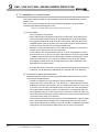
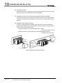
To mount the module, while pressing the module mounting lever located in the lower part of the
module, fully insert the module fixing projection(s) into the hole(s) in the base unit and press the
module until it snaps into place.
Incorrect interconnection may cause malfunction, failure, or drop of the module.
Secure the module to the base unit with screws.
Tighten the screws within the specified torque range.
Undertightening can cause drop of the screw, short circuit, or malfunction.
Overtightening can damage the screw and/or module, resulting in drop, short circuit, or malfunction.
Shut off the external power supply (all phases) used in the system before mounting or removing the
module.
Failure to do so may result in damage to the product.
Do not directly touch any conductive part of the module.
Doing so can cause malfunction or failure of the module.
[Wiring Precautions]
WARNING
Shut off the external power supply (all phases) used in the system before wiring.
Failure to do so may result in electric shock or damage to the product.
After wiring, attach the included terminal cover to the module before turning it on for operation.
Failure to do so may result in electric shock.
A-3
[Wiring Precautions]
CAUTION
Individually ground the FG and LG terminals of the programmable controller with a ground
resistance of 100 or less.
Failure to do so may result in electric shock or malfunction.
Use a solderless terminal with insulation sleeve for wiring of a terminal block.
Use up to two solderless terminals for a single terminal.
Use applicable solderless terminals and tighten them within the specified torque range.
If any spade solderless terminal is used, it may be disconnected when a terminal block screw comes
loose, resulting in failure.
Check the rated voltage and terminal layout before wiring to the module, and connect the cables
correctly.
Connecting a power supply with a different voltage rating or incorrect wiring may cause a fire or
failure.
Tighten the terminal block mounting screws, terminal screws, and module fixing screws within the
specified torque range.
Undertightening of the terminal block mounting screws or terminal screws can cause short circuit,
fire, or malfunction.
Overtightening can damage the screw and/or module, resulting in drop, short circuit, or malfunction.
Undertightening of the module fixing screws can cause drop of the module.
Overtightening can damage the screw and/or module, resulting in drop.
Prevent foreign matter such as dust or wire chips from entering the module.
Such foreign matter can cause a fire, failure, or malfunction.
A protective film is attached to the top of the module to prevent foreign matter, such as wire chips,
from entering the module during wiring.
Do not remove the film during wiring.
Remove it for heat dissipation before system operation.
A-4
[Wiring Precautions]
CAUTION
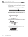
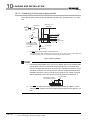
Mitsubishi programmable controllers must be installed in control panels.
Connect the main power supply to the power supply module in the control panel through a relay
terminal block.
Wiring and replacement of a power supply module must be performed by qualified maintenance
personnel with knowledge of protection against electric shock.
(For the wiring methods, refer to Section 10.3.)
[Startup and Maintenance Precautions]
WARNING
Do not touch any terminal while power is on.
Doing so will cause electric shock.
Correctly connect the battery connector.
Do not charge, disassemble, heat, short-circuit, or solder the battery, or throw it into the fire.
Doing so will cause the battery to produce heat, explode, or ignite, resulting in injury and fire.
Shut off the external power supply (all phases) used in the system before cleaning the module or
retightening the terminal block mounting screws, terminal screws, or module fixing screws.
Failure to do so may result in electric shock.
Tighten these screws within the specified torque range.
Undertightening of the terminal block mounting screws or terminal screws can cause short circuit,
fire, or malfunction.
Overtightening can damage the screw and/or module, resulting in drop, short circuit, or malfunction.
Undertightening of the module fixing screws can cause drop of the module.
Overtightening can damage the screw and/or module, resulting in drop.
A-5
[Startup and Maintenance Precautions]
CAUTION
The online operations performed from a personal computer to a running safety programmable
controller (Program change when a safety CPU module is RUN, device test, and operating status
change such as RUN-STOP switching) have to be executed after the manual has been carefully
read and the safety has been ensured.
Following the operating procedure predetermined at designing, the operation has to be performed by
an instructed person.
When changing a program while a safety CPU module is RUN (Write during RUN), it may cause a
program breakdown in some operating conditions.
Fully understand the precautions described in the GX Developer's manual before use.
Do not disassemble or modify the modules.
Doing so may cause failure, malfunction, injury, or a fire.
If the product is repaired or remodeled by other than the specified FA centers or us, the warranty is
not covered.
Use any radio communication device such as a cellular phone or PHS (Personal Handy-phone
System) more than 25cm (9.85 inches) away in all directions from the programmable controller.
Failure to do so may cause malfunction.
Shut off the external power supply (all phases) used in the system before wiring.
Failure to do so may cause the module to fail or malfunction.
After the first use of the product, do not mount/remove the module to/from the base unit, and the
terminal block to/from the module more than 50 times (IEC 61131-2 compliant) respectively.
Exceeding the limit may cause malfunction.
Do not drop or apply shock to the battery to be installed in the module.
Doing so may damage the battery, causing the battery fluid to leak inside the battery.
If the battery is dropped or any shock is applied to it, dispose of it without using.
Before handling the module, touch a conducting object such as a grounded metal to discharge the
static electricity from the human body.
Failure to do so may cause the module to fail or malfunction.
A-6
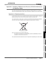
[Disposal Precautions]
CAUTION
When disposing of this product, treat it as industrial waste.
When disposing of batteries, separate them from other wastes according to the local regulations.
(For details of battery regulations in EU member states, refer to Appendix 4.)
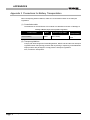
[Transportation Precautions]
CAUTION
When transporting lithium batteries, follow the transportation regulations.
(For details of the regulated models, refer to Appendix 3.)
A-7
CONDITIONS OF USE FOR THE PRODUCT
(1) Although MELCO has obtained the certification for Product's compliance to the international safety
standards IEC61508, EN954-1/ISO13849-1 from TUV Rheinland, this fact does not guarantee that
Product will be free from any malfunction or failure. The user of this Product shall comply with any
and all applicable safety standard, regulation or law and take appropriate safety measures for the
system in which the Product is installed or used and shall take the second or third safety measures
other than the Product. MELCO is not liable for damages that could have been prevented by
compliance with any applicable safety standard, regulation or law.
(2) MELCO prohibits the use of Products with or in any application involving, and MELCO shall not be
liable for a default, a liability for defect warranty, a quality assurance, negligence or other tort and a
product liability in these applications.
(a) power plants,
(b) trains, railway systems, airplanes, airline operations, other transportation systems,
(c) hospitals, medical care, dialysis and life support facilities or equipment,
(d) amusement equipments,
(e) incineration and fuel devices,
(f) handling of nuclear or hazardous materials or chemicals,
(g) mining and drilling,
(h) and other applications where the level of risk to human life, health or property are elevated.
A-8
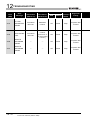
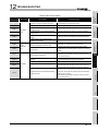
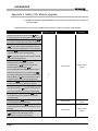
REVISIONS
The manual number is given on the bottom left of the back cover.
Print Date
Manual Number
Revision
Sep., 2006
SH(NA)-080626ENG-A First edition
May, 2007
SH(NA)-080626ENG-B
Correction
Section 2.2, 4.1, 5.1, 6.1, 9.1.1, 9.1.3, 10.1, 10.3.1, 10.3.2, 12.2.1, 12.2.10
Addition
Section 12.2.12
Apr., 2008
SH(NA)-080626ENG-C
Correction
ABOUT MANUALS, GENERIC TERMS AND ABBREVIATIONS, Section 1.1,
2.1, 4.2, 4.3, 4.4, 5.1, 5.3, 6.2, 8.1, 9.1.3, 9.1.4, 9.2.1, 10.2.1, 10.2.3, 10.3.1,
10.3.2, 11.1, 11.2, 12.2.1, 12.2.3, 12.2.4, 12.2.5, 12.2.7, 12.2.8, 12.2.9, 12.2.12,
12.3.1, 12.3.3, 12.3.4, 12.3.5, 12.3.6, 12.3.7, 12.3.8, 12.6, 12.7
Addition
Section 2.1.1, Appendix 2
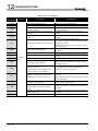
Sep., 2008
SH(NA)-080626ENG-D
Correction
Section 10.2.1
Addition
SAFETY PRECAUTIONS, Section 7.1, Appendix 4
Apr., 2009
SH(NA)-080626ENG-E
Change of a term
"PLC" was changed to "programmable controller".
Correction
ABOUT MANUALS GENERIC TERMS AND ABBREVIATIONS Chapter 1,
Section 2.1.1, Chapter 3, Chapter 9, Section 11.3.1, Section 11.3.2,
Section 12.3.3, Section 12.3.6
Feb., 2010
SH(NA)-080626ENG-F
Correction
SAFETY PRECAUTIONS, Section 2.1, 4.1, 7.1.1, 7.1.2, Chapter 11, Section
11.3.1, 12.3.3, Appendix 1.1, Appendix 1.3
Addition
CONDITIONS OF USE FOR THE PRODUCT
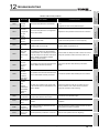
Jul., 2010
SH(NA)-080626ENG-G
Correction
SAFETY PRECAUTIONS, Section 1.1, 2.1, 2.1.1, 4.1, Chapter 9
Addition
Section 9.3
May, 2011
SH(NA)-080626ENG-H
Correction
SAFETY PRECAUTIONS, ABOUT MANUALS, GENERIC TERMS AND
ABBREVIATIONS Section 1.1, 2.1, 2.1.1, 8.1, 9.1.3, 9.2.2, Chapter 10, Section
12.2.7, 12.3.1, 12.3.4, 12.3.5, 12.6, 12.7, Appendix 2
May, 2012
SH(NA)-080626ENG-I
Correction
SAFETY PRECAUTIONS, Section 2.3, Chapter 3, Section 5.2, 5.3, 9.1.1, 9.2.1,
10.3.1, 12.6, Appendix 2
A-9
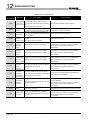
The manual number is given on the bottom left of the back cover.
Print Date
Manual Number
Revision
Jun., 2013
SH(NA)-080626ENG-J
Correction
Section 2.1.1, 5.3, 9.1.5
Deletion
Section 9.2.5
Japanese Manual Version SH-080607-J
This manual confers no industrial property rights or any rights of any other kind, nor does it confer any patent licenses.
Mitsubishi Electric Corporation cannot be held responsible for any problems involving industrial property rights which may
occur as a result of using the contents noted in this manual.
C
A - 10
2006 MITSUBISHI ELECTRIC CORPORATION
INTRODUCTION
Thank you for choosing the Mitsubishi MELSEC-QS Series of Safety Programmable Controllers.
Before using the equipment, please read this manual carefully to develop full familiarity with the functions
and performance of the QS series programmable controller you have purchased, so as to ensure correct
use.
CONTENTS
SAFETY PRECAUTIONS .................................................................................................................................A - 1
CONDITIONS OF USE FOR THE PRODUCT..................................................................................................A - 8
REVISIONS.......................................................................................................................................................A - 9
INTRODUCTION.............................................................................................................................................A - 11
CONTENTS ....................................................................................................................................................A - 11
ABOUT MANUALS ......................................................................................................................................... A - 19
HOW THIS MANUAL IS ORGANIZED ...........................................................................................................A - 21
HOW TO USE THIS MANUAL........................................................................................................................A - 22
GENERIC TERMS AND ABBREVIATIONS....................................................................................................A - 23
PRECAUTIONS FOR USE ............................................................................................................................. A - 24
CHAPTER1 OVERVIEW
1.1
Features........................................................................................................................................... 1 - 3
CHAPTER2 SYSTEM CONFIGURATION
2.1
1 - 1 to 1 - 7
2 - 1 to 2 - 7
System Configuration ...................................................................................................................... 2 - 1
2.1.1
Precautions for system configuration ....................................................................................... 2 - 4
2.2
Configuration of Peripheral Devices ................................................................................................ 2 - 5
2.3
Checking Serial Number and Function Version............................................................................... 2 - 6
CHAPTER3 GENERAL SPECIFICATIONS
3 - 1 to 3 - 2
CHAPTER4 CPU MODULE
4 - 1 to 4 - 7
4.1
Performance Specifications ............................................................................................................. 4 - 1
4.2
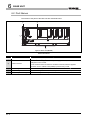
Part Names...................................................................................................................................... 4 - 3
4.3
Switch Operation after Writing a Program ....................................................................................... 4 - 5
4.4
Reset Operation............................................................................................................................... 4 - 6
A - 11
CHAPTER5 POWER SUPPLY MODULE
5 - 1 to 5 - 5
5.1
Specifications................................................................................................................................... 5 - 1
5.2
Precaution when connecting the uninterruptible power supply........................................................ 5 - 3
5.3
Names of Parts and Settings ........................................................................................................... 5 - 4
CHAPTER6 BASE UNIT
6 - 1 to 6 - 2
6.1
Specification .................................................................................................................................... 6 - 1
6.2
Part Names ...................................................................................................................................... 6 - 2
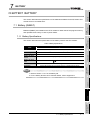
CHAPTER7 BATTERY
7.1
Battery (Q6BAT) .............................................................................................................................. 7 - 1
7.1.1
7.1.2
Battery Specifications ............................................................................................................... 7 - 1
Installation of Battery ................................................................................................................ 7 - 2
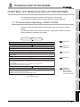
CHAPTER8 CPU MODULE START-UP PROCEDURES
8.1
Standards relevant to the EMC Directive.................................................................................. 9 - 2
Installation in a control panel .................................................................................................... 9 - 3
Cables....................................................................................................................................... 9 - 4
Power Supply Module............................................................................................................... 9 - 7
Others ....................................................................................................................................... 9 - 7
Requirement to Conform to the Low Voltage Directive.................................................................... 9 - 9
9.2.1
9.2.2
9.2.3
9.2.4
9.2.5
9.3
9 - 1 to 9 - 13
Requirements for Conformance to EMC Directive........................................................................... 9 - 1
9.1.1
9.1.2
9.1.3
9.1.4
9.1.5
9.2
8 - 1 to 8 - 3
Procedure before Operating in SAFETY MODE.............................................................................. 8 - 1
CHAPTER9 EMC, LOW VOLTAGE, AND MACHINERY DIRECTIVES
9.1
7 - 1 to 7 - 2
Standard applied for MELSEC-QS series programmable controller......................................... 9 - 9
MELSEC-QS series programmable controller selection........................................................... 9 - 9
Power supply .......................................................................................................................... 9 - 10
Control panel .......................................................................................................................... 9 - 10
External wiring ........................................................................................................................ 9 - 12
Requirements for compliance with the Machinery Directive .......................................................... 9 - 13
CHAPTER10 LOADING AND INSTALLATION
10 - 1 to 10 - 22
10.1
Calculating Heat Generation of programmable controller.............................................................. 10 - 3
10.2
Module Installation ......................................................................................................................... 10 - 5
10.2.1
10.2.2
10.2.3
10.3
Wiring........................................................................................................................................... 10 - 18
10.3.1
10.3.2
A - 12
Installation precautions ........................................................................................................... 10 - 5
Instructions for mounting the base unit................................................................................. 10 - 12
Installation and removal of module ....................................................................................... 10 - 15
Wiring precautions ................................................................................................................ 10 - 18
Connecting to the power supply module............................................................................... 10 - 22
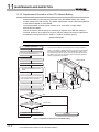
CHAPTER11 MAINTENANCE AND INSPECTION
11 - 1 to 11 - 11
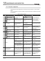
11.1
Daily Inspection ............................................................................................................................. 11 - 3
11.2
Periodic Inspection ........................................................................................................................ 11 - 4
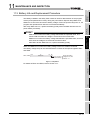
11.3
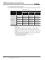
Battery Life and Replacement Procedure...................................................................................... 11 - 5
11.3.1
11.3.2
Battery lives of CPU modules................................................................................................. 11 - 6
Replacement Procedure of the CPU Module Battery ............................................................. 11 - 8
11.4
When programmable controller Has been Stored without a Battery............................................ 11 - 10
11.5
When Battery Has Gone Flat during Storage of a programmable controller ............................... 11 - 11
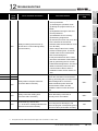
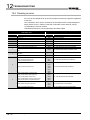
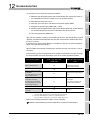
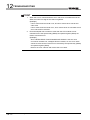
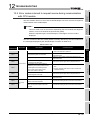
CHAPTER12 TROUBLESHOOTING
12 - 1 to 12 - 101
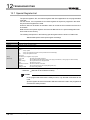
12.1
Troubleshooting Basics ................................................................................................................. 12 - 1
12.2
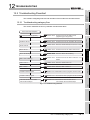
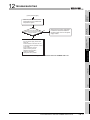
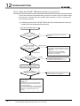
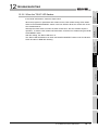
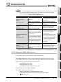
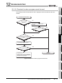
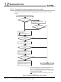
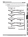
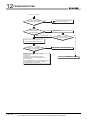
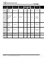
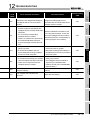
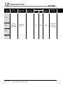
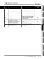
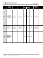
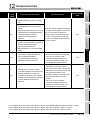
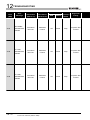
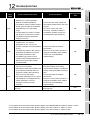
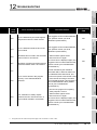
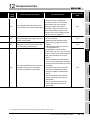
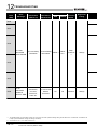
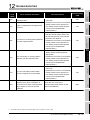
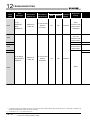
Troubleshooting Flowchart ............................................................................................................ 12 - 2
12.2.1
12.2.2
12.2.3
12.2.4
12.2.5
12.2.6
12.2.7
12.2.8
12.2.9
12.2.10
12.2.11
12.2.12
12.3
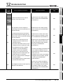
Troubleshooting category flow................................................................................................ 12 - 2
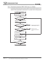
Flowchart for when the ERR terminal (negative logic) is off (opened) ................................... 12 - 3
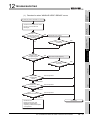
Flowchart for when the "POWER" LED turns off .................................................................... 12 - 5
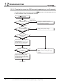
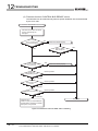
When the "ALIVE" LED does not turn on or turns off ............................................................. 12 - 7
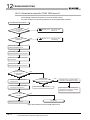
Flowchart for when the "RUN" LED turns off .......................................................................... 12 - 9
When the "RUN" LED flashes .............................................................................................. 12 - 10
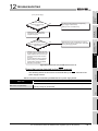
Flowchart for when the "ERR." LED turns on or flashes ...................................................... 12 - 11
When the "USER" LED turns on........................................................................................... 12 - 14
When the "BAT." LED turns on............................................................................................. 12 - 15
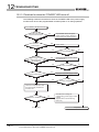
Flowchart for when a program cannot be read ..................................................................... 12 - 16
Flowchart for when a program cannot be written ................................................................. 12 - 17
Flowchart for when the CPU cannot communicate with the GX Developer ......................... 12 - 18
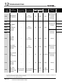
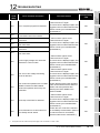
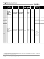
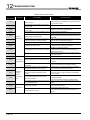
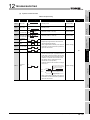
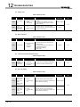
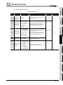
Error Code List............................................................................................................................. 12 - 20
12.3.1
12.3.2
12.3.3
12.3.4
12.3.5
12.3.6
12.3.7
12.3.8
Error codes ........................................................................................................................... 12 - 21
Reading an error code.......................................................................................................... 12 - 22
Error code list (1000 to 1999) ............................................................................................... 12 - 23
Error code list (2000 to 2999) ............................................................................................... 12 - 29
Error code list (3000 to 3999) ............................................................................................... 12 - 35
Error code list (4000 to 4999) ............................................................................................... 12 - 45
Error code list (5000 to 5999) ............................................................................................... 12 - 49
Error code list (8000 to 9000) ............................................................................................... 12 - 51
12.4
Clearing an error.......................................................................................................................... 12 - 65
12.5
Error codes returned to request source during communication with CPU module ...................... 12 - 68
12.6
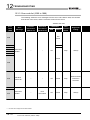
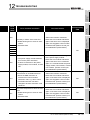
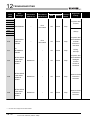
Special Relay List ........................................................................................................................ 12 - 77
12.7
Special Register List .................................................................................................................... 12 - 83
APPENDICES
Appendix 1
App- 1 to App - 9
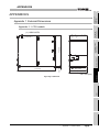
External Dimensions..........................................................................................................App- 1
Appendix 1.1
CPU module ..............................................................................................................App- 1
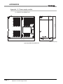
Appendix 1.2
Power supply module ................................................................................................App- 2
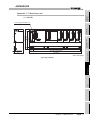
Appendix 1.3
Main base unit ...........................................................................................................App- 3
Appendix 2 Safety CPU Module Upgrade ............................................................................................App- 4
Appendix 3
Precautions for Battery Transportation..............................................................................App- 6
A - 13
Appendix 4
Handling of Batteries and Devices with Built-in Batteries in EU Member States...............App- 7
Appendix 4.1
Appendix 4.2
INDEX
A - 14
Disposal precautions .................................................................................................App- 7
Exportation precautions.............................................................................................App- 8
Index- 1 to Index- 2
(Related manual).................QSCPU User's Manual (Function Explanation, Program Fundamentals)
CONTENTS
CHAPTER1 OVERVIEW
1.1
Features
1.2
Program Storage and Operation
1.3
Devices and Instructions Convenient for Programming
1.4
How to Check the Serial No. and Function Version
CHAPTER2 PERFORMANCE SPECIFICATION
CHAPTER3 SEQUENCE PROGRAM EXECUTION
3.1
Sequence Program
3.1.1
3.1.2
Sequence program description method
Sequsence program operation
3.2
Concept of Scan Time
3.3
Operation Processing
3.3.1
3.3.2
3.3.3
Initial processing
I/O refresh
END processing
3.4
RUN, STOP Operation Processing
3.5
Operation Processing during Momentary Power Failure
3.6
Data Clear Processing
3.7
Numeric Values which can be Used in Sequence Programs
3.7.1
3.7.2
3.7.3
BIN (Binary Code)
HEX (Hexadecimal)
BCD (Binary Coded Decimal)
CHAPTER4 I/O NUMBER ASSIGNMENT
4.1
Definition of I/O Number
4.2
Concept of I/O Number Assignment
4.2.1
4.2.2
4.3
I/O Assignment by GX Developer
4.3.1
4.3.2
4.3.3
4.4
I/O numbers of base unit
I/O numbers of remote station
Purpose of I/O assignment by GX Developer
Concept of I/O assignment using GX Developer
Examples of I/O Number Assignment
Checking the I/O Numbers
CHAPTER5 MEMORIES AND FILES HANDLED BY CPU MODULE
5.1
Memories by CPU Module
A - 15
5.1.1
5.1.2
5.1.3
5.1.4
Memory configuration and storable data
Program memory
Standard ROM
Standard ROM program execution (boot run) and writing
5.2
Program File Structure
5.3
File Operation by GX Developer and Handling Precautions
5.3.1
5.3.2
5.3.3
5.3.4
File operation
Precautions for handling files
Memory capacities of files
File size units
CHAPTER6 FUNCTIONS
6.1
Function List
6.2
Safety CPU Operation Mode
6.2.1
6.2.2
6.2.3
6.2.4
6.2.5
Safety CPU operation mode
Checking safety CPU operation mode
Safety CPU operation mode switching
Operation of each function in each safety CPU operation mode and CPU operation status
Online operations that can be executed on the CPU module from GX Developer
6.3
CPU access password
6.4
PLC memory initialization
6.5
Setting to prevent continuous RUN in TEST MODE
6.6
Checking the ROM write count
6.7
Self-diagnostics Function
6.7.1
6.7.2
LED display for error
Cancel the error
6.8
Recording the operation contents and self-diagnostics error occurrence contents (operation/error history function)
6.9
Constant scan
6.10
Setting of Output (Y) Status when Changing between STOP and RUN
6.11
Clock Function
6.12
Remote Operation
6.12.1
6.12.2
6.12.3
6.13
Remote RUN/STOP
Remote RESET
Relationship of remote operation and CPU's RUN/STOP status
Monitor Function
6.14 Writing in Program during CPU Module RUN
6.14.1
Online change in ladder mode
6.15 Watchdog Timer(WDT)
6.16 Remote password
6.17 CPU Module System Display by GX Developer
6.18 LED Display
6.18.1
A - 16
Method to turn off the LED
CHAPTER7 COMMUNICATION WITH INTELLIGENT FUNCTION MODULE
7.1
Communication with CC-Link Safety master module
7.2
Communication with CC-Link IE Field Network Master/Local Module (With Safety Functions)
7.3
Communication with CC-Link IE Controller Network Module or MELSECNET/H Module
7.4
Communication with Ethernet Module
7.5
Communication using intelligent function module dedicated instructions
CHAPTER8 PARAMETERS
8.1
PLC Parameters
8.2
Network Parameters
8.3
Remote Password
CHAPTER9 DEVICE EXPLANATION
9.1
Device List
9.2
Internal User Devices
9.2.1
9.2.2
9.2.3
9.2.4
9.2.5
9.2.6
9.2.7
9.2.8
9.2.9
9.2.10
9.2.11
9.2.12
9.3
Input (X)
Output (Y)
Internal relay (M)
Annunciator (F)
Edge relay (V)
Link relay (B)
Link special relay (SB)
Timer (T)
Counter (C)
Data register (D)
Link register (W)
Link special register (SW)
Internal System Devices
9.3.1
9.3.2
Special relay (SM)
Special register (SD)
9.4
Nesting (N)
9.5
Constants
9.5.1
9.5.2
Decimal constant (K)
Hexadecimal constant (H)
CHAPTER10 CPU MODULE PROCESSING TIME
10.1
Scan Time
10.1.1
10.1.2
10.1.3
10.2
Structure and calculation of scan time
Time required for each processing included in scan time
Factors that increase the scan time
Other Processing Times
CHAPTER11 PROCEDURE FOR WRITING PROGRAM TO CPU MODULE
A - 17
11.1
Items to be examined for program creation
11.2
Procedure for writing program
11.3
Boot run procedure
APPENDICES
Appendix 1 Special Relay List
Appendix 2 Special Register List
Appendix 3 List of Parameter No
Appendix 4 Restrictions on Using CC-Link IE Controller Network Module with Safety CPU Module
Appendix 5 Restrictions on Using MELSECNET/H Module with Safety CPU Module
Appendix 6 Restrictions on Using Ethernet Module with Safety CPU Module
Appendix 7 Dedicated Instructions which can be used in Safety CPU Module
Appendix7.1
Appendix7.2
List of dedicated instructions
Programming using dedicated instructions
Appendix 8 Safety CPU Module Upgrade
Appendix 9 Access Range for Safety CPU Module
INDEX
A - 18
ABOUT MANUALS
Introduction Manual
Read the following manual before designing and constructing a safety system.
Manual No.
Manual Name
(Model Code)
Safety Application Guide
Explains the overview, construction method, laying and wiring examples, and application programs of the
SH-080613ENG
(13JR90)
safety-related system.
(Sold separately)
Related Manuals
The manual related to this product is shown below.
Please place an order as needed.
Manual No.
Manual Name
(Model Code)
QSCPU User's Manual (Function Explanation, Program Fundamentals)
Explains the functions, programming methods, devices and others that are necessary to create programs with the
SH-080627ENG
(13JR93)
QSCPU.
(Sold separately)
QSCPU Programming Manual (Common Instructions)
Explains how to use the sequence instructions, basic instructions, application instructions, and QSCPU dedicated
SH-080628ENG
(13JW01)
instructions.
(Sold separately)
CC-Link Safety System Master Module User's Manual
Explains the specifications, procedures and settings before operation, parameter settings, and troubleshooting of
SH-080600ENG
(13JR88)
the QS0J61BT12 CC-Link Safety system master module.
(Sold separately)
CC-Link Safety System Remote I/O Module User's Manual
Explains the specifications, procedures and settings before operation, parameter settings, and troubleshooting of
SH-080612ENG
(13JR89)
the CC-Link Safety system remote I/O modules.
(Sold separately)
MELSEC-QS CC-Link IE Field Network Master/Local Module User's Manual
Explains the specifications, procedures and settings before operation, parameter settings, and troubleshooting of
SH-080969ENG
(13JZ53)
a CC-Link IE Field Network master/local module (with safety functions).
(Sold separately)
CC-Link IE Controller Network Reference Manual
Explains the system configuration, performance specifications, functions, handling, wiring, and troubleshooting of
SH-080668ENG
(13JV16)
CC-Link IE Controller Network.
(Sold separately)
Q Corresponding MELSECNET/H Network System Reference Manual (PLC to PLC network)
Explains the specifications, procedures and settings before operation, parameter settings, programming, and
SH-080049
(13JF92)
troubleshooting of a MELSECNET/H network system for PLC to PLC network.
(Sold separately)
Q Corresponding Ethernet Interface Module User's Manual (Basic)
Explains the specifications, procedures for data communication with external devices, line connection (open/
close), fixed buffer communication, random access buffer communication, and troubleshooting of the Ethernet
module.
SH-080009
(13JL88)
(Sold separately)
A - 19
Manual No.
Manual Name
(Model Code)
Q Corresponding Ethernet Interface Module User's Manual (Application)
Explains the e-mail function, programmable controller CPU status monitoring function, communication function via
CC-Link IE Controller Network, MELSECNET/H or MELSECNET/10, communication function using the data link
instructions, file transfer function (FTP server) of the Ethernet module.
SH-080010
(13JL89)
(Sold separately)
MELSEC-Q/L MELSEC Communication Protocol Reference Manual
Explains the communication methods and control procedures using the MC protocol, which is used by external
devices to read and write data of the programmable controller CPU via the serial communication module or
Ethernet module.
SH-080008
(13JF89)
(Sold separately)
Remark
Printed materials are separately available for single item purchase. Order the
manual by quoting the manual number on the table above (Model code).
A - 20
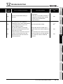
HOW THIS MANUAL IS ORGANIZED
Reference destination
Chapter heading
A reference destination or
The index on the right side of the page
reference manual is marked
shows the chapter of the open page at a
.
glance.
Section title
The section of the open page is shown at a
glance.
In addition, this manual provides the following explanations.
POINT
Explains the matters to be especially noted, the functions and others related to the
description on that page.
Remark
Provides the reference destination related to the description on that page and the
convenient information.
A - 21
HOW TO USE THIS MANUAL
This manual is prepared for users to understand the hardware specifications of those
modules such as the CPU modules, power supply modules, and base units, maintenance
and inspections of the system, and troubleshooting required when you use QS series
programmable controllers.
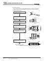
The manual is classified roughly into three sections as shown below.
1) Chapters 1 and 2
Describe the outline of the CPU module and the system
configuration.
The basics of the system configuration of CPU module are
described.
2) Chapters 3 to 7
Describe the general specifications indicating the operating
environments of the CPU module, power supply module, and base
units, and the performance specifications of these modules.
3) Chapters 8 to 12
Describe the overall maintenance such as the installation of the
CPU module, daily inspections, and troubleshooting.
Remark
This manual does not explain the functions of the CPU module.
For these functions, refer to the manual shown below.
QSCPU User's Manual (Function Explanation, Program Fundamentals)
A - 22
GENERIC TERMS AND ABBREVIATIONS
Unless otherwise specified, this manual uses the following generic terms and
abbreviations to explain the QS series CPU modules.
Generic Term/Abbreviation
Description
Generic term for safety CPU module, safety power supply module, safety main base
Safety programmable controller
unit, CC-Link safety master module, CC-Link safety remote I/O moduls, and CC-Link IE
Field Network master/local module (with safety functions).
Generic term of each module for MELSEC-Q series, MELSEC-L series, MELSEC-QnA
Standard programmable controller series, MELSEC-A series and MELSEC-FX series. (Used for distinction from safety
programmable controller.)
QS series
Abbreviation for Mitsubishi safety programmable controller MELSEC-QS series
QS001CPU
Abbreviation for the QS001CPU type safety CPU module
CPU module
GX Developer
Other name for the QS001CPU
General product name for the models SW8D5C-GPPW-E, SW8D5C-GPPW-EA,
SW8D5C-GPPW-EV and SW8D5C-GPPW-EVA
QS034B
Abbreviation for the QS034B type safety main base unit
Base unit
Other name for the QS034B
QS061P
Abbreviation for the QS061P-A1 and QS061P-A2 type safety power supply modules
Power supply module
Other name for the QS061P
QS0J61BT12
Abbreviation for the QS0J61BT12 type CC-Link Safety system master module
CC-Link Safety
Abbreviation for the CC-Link Safety system
CC-Link Safety master module
Other name for the QS061BT12
QS0J65BTS2-8D
Abbreviation for the QS0J65BTS2-8D CC-Link Safety system remote I/O module
QS0J65BTS2-4T
Abbreviation for the QS0J65BTS2-4T CC-Link Safety system remote I/O module
QS0J65BTB2-12DT
Abbreviation for the QS0J65BTB2-12DT CC-Link Safety system remote I/O module
CC-Link Safety remote I/O
module
Generic term for the QS0J65BTS2-8D, QS0J65BTS2-4T, and QS0J65BTB2-12DT
CC-Link IE Field Network master/
local module (with safety
Abbreviation for the MELSEC-QS series CC-Link IE Field Network master/local module
functions)
CC-Link IE Controller Network
Abbreviation for the QJ71GP21-SX and QJ71GP21S-SX CC-Link IE Controller Network
module
module
MELSECNET/H
MELSECNET/H module
Ethernet
Ethernet module
Abbreviation for the MELSECNET/H network system
Abbreviation for the QJ71LP21-25, QJ71LP21S-25, QJ71LP21G, QJ71BR11
MELSECNET/H network module
Abbreviation for the Ethernet network system
Abbreviation for the QJ71E71-100, QJ71E71-B5, QJ71E71-B2 Ethernet interface
module
Generic term for the CC-Link Safety master module, CC-Link IE Field Network master/
Intelligent function module
local module (with safety functions), CC-Link IE Controller Network module,
MELSECNET/H module, and Ethernet module
Generic term for the CC-Link IE Field Network master/local module (with safety
Network module
functions), CC-Link IE Controller Network module, MELSECNET/H module, and
Ethernet module
Battery
Blank cover
GOT
Abbreviation for the Q6BAT type battery
Abbreviation for the QG60 type blank cover
Generic term for the Mitsubishi Graphic Operation Terminal GOT-A*** series, GOT-F***
series and GOT1000 series
A - 23
PRECAUTIONS FOR USE
Precautions for the first use of the QS series CPU module
When using a CPU module for the first time, the PLC memory needs to be initialized
using GX Developer.
For details of PLC memory initialization, refer to the following manual.
GX Developer Operating Manual (Safety Programmable Controller)
Precautions on battery
(1) When running the CPU module that has been stored without battery
When, in the TEST MODE, running the CPU module that has been stored with the
battery removed, the memory needs to be formatted using GX Developer.
(
Section 11.4)
(2) When running the CPU module that has been stored with battery longer than
the battery life
When, in the TEST MODE, running the CPU module that has been stored with the
battery exceeding its life, the memory needs to be formatted using GX Developer.
(
A - 24
Section 11.5)
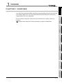
1
OVERVIEW
1
This manual describes the hardware specifications and handling methods of the QS series
CPU module, QS001CPU. The manual also describes the specifications of the power
supply module, base, unit, and battery.
2
SYSTEM
CONFIGURATION
For the functions, programs, and devices of the QS series CPU module, refer to the
following.
OVERVIEW
CHAPTER1 OVERVIEW
QSCPU User's Manual (Function Explanation, Program Fundamentals)
GENERAL
SPECIFICATIONS
3
CPU MODULE
4
POWER SUPPLY
MODULE
5
BASE UNIT
6
BATTERY
7
1-1
CPU MODULE STARTUP PROCEDURES
8
1
OVERVIEW
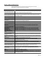
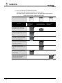
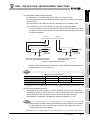
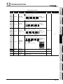
(1) List of QS Series CPU Module manuals
The QS series CPU module manuals are as shown below.
For details such as manual numbers, refer to "About Manuals" in this manual.
Table1.1 List of manuals of QS Series CPU module
Maintenance
and Inspection
Purpose
QSCPU User's Manual
(Hardware Design,
Maintenance and
inspection)
Program
Fundamentals
QSCPU User's Manual
(Function Explanation,
Program Fundamentals)
Common
Instructions
QSCPU Programming
Manual (Common
Instruction)
Confirmation of part names and
specifications of the CPU module
Details
Outline
Confirmation of connection methods
for the power supply module and base
Details
unit
Construction of the CPU system
(confirmation of start-up procedure
Details
and I/O number assignment)
Confirmation of the sequence program
Details
configuration and memory
Confirmation of the functions,
parameters, and devices of the CPU
Details
module
Confirmation of the troubleshooting
and error codes
Details
Confirmation of usage of sequence
instructions, basic instructions,
application instructions, etc.
1-2
Details
OVERVIEW
1
OVERVIEW
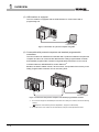
1.1 Features
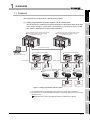
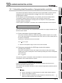
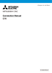
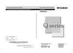
(1) Safety programmable controller system can be constructed
The QS series CPU module has acquired certification of the highest safety level (SIL3
of IEC 61508, Category 4 of EN 654-1, and Category 4 performance level "e" of EN
ISO 13849-1) applicable to programmable controllers.
Power supply/CPU/CC-Link Safety master module/
CC-Link IE Field Network master/local module
(with safety functions)*2
Power supply/CPU/CC-Link Safety master module/
CC-Link IE Field Network master/local module
(with safety functions)*2
2
SYSTEM
CONFIGURATION
The QS series CPU module has the following new features:
GENERAL
SPECIFICATIONS
3
CC-Link IE field network
CC-Link Safety remote I/O station
CPU MODULE
CC-Link Safety
CC-Link Safety remote I/O station
CC-Link Safety
Emergency stop
switch
Emergency stop
switch
Light curtain
Standard remote I/O
station
Standard remote
device station
CC-Link Safety
remote I/O station
Light curtain
CC-Link Safety
remote I/O station
POWER SUPPLY
MODULE
5
Emergency stop
switch
Safety relay
Figure 1.1 Safety programmable controller system
BASE UNIT
6
7
* 1 : The available functions vary depending on the versions. For details, refer to Appendix 2.
* 2 : For details of the CC-Link IE Field Network master/local module (with safety functions), refer to the
following manual.
MELSEC-QS CC-Link IE Field Network Master/Local Module User's Manual
BATTERY
GX Developer
(Version 8.40S or later)*1
4
8
1.1 Features
1-3
CPU MODULE STARTUP PROCEDURES
1
1
OVERVIEW
(2) The safety CPU operation mode is equipped for safe system operation
The CPU module is equipped with two safety CPU operation modes. "SAFETY
MODE" for safe system operation and "TEST MODE" for system construction and
maintenance.
These two modes prevent the user's erroneous operations for safe system operation.
(a) SAFETY MODE
SAFETY MODE is a mode for safe system operation. This mode prohibits the
write operation from a programming tool and the device test operation during the
system operation.
(b) TEST MODE
TEST MODE is a mode for maintenance. This mode enables the write operation
from a programming tool and the device test operation to debug or maintain the
sequence program.
For the details of operations available in the SAFETY MODE and TEST MODE, refer
to the following manual.
QSCPU User's Manual (Function Explanation, Program Fundamentals)
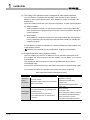
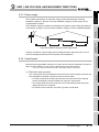
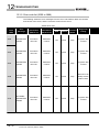
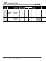
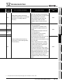
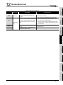
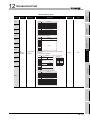
(3) Enriched operation history and error history
The CPU module can record up to 3000 logs of user operations performed on the
CPU module, and errors occurred in the CPU module, CC-Link Safety, or CC-Link IE
Field Network.
User operations and errors will be recorded as operation/error history data in
chronological order.
Checking the operation/error history data helps users perform troubleshooting easier.
The contents recorded in the operation/error history are shown in Table1.2.
Table1.2 Recorded contents of operation/error history
Information
Operation
history
information
Contents
User's operations for the CPU module are
stored as a history.
(Operations which change the CPU module
status are recorded.)
The following errors are stored as a history.
• Error/failure detected by self-diagnostics
Error history
• Hardware error
information
• Error detected in CC-Link Safety
• Error detected in the CC-Link IE Field
Network
1-4
1.1 Features
History Information per Entry
• Operation code
• Operation message
• Operation execution date
• Result code
• Operation attached information
• Error code
• Error message
• Occurrence date
• Error information category (common
information/individual information)
• Error information (common
information/individual information)
OVERVIEW
1
OVERVIEW
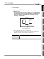
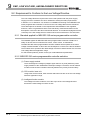
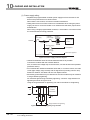
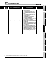
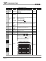
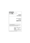
(4) Enhanced RAS
(b) Redundant CPU
The CPU module has two CPUs (CPU A and CPU B). The operation results of
CPU A/CPU B are compared, and output only when the results are matched so
that incorrect outputs can be prevented. (When the compared results are
mismatched, the system stops.)
CPU module
Operation
result
3
GENERAL
SPECIFICATIONS
CPU
A
CPU
B
Compare
2
SYSTEM
CONFIGURATION
(a) Enhanced memory diagnostics
The memory diagnostics equipped with the CPU module are enhanced.
4
Operation
result
CPU MODULE
Output when matched
Figure 1.2 Redundant CPU
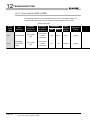
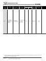
(c) Enhanced hardware diagnostics by hardware circuit
The diagnostic functions of the Table1.3 prevents incorrect outputs when a
5
Table1.3 Hardware diagnostics function added to the QS series CPU module
Diagnostics
Overvoltage/
Diagnosis Contents
Overvoltage or undervoltage is detected for the power supply voltage
provided from the power supply module to the CPU module.
Clock stop detection
The input clock stop to the CPU module internal circuit is detected.
6
BASE UNIT
undervoltage detection
POWER SUPPLY
MODULE
hardware error which cannot be detected by the OS occurs.
BATTERY
7
8
1.1 Features
1-5
CPU MODULE STARTUP PROCEDURES
1
1
OVERVIEW
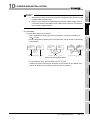
(5) USB interface is equipped
The CPU module is equipped with the USB interface to communicate with a
programming tool.
USB
Personal computer
Figure 1.3 Connection to a personal computer using USB
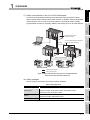
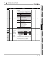
(6) Connectable with personal computers and standard programmable
controllers*1
The CPU module can read data from the MELSOFT products installed in the personal
computer and also can communicate data between safety programmable controller
and standard programmable controller using dedicated instructions via CC-Link IE
Controller Network, MELSECNET/H, and/or Ethernet*2.
Besides, the data of ladder monitor, device monitor, and operation/error history in the
safety programmable controller can be read using GOT.
Personal computer
Figure 1.4 Connection with personal computer and standard programmable controller
* 1 : For an access range from GX Developer and a GOT to a safety CPU module, refer to the following
manual.
QSCPU User's Manual (Function Explanation, Program Fundamentals)
* 2 : An access to the CPU module can be restricted by using the remote password function.
1-6
1.1 Features
OVERVIEW
1
2
SYSTEM
CONFIGURATION
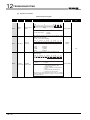
A CC-Link IE Field Network master/local module (with safety functions) enables
safety communication between safety CPU modules. In addition, safety and standard
communications can be used on the same network. These factors allow a safety
programmable controller to be simply added to the existing CC-Link IE Field Network.
OVERVIEW
(7) Safety communication in the CC-Link IE Field Network
CC-Link IE Field Network
master/local module
CC-Link IE Field Network master/local
module (with safety functions)
Standard
communication
Personal computer
GENERAL
SPECIFICATIONS
3
CPU MODULE
4
Safety communication
POWER SUPPLY
MODULE
5
: Standard communication
: Safety communication
Figure 1.5 Safety communication using the CC-Link IE Field Network
master/local module (with safety functions)
6
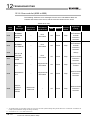
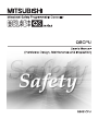
(8) Safety Standards
BASE UNIT
Use the product according to the following safety standards.
Table1.4 Safety Standards
Region
International
Safety Standards
IEC61508 Parts 1-7:1998-2000, ISO13849-1:2006,
7
IEC61131-2:2007, IEC61000-6-2:2005, IEC61000-6-4:2006,
IEC61784-3:2010, IEC60204-1:2006
North America
EN61000-6-2:2005, EN61000-6-4:2007
BATTERY
Europe
EN954-1:1996, EN ISO13849-1:2008, EN61131-2:2007,
UL508, NFPA79-2007
8
1.1 Features
1-7
CPU MODULE STARTUP PROCEDURES
1
2
SYSTEM CONFIGURATION
CHAPTER2 SYSTEM CONFIGURATION
This section describes the system configuration of the QS series CPU module cautions on
use of the system, and configured equipment.
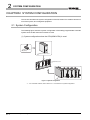
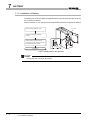
2.1 System Configuration
The following figure shows the system configuration of the safety programmable controller
system when the QS series CPU module is used.
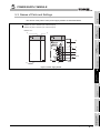
(1) System configuration when the CPU(QS001CPU) is used
Battery for a CPU
(Q6BAT)
QS001CPU CPU module
QS034B base unit
*1
Power supply/intelligent function module
Figure 2.1 System configuration
* 1 : For mountable modules, refer to Section 2.1.1 "Precautions for system configuration".
2-1
2.1 System Configuration
SYSTEM CONFIGURATION
1
OVERVIEW
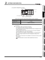
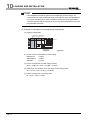
(2) System configuration overview
2
3
Slot number
30 to 3F
I/O number
2
SYSTEM
CONFIGURATION
1
Figure 2.2 System configuration
Table2.1 Base unit and power supply module applicable to system configuration
3
GENERAL
SPECIFICATIONS
4 modules
mountable modules
Power supply module model
QS061P-A1, QS061P-A2
Precautions
• The extension base unit cannot be connected.
• The multiple CPU system cannot be configured.
• The modules which can be mounted on the I/O slot are the intelligent function
module and blank cover only.
If a module other than the ones mentioned above is mounted, "MODULE
LAYOUT ERROR" (error code: 2125) is detected.
Note, however, that a "MODULE LAYOUT ERROR" is not detected for the
slot where "Empty" has been set in the I/O assignment setting of PLC
parameter.
• Bus connection for the GOT is not available. For the GOT connection, refer to
the following.
GOT1000 Series Connection Manual (Mitsubishi Products)
4
CPU MODULE
Maximum number of
QS034B
5
POWER SUPPLY
MODULE
Base unit model name
CPU module
BASE UNIT
6
BATTERY
7
8
2.1 System Configuration
2-2
CPU MODULE STARTUP PROCEDURES
Power supply module
name
0
20 to 2F
CPU
10 to 1F
Base unit (QS034B)
00 to 0F
2
2
SYSTEM CONFIGURATION
Table2.2 Safety programmable controller products
Product Name
Safety main base unit
Model
QS034B
QS034B-K
QS061P-A1
Safety power supply
module
Safety CPU module
QS061P-A2
module
A unit where a safety CPU module, safety power supply module,
and CC-Link Safety system master module are mounted
An S-mark*1 certified safety main base unit
A module which is mounted on a safety main base unit and
supplies 100VAC to the system
A module which is mounted on a safety main base unit and
supplies 200VAC to the system
QS061P-A1-K
An S-mark*1 certified safety power supply module (100VAC)
QS061P-A2-K
An S-mark*1 certified safety power supply module (200VAC)
QS001CPU
QS001CPU-K
CC-Link Safety master
Description
QS0J61BT12
QS0J61BT12-K
A module which is mounted on a safety main base unit and
performs logic operations for safety control
An S-mark*1 certified safety CPU module
A module which is mounted on a safety main base unit and
establishes connection to CC-Link Safety
An S-mark*1 certified CC-Link Safety master module
CC-Link IE Field
Network master/local
module (with safety
QS0J71GF11-T2
A module which is mounted on a safety main base unit and
establishes connection to CC-Link IE Field Network
functions)
* 1 : S-mark is a safety certification issued by Korea Occupational Safety and Health Agency (KOSHA).
2-3
2.1 System Configuration
2
SYSTEM CONFIGURATION
1
OVERVIEW
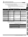
2.1.1 Precautions for system configuration
(1) Modules mountable on the main base unit
Table2.3 lists the modules that can be mounted on the main base unit.
The number of mounted modules and functions are restricted depending on the
module type.
2
Power supply module
CC-Link Safety master
module
• QS001CPU
Only one
• QS061P-A1
Only one (only one of the module
---
• QS061P-A2
models)
• QS0J61BT12
Up to two
---
• QS0J71GF11-T2
Only one
---
---
3
CC-Link IE Field Network
master/local module (with
safety functions)
CC-Link IE Controller Network
• QJ71GP21-SX
module
• QJ71GP21S-SX
MELSECNET/H module
• Serial number (first five digits):
“10041” or later
Only one (only one of the models
• QJ71LP21-25
among CC-Link IE Controller
• QJ71LP21S-25
Network modules and MELSECNET/
• QJ71LP21G
H modules)
• QJ71LP21GE
• Function version: D or later
• Serial number (first five digits):
“08102” or later
• Function version: D or later
• QJ71BR11
Only one (only one of the module
• QJ71E71-B5
• QG60
Up to four
---
(2) Module/Unit Replacement
Replace the module or unit according to the following replacement cycle.
6
Table2.4 Module/Unit Replacement
Replacement Cycle
Safety power supply module
5 years
Safety CPU module
10 years
Safety main base unit
10 years
CC-Link Safety master module
10 years
CC-Link IE Field Network master/local module (with
safety functions)
BASE UNIT
Module/Unit
10 years
7
BATTERY
Blank cover
5
---
models)
• QJ71E71-100
POWER SUPPLY
MODULE
• QJ71E71-B2
Ethernet module
4
CPU MODULE
CPU module
Remarks
mounted in one system
GENERAL
SPECIFICATIONS
Number of modules
Model
8
2.1 System Configuration
2.1.1 Precautions for system configuration
2-4
CPU MODULE STARTUP PROCEDURES
Module
SYSTEM
CONFIGURATION
Table2.3 Modules mountable on the main base unit
2
SYSTEM CONFIGURATION
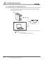
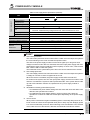
2.2 Configuration of Peripheral Devices
This section describes the configuration of the peripheral devices usable in the safety
programmable controller system.
QS001CPU
Personal computer
(GX Developer Version 8.40S or later)
USB cable*1
* 1: For details of the USB cable, refer to "About the USB cable (QCPU (Q mode) compatible)" of the
following manual.
GX Developer Operating Manual
Figure 2.3 Configuration of peripheral devices
2-5
2.2 Configuration of Peripheral Devices
2.1.1 Precautions for system configuration
SYSTEM CONFIGURATION
1
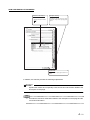
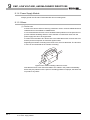
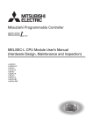
The serial number and function version of the CPU module can be checked on the rating
plate or the System monitor window in GX Developer.
OVERVIEW
2.3 Checking Serial Number and Function Version
2
(1) Checking on the rating plate
SYSTEM
CONFIGURATION
The rating plate is located on the side of the CPU module.
PASSED
3
MODEL
GENERAL
SPECIFICATIONS
Serial No. (first 5 digits)
function version
SERIAL 080910000000000-A
Standard symbol for
conformance is described.
4
CPU MODULE
MADE IN JAPAN
Figure 2.4 Rating plate
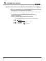
(2) Checking on the front of the module
QS001CPU
ALIVE
RUN
E R R.
5
POWER SUPPLY
MODULE
The serial number on the rating plate is printed on the front (at the bottom) of the
module.
TEST
USER
B A T.
6
BASE UNIT
PULL
USB
7
090911090910001-B
BATTERY
Serial No.
Figure 2.5 Display on the front of the module
8
2.3 Checking Serial Number and Function Version
2-6
CPU MODULE STARTUP PROCEDURES
2
2
SYSTEM CONFIGURATION
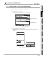
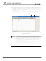
(3) Checking on the System monitor window (Product Information List window)
To display the window for checking the serial number and function version, select
[Diagnostics]
[System monitor] and click the Product Information List button in GX
Developer.
On the window, the serial number and function version of intelligent function modules
can also be checked.
Serial number function version
Figure 2.6 System monitor
POINT
The serial number displayed on the Product information list window of GX
Developer may differ from that on the rating plate and on the front of the module.
• The serial number on the rating plate indicates the management
information of the product.
• The serial number displayed on the Product Information List window
indicates the functional information of the product.
The functional information of the product is updated when a new function
is added.
2-7
2.3 Checking Serial Number and Function Version
3
GENERAL SPECIFICATIONS
1
OVERVIEW
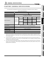
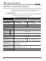
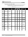
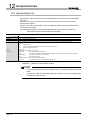
CHAPTER3 GENERAL SPECIFICATIONS
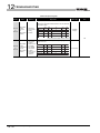
The performance specifications of QS series programmable controllers are shown in Table3.1.
Table3.1 General specifications
Item
Operating ambient temperature
5 to 95%RH, non-condensing
Constant
Half
5 to 8.4Hz
acceleration
----
amplitude
3.5mm
8.4 to 150Hz
9.8m/s2
----
5 to 8.4Hz
----
1.75mm
8.4 to 150Hz
4.9m/s2
----
Frequency
Compliant
Under
with JIS B
intermittent
3502 and
vibration
IEC 61131-2
Under
continuous
vibration
each in X, Y,
Z directions
----
Overvoltage category *1
*2
each in 3 directions X, Y, Z by sine half-wave pulse)
No corrosive gases
0 to 2000m
Inside a control panel
II or less
5
2 or less
Class I
: This indicates the section of the power supply to which the equipment is assumed to be connected between the public
electrical power distribution network and the machinery within premises. Category II applies to equipment for which
electrical power is supplied from fixed facilities. The surge voltage withstand level for equipment with the rated voltage
of up to 300V is 2500V.
*2
4
CPU MODULE
Operating
Installation location
3
: This index indicates the degree to which conductive material is generated in terms of the environment in which the
POWER SUPPLY
MODULE
altitude*3
*1
10 times
Conforming to JIS B 3502 and IEC 61131-2 (147 m/s2, duration of action 11ms, 3 times
Operating atmosphere
Pollution degree
Equipment class
Sweep count
GENERAL
SPECIFICATIONS
-40 to 75
Operating ambient humidity
Storage ambient humidity
Shock resistance
SYSTEM
CONFIGURATION
0 to 55
Storage ambient temperature
Vibration resistance
2
Specifications
6
equipment is used. Pollution level 2 is when only non-conductive pollution occurs. A temporary conductivity caused by
: Do not use or store the programmable controller under pressure higher than the atmospheric pressure of altitude 0m.
Doing so may cause malfunction. When using the programmable controller under pressure, please consult your local
Mitsubishi Electric representative.
BASE UNIT
condensing may be expected occasionally.
BATTERY
7
8
3-1
CPU MODULE STARTUP PROCEDURES
*3
3
GENERAL SPECIFICATIONS
Memo
3-2
4
CPU MODULE
1
OVERVIEW
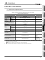
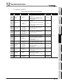
CHAPTER4 CPU MODULE
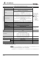
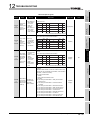
4.1 Performance Specifications
2
Table4.1 shows the performance specifications of the CPU module.
instruction)
Constant scan
MOV D0 D1
(Function for keeping regular scan
time)
0.10 s
----
0.35 s
----
1 to 2000ms
(in increments of 1ms)
----
128K bytes
----
128K bytes
----
Program memory
3*2
----
Standard ROM
3*2
----
Max.100000 times
----
Memory
(drive 0)
capacity*1
Standard ROM
(drive 4)
No. of times of writing data into the
standard ROM
3
Setting by parameters.
(56K bytes)
Program memory
files stored
----
14K steps
Program capacity *1
Max. number of
Relay symbol language, function block.
4
5
No. of points
No. of I/O device points
6144 points(X/Y0 to 17FF)
usable on
program
No. of points
No. of I/O points
1024 points(X/Y0 to 3FF)
GENERAL
SPECIFICATIONS
(sequence
language
LD X0
Remarks
-------
CPU MODULE
language
Processing speed
QS001CPU
Repetitive operation of stored program
Refresh mode
POWER SUPPLY
MODULE
Program
Item
Control method
I/O control mode
Sequence control
SYSTEM
CONFIGURATION
Table4.1 Performance Specifications
accessible to the
6
actual I/O module
: The maximum number of executable sequence steps is as shown below.(Program capacity) - (File header size (default: 34 steps))
BASE UNIT
For the details, refer to the manual below.
QSCPU User's Manual (Function Explanation, Program Fundamentals)
: Each of parameter, sequence program, SFC program, and device comment files can be stored.
7
BATTERY
*2
8
4.1 Performance Specifications
4-1
CPU MODULE STARTUP PROCEDURES
*1
4
CPU MODULE
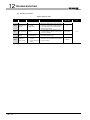
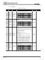
Table4.1 Performance Specifications (Continue)
Item
QS001CPU
Internal relay [M]
6144 points by default (M0-6143) (changeable)
Link relay [B]
2048 points by default (B0 to 7FF) (changeable)
Remarks
512 points by default (T0 to 511) (changeable)
(Sharing of low- and high-speed timers)
The low- and high-speed timers are specified by the instructions.
Timer [T]
The measurement unit of the low- and high-speed timers is set up by
parameters.
(Low-speed timer: 1 to 1000ms, 1ms unit, 100ms by default)
(High-speed timer: 0.1 to 100ms, 0.1ms unit, 10ms by default)
No. of device points
0 point by default
(sharing of the low- and high-speed retentive timers) (changeable)
The low- and high-speed retentive timers are specified
Retentive timer [ST]
by the instructions.
The measurement unit of the low- and high-speed retentive timers
is set up by parameters.
(Low-speed retentive timer: 1 to 1000ms, 1ms unit, 100ms by default)
The number of points
can be changed within
the setting range.
(
QSCPU User's
Manual
(Function
Explanation,
Program
Fundamentals)
(High-speed retentive timer: 0.1 to 100ms, 0.1ms unit, 10ms by default)
Counter [C]
Normal counter: 512 points by default (C0 to 511) (changeable)
Data register [D]
6144 points by default (D0 to 6143) (changeable)
Link register [W]
2048 points by default (W0 to 7FF) (changeable)
Annunciator [F]
1024 points by default (F0 to 1023) (changeable)
Edge relay [V]
1024 points by default (V0 to 1023) (changeable)
Link special relay [SB]
1536 points (SB0 to 5FF)
Link special register [SW]
1536 points (SW0 to 5FF)
Special relay [SM]
5120 points (SM0 to 5119)
Special register [SD]
The number of device
points is fixed.
5120 points (SD0 to 5119)
One contact can be set up in X0 to 17FF for each of RUN. No PAUSE
RUN/PAUSE contact
contact.
Setting by parameters.
Year, month, date, hour, minute, second and day-of-week
(leap year automatically identified)
Accuracy: -3.18 to +5.25s (TYP.+2.14s)/d at 0
Timer function
----
Accuracy: -3.18 to +2.59s (TYP.+2.07s)/d at 25
Accuracy: -12.97 to +3.63s (TYP.-3.16s)/d at 55
Allowable instantaneous power failure
period
Varies depending on the power supply module.
0.58A*3
----
H
98mm (3.86 inch)
----
W
55.2mm (2.17 inch)
----
D
114mm (4.49 inch)
----
0.29kg
----
IP2X
----
5VDC internal current consumption
External dimensions
Weight
Protection of degree
*3
: The value for the CPU module whose serial number (first four digits) is "1207" or earlier is 0.43A.
5VDC internal current consumption: 0.43A
Remark
For the general specifications, refer to CHAPTER 3.
4-2
----
4.1 Performance Specifications
CPU MODULE
1
1)
QS001CPU
ALIVE
RUN
ERR.
4)
TEST
USER
BAT.
5)
3)
6)
7)
ALIVE
RUN
ERR.
13)
2
TEST
USER
BAT.
SYSTEM
CONFIGURATION
1)
2)
OVERVIEW
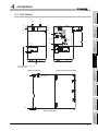
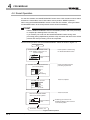
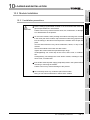
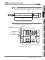
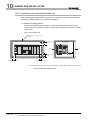
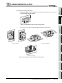
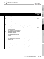
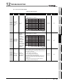
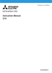
4.2 Part Names
BAT.
14)
3
PULL
STOP
10)
PULL
USB
GENERAL
SPECIFICATIONS
RESET RUN
9)
CPU MODULE
4
15)
When opening the cover, put
your finger here.
5
Figure 4.2 With front cover open
POWER SUPPLY
MODULE
Figure 4.1 Front face
11)
BASE UNIT
6
BATTERY
7
12)
8)
Figure 4.3 Side Face
8
4.2 Part Names
4-3
CPU MODULE STARTUP PROCEDURES
4
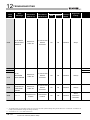
4
CPU MODULE
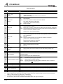
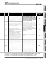
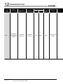
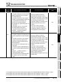
Table4.2 Part Names
No.
Name
1) Module fixing hook
"ALIVE" LED
2)
(Green)
"TEST" LED
3)
Application
Hook used to fix the module to the base unit.
On
Off
: Normal*1
: When the hardware watchdog timer error is detected
("ERR." LED is On.)
Indicates the operating mode of the CPU module.
On
: TEST MODE *1
Flash : When TEST MODE is switched to SAFETY MODE
The "TEST" LED turns off after reset.
(Yellow)
Off
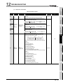
Indicates the operating status of the CPU module.
On
: During operation in "RUN"*1
Off
: During stop in "STOP" or when the error which stops the operation is detected
Flash : When parameters/program is written during STOP and the RUN/STOP/RESET
"RUN" LED
4)
(Flash interval: On 200ms/Off 200ms)
: SAFETY MODE
(Green)
switch is moved from "STOP" to "RUN"
(Flash interval: On 200ms/Off 200ms)
On
"ERR." LED
5)
(Red)
: When the self-diagnostics error that will not stop operation, other than a battery
error, is detected *1
Off
: Normal
Flash : When the self-diagnostics error that will stop operation is detected
(Flash interval: On 200ms/Off 200ms)
When the reset operation is performed
(Flash interval: On 60ms/Off 60ms)
"USER" LED
6)
(Red)
"BAT." LED
7)
(Yellow)
On
Off
: When the annunciator (F) turns ON*1
: Normal
On
Off
: When a battery error has occurred due to the CPU battery voltage drop *1
: Normal
8)
Module loading lever
Used to load the module to the safety base unit.
Connector used to connect to the USB compatible peripheral devices.
9)
USB connector*2
(Connector type B)
Can be connected by the USB dedicated cable.
10) RUN/STOP/RESET switch*3
RUN
STOP
RESET
11) Module fixing screw
12) Module fixing latch
13) Battery
error occurs. (
Section 4.4)
Screw used to fix a module to the base unit. (M3 screw)
Latch used to fix a module to the base unit.
Backup battery for the power failure compensation function of program memory.
For connection of the battery lead wires (When shipped from the factory, the lead wires
14) Battery connector pin
15) Serial number display
*1
*2
*3
: Executes sequence program operation.
: Stops sequence program operation.
: Performs hardware reset and operation initialization when an operation
are disconnected from the connector to prevent the battery from discharging.)
Displays the serial number on the rating plate.
: Turns On during the initial processing (self-diagnostics, etc.) right after the power-on or reset cancel.
: When a cable is to be connected to the USB connector at all times, clamp the cable to prevent a loose connection,
shifting, or disconnection by pulling due to carelessness.
: Operate the RUN/STOP/RESET switch with your fingertips.
Do not use any tool such as a screwdriver because the switch part might be damaged.
4-4
4.2 Part Names
CPU MODULE
1
OVERVIEW
4.3 Switch Operation after Writing a Program
(a) Set the RUN/STOP/RESET switch to STOP.
The "RUN" LED turns Off, and the module is placed in the STOP status.
Write a program from GX Developer to the CPU module in the STOP status.
(b) Reset with the RUN/STOP/RESET switch.
The CPU module is reset. (
Section 4.4)
(c) Set the RUN/STOP/RESET switch to RUN.
The "RUN" LED turns on, and the CPU module is placed in the RUN status.
(2) When writing a program during RUN
When writing a program during RUN, the operation for the RUN/STOP/RESET switch
is not required.
3
QSCPU User's Manual (Function Explanation, Program Fundamentals)
2. To stop the CPU module, the remote operation of GX Developer can also be
used.
In this case, the operation for the RUN/STOP/RESET switch is not required.
For details on the remote operation of GX Developer, refer to the following
manual.
5
POWER SUPPLY
MODULE
The program modified online during boot operation is written to the program
memory.
After making online program change, also write the program to the standard
ROM of the boot source memory. If the program is not written in the standard
ROM, the old program will be executed at the next boot operation.
For details of the boot operation, refer to the manual below.
CPU MODULE
4
POINT
1.
2
SYSTEM
CONFIGURATION
(1) When writing a program with the CPU module set to "STOP"
GENERAL
SPECIFICATIONS
Programs can be written to the CPU module in either the STOP or RUN status.
6
BASE UNIT
GX Developer Version 8 Operating Manual
BATTERY
7
8
4.3 Switch Operation after Writing a Program
4-5
CPU MODULE STARTUP PROCEDURES
4
4
CPU MODULE
4.4 Reset Operation
For the CPU module, the RUN/STOP/RESET switch of the CPU module is used to switch
between the "RUN status" and "STOP status" and to perform "RESET operation".
When using the RUN/STOP/RESET switch to reset the CPU module, moving the RUN/
STOP/RESET switch to the reset position will not reset it immediately.
POINT
Hold the RUN/STOP/RESET switch in the RESET position until reset processing
is complete (the flashing ERR. LED turns off).
If you release your hand from the RUN/STOP/RESET switch during reset
processing (during rapid flashing of ERR. LED), the switch will return to the STOP
position and reset processing cannot be completed.
Perform reset operation with the RUN/STOP/RESET switch as shown in Figure 4.4.
Start
Hold the RUN/STOP/RESET switch
in the "RESET" position (for one
second or longer).
.......................Reset operation is started using
the RUN/STOP/RESET switch.
STOP
RESET RUN
RUN/STOP/RESET
switch
The ERR. LED flashes several times
(3 to 4 times) rapidly.
ALIVE
RUN
ERR.
.......................Reset is accepted and reset
processing is performed.
TEST
USER
BAT.
flashing
Reset is completed.
The "ERR. LED" turns off .
ALIVE
RUN
ERR.
TEST
USER
BAT.
Off.
Return the RUN/STOP/RESET
switch to the "STOP" position.
STOP
RESET RUN
RUN/STOP/RESET
switch
.......................Reset is canceled.
:
Releasing your hand from the
RUN/STOP/RESET switch returns it
to the STOP position.
Termination , completed , end
Figure 4.4 Reset Operation
4-6
4.4 Reset Operation
CPU MODULE
1
POINT
OVERVIEW
Operate the RUN/STOP/RESET switch with your fingertips.
Do not use any tool such as a screwdriver because the switch part might be
damaged.
SYSTEM
CONFIGURATION
2
GENERAL
SPECIFICATIONS
3
CPU MODULE
4
POWER SUPPLY
MODULE
5
BASE UNIT
6
BATTERY
7
8
4.4 Reset Operation
4-7
CPU MODULE STARTUP PROCEDURES
4
5
POWER SUPPLY MODULE
CHAPTER5 POWER SUPPLY MODULE
This section describes the specifications of the power supply modules applicable for the
programmable controller system and how to select the most suitable module.
5.1 Specifications
Table5.1 shows the specifications of the power supply modules.
Table5.1 Power supply module specifications
Performance Specifications
Item
QS061P-A1
Base loading position
Applicable base unit
QS061P-A2
QS series power supply module loading slot
QS034B
+10%
+10%
100 to 120VAC -15%
Input power supply
200 to 240VAC -15%
(85 to 132VAC)
(170 to 264VAC)
Input frequency
50/60Hz
Input voltage distortion ratio
Within 5% (
Max. input apparent power
5%
Section 5.2)
125VA
20A, 8ms or less*4
Inrush current
Rated output
current
Overcurrent
protection*1
Overvoltage
5VDC
6A
5VDC
6.6A or more
5VDC
protection*2
Efficiency
Allowable momentary power
5.5 to 6.5V
70% or more
Within 20ms
failure period*3
1780VAC rms/3 cycles between all inputs
2830VAC rms/3 cycles between all inputs
and LG and all outputs and FG (2000 m
and LG and all outputs and FG
(6562 ft.) above sea level)
(2000 m (6562 ft.) above sea level)
Withstand voltage
10M
Insulation resistance
or higher (500VDC insulation resistance tester) between:
• all inputs and LG and all outputs and FG
• all inputs and LG
• all outputs and FG
• Noise voltage 1500Vp-p, noise width 1 s, noise frequency 25 to 60Hz (noise
Noise immunity
simulator condition)
• Noise voltage IEC61000-4-4: 2kV
Operation indication
Fuse
5-1
5.1 Specifications
LED indication (Normal: On (green), Error: Off)
Built-in (Unchangeable by user)
5
POWER SUPPLY MODULE
1
Table5.1 Power supply module specifications (Continue)
Performance Specifications
24VDC, 0.5A
2
5VDC, 1mA
ON: 10ms or less, ON
OFF: 12ms or less
SYSTEM
CONFIGURATION
OFF
Mechanical : 20 million times or more
Life
Electrical : Rated switching voltage/current load: 100 thousand times or more
No
No
M3.5
Surge suppressor
Fuse
Terminal screw size
3
0.75 to 2mm2
Applicable solderless terminal
Applicable tightening torque
H
External
W
dimensions
D
Weight
RAV1.25 to 3.5, RAV2 to 3.5 (0.8mm or less thick)
0.66 to 0.89N•m
98mm (3.86 inch)
GENERAL
SPECIFICATIONS
Applicable wire size
55.2mm (2.17 inch)
115mm (4.53 inch)
0.40kg
4
POINT
*1: Overcurrent protection
The overcurrent protection function shuts off the 5 VDC circuit and stops the system if
the current flowing in the circuit exceeds the specified value.
The LED of the power supply module is turned off or lights up in dim green when
voltage is lowered. If this device is activated, switch the input power supply OFF and
eliminate the cause such as insufficient current capacity or short. Then, a few minutes
later, switch it ON to restart the system.
The initial start for the system takes place when the current value becomes normal.
*2: Overvoltage protection
The overvoltage protection function shuts off the 5 VDC circuit and stops the system if
a voltage of 5.5 VDC or above is applied to the circuit.
When this device is activated, the power supply module LED is turned OFF.
For restart of the system, turn OFF the input power supply, and then turn ON in a few
minutes. This allows the system to start up with initial start. If the system doesn't start
up and a LED indication remains off, replacement of a power supply module is
required.
*3: Allowable momentary power failure period
• An instantaneous power failure lasting less than 20ms will cause AC down to be
detected, but operation will continue.
• An instantaneous power failure lasting in excess of 20ms may cause the
operation to continue or initial start to take place depending on the power supply
load.
*4: Inrush current
When power is switched on again immediately (within 5 seconds) after power-off, an
inrush current of more than the specified value (2ms or less) may flow. Reapply power
5 or more seconds after power-off. When selecting a fuse and breaker in the external
circuit, take account of the blowout, detection characteristics and above matters.
5.1 Specifications
5-2
CPU MODULE
Response time
5
POWER SUPPLY
MODULE
voltage/current
Min. switching load
6
BASE UNIT
Rated switching
Section 5.3)
7
BATTERY
Contact output part
QS061P-A2
ERR. contact (
OVERVIEW
QS061P-A1
Application
8
CPU MODULE STARTUP PROCEDURES
Item
5
POWER SUPPLY MODULE
5.2 Precaution when connecting the uninterruptible power supply
Be sure of the following terms when connecting the QS Series CPU Module system to the
uninterruptible power supply (abbreviated as UPS hereafter):
Use an online UPS (uninterruptible power supply) with power distortion factor of 5% or
less or line-interactive UPS. For a standby system UPS, use Mitsubishi small-capacity
UPS "FREQUPS FW-F series" (hereafter abbreviated as FW-F series).*1
(Example: FWF10-0.3K/0.5K)
Do not use any standby system UPS other than the FW-F series.
* 1: Use a FW-F series UPS with the serial number starts with P or later or ends with HE.
Starts with "P" or later
Ends with "HE"
5-3
5.2 Precaution when connecting the uninterruptible power supply
POWER SUPPLY MODULE
1
OVERVIEW
5.3 Names of Parts and Settings
The names of the parts of each power supply module are described below.
QS061P-A1 (100 to 120VAC input, 5VDC 6A output)
QS061P-A2 (200 to 240VAC input, 5VDC 6A output)
2
7)
SYSTEM
CONFIGURATION
<QS061P-A1>
1)
3
GENERAL
SPECIFICATIONS
6)
2)
3)
4)
4
5)
Figure 5.1 Power supply module
POWER SUPPLY
MODULE
5
BASE UNIT
6
7
BATTERY
8)
CPU MODULE
9),10)
8
5.3 Names of Parts and Settings
5-4
CPU MODULE STARTUP PROCEDURES
5
5
POWER SUPPLY MODULE
Table5.2 Part names
No.
Name
Application
On (green) : Normal (5VDC output, instantaneous power failure within 20ms)
Off
: • AC power supply is ON, however, the power supply module is out of
order.
1)
"POWER" LED
(5VDC error, overload, internal circuit failure, fuse blown)
• AC power supply is not ON.
• Power failure (including an instantaneous power failure of 20ms or
more)
• Turned ON when the whole system operates normally.
2)
ERR. terminal
• Turns OFF (opens) when the AC power is not input, a stop error (including a reset)
3)
FG terminal
4)
LG terminal
5)
6)
Terminal screw
Terminal cover
7)
Module fixing screw
8)
9)
10)
Module loading lever
Power input terminal
Power input terminal
occurs in the CPU module, or the fuse is blown.
Ground terminal connected to the shielding pattern of the printed-circuit board.
Grounding for the power filter. The potential of the QS061P-A1 and QS061P-A2 terminals are one-half of the input voltage.
M3.5 screw
Protective cover of the terminal block
Used to fix the module to the base unit.
M3 screw (Tightening torque range : 0.36 to 0.48N•m)
Used to load the module to the base unit.
Power input terminal for the QS061P-A1 and connected to a 100VAC power supply.
Power input terminal for the QS061P-A2 and connected to a 200VAC power supply.
POINT
1.
The QS061P-A1 is dedicated for inputting a voltage of 100 VAC.
Do not input a voltage of 200 VAC into it or trouble may occur on the
QS061P-A1.
Table5.3 Precaution
Power module
Supply power voltage
100VAC
type
QS061P-A1
Operates normally.
200VAC
Power supply module causes
trouble.
Power supply module does not
QS061P-A2
cause trouble.
CPU module cannot be
Operates normally.
operated.
2.
3.
5-5
Individually ground the LG and FG terminals with a ground resistance of 100
or less.
ERR. terminal cannot be used as a safety output.
Connect the cable for ERR. contact of 30m or less in length in a control panel.
5.3 Names of Parts and Settings
6
BASE UNIT
1
This section describes the specifications of the base units used in the programmable
controller system.
The base unit is a unit to which the CPU module, power supply module and/or intelligent
function module are installed.
Table6.1 Base unit specifications
3
Type
GENERAL
SPECIFICATIONS
QS034B
4
Possibility of extension
Disable
QS series modules
5 VDC internal current consumption
0.10A
M4 screw hole or
4.5 hole (for M4 screw)
245mm (9.65 inch)
D
44.1mm (1.74 inch)
Attachment
DIN rail mounting Adapter type
CPU MODULE
W
Weight
4
98mm (3.86 inch)
0.28kg
Mounting screw M4 14 4 pieces (DIN rail mounting adapter to be sold separately)
Q6DIN2
5
POWER SUPPLY
MODULE
H
6
BASE UNIT
Mounting hole size
7
BATTERY
Applicable module
8
6.1 Specification
6-1
CPU MODULE STARTUP PROCEDURES
Number of I/O modules installed
External dimensions
SYSTEM
CONFIGURATION
2
6.1 Specification
Item
OVERVIEW
CHAPTER6 BASE UNIT
6
BASE UNIT
6.2 Part Names
The names of the parts of the base unit are described below.
4)
3)
OUT
a1
1)
POWER
b1
CPU
I/O0
I/O1
I/O2
I/O3
MODEL
SERIAL
PASSED
MADE IN JAPAN
2)
BD992C202H01
5)
Figure 6.1 Base unit (QS034B)
Table6.2 Part Names
No.
1)
Name
Base cover
Application
Cover for protecting the printed-circuit board of the base unit
Connector for installing the QS series power supply module, CPU module and
2)
Module connector
intelligent function module.
For the reserved connector where no module is mounted, attach a supplied
connector cover or a blank cover (QG60) to prevent entry of dust.
3)
4)
5)
6-2
Module fixing screw hole
Screw hole for fixing the module to the base unit. Screw size: M3 12
Base mounting hole
Hole for mounting this base unit onto the panel of the control panel (for M4 screw)
DIN rail adapter mounting hole Hole for mounting DIN rail adapter
6.2 Part Names
7
BATTERY
1
This section describes the specifications of the batteries available for the QS series CPU
module and how to handle them.
Batteries (Q6BAT) are installed in the CPU module to retain data of the program memory
and operation/error history in case of power failure.
7.1.1 Battery Specifications
3
GENERAL
SPECIFICATIONS
This section describes the specifications of the battery used for the CPU module.
Table7.1 Battery Specifications
used
Lithium content
Application
CPU MODULE
Battery life when
4
Actually 5 years (room temperature)
Section 11.3.1.
5
0.49g
Power failure backup for program memory, operation/error history
POWER SUPPLY
MODULE
stored
Type
Q6BAT
Manganese dioxide lithium primary battery
3.0V
1800mAh
Remark
1. Refer to Section 11.3.1 for the battery life.
2. For the battery directive in EU member states, refer to Appendix 4.
BASE UNIT
6
BATTERY
7
8
7.1 Battery (Q6BAT)
7.1.1 Battery Specifications
7-1
CPU MODULE STARTUP PROCEDURES
Classification
Initial voltage
Nominal current
Battery life when
SYSTEM
CONFIGURATION
2
7.1 Battery (Q6BAT)
Item
OVERVIEW
CHAPTER7 BATTERY
7
BATTERY
7.1.2 Installation of Battery
The battery for the CPU module is shipped with its connector disconnected. Connect
the connector as follows.
Refer to Section 11.3 for the service life of the battery and how to replace the battery.
CPU module
Open the CPU module front cover.
Confirm that the battery is loaded
correctly.
BAT.
PULL
Insert the battery connector into the
connector pin on the case. Be sure that
the insertion direction is correct.
BAT.
Connector
Completed
Figure 7.1 Q6BAT battery setting procedure
POINT
Firmly push the connector all the way.
7-2
7.1 Battery (Q6BAT)
7.1.2 Installation of Battery
STOP
RESET
RUN
8
CPU MODULE START-UP PROCEDURES
1
OVERVIEW
CHAPTER8 CPU MODULE START-UP PROCEDURES
This chapter describes the procedure for starting up the CPU module.
It is assumed that programs and parameters have been created separately.
2
SYSTEM
CONFIGURATION
8.1 Procedure before Operating in SAFETY MODE
This section describes the procedure before operating the CPU module in SAFETY
MODE.
The default operation mode of the CPU module is TEST MODE. Switch the mode to
SAFETY MODE to operate the CPU module.
GENERAL
SPECIFICATIONS
3
Start
Installing a base unit
•••
CHAPTER 10
•••
CHAPTER 2,
CHAPTER 10
•••
CHAPTER 10
•••
CHAPTER 10
•••
CHAPTER 4
MELSECNET/H
Network System
Reference Manual
(PLC to PLC network)
4
Install a base unit to a panel.
Fixing modules by screws
CPU MODULE
Install modules required for the system configuration to the base unit.
Fix the modules to the base unit with screws to prevent the displacement by vibrations or
other causes.
Wiring
5
Making initial settings of modules
1) Set the RUN/STOP/RESET switch of the CPU module to the STOP position.
(Set the CPU module to stop status.)
2) Make switch settings for the MELSECNET/H module.
POWER SUPPLY
MODULE
1) Wire the power supply to the power supply module.
2) Install wiring between the CC-Link Safety master module and the CC-Link Safety remote
I/O module.
3) Wire external device(s) to the CC-Link Safety remote I/O module.
4) Install wiring between network modules.
(To the next page)
6
BASE UNIT
Installing modules
BATTERY
7
8.1 Procedure before Operating in SAFETY MODE
8-1
CPU MODULE STARTUP PROCEDURES
8
8
CPU MODULE START-UP PROCEDURES
(Continued from the previous page)
Installing a battery
•••
CHAPTER 7
•••
CHAPTER 4,
CHAPTER 5,
CHAPTER 10
•••
CHAPTER 4
•••
GX Developer Version 8
Operating Manual
(Safety Programmable
Controller)
•••
GX Developer Version 8
Operating Manual
(Safety Programmable
Controller)
•••
GX Developer Version 8
Operating Manual
(Safety Programmable
Controller)
•••
GX Developer Version 8
Operating Manual
GX Developer Version 8
Operating Manual
(Safety Programmable
Controller)
•••
GX Developer Version 8
Operating Manual
•••
CHAPTER 4
•••
CHAPTER 4
•••
CHAPTER 4
Install a battery to the CPU module.
Powering ON the power supply module
Confirm the following items of the safety programmable controller system, and then turn on
the power supply.
Wiring of the power supply
Power supply voltage
Operating status of the CPU module
Stop status (The RUN/STOP/RESET switch is
in the STOP position.)
Confirming the CPU module LEDs
Confirm that the "ALIVE" LED and "TEST" LED of the CPU module are on.
(Confirm that the CPU module is in TEST MODE.)
Connecting a personal computer in which GX Developer is installed
1) Start up GX Developer on the personal computer in which GX Developer is installed.
2) Connect the personal computer with GX Developer installed, to the CPU module.
Initializing the PLC memory of the CPU module
Initialize the PLC memory of the CPU module with GX Developer.
Registering the CPU access password with the CPU module
Register the CPU access password with the CPU module by using GX Developer.
Setting clock data and clearing history data of the CPU module
When the safety CPU module is operated for the first time after purchase, take the following
actions for the CPU module with GX Developer.
Set the clock with "Clock setup".
Clear the error history of the CPU module with "PLC diagnostics".
1
Writing the parameters and programs to the CPU module
Write the parameters and user programs created by GX Developer to the CPU module.
Restarting the system
Turn off and then turn on the system power supply, or reset the CPU module.
Running the CPU module
Set the RUN/STOP/RESET switch of the CPU module to the RUN position.
Confirm that the "ALIVE" LED, "RUN" LED, and "TEST" LED of the CPU module are on.
Checking the user program operation
Check the user program operation, cables, and inputs/outputs.
When the "ERR." LED of the CPU module is on or flashing, identify the error cause by the
diagnostics*2 of GX Developer to eliminate the error cause.
When the error is related to the parameters or programs, correct them.
(To the next page)
* 2: The following types of diagnostics are available.
• PLC diagnostics
• Ethernet diagnostics
• CC IE Control diagnostics
• CC IE Field diagnostics
• MELSECNET diagnostics
• CC-Link / CC-Link/LT diagnostics
• System monitor
8-2
8.1 Procedure before Operating in SAFETY MODE
8
CPU MODULE START-UP PROCEDURES
1
•••
CHAPTER 4
•••
GX Developer Version 8
Set the RUN/STOP/RESET switch of the CPU module to the STOP position.
Switching to SAFETY MODE
Operating Manual
Switch the mode from TEST MODE to SAFETY MODE by selecting the menu option,
"Switch safety CPU operation mode", in GX Developer.
Confirming the CPU module LEDs
(Safety Programmable
Controller)
•••
CHAPTER 4
•••
CHAPTER 4
•••
CHAPTER 4
After the operation mode has been switched from TEST MODE to SAFETY MODE using
GX Developer, confirm that the "TEST" LED of the CPU module is flashing while the
"ALIVE" LED is on.
Restarting the system
3
GENERAL
SPECIFICATIONS
Turn the system power supply OFF and then ON, or perform the reset operation on the
CPU module.
Running the CPU module
2
SYSTEM
CONFIGURATION
Stopping the CPU module
OVERVIEW
(Continued from the previous page)
Set the RUN/STOP/RESET switch of the CPU module to the RUN position.
Confirm that the "ALIVE" LED and "RUN" LED of the CPU module are on, and the "TEST"
LED is off.
4
YES
CPU MODULE
Correct the program?
NO
End
•••
CHAPTER 4
•••
GX Developer Version 8
Set the RUN/STOP/RESET switch of the CPU module to the STOP position.
Switching to TEST MODE
Operating Manual
Switch the mode from SAFETY MODE to TEST MODE by selecting the menu option,
"Switch safety CPU operation mode", in GX Developer.
(Safety Programmable
•••
Confirming the CPU module LEDs
Controller)
CHAPTER 4
After the operation mode has been switched from SAFETY MODE to TEST MODE using
GX Developer, confirm that both the "TEST" LED and "ALIVE" LED of the CPU module are on.
•••
Correcting the program
GX Developer Version 8
Operating Manual
Correct the program with GX Developer.
6
BASE UNIT
Stopping the CPU module
POWER SUPPLY
MODULE
5
7
BATTERY
1
8.1 Procedure before Operating in SAFETY MODE
8-3
CPU MODULE STARTUP PROCEDURES
8
9
EMC, LOW VOLTAGE, AND MACHINERY DIRECTIVES
CHAPTER9 EMC, LOW VOLTAGE, AND MACHINERY
DIRECTIVES
Compliance with the Machinery Directive, which is one of the EU directives, has been
mandatory for the products sold within EU member states since 1995, as well as
compliance with the EMC Directive since 1996 and compliance with the Low Voltage
Directive since 1997.
The safety programmable controller is a CE-marked product. To prove the compliance,
Mitsubishi has issued an EC Declaration of Conformity for each EMC, Low Voltage, and
Machinery Directive, based on the safety approval obtained from the third-party
certification organization, TUV Rheinland .
(1) Authorized representative in Europe
Authorized representative in Europe is shown below.
Name : Mitsubishi Electric Europe BV
Address: Gothaer strasse 8, 40880 Ratingen, Germany
9.1 Requirements for Conformance to EMC Directive
The EMC Directive specifies that products placed on the market must "be so constructed
that they do not cause excessive electromagnetic interference (emissions) and are not
unduly affected by electromagnetic interference (immunity)".
The applicable products are requested to meet these requirements. The Section 9.1.1
through Section 9.1.5 summarize the precautions on conformance to the EMC Directive of
the machinery constructed using the MELSEC-QS series programmable controllers.
The details of these precautions has been prepared based on the control requirements
and the applicable standards control. However, we will not assure that the overall
machinery manufactured according to these details conforms to the above-mentioned
directives. The method of conformance to the EMC Directive and the judgment on whether
or not the machinery conforms to the EMC Directive must be determined finally by the
manufacturer of the machinery.
9-1
9.1 Requirements for Conformance to EMC Directive
9
EMC, LOW VOLTAGE, AND MACHINERY DIRECTIVES
9
EMC AND LOW
VOLTAGE
DIRECTIVES
9.1.1 Standards relevant to the EMC Directive
(1) Emission related standards
Table9.1 Emission related standards
Test description
EN61131-2:
2007
the product emits to the external
Radiated emission*2
space is measured.
CISPR16-2-1,
The noise level which the product
CISPR16-1-2
emits to the power line is
Conducted emission
*2
measured.
distance)*1
• 230 to 1000MHz, QP: 47dBµV/m (measured at
10m distance)
• 0.15 to 0.5MHz, QP: 79dB,
Mean: 66dB *1
11
• 0.5 to 30MHz, QP: 73dB, Mean: 60dB
* 1 : QP: Quasi-Peak value, Mean: Average value
* 2 : Programmable controller is an open type device (a device designed to be housed in other
equipment) and must be installed inside a conductive control panel. The tests were conducted
with the programmable controller installed in a control panel, applying the maximum applicable
input voltage to the power supply module.
(2) Immunity related standards
12
Test item
Test description
EN61000-4-2
An electrostatic discharge is
Electrostatic discharge
applied to the enclosure of the
immunity*1
equipment.
EN61000-4-3
TROUBLESHOOTING
Table9.2 Immunity related standards
Standard
LOADING AND
INSTALLATION
The electromagnetic wave which
CISPR16-2-3
10
Value specified in standard
• 30 to 230MHz, QP: 40dBµV/m (measured at 10m
MAINTENANCE AND
INSPECTION
Test item
Value specified in standard
• 8kV Air discharge
• 4kV Contact discharge
80% AM modulation @1kHz
Radiated, radio-frequency,
An electric field is radiated to the
• 80 to 1000MHz: 10Vm
electromagnetic field
product.
• 1.4 to 2.0GHz: 3Vm
*1
• 2.0 to 2.7GHz: 1Vm
immunity
EN61000-4-4
Fast transient burst
immunity*1
Burst noise is applied to power
lines and signal lines.
• AC/DC power, I/O power, and AC I/O (unshielded)
lines: 2kV
• DC I/O, analog, and communication lines: 1kV
APPENDICES
Standard
• AC power, AC I/O power, and AC I/O (unshielded)
2007
lines: 2kV CM, 1kV DM
EN61000-4-5
Lightning surge is applied to
Surge immunity*1
power lines and signal lines.
• DC power and DC I/O power lines: 0.5kV CM,
0.5kV DM
• DC I/O, AC I/O (shielded), analog*2, and
communication lines: 1kV CM
EN61000-4-6
High-frequency noise is applied
Conducted RF immunity*1
to power lines and signal lines.
EN61000-4-8
The product is immersed in the
Power-frequency magnetic
magnetic field of an induction
field immunity*1
coil.
50/60Hz, 30A/m
• 0%, 0.5 period, starting at zero-crossing
EN61000-4-11
Voltage dips and interruption
immunity
0.15 to 80MHz, 80% AM modulation @1kHz, 10Vrms
Power voltage is momentarily
• 0%, 250/300 period (50/60Hz)
interrupted.
• 40%, 10/12 period (50/60Hz)
• 70%, 25/30 period (50/60Hz)
* 1 : Programmable controller is an open type device (a device designed to be housed in other
equipment) and must be installed inside a conductive control panel. The tests were conducted
with the programmable controller installed in a control panel, applying the maximum applicable
input voltage to the power supply module.
* 2 : The accuracy of an analog-digital converter module may temporarily vary within ±10%.
9.1 Requirements for Conformance to EMC Directive
9.1.1 Standards relevant to the EMC Directive
9-2
INDEX
EN61131-2:
9
EMC, LOW VOLTAGE, AND MACHINERY DIRECTIVES
9.1.2 Installation in a control panel
The programmable controller is open equipment and must be installed within a control
panel for use.*
This not only ensures safety but also ensures effective shielding of programmable
controller-generated electromagnetic noise.
* : Install CC-Link Safety remote stations within a control panel as well.
(1) Control panel
• Use a conductive control panel.
• When attaching the control panel's top plate or base plate, mask painting and
weld so that good surface contact can be made between the panel and plate.
• To ensure good electrical contact with the control panel, mask the paint on the
installation bolts of the inner plate in the control panel so that contact between
surfaces can be ensured over the widest possible area.
• Earth the control panel with a thick wire so that a low impedance connection to
ground can be ensured even at high frequencies.
• Holes made in the control panel must be 10 cm (3.94 inch) diameter or less. If
the holes are 10 cm (3.94 inch) or larger, radio frequency noise may be emitted.
In addition, because radio waves leak through a clearance between the control
panel door and the main unit, reduce the clearance as much as practicable.
The leakage of radio waves can be suppressed by the direct application of an
EMI gasket on the paint surface.
Our tests have been carried out on a panel having the damping characteristics of
37 dB max. and 30 dB mean (measured by 3 m method with 30 to 300 MHz).
(2) Connection of power and earth wires
Earthing and power supply wires for the programmable controller system must be
connected as described below.
• Provide an earthing point near the power supply module. Earth the power
supply's LG and FG terminals (LG : Line Ground, FG : Frame Ground) with the
thickest and shortest wire possible. (The wire length must be 30 cm (11.81 inch)
or shorter.) The LG and FG terminals function is to pass the noise generated in
the programmable controller system to the ground, so an impedance that is as
low as possible must be ensured. As the wires are used to relieve the noise, the
wire itself carries a large noise content and thus short wiring means that the wire
is prevented from acting as an antenna.
• The earth wire led from the earthing point must be twisted with the power supply
wires. By twisting with the earthing wire, noise flowing from the power supply
wires can be relieved to the earthing. However, if a filter is installed on the power
supply wires, the wires and the earthing wire may not need to be twisted.
9-3
9.1 Requirements for Conformance to EMC Directive
9.1.2 Installation in a control panel
EMC, LOW VOLTAGE, AND MACHINERY DIRECTIVES
9
• Provide a grounding point on the shielded cable as near the module as possible
so that the wiring between the module and grounding point is not induced
electromagnetically by the other parts of wiring on the cable.
• Take appropriate measures so that the exposed shield part of the shielded cable,
where the cable jacket was partly removed, is grounded to the control panel on
the widest contact surface.
A clamp may also be used as shown in Figure 9.2.
In this case, however, a mask painting is required for the inner wall of the control
panel which comes into contact with the clamp.
LOADING AND
INSTALLATION
11
MAINTENANCE AND
INSPECTION
(1) Shield grounding processing of shielded cables
10
12
TROUBLESHOOTING
The cables pulled out from the control panel contain a high frequency noise component.
On the outside of the control panel, therefore, they serve as antennas to emit noise.
To prevent noise emission, use shielded cables when pulling out the cables which are
connected to intelligent function module and CC-Link Safety remote I/O module and using
them outside of the control panel.
The use of shielded cables also increases noise immunity.
For signal lines (including common line) of intelligent function module and CC-Link Safety
remote I/O module, the noise immunity satisfies the standard value on the condition that
the shielded cables are used for grounding.
If shielded cables are not used or not grounded correctly, the noise immunity does not
meet the specified requirements.
EMC AND LOW
VOLTAGE
DIRECTIVES
9.1.3 Cables
Shield part
Clamp
Mask painting
Shield cable
Figure 9.1 Part to be exposed
APPENDICES
Screw
Figure 9.2 Shield grounding (Good example)
Note) If a wire is soldered onto the shield part of the shielded cable for grounding
as shown below, the high-frequency impedance rises, resulting in a loss of
shield effect.
Shield cable
Wire
Solderless terminal
Figure 9.3 Shield grounding (Bad example)
9.1 Requirements for Conformance to EMC Directive
9.1.3 Cables
9-4
INDEX
9
9
EMC, LOW VOLTAGE, AND MACHINERY DIRECTIVES
(2) MELSECNET/H module
Be sure to use double-shielded coaxial cables (MITSUBISHI CABLE INDUSTRIES,
LTD.: 5C-2V-CCY) for the coaxial cables of MELSECNET/H module. Radiated noise
in the range of 30HMz or higher can be suppressed by using double-shielded coaxial
cables. Ground the double-shielded coaxial cable by connecting its outer shield to the
ground.
Shield
Earth here
Figure 9.4 Double-shielded coaxial cable grounding
Refer to (1) for the shield grounding processing.
(3) Ethernet module
Precautions for using AUI cables, twisted pair cables, and coaxial cables are
described below.
• Be sure to ground the AUI cables*1 connected to the 10BASE5 connectors. Since
the AUI cable is of the shielded type, ground the exposed shield section of the
cable, where the cable jacket was partly removed as shown in Figure 9.5, on the
widest contact surface.
AUI cable
Shield
Figure 9.5 AUI cable grounding
Refer to (1) for the shield grounding processing.
* 1 : Make sure to install a ferrite core for the cable.
The ZCAT2032 ferrite core manufactured by TDK is recommended.
• Use shielded twisted pair cables for the twisted pair cables connected to the
10BASE-T/100BASE-TX connectors. Ground the exposed shield section of the
shielded twisted pair cable, where the cable jacket was partly removed as shown
in Figure 9.6, on the widest contact surface.
Shielded twisted pair cable
Shield
Figure 9.6 Shielded twisted pair cable grounding
Refer to (1) for the shield grounding processing.
9-5
9.1 Requirements for Conformance to EMC Directive
9.1.3 Cables
EMC, LOW VOLTAGE, AND MACHINERY DIRECTIVES
• Be sure to use double-shielded coaxial cables for the coaxial cables*2 connected
to the 10BASE2 connectors. Ground the double-shielded coaxial cable by
connecting its outer shield to the ground
Shield
EMC AND LOW
VOLTAGE
DIRECTIVES
9
10
Ground here
LOADING AND
INSTALLATION
Figure 9.7 Double-shielded coaxial cable grounding
Refer to (1) for the shield grounding processing.
* 1 : Make sure to install a ferrite core for the cable.
The ZCAT2032 ferrite core manufactured by TDK is recommended.
This section describes the precautions for using the CC-Link IE Field Network cable.
12
TROUBLESHOOTING
• Use the CC-Link IE Field Network cable (SCE5EW-S
M).
• Because the CC-Link IE Field Network cable is a shielded type, strip part of the
jacket as shown in Figure 9.8 and ground the exposed shield section to the
ground as much as possible.
MAINTENANCE AND
INSPECTION
11
(4) CC-Link IE Field Network master/local module (with safety functions)
CC-Link IE Field Network cable
Shield
Figure 9.8 CC-Link IE Field Network cable grounding
APPENDICES
Use shielded cables for the external wiring, and ground the shields of the external
wiring cables to the control box with the AD75CK cable clamp (Mitsubishi).
(Ground the shield section 20 to 30cm away from the module.)
QSJ71GF11-T2
Inside control box
20 to 30cm (7.87 to 11.81 inch)
AD75CK
INDEX
9
Figure 9.9 AD75CK cable clamp mounting position
(5) I/O signal lines and other communication cables
If the I/O signal lines (including common line) and other communication cables (such
as CC-Link Safety and CC-Link IE Field Network) are pulled out from the control
panel, be sure to ground the shield sections of the cables as described in (1).
9.1 Requirements for Conformance to EMC Directive
9.1.3 Cables
9-6
9
EMC, LOW VOLTAGE, AND MACHINERY DIRECTIVES
9.1.4 Power Supply Module
Always ground the LG and FG terminals after short-circuiting them.
9.1.5 Others
(1) Ferrite core
A ferrite core has the effect of reducing conduction noise in around 10MHz band and
radiated noise in the 30MHz to 100MHz band.
It is recommended to fit ferrite cores if shielded cables pulled out of the panel do not
provide sufficient shielding effects or if the emission of conduction noise from the
power supply line has to be suppressed.
It is also recommended to fit a ferrite core to the USB cable which connects the CPU
and the personal computer as measures against noise.
Regarding the number of winding to the ferrite core, the more the better. The two turns
or more is recommended as the number of winding.
Figure 9.10 For number of winding is two turns or more
Note that the ferrite cores should be fitted to the cables in the position immediately
before they are pulled out of the panel. If the fitting position is improper, the ferrite will
not produce any effect.
9-7
9.1 Requirements for Conformance to EMC Directive
9.1.4 Power Supply Module
EMC, LOW VOLTAGE, AND MACHINERY DIRECTIVES
A noise filter is a component which has an effect on conducted noise.
It is not required to fit the noise filter to the power supply line, but fitting it can further
suppress noise.
(The noise filter has the effect of reducing conducted noise of 10 MHz or less.)
The precautions required when installing a noise filter are described below.
• Do not bundle the wires on the input side and output side of the noise filter. When
bundled, the output side noise will be induced into the input side wires from which
the noise was filtered.
11
MAINTENANCE AND
INSPECTION
Input side
(power supply side)
Induction
Filter
12
Filter
Output side
(device side)
The noise will be induced when the
input and output wires are bundled.
Output side
(device side)
Separate and lay the input
and output wires.
TROUBLESHOOTING
Input side
(power supply side)
10
LOADING AND
INSTALLATION
(2) Noise filter (power supply line filter)
EMC AND LOW
VOLTAGE
DIRECTIVES
9
Figure 9.11 Precautions on noise filter
APPENDICES
• Earth the noise filter earthing terminal to the control cabinet with the shortest wire
possible (approx. 10 cm (3.94 inch)).
Remark
Table9.3 Noise filer specifications
Noise Filter Model Name
Manufacturer
Rated current
Rated voltage
FN343-3/01
FN660-6/06
ZHC2203-11
SCHAFFNER
3A
SCHAFFNER
6A
250V
TDK
3A
INDEX
9
(3) DC surge protective devices
DC surge protective device (SPD) is a device designed to protect electrical devices
from lightning surges on the DC power line. Connect a DC SPD to the module power
supply terminal of a CC-Link Safety remote I/O module. Use the one having
characteristics comparable to the MDP-D24 made by M-System Co., Ltd.
Remark
• Before using a DC SPD, check the specifications and precautions in the manual.
• An MDP-D24 cannot be connected to the external power supply terminal of a
CC-Link Safety remote I/O module.
9.1 Requirements for Conformance to EMC Directive
9.1.5 Others
9-8
9
EMC, LOW VOLTAGE, AND MACHINERY DIRECTIVES
9.2 Requirement to Conform to the Low Voltage Directive
The Low Voltage Directive requires each device that operates with the power supply
ranging from 50 to 1000VAC and 75 to 1500VDC to satisfy the safety requirements.
In Section 9.2.1 to Section 9.2.5, cautions on installation and wiring of the MELSEC-QS
series programmable controller to conform to the Low Voltage Directive are described.
These descriptions are based on the requirements and standards of the regulation,
however, it does not guarantee that the entire machinery manufactured based on the
descriptions conforms to the above-mentioned directive. The method and judgment for the
conformity to the low voltage directive must be left to the manufacturer's own discretion.
9.2.1 Standard applied for MELSEC-QS series programmable controller
The standard applied for MELSEC-QS series programmable controller is EN61131-2
safety of devices used in measurement rooms, control rooms, or laboratories.
The MELSEC-QS series programmable controller modules which operate at the rated
voltage of 50VAC/75VDC or above are also developed to conform to the above standard.
The modules which operate at the rated voltage of less than 50VAC/75VDC are out of the
Low Voltage Directive application range.
For CE-marked products, please consult your local Mitsubishi representative.
9.2.2 MELSEC-QS series programmable controller selection
(1) Power supply module
There are dangerous voltages (voltages higher than 42.4V peak) inside the power
supply modules of the 100/200VAC rated input voltages. Therefore, the CE marked
models are enhanced in insulation internally between the primary and secondary.
(2) CPU module, base unit
Using 5VDC circuits inside, CPU modules and base units are out of the Low Voltage
Directive application range.
(3) Intelligent function module
The intelligent function module is out of the scope of the Low Voltage Directive
because the rated voltage is 24VDC or less.
9-9
9.2 Requirement to Conform to the Low Voltage Directive
9.2.1 Standard applied for MELSEC-QS series programmable controller
EMC, LOW VOLTAGE, AND MACHINERY DIRECTIVES
9
10
LOADING AND
INSTALLATION
The insulation specification of the power supply module was designed assuming
installation category II. Be sure to use the installation category II power supply to the
programmable controller.
The installation category indicates the durability level against surge voltage generated by
a thunderbolt. Category I has the lowest durability; category IV has the highest durability.
EMC AND LOW
VOLTAGE
DIRECTIVES
9.2.3 Power supply
Category II indicates a power supply whose voltage has been reduced by two or more
levels of isolating transformers from the public power distribution.
9.2.4 Control panel
Because the programmable controller is an open device (a device designed to be stored
within another module), be sure to use it after storing in the control panel.*
12
TROUBLESHOOTING
Category IV
Category III
Category II
Category I
Figure 9.12 Installation category for power supply module
MAINTENANCE AND
INSPECTION
11
* : Also, each network remote station needs to be installed inside the control panel.
The control panel must be handled as shown below to protect a person who does not
have adequate knowledge of electricity from an electric shock.
• Lock the control panel so that only those who are trained and have acquired
enough knowledge of electric facilities can open the control panel.
• The control panel must have a structure which automatically stops the power
supply when the box is opened.
• For electric shock protection, use IP20 or greater control panel.
APPENDICES
(1) Electrical shock prevention
INDEX
9
9.2 Requirement to Conform to the Low Voltage Directive
9.2.3 Power supply
9 - 10
9
EMC, LOW VOLTAGE, AND MACHINERY DIRECTIVES
(2) Dustproof and waterproof features
The control panel also has the dustproof and waterproof functions. Insufficient
dustproof and waterproof features lower the insulation withstand voltage, resulting in
insulation destruction.
The insulation in our programmable controller is designed to cope with the pollution
level 2, so use in an environment with pollution level 2 or below.
Pollution level 1 :
Pollution level 2 :
Pollution level 3 :
Pollution level 4 :
An environment where the air is dry and conductive dust
does not exist.
An environment where conductive dust
does not usually exist, but occasional temporary
conductivity occurs due to the accumulated dust.
Generally, this is the level for inside the control box
equivalent to IP54 in a control room or on the floor of a
typical factory.
An environment where conductive dust exits and
conductivity may be generated due to the accumulated
dust.
An environment for a typical factory floor.
Continuous conductivity may occur due to rain, snow, etc.
An outdoor environment.
As shown above, the programmable controller can realize the pollution level 2 when
stored in a control panel equivalent to IP54.
9 - 11
9.2 Requirement to Conform to the Low Voltage Directive
9.2.4 Control panel
EMC, LOW VOLTAGE, AND MACHINERY DIRECTIVES
9
(1) 24VDC external power supply
This power supply must include a reinforced insulation for 24VDC circuit to prevent
dangerous voltage for CC-Link Safety remote I/O module.
EMC AND LOW
VOLTAGE
DIRECTIVES
9.2.5 External wiring
10
When a device with a hazardous voltage circuit is externally connected to the
programmable controller, use the device whose interface circuit section to the
programmable controller has the reinforced insulation against the hazardous voltage
circuit.
11
(3) Reinforced insulation
MAINTENANCE AND
INSPECTION
The reinforced insulation covers the withstand voltages shown in Table9.4.
Table9.4 Reinforced Insulation Withstand Voltage
(Installation Category II, source : IEC664)
Surge withstand voltage
voltage area
(1.2/50 s)
2500V
4000V
12
APPENDICES
TROUBLESHOOTING
Rated voltage of hazardous
150VAC or below
300VAC or below
LOADING AND
INSTALLATION
(2) External devices
INDEX
9
9.2 Requirement to Conform to the Low Voltage Directive
9.2.5 External wiring
9 - 12
9
EMC, LOW VOLTAGE, AND MACHINERY DIRECTIVES
9.3 Requirements for compliance with the Machinery Directive
The Machinery Directive requires that machinery satisfy the three pillars of safety:
mechanical safety, electrical safety, and worker safety.
This product complies with the Machinery Directive (2006/42/EC).
Before using this product, please read this manual, the relevant manuals, the manuals for
standard programmable controller, and the safety standards carefully and pay full attention
to safety to handle the product correctly.
The descriptions are based on the requirements of the Machinery Directive and the
harmonized standards. However, they do not guarantee that the entire machinery
constructed according to the descriptions complies with the Machinery Directive. The
manufacture of the machinery must determine the testing method for compliance and
declare conformity to the Machinery Directive.
9 - 13
9.3 Requirements for compliance with the Machinery Directive
9.2.5 External wiring
10
LOADING AND INSTALLATION
9
All output signals from a safety CPU module to the CC-Link Safety master module are prohibited to use.
These signals can be found in the CC-Link Safety System Master Module User's Manual.
Do not turn ON or OFF these signals by sequence program, since turning ON/OFF these output signals of the programmable controller system
may cause malfunctions and safety operation cannot be guaranteed.
All output signals from a safety CPU module to the CC-Link IE Field Network master/local module (with safety functions) are prohibited to use.
These signals can be found in the MELSEC-QS CC-Link IE Field Network Master/Local User's Manual.
Do not turn ON or OFF these signals by sequence program, since turning ON/OFF these output signals of the programmable controller system
may cause malfunctions and safety operation cannot be guaranteed.
10 - 1
LOADING AND
INSTALLATION
MAINTENANCE AND
INSPECTION
When data/program change, or status control is performed from a personal computer to a running safety programmable controller, create an
interlock circuit outside the sequence program and safety programmable
controller to ensure that the whole system always operates safely.
For the operations to a safety programmable controller, pay full attention
to safety by reading the relevant manuals carefully, and establishing the
operating procedure.
Furthermore, for the online operations performed from a personal computer to a safety CPU module, the corrective actions of the whole system
should be predetermined in case that a communication error occurs due
to a cable connection fault, etc.
12
TROUBLESHOOTING
Create short current protection for a safety relay, and a protection circuit
such as a fuse, and breaker, outside a safety programmable controller.
11
APPENDICES
WARNING
When a safety programmable controller detects an error in an external
power supply or a failure in programmable controller, it turns off all the
outputs.
Create an external circuit to securely stop the power of hazard by turning
off the outputs. Incorrect configuration may result in an accident.
10
INDEX
In order to increase the reliability of the system and exploit the maximum performance of
its functions, this section describes the methods and precautions for the mounting and
installation of the system.
EMC AND LOW
VOLTAGE
DIRECTIVES
CHAPTER10 LOADING AND INSTALLATION
10
LOADING AND INSTALLATION
WARNING
When a safety remote I/O module has detected a CC-Link Safety error, it
turns off all the outputs.
Note that the outputs in a sequence program are not automatically
turned off.
If a CC-Link Safety or CC-Link IE Field Network error has been detected,
create a sequence program that turns off the outputs in the program.
If the CC-Link Safety or CC-Link IE Field Network is restored with the
outputs on, it may suddenly operate and result in an accident.
To inhibit restart without manual operation after safety functions was
performed and outputs were turned OFF, create an interlock program
which uses a reset button for restart.
CAUTION
10 - 2
Do not install the wires of external devices or communication cables
together with the main circuit lines or power cables. Keep a distance of
100mm (3.94 inch) or more between them.
Failure to do so may result in malfunction due to noise.
10
LOADING AND INSTALLATION
9
suppressed to an ambient temperature of 55 or less, which is specified for the
programmable controller.
For the design of a heat releasing panel, it is necessary to know the average power
consumption (heating value) of the devices and instruments stored inside.
Here the method of obtaining the average power consumption of the programmable
controller system is described.
From the power consumption, calculate a rise in ambient temperature inside the panel.
10
LOADING AND
INSTALLATION
The ambient temperature inside the panel storing the programmable controller must be
EMC AND LOW
VOLTAGE
DIRECTIVES
10.1 Calculating Heat Generation of programmable controller
(1) Power consumption of power supply module
The power conversion efficiency of the power supply module is approx. 70 %, while
30 % of the output power is consumed as heat. As a result, 3/7 of the output power is
the power consumption.
Therefore the calculation formula is as follows.
3
W PW = ×(I5V×5) (W)
7
12
TROUBLESHOOTING
The power consuming parts of the programmable controller are roughly classified into six
blocks as shown below.
MAINTENANCE AND
INSPECTION
11
How to calculate average power consumption
The power consumption of the 5 VDC output circuit section of the power supply
module is the power consumption of each module (including the current consumption
of the base unit).
W5V = I5V 5 (W)
The total of the power consumption values calculated for each block becomes the power
consumption of the overall sequencer system.
W = WPW+W5V
From this overall power consumption (W), calculate the heating value and a rise in
ambient temperature inside the panel.
The outline of the calculation formula for a rise in ambient temperature inside the panel is
shown below.
T=
W
C
UA
W : Power consumption of overall sequencer system (value obtained above)
A : Surface area inside the panel
U : When the ambient temperature inside the panel is uniformed by a fan ........ 6
When air inside the panel is not circulated ................................................... 4
10.1 Calculating Heat Generation of programmable controller
10 - 3
INDEX
(2) Total power consumption for 5VDC logic circuits of all modules
(including CPU module)
APPENDICES
I5V: Current consumption of logic 5 VDC circuit of each module
10
LOADING AND INSTALLATION
POINT
If the temperature inside the panel has exceeded the specified range, it is
recommended to install a heat exchanger to the panel to lower the temperature.
If a normal ventilating fan is used, dust will be sucked into the programmable
controller together with the external air, and it may affect the performance of the
programmable controller.
(3) Example of calculation of average power consumption
(a) System configuration
QS061P-A1 QS001CPU
QS034
QS0J61BT12
Figure 10.1 System configuration
(b) 5 VDC current consumption of each module
QS001CPU
: 0.43(A)
QS0J61BT12 : 0.46(A)
QS034B
: 0.10(A)
(c) Power consumption of power supply module
WPW = 3/7 (0.43 + 0.46 + 0.10) 5 = 2.12(W)
(d) Total power consumption for 5 VDC logic circuits of all module
W5V = (0.43 + 0.46 + 0.10) 5 = 4.95(W)
(e) Power consumption of overall system
W = 2.12 + 4.95 = 7.07(W)
10 - 4
10.1 Calculating Heat Generation of programmable controller
10
LOADING AND INSTALLATION
9
EMC AND LOW
VOLTAGE
DIRECTIVES
10.2 Module Installation
10.2.1 Installation precautions
MAINTENANCE AND
INSPECTION
11
12
TROUBLESHOOTING
To mount the module, while pressing the module mounting lever located
in the lower part of the module, fully insert the module fixing projection(s)
into the hole(s) in the base unit and press the module until it snaps into
place.
Incorrect interconnection may cause malfunction, failure, or drop of the
module.
Secure the module to the base unit with screws.
Tighten the screws within the specified torque range.
Undertightening can cause drop of the screw, short circuit, or malfunction.
Overtightening can damage the screw and/or module, resulting in drop,
short circuit, or malfunction.
APPENDICES
Shut off the external power supply (all phases) used in the system before
mounting or removing the module.
Failure to do so may result in damage to the product.
Do not directly touch any conductive part of the module.
Doing so can cause malfunction or failure of the module.
INDEX
CAUTION
Use the safety programmable controller in an environment that meets the
general specifications in this manual.
Failure to do so may result in electric shock, fire, malfunction, or damage
to or deterioration of the product.
LOADING AND
INSTALLATION
10
10.2 Module Installation
10.2.1 Installation precautions
10 - 5
10
LOADING AND INSTALLATION
This section gives instructions for handling the CPU, and power supply modules, base unit
and so on.
• Do not drop the module case and main module or subject them to strong impact.
• Do not remove modules' printed circuit boards from the enclosure in order to
avoid failures in operation.
• Tighten the screws such as module fixing screws within the following ranges.
Table10.1 Tightening torque range
Location of Screw
*1
Tightening Torque Range
Module fixing screw (M3 12 screw)
0.36 to 0.48N•m
Power supply module terminal screw (M3.5 screw)
0.66 to 0.89N•m
* 1 The module can be easily fixed onto the base unit using the hook at the top of the module.
However, it is recommended to secure the module with the module fixing screw if the module is
subject to significant vibration.
• Be sure to install a power supply module in the power supply installation slot of
QS034B.
Install a base unit (by screwing) in the following procedure.
1) Fit the two base unit top mounting screws into the panel.
Panel
Figure 10.2 Install a base unit
2) Place the right-hand side notch of the base unit onto the right-hand side screw.
Panel
Figure 10.3 Install a base unit
3) Place the left-hand side pear-shaped hole onto the left-hand side screw.
Panel
Figure 10.4 Install a base unit
10 - 6
10.2 Module Installation
10.2.1 Installation precautions
LOADING AND INSTALLATION
Note1 : Install the base unit to a panel, with no module loaded in the right-end
slot.
Remove the base unit after unloading the module from the right-end
slot.
Note the following points when mounting a DIN rail.
Mounting a DIN rail needs special adaptors (optional), which are to be prepared by the
user.
Table10.2 Parts included with DIN rail mounting adaptors included parts
DIN rail mounting
adaptors
Adaptor(Large)
Q6DIN2
2
Quantity of included parts
Mounting screw
Adaptor(small)
Square washer
(M5 10)
3
2
2
Stopper
12
2
(b) Adaptor installation method
The way to install the adaptors for mounting a DIN rail to the base unit is given in
Figure 10.5.
Base unit rear
Push the top of the adaptor
(small) far enough until it
"clicks".
INDEX
Place the hook of the adaptor
(small) in the lower hole.
MAINTENANCE AND
INSPECTION
11
: Q6DIN2
TROUBLESHOOTING
(a) Applicable adaptor types
For QS034B
10
LOADING AND
INSTALLATION
4) Fit the mounting screws into the holes at the bottom of the base unit, and then
retighten the 4 mounting screws.
EMC AND LOW
VOLTAGE
DIRECTIVES
9
APPENDICES
10
Insert the adaptor (large) into the grooves of
the base unit from below.
Push the bottom of the adaptor (large) far enough
until it "clicks".
Figure 10.5 Adaptor installation method
10.2 Module Installation
10.2.1 Installation precautions
10 - 7
10
LOADING AND INSTALLATION
(c) Applicable DIN rail types (IEC 60715)
TH35-7.5Fe
TH35-7.5AI
TH35-15Fe
(d) DIN rail mounting screw intervals
When using either the TH35-7.5Fe or TH35-7.5Al DIN rail, tighten rail mounting
screws with an interval of 200mm (7.88 inch) or less to ensure that the rail has
sufficient strength.
DIN rail mounting screw
(obtained by user)
DIN rail
35mm
(1.38 inch)
P
P
P
P=200mm (7.88 inch) or less
Figure 10.6 DIN rail mounting screw intervals
When installing the DIN rail in a large vibration and/or shock prone environment,
tighten the mounting screws with an interval of 200mm (7.88 inch) or less by the
following method shown below.
Screw the DIN rail in two places using the mounting screws and square washers
included with the adaptors in ‘Position A’ (bottom of base unit).
B *3
B *3
A *2
Mounting screws
(included with adaptors)
Square washers necessary *1
DIN rail
Mounting screws (obtained by user)
No square washers
35mm
Stopper
P
Stopper
P
P
P=200mm (7.88 inch) or less
Figure 10.7 DIN rail mounting screw intervals
*1
Square washer
DIN rail
Mounting screws
square washer
Mounting screws
(M5 10)
Side view A
DIN rail
Mounting side
(e.g. Control panel)
Side view A
Figure 10.8 Square washer
* 2: Screw the DIN rail to a control panel using the mounting screws and square washers included
with the adaptors in ‘Position A’ (bottom of base unit).
* 3: Screw the DIN rail with mounting screws(obtained by user) in ‘Position B’ (Where the base unit is
not installed). In this method the supplied mounting screws and square washers are not used.
10 - 8
10.2 Module Installation
10.2.1 Installation precautions
LOADING AND INSTALLATION
POINT
(1) Use only one washer for each mounting screw. Use only the square washers
supplied with the adaptors.
If two or more washers are used together for one mounting screw, the screw
may interfere with the base unit.
(2) Make sure to align the square washer sides with the DIN rail.
DIN rail
square washer
10
DIN rail
LOADING AND
INSTALLATION
square washer
EMC AND LOW
VOLTAGE
DIRECTIVES
9
MAINTENANCE AND
INSPECTION
11
Figure 10.9 Precautions when mounting a square washer
(3) Use the DIN rail that is compatible with M5 size screws.
APPENDICES
TROUBLESHOOTING
12
INDEX
10
10.2 Module Installation
10.2.1 Installation precautions
10 - 9
10
LOADING AND INSTALLATION
(e) Stopper mounting
When using the DIN rail in a large vibration and/or shock prone environment,
install the base unit using the stoppers supplied with the DIN rail mounting
adaptors indicated in (a).
1) Loosen the screw at the top of the
stopper. (2 stoppers)
Hook
Stopper
1)
Hook
2) Hitch the lower hook of the stopper
to the bottom of the DIN rail. Install
the stopper with the arrowhead side
facing up.
3)
3) Hitch the upper hook of the stopper
to the top of the DIN rail.
4) Slide the stopper to the end of the
base unit so that they are fully in
contact.
5) Tighten the screw of the stopper
with a screwdriver.
(Tightening torque 1.00 to 1.35N m)
Hitch hook to top of
DIN rail
2) Hitch hook to bottom
of DIN rail
Stopper 4)
5)
DIN rail
(Left side)
4) Stopper
5)
Make sure that the left and right
stoppers are fixed securely to the
DIN rail.
DIN rail
(Right side)
Stopper
Complete
Figure 10.10 Fixture mounting procedure
10 - 10
10.2 Module Installation
10.2.1 Installation precautions
Stopper
LOADING AND INSTALLATION
POINT
When stoppers are used, the dimension of stoppers need to be considered in the
unit installation dimensions. Refer to Section 6.1 for the base unit dimensions (W).
Base unit
98(3.86)
Base unit width : W
11
DIN rail center
W+18(0.71)
Unit: mm (inch)
Figure 10.11 Base unit external dimensions (Front view)
(f) Dimensions when DIN rail is attached (Side view).
MAINTENANCE AND
INSPECTION
49
49
35(1.38)
DIN rail
LOADING AND
INSTALLATION
10
Stopper
(1.93) (1.93)
Stopper
EMC AND LOW
VOLTAGE
DIRECTIVES
9
12
DIN rail depth (D)
TH35-7.5Fe, TH35-7.5Al:7.5 (0.30)
TH35-15Fe:15 (0.59)
5
(0.20)
D
5
7.5
(0.30)
Base unit
TROUBLESHOOTING
Board side
Power supply module
3
(0.12)
(49 (1.93))
35 (1.38)
98 (3.86)
DIN rail: TH35-7.5Fe,
TH35-7.5Al,
TH35-15Fe
APPENDICES
(49 (1.93))
DIN rail adaptor
115 (4.53)
Unit: mm (inch)
Figure 10.12 External dimensions (Side view)
10.2 Module Installation
10.2.1 Installation precautions
10 - 11
INDEX
10
10
LOADING AND INSTALLATION
10.2.2 Instructions for mounting the base unit
When mounting the programmable controller to an enclosure or similar, fully consider its
operability, maintainability and environmental resistance.
(1) Module mounting position
Keep the clearances shown in Figure 10.13 between the top/bottom faces of the
module and other structures or parts to ensure good ventilation and facilitate module
replacement.
(a) In case of base unit
Indicates the panel top, wiring duct or any
part position.
30mm(1.18 inch)
or more
*1
Programmable
logic controller
Panel
30mm(1.18 inch)
or more
5mm (0.20 inch) or more
Door
20mm
(0.79 inch)
or more
5mm (0.20 inch) or more
* 1: For wiring duct with 50mm (1.97 inch) or less height. For other cases, 40mm (1.58 inch) or more.
Figure 10.13 Module mounting position
10 - 12
10.2 Module Installation
10.2.2 Instructions for mounting the base unit
LOADING AND INSTALLATION
(2) Module mounting orientation
• Install the programmable controller in the orientation in Figure 10.14 to ensure
good ventilation for heat release.
EMC AND LOW
VOLTAGE
DIRECTIVES
9
LOADING AND
INSTALLATION
10
Figure 10.14 Orientation in which modules can be mounted
11
MAINTENANCE AND
INSPECTION
• Do not mount it in either of the orientations shown in Figure 10.15.
TROUBLESHOOTING
12
Horizontal installation
APPENDICES
Vertical mounting
Horizontal mounting
Figure 10.15 Orientation in which modules cannot be mounted
INDEX
10
10.2 Module Installation
10.2.2 Instructions for mounting the base unit
10 - 13
10
LOADING AND INSTALLATION
(3) Installation surface
Mount the base unit on a flat surface. If the mounting surface is not even, this may
strain the printed circuit boards and cause malfunctions.
(4) Installation of unit in an area where the other devices are installed
Avoid mounting base unit in proximity to vibration sources such as large magnetic
contractors and no-fuse circuit breakers; mount these on a separate panel or at a
distance.
(5) Distances from the other devices
In order to avoid the effects of radiated noise and heat, provide the clearances
indicated below between the programmable controller and devices that generate
noise or heat (contactors and relays).
• Required clearance in front of programmable controller
: at least 100 mm (3.94 inch)*
• Required clearance on the right and left of programmable controller
: at least 50 mm (1.97 inch).
At least
100mm
(3.94 inch)
At least
50mm (1.97 inch)
At least
50mm (1.97 inch)
Contactor, relay, etc.
Figure 10.16 Distances from the other devices
10 - 14
10.2 Module Installation
10.2.2 Instructions for mounting the base unit
10
LOADING AND INSTALLATION
9
This section explains how to install and remove a power supply, CPU, intelligent function
or another module to and from the base unit.
EMC AND LOW
VOLTAGE
DIRECTIVES
10.2.3 Installation and removal of module
10
(1) Installation and removal of the module from the QS034B
Base unit
Base unit
11
Module loading
lever
Unit fixing
hook (*2)
Module
fixing latch
Module connector
Base unit
Module fixing hole
Module fixing
latch (*1)
Check that the module is
inserted in the base unit
securely and then fix it with the
module fixing screws.
12
Module
Module loading
lever
TROUBLESHOOTING
Using the module fixing hole as
a fulcrum, push the module in
the direction of arrow to mount
it into the base unit.
MAINTENANCE AND
INSPECTION
Securely insert the module
fixing latch(*1) into the module
fixing hole so that the latch is
not misaligned.
LOADING AND
INSTALLATION
(a) Installation of module on the QS034B
Module fixing hole
Completed
Figure 10.17 Module mounting procedure
APPENDICES
* 1: The power supply module and CPU module has two module fixing latches. Insert the two module
fixing latches on the right and left into the module fixing holes so that they are not misaligned.
Module fixing hook
Base unit hook
INDEX
Power supply module
Center top
Push
Figure 10.18 Mounting the power supply module and CPU module
* 2: The power supply module and CPU module has two module fixing hooks on its top. Push the
center top of the power supply module and CPU module and mount the module so that the two
module fixing hooks on the right and left are securely engaged with the base unit hooks.
10.2 Module Installation
10.2.3 Installation and removal of module
10 - 15
10
LOADING AND INSTALLATION
POINT
1.
2.
10 - 16
When mounting the module, always insert the module fixing latch into the
module fixing hole of the base unit.
At that time, securely insert the module fixing latch so that it does not come off
from the module fixing hole.
If the module is forcibly mounted without the latch being inserted, the module
connector and module will be damaged.
Do not mount/remove the module onto/from base unit more than 50 times
(IEC61131-2-compliant), after the first use of the product. Failure to do so
may cause the module to malfunction due to poor contact of connector.
10.2 Module Installation
10.2.3 Installation and removal of module
LOADING AND INSTALLATION
9
EMC AND LOW
VOLTAGE
DIRECTIVES
(b) Removal from the QS034B
Remove the module fixing screw.
Then support the module with both
hands and securely press the
module fixing hook*1 with your
finger.
10
Push
Lifting
LOADING AND
INSTALLATION
Module fixing
hook *1
Module
connector
11
Module
While lifting the module, take the
module fixing latch(*2) off the
module fixing hole.
MAINTENANCE AND
INSPECTION
Base unit
Module fixing hole
Completed
12
Figure 10.19 Module removal procedure
* 1: The power supply module and CPU module has two module fixing hooks on its top. Push the two
module fixing hooks on the right and left of the module top simultaneously with your fingers until
they stop.
APPENDICES
Push simultaneously
TROUBLESHOOTING
Pull the module based on the
supporting point of module bottom
while pressing the module fixing
hook .
Module fixing hooks
Figure 10.20 Power supply module and CPU module removal procedure
* 2: The power supply module and CPU module has two module fixing latches. Remove the two
module fixing latches on the right and left of the module bottom from the module fixing holes.
POINT
When removing the module, always remove the module fixing screw(s) first, and
then remove the module fixing projection(s) from the module fixing hole(s).
Attempting to remove the module by force may damage the module fixing latch.
10.2 Module Installation
10.2.3 Installation and removal of module
10 - 17
INDEX
10
10
LOADING AND INSTALLATION
10.3 Wiring
10.3.1 Wiring precautions
WARNING
Shut off the external power supply (all phases) used in the system before
wiring.
Failure to do so may result in electric shock or damage to the product.
After wiring, attach the included terminal cover to the module before turning it on for operation.
Failure to do so may result in electric shock.
10 - 18
10.3 Wiring
10.3.1 Wiring precautions
LOADING AND INSTALLATION
Check the rated voltage and terminal layout before wiring to the module,
and connect the cables correctly.
Connecting a power supply with a different voltage rating or incorrect wiring may cause a fire or failure.
Tighten the terminal block mounting screws, terminal screws, and module fixing screws within the specified torque range.
Undertightening of the terminal block mounting screws or terminal
screws can cause short circuit, fire, or malfunction.
Overtightening can damage the screw and/or module, resulting in drop,
short circuit, or malfunction.
Undertightening of the module fixing screws can cause drop of the module.
Overtightening can damage the screw and/or module, resulting in drop.
Prevent foreign matter such as dust or wire chips from entering the module.
Such foreign matter can cause a fire, failure, or malfunction.
A protective film is attached to the top of the module to prevent foreign
matter, such as wire chips, from entering the module during wiring.
Do not remove the film during wiring.
Remove it for heat dissipation before system operation.
Mitsubishi programmable controllers must be installed in control panels.
Connect the main power supply to the power supply module in the control panel through a relay terminal block.
Wiring and replacement of a power supply module must be performed by
qualified maintenance personnel with knowledge of protection against
electric shock.
(For the wiring methods, refer to Section 10.3.)
The precautions on the connection of the power cables are described below.
10.3 Wiring
10.3.1 Wiring precautions
10 - 19
LOADING AND
INSTALLATION
11
MAINTENANCE AND
INSPECTION
Use applicable solderless terminals and tighten them within the specified
torque range.
If any spade solderless terminal is used, it may be disconnected when a
terminal block screw comes loose, resulting in failure.
10
12
TROUBLESHOOTING
Use a solderless terminal with insulation sleeve for wiring of a terminal
block.
Use up to two solderless terminals for a single terminal.
APPENDICES
CAUTION
Individually ground the FG and LG terminals of the programmable controller with a ground resistance of 100 or less. Failure to do so may
result in electric shock or malfunction.
EMC AND LOW
VOLTAGE
DIRECTIVES
9
INDEX
10
10
LOADING AND INSTALLATION
(1) Power supply wiring
• Separate the programmable controller power supply line from the lines for I/O
devices and power devices as shown below.
When there is much noise, connect an insulation transformer.
• Taking rated current or inrush current into consideration when wiring the power
supply, be sure to connect a breaker or an external fuse that have proper blown
and detection.
When using a single programmable controller, a 10A breaker or an external fuse
are recommended for wiring protection.
Programmable
Insulation
controller
Transformer
power supply
Main
power supply
Programmable
controller
200VAC
Relay
terminal block
T1
I/O power supply
I/O equipment
Main circuit
power supply
Main circuit equipment
On a control panel
Figure 10.21 Power supply connection diagram
• 100VAC and 200VAC wires should be twisted as dense as possible.
Connect the modules with the shortest distance.
Also, to reduce the voltage drop to the minimum, use the thickest wires possible
(maximum 2mm2).
• Do not bundle the 100VAC and 200VAC wires with, or run them close to, the main
circuit (high voltage, large current) and I/O signal lines (including common line).
Reserve a distance of at least 100 mm from adjacent wires.
• Momentary power failure may be detected or the CPU module may be reset due
to serge caused by lightening.
As measures against serge caused by lightening, connect a surge absorber for
lightening as shown in Figure 10.22.
Using the surge absorber for lightening can reduce the influence of lightening.
Programmable
controller
AC
I/O devices
E1
E1
E1
E2
Surge absorber for lightening
Figure 10.22 Connecting a lightning surge absorber
10 - 20
10.3 Wiring
10.3.1 Wiring precautions
LOADING AND INSTALLATION
(2) Grounding
For grounding, perform the following:
• Use a dedicated grounding wire as far as possible. (Grounding resistance of
100 or less.)
• When a dedicated grounding cannot be performed, use (2) Common Grounding
shown below.
Programmable
controller
Another
equipment
Another
equipment
Programmable
controller
Another
equipment
Best
(2) Common grounding
11
12
Ground
resistance of
100 or less
Ground
resistance of
100 or less
(1) Independent grounding
Programmable
controller
10
LOADING AND
INSTALLATION
2.
Separate the ground of the surge absorber for lightening (E1) from that of the
programmable controller (E2).
Select a surge absorber for lightening whose power supply voltage does no
exceed the maximum allowable circuit voltage even at the time of maximum
power supply voltage elevation.
Good
(3) Joint grounding
Not allowed
Figure 10.23 Grounding procedures
APPENDICES
• For grounding a cable, use the cable of 2 mm2 or more.
Position the ground-contact point as closely to the sequencer as possible, and
reduce the length of the grounding cable as much as possible.
TROUBLESHOOTING
1.
MAINTENANCE AND
INSPECTION
POINT
EMC AND LOW
VOLTAGE
DIRECTIVES
9
INDEX
10
10.3 Wiring
10.3.1 Wiring precautions
10 - 21
10
LOADING AND INSTALLATION
10.3.2 Connecting to the power supply module
The following figure shows the wiring example of power lines, grounding lines, etc. to the
unit.
100/110VAC
AC
Main base unit
(QS034B)
QS061P-A1 CPU module
Fuse
AC
DC
ERR 1
FG
LG
INPUT
100-120VAC
24VDC
Connect to 24VDC
terminals of module
that requires 24VDC
internally.
Ground wire
Grounding
* 1: The ERR. terminal turns ON/OFF as described below.
The terminal turns OFF (opens) when the AC power is not input, a CPU module stop error
(including a reset) occurs, or the fuse of the power supply module is blown.
Figure 10.24 Wiring example
POINT
1.
Use the thickest possible (max. 2 mm2 (14 AWG)) wires for the 100/200 VAC
power cables. Be sure to twist these wires starting at the connection terminals. For wiring a terminal block, be sure to use a solderless terminal. To prevent short-circuit due to loosening screws, use the solderless terminals with
insulation sleeves of 0.8 mm (0.03 inch) or less thick. The number of the solderless terminals to be connected for one terminal block are limited to 2.
Solderless terminals
with insulation sleeves
2.
10 - 22
Terminal block
The ERR. terminal can not be used as a safety output. In addition, set the
cable for ERR. contact in the control panel and its length to 30m (98.43 ft.) or
less.
10.3 Wiring
10.3.2 Connecting to the power supply module
11
MAINTENANCE AND INSPECTION
9
Do not touch the terminals while power is on.
Doing so could cause shock or erroneous operation.
MAINTENANCE AND
INSPECTION
11
12
APPENDICES
Turn off all phases of the external supply power used in the system
when cleaning the module or retightening the terminal block
mounting screws, terminal screws, or module fixing screws.
Not doing so could result in electric shock.
Tighten a terminal block mounting screw, terminal screw, and
module fixing screw within the specified torque range.
If the terminal block mounting screw or terminal screw is too loose,
it may cause a short circuit, fire, or malfunctions.
If too tight, it may damage the screw and/or the module, resulting
in a drop of the screw or module, a short circuit or malfunctions.
If the module fixing screw is too loose, it may cause a drop of the
screw or module.
Overtightening the screw may cause a drop due to the damage of
the screw or module.
TROUBLESHOOTING
Correctly connect the battery.
Also, do not charge, disassemble, heat, place in fire, short circuit,
or solder the battery.
Mishandling of battery can cause overheating or cracks which
could result in injury and fires.
LOADING AND
INSTALLATION
10
INDEX
WARNING
EMC AND LOW
VOLTAGE
DIRECTIVES
CHAPTER11 MAINTENANCE AND INSPECTION
11 - 1
11
MAINTENANCE AND INSPECTION
CAUTION
The online operations performed from a personal computer to a
running safety programmable controller (Program change when a
safety CPU is RUN, device test, and operating status change such
as RUN-STOP switching) have to be executed after the manual
has been carefully read and the safety has been ensured.
Following the operating procedure predetermined at designing, the
operation has to be performed by an instructed person.
When changing a program while a safety CPU is RUN (Write
during RUN), it may cause a program breakdown in some
operating conditions.
Fully understand the precautions described in the GX Developer's
manual before use.
Do not disassemble or modify the modules.
Doing so could cause a failure, erroneous operation, injury, or fire.
If the product is repaired or remodeled by other than the specified
FA centers or us, the warranty is not covered.
Use any radio communication device such as a cellular phone or a
PHS phone more than 25cm (9.85 inch) away in all directions of
the programmable controller.
Not doing so can cause a malfunction.
Completely turn off the externally supplied power used in the system before mounting or removing the module.
Not doing so may result in a failure or malfunctions of the module.
Restrict the mounting/removal of a module, base unit, and terminal
block up to 50 times (IEC61131-2-compliant), after the first use of
the product.
Failure to do so may cause the module to malfunction due to poor
contact of connector.
Do not drop or give an impact to the battery mounted to the
module.
Doing so may damage the battery, causing the battery fluid to leak
inside the battery.
If the battery is dropped or given an impact, dispose of it without
using.
Before touching the module, always touch grounded metal, etc. to
discharge static electricity from human body, etc.
Not doing so may result in a failure or malfunctions of the module.
In order that you can use the programmable controller in normal and optimal condition
at all times, this section describes those items that must be maintained or inspected
daily or at regular intervals.
11 - 2
11
MAINTENANCE AND INSPECTION
9
EMC AND LOW
VOLTAGE
DIRECTIVES
11.1 Daily Inspection
The items that must be inspected daily are listed in Table11.1.
Table11.1 Daily inspection
3
Connecting conditions
4
Module indication LED
Power supply module
"POWER" LED
CPU module "ALIVE"
LED
CPU module "RUN"
LED
CPU module "ERR."
LED
CPU module "TEST"
LED
CPU module "BAT."
LED
The screws and cover must
be installed securely
Retighten the screws.
The module fixing hook
must be engaged and
installed securely.
Securely engaged the unit
fixing hook.
The module fixing screws
must be securely tightened.
Securely tighten the
module fixing screws.
Screws should not be loose.
Retighten the terminal
screws.
The proper clearance
Check for distance between
should be provided between
solderless terminals.
Solderless terminals.
The LED must be On
Check that the LED is On
(green).
(green).
(Abnormal if the LED is Off.)
The LED must be On
Check that the LED is On
(green).
(green).
(Abnormal if the LED is Off.)
The LED must be On
Check that the LED is On
(green).
(green).
(Abnormal if the LED is Off.)
Check that the LED is Off.
Check that the LED is Off.
Check that the LED is Off.
10
Remedy
The LED must be Off.
(Abnormal if the LED is On
or flashing.)
The LED must be Off.
(Abnormal if the LED is On.)
The LED must be Off.
(Abnormal if the LED is On.)
Correct.
LOADING AND
INSTALLATION
Installation of power supply
module and CPU module
Judgment Criteria
11
MAINTENANCE AND
INSPECTION
2
Installation of base unit
Inspection
Check that fixing screws are
not loose and the cover is
not dislocated.
Check that the module is not
dislocated and the unit fixing
hook is engaged securely.
Check that the module fixing
screws are securely
tightened.
Check for loose terminal
screws.
12
Since the status other
than indicated on the
left is in the status other
than normal operation*1,
perform the
troubleshooting
referring to Section
12.2.
INDEX
*1: Normal operation indicates the following conditions.
• Safety CPU operation mode is in the SAFETY MODE.
TROUBLESHOOTING
1
Inspection Item
APPENDICES
Item
• The CPU operation status is in the RUN status.
11.1 Daily Inspection
11 - 3
11
MAINTENANCE AND INSPECTION
11.2 Periodic Inspection
The items that must be inspected one or two times every 6 months to 1 year are listed
below.
When the equipment is moved or modified, or layout of the wiring is changed, also perform
this inspection.
Table11.2 Periodic Inspection
3
4
5
6
7
Ambient temperature
Ambient humidity
Atmosphere
Power voltage
Installation
2
Connection
1
Inspection Item
Ambient environment
Item
Inspection
Measure with a
thermometer and a
hygrometer.
Measure corrosive gas.
Measure a voltage across
the terminals of 100/
200VAC.
Judgment Criteria
0 to 55
5 to 95 %RH
Corrosive gas must not be
present.
Change the power supply.
170 to 264VAC
Retighten the screws.
If the CPU, or power
supply module is loose, fix
it with screws.
Dirt and foreign matter must
Remove and clean.
not be present.
Try to further tighten screws
Retighten the terminal
Screws must not be loose.
with a screwdriver.
screws.
Solderless terminals must
Proximity of solderless
Check visually.
be positioned at proper
Correct.
terminals to each other
intervals.
Looseness of
connectors
Battery
Check visually.
Check visually.
Connectors must not be
loose.
Retighten the connector
fixing screws.
Check "BAT." LED on the
front face of the CPU
module.
The LED must be Off.
If the LED is On, replace
the battery.
Check the period after the
purchase of the battery.
The period must be five
years or less.
If the battery is used for
more than 5 years, replace
the battery.
Check in the monitoring
mode of GX Developer that
SM51 or SM52 is turned
OFF.
SM51 or SM52 must be
OFF.
If SM51 or SM52 is ON,
replace the battery.
Number of writes to
standard ROM
Check the values of SD232 The number of writes to the
and SD233 in the monitoring standard ROM must be
mode of GX Developer.
100,000 times or less.
Clock
Check the current time at
the clock setting of GX
Developer.
11 - 4
When the sequencer is
used in the board, the
ambient temperature in the
board becomes the
ambient temperature.
85 to 132VAC
Looseness and rattling Try to further tighten screws The module must be
of module fixing screws with a screwdriver.
installed fixedly.
Adhesion of dirt and
foreign matter
Looseness of terminal
screws
Remedy
11.2 Periodic Inspection
There is no time lag
between the time checked
at the time setting of GX
Developer and the actual
time.
If the number of writes to
the standard ROM
exceeds 100,000 times,
replace the CPU module.
Change the time at the
time setting of GX
Developer.
11
MAINTENANCE AND INSPECTION
9
SM51 turns on when the battery voltage falls below the specified value, and
remains ON even after the voltage is recovered to the normal value.
SM52 turns on when the battery voltage falls below the specified value, and turns
OFF when the voltage is recovered to the normal value.
After SM51 and/or SM52 turns on, replace the battery quickly.
b15
SD51, SD52
to
Fixed at 0
b1 b0
Error of a CPU
module battery
11
12
TROUBLESHOOTING
SM51 and SM52 turn on when the battery voltage of the CPU module is lowered.
The battery voltage drop can be checked with the contents of the special registers SD51
and SD52.
LOADING AND
INSTALLATION
POINT
10
MAINTENANCE AND
INSPECTION
The battery installed in the safety CPU module is used for data retention of the program
memory and operation/error history during the power failure. Special relays SM51 and
SM52 turn on due to the decrease of battery voltage. Even if the special relays turn on, the
program and operation/error data are not erased immediately.
After relay SM51 turns on, replace the battery quickly within the data retention time for
power failure (3 minutes).
EMC AND LOW
VOLTAGE
DIRECTIVES
11.3 Battery Life and Replacement Procedure
When the battery
voltage is low, the
value is "1."
Figure 11.1 Bit pattern
INDEX
APPENDICES
For details of SD51 and SD52, refer to Section 12.7.
11.3 Battery Life and Replacement Procedure
11 - 5
11
MAINTENANCE AND INSPECTION
11.3.1 Battery lives of CPU modules
Table11.3 Battery lives
CPU Module
Type
Power-on Time
*1
Ratio
0%
30%
QS001CPU
50%
70%
100%
Guaranteed
value*2
Battery lives
Actual service
After SM52 ON
value (Reference (Backup time after
value)*3
alarm*4)
26,000hr
43,800hr
710hr
2.96 years
37,142hr
5.00 years
43,800hr
30 days
710hr
4.23 years
43,800hr
5.00 years
43,800hr
30 days
710hr
5.00 years
43,800hr
5.00 years
43,800hr
30 days
710hr
5.00 years
5.00 years
30 days
43,800hr
43,800hr
710hr
5.00 years
5.00 years
30 days
* 1: The power-on time ratio indicates the ratio of programmable controller power-on time to one day
(24 hours).
(When the total power-on time is 12 hours and the total power-off time is 12 hours, the power-on
time ratio is 50%.)
* 2: The guaranteed value represents a battery life at 70
, which is calculated based on the
characteristic values of manufacturer-supplied memories (SRAM) and on the assumption of
storage within the ambient temperature range of -40 to 75
(operating ambient temperature of 0
to 55
).
* 3: The actual service value (reference value) represents a battery life that is calculated based on the
values measured at storage ambient temperature of 40
. This value is intended for reference
only, as it varies with characteristics of the memory.
* 4: In the following status, the backup time after power OFF is 3 minutes.
•The battery connector is disconnected.
•The lead wire of the battery is broken.
11 - 6
11.3 Battery Life and Replacement Procedure
11.3.1 Battery lives of CPU modules
MAINTENANCE AND INSPECTION
LOADING AND
INSTALLATION
10
11
12
TROUBLESHOOTING
2.
3.
Use the battery within the time shown by the guaranteed value of the battery
life.
If the battery may be used exceeding the time shown by the guaranteed
battery life value, perform the following.
• Back up programs and the operation/error history in advance after SM52
turns on (within the power failure compensation time after alarm
occurrence).
The life of Q6BAT is 5 years when not connected to a CPU module.
When the battery-low special relay SM52 turns on, immediately change the
battery.
If an alarm has not yet occurred, it is recommended to replace the battery
periodically according to the conditions of use.
APPENDICES
1.
MAINTENANCE AND
INSPECTION
POINT
EMC AND LOW
VOLTAGE
DIRECTIVES
9
INDEX
11
11.3 Battery Life and Replacement Procedure
11.3.1 Battery lives of CPU modules
11 - 7
11
MAINTENANCE AND INSPECTION
11.3.2 Replacement Procedure of the CPU Module Battery
Replace the battery by the following procedure when the Q6BAT battery of the CPU
module comes to the end of its life. The battery replacement can be performed regardless
of the SAFETY MODE or TEST MODE.
The programmable controller power must be on for 10 minutes or longer before
dismounting the battery.
Data in the memory are backed up for a while by a capacitor even after the battery is
removed. However, since data in the memory may be erased if the time for replacement
exceeds the backup time shown in Table11.4, replace the battery quickly.
Table11.4 Backup time
Backup time
3 minutes
Battery replacement
Save the operation/error history data
as a file with GX Developer. (*1)
*1: The CPU module backs up the operation/error history data with a
battery. In the SAFETY MODE, sequence programs and parameters
are saved in the standard ROM. When replacing the battery, save
the operation/error history data as a backup file with GX Developer.
For details, refer to the GX Developer Version 8 Operating Manual
(Safety Programmable Controller).
Turn off the programmable controller.
CPU module
Open the CPU module front cover.
Remove the old battery from its
holder.
BAT.
BAT.
PULL
Insert a new battery into the holder
in the correct direction. Connect the
lead connector to the connector.
STOP
RESET
Connector of
CPU module side
Close the CPU module front cover.
Connector
of battery side
Turn on the programmable controller.
Monitor
SM51 to verify
ON/OFF.
OFF
ON
Monitor
SD52 to check if bit 0 is
ON.
Bit 0 is OFF.
Bit 0 is ON.
Failure of the replaced battery
Completed
Figure 11.2 Replacement procedure for the Q6BAT battery
11 - 8
11.3 Battery Life and Replacement Procedure
11.3.2 Replacement Procedure of the CPU Module Battery
RUN
MAINTENANCE AND INSPECTION
POINT
After replacing a battery, write the date for next battery replacement on the sticker
on the back side of the front cover.
Write the proper date by checking the battery life. (
10
LOADING AND
INSTALLATION
TEST
USER
BAT.
BAT.
11
MAINTENANCE AND
INSPECTION
PULL
STOP
RESET RUN
TROUBLESHOOTING
12
Figure 11.3 Back side of the front cover
APPENDICES
ALIVE
RUN
ERR.
Section 11.3.1)
EMC AND LOW
VOLTAGE
DIRECTIVES
9
INDEX
11
11.3 Battery Life and Replacement Procedure
11.3.2 Replacement Procedure of the CPU Module Battery
11 - 9
11
MAINTENANCE AND INSPECTION
11.4 When programmable controller Has been Stored without a
Battery
When the programmable controller operation is to be resumed after being stored with the
battery removed, the memories in the CPU module may be corrupted.
Hence, before resuming operation, always format the memories using GX Developer.
After formatting the memories, write the memory contents backed up prior to storage to
each memory.
The relationships between battery and battery-backed memories are shown in Table11.5.
Table11.5 Relationships between the battery and battery-backed memories
Battery
Q6BAT
Memory
Program memory
CPU module
Standard ROM
---- (Battery backup not needed)
: Battery backed,
: Not battery backed
Format the battery-backed memories in Table11.5 using GX Developer before resuming
operation.
For information about the memory formatting, refer to the manual below.
GX Developer Operating Manual
POINT
1.
2.
11 - 10
Before storing the programmable controller, always back up the contents of
each memory.
The operation/error history cannot be written to the memory from GX
Developer.
11.4 When programmable controller Has been Stored without a Battery
MAINTENANCE AND INSPECTION
When the programmable controller is to be used after being stored for some period of time
and the battery has gone flat during storage, the memories in the CPU module may be
corrupted.
Hence, before resuming operation, always format the memories using GX Developer.
After formatting the memories, write the memory contents backed up prior to storage to
each memory.
The relationships between battery and battery-backed memories are shown in Table11.6.
10
LOADING AND
INSTALLATION
11.5 When Battery Has Gone Flat during Storage of a programmable
controller
EMC AND LOW
VOLTAGE
DIRECTIVES
9
11
Battery
Q6BAT
Program memory
CPU module
Standard ROM
---- (Battery backup not needed)
: Battery backed,
: Not battery backed
Format the battery-backed memories in Table11.6 using GX Developer before resuming
operation.
For information about the memory formatting, refer to the manual below.
GX Developer Operating Manual
12
TROUBLESHOOTING
Memory
MAINTENANCE AND
INSPECTION
Table11.6 Relationships between the battery and battery-backed memories
POINT
1.
INDEX
2.
Before storing the programmable controller, always back up the contents of
each memory.
The operation/error history cannot be written to the memory from GX
Developer.
APPENDICES
11
11.5 When Battery Has Gone Flat during Storage of a programmable controller
11 - 11
12
TROUBLESHOOTING
CHAPTER12 TROUBLESHOOTING
This section describes the various types of trouble that occur when the system is
operated, and causes and remedies of these troubles.
12.1 Troubleshooting Basics
In order to increase the reliability of the system, not only highly reliable devices are used
but also the speedy startup of the system after the occurrence of trouble becomes an
important factor.
To start up the system speedily, the cause of the trouble must be located and eliminated
correctly.
The basic three points that must be followed in the troubleshooting are as follows.
(1) Visual inspection
Visually check the following.
1) Movement of sequencer (stopped condition, operating condition)
2) Power supply on/off
3) Status of input/output devices
4) Installation condition of the power supply module, CPU module, intelligent
function module to the base unit
5) Status of wiring (power cables, CC-Link dedicated cables)
6) Display status of various types of indicators ("POWER" LED, "RUN" LED,
"ERR." LED)
7) Status of setting of various types of set switches
After checking 1) to 7), connect GX Developer and monitor the operating
condition and program contents of the programmable controller.
(2) Check of trouble
Check to see how the operating condition of the programmable controller varies while
the programmable controller is operated as follows.
1) Set the CPU module RUN/STOP/RESET switch to "STOP".
2) Reset the trouble with the CPU module RUN/STOP/RESET switch.
(
CHAPTER 4)
3) Turn ON and OFF the power supplied to the power supply module.
(3) Narrowing down the range of trouble occurrence causes.
Estimate the troubled part in accordance with items (1) and (2) above.
1) programmable controller or external devices
2) CPU module or others
3) Sequence program
12 - 1
12.1 Troubleshooting Basics
12
TROUBLESHOOTING
9
The trouble investigating methods and remedies of the troubles are described below.
12.2.1 Troubleshooting category flow
EMC AND LOW
VOLTAGE
DIRECTIVES
12.2 Troubleshooting Flowchart
10
LOADING AND
INSTALLATION
This section classifies the error by definition and describes them.
Error-occurrence description
ERR terminal turned off (opened).
Section 12.2.2 Flowchart for when the ERR terminal
(negative logic) is off (opened)
"POWER" LED off
Section 12.2.3 Flowchart for when the "POWER" LED turns off
"ALIVE" LED off
Section 12.2.4 When the "ALIVE" LED does not come on or is off
"RUN" LED off
Section 12.2.5 Flowchart for when the "RUN" LED turns off
"ERR." LED on/flashing
Section 12.2.7 Flowchart for when the "ERR." LED turns on or
flashes
"USER" LED on
Section 12.2.8 When the "USER" LED is on
"BAT. " LED on
Section 12.2.9 When the "BAT. " LED is on
Unable to read a program
Section 12.2.10 Flowchart for when a program cannot be read
Unable to write a program
Section 12.2.11 Flowchart for when a program cannot be written
The CPU cannot communicate
with the GX Developer
Section 12.2.12 Flowchart for when the CPU cannot
communicate with the GX Developer
MAINTENANCE AND
INSPECTION
TROUBLESHOOTING
Section
Section12.2.8
12.2.6 When the "RUN" LED is flashing
12
APPENDICES
"RUN" LED flashing
11
INDEX
Figure 12.1 Troubleshooting flowchart
12.2 Troubleshooting Flowchart
12.2.1 Troubleshooting category flow
12 - 2
12
TROUBLESHOOTING
12.2.2 Flowchart for when the ERR terminal (negative logic) is off (opened)
The following shows the flowchart for when the "ERR terminal" is off (opened) at power-on
or during operation of the programmable controller.
The ERR terminal has
turned off (opened).
How is the "ERR."
LED of the CPU
module?
Flashing (CPU
module is in stop
error)
Conduct PLC diagnostics with GX
Developer to check error details and take
action according to the details.
Not flashing
Is power supplied?
Is the power supply
voltage proper?
NO
Supply power of proper voltage.
YES
How is the "ALIVE"
LED of the CPU
module?
On
Off
Remove the corresponding power
supply module, and mount it to the
normal base unit.
(Do not mount any modules other
than the power supply module.)
How is the "POWER" LED
of the power supply
module?
Off
The corresponding power supply module is
faulty
(Replace it with a normal power supply
module).
On
Mount the corresponding power
supply module to the original base
unit again, and remove all modules
other than the power supply module
from the base unit.
(To next page)
12 - 3
12.2 Troubleshooting Flowchart
12.2.2 Flowchart for when the ERR terminal (negative logic) is off (opened)
12
TROUBLESHOOTING
9
How is the "POWER"
LED of the power supply
module?
Off
EMC AND LOW
VOLTAGE
DIRECTIVES
(From previous page)
The base unit that includes the corresponding
power supply module is faulty.
(Change it for a normal base unit.)
10
LOADING AND
INSTALLATION
On
Check the sum of internal current
consumptions of the modules that
comprise the system.
11
Yes
Reexamine the system configuration to make the
total current less than the rated current consumption
of one power supply module.
No
Hardware error of a module other than
the power supply module and base unit
Install modules to the base unit one by
one and execute operation checks in
due order.
For the module that does not operate,
please consult your local Mitsubishi
representative, explaining a detailed
description of the problem.
MAINTENANCE AND
INSPECTION
Does the total
current exceed the rated
current consumption of one power
supply module?
TROUBLESHOOTING
12
Figure 12.2 Flowchart for when the ERR terminal turns off
The following shows the errors that can be detected by the ERR. terminal of the
power supply module.
Table12.1 Errors that can be detected by the ERR terminal of a power supply module
Main base unit (QS034B)
CPU module
QS001CPU
AC power not input, power supply module fuse blown and CPU module stop error
(including reset) can be detected.
INDEX
Base unit
APPENDICES
Errors that can be detected by the ERR. terminal
12.2 Troubleshooting Flowchart
12.2.2 Flowchart for when the ERR terminal (negative logic) is off (opened)
12 - 4
12
TROUBLESHOOTING
12.2.3 Flowchart for when the "POWER" LED turns off
The following shows the flowchart for when the "POWER" LED of the power supply
module turns off at of the programmable controller power-on or during operation.
The "POWER" LED has turned off.
Has the
"ALIVE" LED of the
CPU module turned on?
On
The "POWER" LED of the power
supply module is faulty. (Replace it
by a normal power supply module.)
Off
NO
Is there a
power supply?
YES
Off
Is the power
supply voltage within
the voltage range given in the
specifications?
NO
YES
Off
NO
Is the power
supply module fixed?
Supply power.
How is the "POWER" LED?
On
The supply voltage should be within
the rated range.
How is the "POWER" LED?
On
Properly fix the power supply module.
YES
Off
How is the "POWER" LED?
On
Remove all modules other than
the power supply module from
the base unit.
How is the "POWER" LED?
Off
The base unit including the
corresponding power supply module
is faulty.
(Replace with a well-functioning
base unit.)
On
(To next page)
12 - 5
12.2 Troubleshooting Flowchart
12.2.3 Flowchart for when the "POWER" LED turns off
Completed
TROUBLESHOOTING
9
EMC AND LOW
VOLTAGE
DIRECTIVES
(From previous page)
Check the sum of internal current
consumptions of the modules that
comprise the system.
Yes
LOADING AND
INSTALLATION
Does the
total current exceed the
rated output current of the power
supply module?
10
Reexamine the system configuration
to make the total current less than
the rated output current of the power
supply module
11
No
MAINTENANCE AND
INSPECTION
Hardware
Hardwarefault
error of a module other
Execute
checks
in due
than theoperation
power supply
module
and
base starting
unit
order,
with the minimum
Install modules to the base unit one
system.
by the
onemodule
and execute
operation
For
that does
not checks
in due order.
operate,
please contact your local
If the module
will not
work,
Mitsubishi
service
center
or
please consult explaining
your local a detailed
representative,
Mitsubishi of
representative,
description
the problem.
12
TROUBLESHOOTING
explaining a detailed
description of the problem.
APPENDICES
Figure 12.3 Flowchart for when the "POWER" LED is off
INDEX
12
12.2 Troubleshooting Flowchart
12.2.3 Flowchart for when the "POWER" LED turns off
12 - 6
12
TROUBLESHOOTING
12.2.4 When the "ALIVE" LED does not turn on or turns off
This section describes the troubleshooting for when the "ALIVE" LED of the CPU module
does not turn on at power-ON of the programmable controller or when the "ALIVE" LED
turns off during operation.
(1) Flowchart for when the "ALIVE" LED of the CPU module does not turn on at
power-ON of the programmable controller.
The "ALIVE" LED does not turn on.
Off
How is the "POWER"
LED of the power supply
module?
Check the wiring and turn on all power
supplies.
On
RESET position
Is RUN/STOP/RESET
switch of the CPU
module set at RESET
position?
STOP/RUN position
Set the RUN/STOP/RESET switch to the
STOP position. If it is impossible to set it at
STOP position, failure of the CPU module is
suspected.
Please consult your local Mitsubishi
representative, explaining a detailed
description of the problem.
Possible
Can the CPU module
communicate with GX
Developer?
Execute PLC diagnostics and
troubleshooting according to its result.
Impossible
Replace the power supply module and
check that the "POWER" LED is on.
How is the "ALIVE" LED
of the CPU module?
On
Off
Hardware failure of the following modules
1) CPU module
2) Base unit
3) Intelligent function module (if mounted)
Execute operation check sequentially from
the minimum system.
For the module that does not operate, please
consult your local Mitsubishi representative,
explaining a detailed description of the
problem.
12 - 7
12.2 Troubleshooting Flowchart
12.2.4 When the "ALIVE" LED does not turn on or turns off
Hardware failure of the power supply module
before replacement is suspected.
TROUBLESHOOTING
(2) When the "ALIVE" LED of the CPU module turns off during operation of the
programmable controller
The "ALIVE" LED of the CPU module may turn off when
EMC AND LOW
VOLTAGE
DIRECTIVES
9
When the "ALIVE" LED turns off, the CPU module forcibly goes into the stop status.
In this case, the communications with GX Developer cannot be guaranteed. Turn on the
power supply again or reset the CPU module with RUN/STOP/RESET switch.
If the problem is not improved after performing the operation above, please consult your
local Mitsubishi representative, explaining a detailed description of the problem.
11
MAINTENANCE AND
INSPECTION
(b) the power supply module, CPU module, or intelligent function module is mounted
to/removed from the base unit while the power is ON. In this case, the CPU
module detects a "POWER SUPPLY ERROR" (error code: 8080).
LOADING AND
INSTALLATION
10
(a) the CPU module detects the hardware failure, or
APPENDICES
TROUBLESHOOTING
12
INDEX
12
12.2 Troubleshooting Flowchart
12.2.4 When the "ALIVE" LED does not turn on or turns off
12 - 8
12
TROUBLESHOOTING
12.2.5 Flowchart for when the "RUN" LED turns off
The following shows the flowchart for when the "RUN" LED of
the CPU module turns off during operation of the programmable controller.
The "RUN" LED has turned off.
How
is the "POWER"
LED of the power supply
module?
Off
Section 12.2.3
12.2.3 Flowchart for when
Section
the "POWER" LED turns off
On
Is the "ERR." LED
on/flashing?
YES
Section 12.2.7
12.2.7 Flowchart for when
Section
the "ERR." LED is on/flashing
NO
Reset the CPU module
RUN/STOP/RESET switch.
Set the CPU module
RUN/STOP/RESET switch to STOP.
Write END to sequence step 0 with
GX Developer.
Set the CPU module
RUN/STOP/RESET switch to RUN.
Is the
operation monitored
by GX Developer
possible?
YES
NO
Has
measures been
taken against noise?
Possible cause is a sequence
program error.
YES
Possible cause is a programmable
controller part fault/poor connection.
NO
Check the program and modify
the program error location.
Does the "RUN" LED
turn on?
Take measures against noise.
Please consult your local Mitsubishi
representative, explaining a detailed
description of the problem.
YES
NO
Completed
Replace the CPU module.
Figure 12.4 Flowchart for when the "RUN" LED turns off
12 - 9
12.2 Troubleshooting Flowchart
12.2.5 Flowchart for when the "RUN" LED turns off
TROUBLESHOOTING
9
10
11
MAINTENANCE AND
INSPECTION
When the programs or parameters are written into the CPU module during STOP status
and then the RUN/STOP/RESET switch is set from STOP to RUN, the "RUN" LED of the
CPU module flashes.
Although this status does not mean the CPU module error, the CPU module stops the
operation. To set the CPU module into RUN status, reset the CPU module using the RUN/
STOP/RESET switch.
With this setting, the "RUN" LED turns on.
The "RUN" LED still flashes even when the RUN/STOP/RESET switch is set from RUN to
STOP and then to RUN after flashing.
LOADING AND
INSTALLATION
If the "RUN" LED flashes, follow the steps below.
EMC AND LOW
VOLTAGE
DIRECTIVES
12.2.6 When the "RUN" LED flashes
APPENDICES
TROUBLESHOOTING
12
INDEX
12
12.2 Troubleshooting Flowchart
12.2.6 When the "RUN" LED flashes
12 - 10
12
TROUBLESHOOTING
12.2.7 Flowchart for when the "ERR." LED turns on or flashes
The following shows the flowchart for when the "ERR." LED of the CPU module turns on or
flashes at of the programmable controller power-on, at operation start or during operation.
The "ERR." LED is on/flashing.
Confirm details of the error by GX
Developer. (Perform PLC diagnostics.)
Can PLC diagnostics be
performed?
NO
YES
Set the RUN/STOP/RESET switch
to STOP.
YES
Is "MODULE VERIFY ERROR"
occurring?
(1) Flowchart for when "MODULE
VERIFY ERROR" occurs
NO
Is "CONTROL-BUS
ERROR" occurring?
YES
NO
Modify error details according to
PLC diagnostics.
Reset the CPU module by the
RUN/STOP/RESET switch.
Set the RUN/STOP/RESET switch
to RUN.
NO
Does the "ERR."
LED turn off?
YES
Completed
12 - 11
12.2 Troubleshooting Flowchart
12.2.7 Flowchart for when the "ERR." LED turns on or flashes
(2) Flowchart for when
"CONTROL-BUS ERROR"
occurs
TROUBLESHOOTING
9
EMC AND LOW
VOLTAGE
DIRECTIVES
(1) Flowchart for when "MODULE VERIFY ERROR" occurs
The "MODULE VERIFY ERROR" has occurred.
10
YES
Reset the CPU module.
Has the "ERR." LED
turned off?
NO
11
MAINTENANCE AND
INSPECTION
Has the
module on the
corresponding slot been
removed/mounted during
operation?
LOADING AND
INSTALLATION
Check the slot or base unit where
the error occurred with GX
Developer.
YES
NO
Is the
module on the
corresponding slot
mounted properly?
YES
Mount the module properly.
Has the "ERR." LED
turned off?
NO
TROUBLESHOOTING
12
YES
Replace the
corresponding
module.
APPENDICES
NO
Normal operation
Error detection
Replace the
CPU module.
Normal operation
INDEX
12
Error detection
Normal operation
Replace the base unit.
Error detection
Hardware error
Please consult your local
Mitsubishi representative,
explaining a detailed description
of the problem.
Completed
12.2 Troubleshooting Flowchart
12.2.7 Flowchart for when the "ERR." LED turns on or flashes
12 - 12
12
TROUBLESHOOTING
(2) Flowchart for when "CONTROL-BUS ERROR" occurs
This flowchart can be confirmed only when a specific slot/base unit can be detected
by the error code.
The "CONTROL-BUS ERROR" has occurred.
Check the slot or base unit where
the error detected by GX
Developer.
Is the module
on the corresponding
slot mounted properly?
NO
Mount the module properly.
Has the "ERR."
LED turned off?
YES
YES
NO
Has noise in
excess of the specified value
been generated?
YES
Mount the module properly.
NO
Replace the
corresponding module.
Normal operation
Error detection
Replace the CPU
module.
Normal operation
Error detection
Normal operation
Replace the base unit.
Error detection
Hardware error
Please consult your local Mitsubishi
representative, explaining a detailed
description of the problem.
Figure 12.5 Flowchart for when the "ERR." LED is on/flashing
12 - 13
12.2 Troubleshooting Flowchart
12.2.7 Flowchart for when the "ERR." LED turns on or flashes
Completed
TROUBLESHOOTING
Remark
The following causes are possible when the "ERR." LED of the CPU module
flashes at programmable controller power-on.
Table12.2 Error messages and causes
(Error code: 2125)
Modules other than intelligent
CC-LINK PARAMETER
ERROR
module mounted on the base unit
(Error code: 3105)
is not set as a master station.
• The MELSECNET/H module
mounted on the base unit is not
set as a PLC to PLC network
ERROR
normal station.
• The number of CC-Link IE Field
Network master/local modules
(Error code: 3100)
(with safety functions) actually
mounted is different from that is
set in Network parameter for
CC-Link IE Field Network.
NETWORK PARAMETER
ERROR
(Error code: 3103)
the base unit.
Remove all modules other than
function modules are mounted on intelligent function modules from
the base unit.
The CC-Link Safety master
NETWORK PARAMETER
than the safety CPU module from
The number of Ethernet modules
actually mounted is different from
that is set in Network parameter
for Ethernet.
the base unit.
LOADING AND
INSTALLATION
ERROR
configured.
10
11
Set the CC-Link Safety master
module as a master station.
• Set the MELSECNET/H module
as a PLC to PLC network
normal station.
• Mount or remove the CC-Link
IE Field Network master/local
modules (with safety functions)
so that the number matches
that is set in Network
parameter.
MAINTENANCE AND
INSPECTION
The multiple CPU system is
MODULE LAYOUT
Corrective Action
Remove all CPU modules other
12
TROUBLESHOOTING
Cause
Change either the number of
modules or parameter setting so
that they become the same.
APPENDICES
Error Message
EMC AND LOW
VOLTAGE
DIRECTIVES
9
12.2.8 When the "USER" LED turns on
If the "USER" LED turns on, follow the steps described below.
The "USER" LED turns on when an error is detected by the annunciator (F) turns on.
If the "USER" LED turns on, monitor the special relay SM62 and the special registers
SD62 to SD79 in the monitor mode of GX Developer.
• When M62 has turned ON
The annunciator (F) is ON.
Using SD62 to SD79, check the error cause.
Eliminate the error cause after confirming it.
The "USER" LED can be turned off by:
• Making a reset with the RUN/STOP/RESET switch.
• Canceling Errors with the special relay and the special register
(
Section 12.4)
12.2 Troubleshooting Flowchart
12.2.8 When the "USER" LED turns on
12 - 14
INDEX
12
12
TROUBLESHOOTING
12.2.9 When the "BAT." LED turns on
If the "BAT." LED turns on, follow the steps described below.
The "BAT." LED turns on when low battery capacity is detected in the Q6BAT installed to
the CPU module.
Replace the battery with a new one according to Section 11.3.2.
12 - 15
12.2 Troubleshooting Flowchart
12.2.9 When the "BAT." LED turns on
TROUBLESHOOTING
9
The following shows the flowchart for when a program cannot be read from the CPU
module.
10
LOADING AND
INSTALLATION
A program cannot be read.
NO
Is the connection
cable connected
properly?
EMC AND LOW
VOLTAGE
DIRECTIVES
12.2.10 Flowchart for when a program cannot be read
Connect the connection cable
properly.
11
YES
MAINTENANCE AND
INSPECTION
YES
Can a program be read?
NO
12
TROUBLESHOOTING
Can a program be read
by replacing the connection
cable?
YES
NO
Try resetting the CPU module.
NO
APPENDICES
YES
Can a program be read?
NO
Hardware error
Please consult your local Mitsubishi
representative, explaining a detailed
description of the problem.
Completed
Figure 12.6 Flowchart for when a program cannot be read
12.2 Troubleshooting Flowchart
12.2.10 Flowchart for when a program cannot be read
INDEX
12
12 - 16
12
TROUBLESHOOTING
12.2.11 Flowchart for when a program cannot be written
The following shows the flowchart for when programs cannot be written in the CPU
module.
A program cannot be written to the CPU
YES
Has the password
registered?
Cancel the password using GX
Developer. *1
NO
Can a program be
written?
YES
NO
Perform the following.
Organize files.
Confirm memory space.
Confirm the writing destination.
YES
Can a program be
written?
NO
Format program memory.
NO
YES
Can a program be
written?
NO
Turn on power supply again and
initialize the PLC memory. Register
the CPU access password.
YES
Can the program be
written?
NO
Hardware error
Please consult your local Mitsubishi
representative, explaining a detailed
description of the problem.
Completed
* 1: If the password registration cannot be canceled due to the loss of
password, initialize the PLC memory with GX developer.
The PLC memory initialization initializes the memory of the CPU
module (i.e. deletes all information in the CPU module) and resets
the memory to the factory default.
GX Developer Operating Manual (Safety Programmable
Controller)
Figure 12.7 Flowchart for when a program cannot be written
12 - 17
12.2 Troubleshooting Flowchart
12.2.11 Flowchart for when a program cannot be written
TROUBLESHOOTING
12.2.12 Flowchart for when the CPU cannot communicate with the GX
Developer
The following shows the flowchart for when communication with peripheral device is
disabled at connecting the CPU module with GX Developer.
NO
YES
Can the CPU
communicate with the GX
Developer by replacing the
connection cable?
Connect the connection cable
properly.
NO
Can the CPU
communicate with the GX
Developer?
11
YES
MAINTENANCE AND
INSPECTION
Is the connection cable
connected properly?
YES
12
Replace the replaced CPU module
with the original CPU module and
check to see if the CPU module
starts up normally.
YES
NO
APPENDICES
(To next page)
NO
Is the USB driver
installed in the personal
computer?
TROUBLESHOOTING
NO
Replace the
CPU module with
another one and check to see
if communication can be made
between the replaced CPU
module and GX
Developer.
10
LOADING AND
INSTALLATION
The CPU cannot communicate
with the GX Developer.
EMC AND LOW
VOLTAGE
DIRECTIVES
9
Install the USB driver into
the personal computer.
YES
NO
Can the CPU
communicate with the GX
Developer?
YES
INDEX
12
Please consult your local Mitsubishi
representative, explaining a detailed
description of the problem.
Completed
12.2 Troubleshooting Flowchart
12.2.12 Flowchart for when the CPU cannot communicate with the GX Developer
12 - 18
12
TROUBLESHOOTING
(From previous page)
How is the "POWER" LED
of the power supply module?
Section 12.2.3 Flowchart for when
the "POWER" LED turns off.
Off
On
Is the CPU module
RESET/STOP/RUN switch in
the neutral position?
RESET position
Other than RESET position
NO
Cancel the RESET.
Can the CPU communicate
with the GX Developer?
Replace the power supply module and
confirm that the "POWER" LED is on.
Can the CPU communicate
with the GX Developer?
YES
Hardware fault of power supply module.
NO
Hardware failure of the following modules
1) CPU module
2) Base unit
3) Intelligent function module (if mounted)
Execute operation check sequentially from the
minimum system.
For the module that does not operate, please consult
your local Mitsubishi representative, explaining a
detailed description of the problem.
12 - 19
12.2 Troubleshooting Flowchart
12.2.12 Flowchart for when the CPU cannot communicate with the GX Developer
Completed
YES
12
TROUBLESHOOTING
9
(1) How to read the error code list
The following describes how to read Section 12.3.3 Error code list (1000 to 1999) to
Section 12.3.8 Error code list (8000 to 9000).
(a) Error code, common information and individual information
Alphanumeric characters in the parentheses of the titles indicate the special
register numbers where each information is stored.
LOADING AND
INSTALLATION
12
INDEX
APPENDICES
(b) Compatible CPU
QS: Compatible with the QSCPU.
11
MAINTENANCE AND
INSPECTION
If an error occurs when a communication request is issued from GX Developer, intelligent
function module or network system to the CPU module, the CPU module returns the error
code (4000H to 4FFFH) to the request source.
The following describes the description of errors which occur in the CPU module and the
corrective actions for the errors.
10
TROUBLESHOOTING
If an error occurs under one of the following conditions, the QS series CPU module uses
the self-diagnostic function to display error information (LED indication) and stores it in the
special relay (SM) and special register (SD):
• the programmable controller is powered on
• the programmable controller is reset
• the programmable controller is switched from STOP to RUN
• the programmable controller is running
EMC AND LOW
VOLTAGE
DIRECTIVES
12.3 Error Code List
12.3 Error Code List
12 - 20
12
TROUBLESHOOTING
12.3.1 Error codes
Errors are detected by the self diagnostic function of the CPU module or detected during
communication with the CPU module.
The relation between the error detection pattern, error detection location and error code is
shown in the following table.
Table12.3 The relation between the error detection pattern, error detection location and error code
Error detection pattern
Error detection
location
Error code
Reference
Detection by the self
diagnostics function of
CPU module
1000 to 9000*1
Section 12.3.3 to 12.3.8
CPU module
4000H to 4FFFH
Section 12.5
CPU module
CC-Link Safety
master module
Ethernet module
Detection at
CC-Link IE Field
communication with CPU
Network master/local
module
module (with safety
B000H to BFFFH
C000H to CFFFH
Network module
MELSECNET/H
module
Module User's Manual
Ethernet Interface Module User’s
Manual
MELSEC-QS CC-Link IE Field
D000H to DFFFH
Network Master/Local Module
User's Manual
functions)
CC-Link IE Controller
CC-Link Safety System Master
E000H to EFFFH
F000H to FFFFH
CC-Link IE Controller Network
Reference Manual
MELSECNET/H Network System
Reference Manual
* 1: CPU module error codes are classified into minor, moderate, major errors as shown below.
•Minor error: Errors that may allow the CPU module to continue the operation, e.g., battery error.
(Error code: 1300 to 9000)
•Moderate error: Errors that may cause the CPU module to stop the operation, e.g., WDT error.
(Error code: 1300 to 9000)
•Major error: Errors that may cause the CPU module to stop the operation, e.g., RAM error.
(Error code: 1000 to 1299)
"Errors that may allow the CPU module to continue the operation" and "Errors that may cause the CPU module to
stop the operation" can be distinguished using "Operating Statuses of CPU" of Section 12.3.3 to 12.3.8 Error
code list.
12 - 21
12.3 Error Code List
12.3.1 Error codes
TROUBLESHOOTING
9
EMC AND LOW
VOLTAGE
DIRECTIVES
12.3.2 Reading an error code
If an error occurs, information such as the error code and error message for
troubleshooting can be read using GX Developer.
To read error codes, follow the instructions described below.
10
1) Start GX Developer.
4) Choose the [Diagnostic]
[Read from PLC] menu and read the
[PLC diagnostic] menu.
5) Click the "Current error" button in the PLC diagnostic dialog box to display the
error code and error message.
6) Choose the [Help]
error code.
[CPU error] menu and check details of the corresponding
For details, refer to the following.
GX Developer Operating Manual
11
MAINTENANCE AND
INSPECTION
3) On GX Developer, choose the [Online]
project from the CPU module.
LOADING AND
INSTALLATION
2) Connect the CPU module to the personal computer that started GX Developer.
APPENDICES
TROUBLESHOOTING
12
INDEX
12
12.3 Error Code List
12.3.2 Reading an error code
12 - 22
12
TROUBLESHOOTING
12.3.3 Error code list (1000 to 1999)
The following shows the error messages from the error code 1000 to 1999, the contents
and causes of the errors, and the corrective actions for the errors.
Table12.4 Error code
Error
Code
(SD0)
Error
Message
Common
Information
(SD5 to 15)
Individual
Information
(SD16 to 26)
LED Status
RUN
Diagnostic
Timing
On/
Flash
1000
1001
1002
1003
1004
1006
CPU
Operation
ERROR
Status
On
MAIN CPU
DOWN
–
–
Off
Stop
Always
Flash
1009
1010
END NOT
EXECUTE
–
–
Off
Flash
Stop
When an END
instruction
executed.
MAIN CPU
DOWN
–
Error
information
Off
Flash
Stop
Always
1030
1031
*1
BAT.ALM LED is displayed at BATTERY ERROR.
12 - 23
12.3 Error Code List
12.3.3 Error code list (1000 to 1999)
TROUBLESHOOTING
9
EMC AND LOW
VOLTAGE
DIRECTIVES
12
1000
1009
1010
1030
1031
Corresponding
CPU
11
• Take noise reduction measures.
• Reset the CPU module and RUN it
again.If the same error is displayed
again, this suggests a CPU module
hardware fault.(Please consult your
local Mitsubishi representative.)
• The power supply module detected
an incorrect power waveform.
• A failure is detected on the power
supply module, CPU module, or base
unit.
• Correct the power waveform applied
to the power supply module.
• Reset the CPU module and RUN it
again.If the same error is detected
again, it is considered that the power
supply module, CPU module, or base
unit is failure. (Please consult your
local Mitsubishi representative.)
Entire program was executed without
the execution of an END instruction.
• When the END instruction is
executed it is read as another
instruction code, e.g. due to noise.
• The END instruction has been
changed to another instruction code
somehow.
• Take noise reduction measures.
• Reset the CPU module and RUN it
again. If the same error is displayed
again, this suggests a CPU module
hardware fault. (Please consult your
local Mitsubishi representative.)
QS
Run mode suspended or failure of main
CPU
• Malfunctioning due to noise or other
reason
• Hardware fault
• Take noise reduction measures.
• Reset the CPU module and RUN it
again. If the same error is displayed
again, this suggests a CPU module
hardware fault. (Please consult your
local Mitsubishi representative.)
QS
12.3 Error Code List
12.3.3 Error code list (1000 to 1999)
12
TROUBLESHOOTING
QS
APPENDICES
1001
1002
1003
1004
1006
Runaway or failure of the main CPU
• Malfunctioning due to noise or other
reason
• Hardware fault
Corrective Action
MAINTENANCE AND
INSPECTION
Error Contents and Cause
INDEX
Error
Code
(SD0)
LOADING AND
INSTALLATION
10
12 - 24
12
Error
Code
(SD0)
1131
1132
1133
1136
1137
1141
1142
1143
1146
TROUBLESHOOTING
Error
Message
Common
Information
(SD5 to 15)
Individual
Information
(SD16 to 26)
LED Status
RUN
CPU
Operation
ERROR
Status
Diagnostic
Timing
At power-ON/
At reset
RAM ERROR
–
Error
information
Off
Flash
Stop
Always
1210
OPERATION
CIRCUIT
ERROR
–
Error
information
Off
Flash
Stop
At power-ON/
At reset/When
an END
instruction
executed
1311
I/O
INTERRUPT
ERROR
–
–
Off
Flash
Stop
During
interrupt
1401
INTELLIGENT
FUNCTION
MODULE
DOWN
Module No.
–
Off
Flash
Stop
At power ON/
At reset/When
intelligent
function
module is
accessed.
1403
INTELLIGENT
FUNCTION
MODULE
DOWN
Module No.
–
Off
Flash
Stop
When an END
instruction
executed.
1404
INTELLIGENT
FUNCTION
MODULE
DOWN
Module No.
–
Off
Flash
Stop
When an END
instruction
executed.
*1
BAT.ALM LED is displayed at BATTERY ERROR.
12 - 25
12.3 Error Code List
12.3.3 Error code list (1000 to 1999)
A fault was detected in the internal
memory of the CPU module.
Corrective Action
Corresponding
CPU
Hardware error of the CPU module.
(Please consult your local Mitsubishi
representative.)
10
QS
LOADING AND
INSTALLATION
Error Contents and Cause
11
1210
The operation circuit for sequence
Hardware error of the CPU module.
processing in the CPU module does not (Please consult your local Mitsubishi
operate normally.
representative.)
QS
1311
An interrupt request from the module
Hardware error of either of the CPU
where interrupt pointer setting has not
module or base unit. (Please consult
been made in the PLC parameter dialog
your local Mitsubishi representative.)
box was detected.
QS
Hardware error of the intelligent function
module, CPU module or base unit is
expecting a hardware fault. (Please
consult your local Mitsubishi
representative.)
QS
1403
• The hardware test of the module
installed in the slot indicated by
module number has completed.
• There was no response from the
intelligent function module when the
END instruction is executed.
• An error is detected at the intelligent
function module.
• The intelligent function module being
accessed is broken down.
• Confirm if the setting of hardware test
of the module installed in the slot
indicated by the module number has
been set or not.
• Hardware error of the access target
intelligent function module. (Please
consult your local Mitsubishi
representative.)
QS
12.3 Error Code List
12.3.3 Error code list (1000 to 1999)
INDEX
Reset the CPU module and RUN it
again. If the same error is displayed
An intelligent function module response again, the intelligent function module,
CPU module or base unit is faulty.
data error was detected.
(Please consult your local Mitsubishi
representative.)
12
APPENDICES
1401
• There was no response from the
intelligent function module in the
initial processing.
• The size of the buffer memory of the
intelligent function module is invalid.
1404
EMC AND LOW
VOLTAGE
DIRECTIVES
9
MAINTENANCE AND
INSPECTION
Error
Code
(SD0)
1131
1132
1133
1136
1137
1141
1142
1143
1146
TROUBLESHOOTING
TROUBLESHOOTING
12
QS
12 - 26
12
Error
Code
(SD0)
TROUBLESHOOTING
Error
Message
Common
Information
(SD5 to 15)
Individual
Information
(SD16 to 26)
LED Status
RUN
CPU
Operation
ERROR
Status
Diagnostic
Timing
1411
CONTROLBUS ERROR
Module No.
–
Off
Flash
Stop
At power ON/
At reset
1413
CONTROLBUS ERROR
–
–
Off
Flash
Stop
Always
1414
CONTROLBUS ERROR
–
–
Off
Flash
Stop
When an END
instruction
executed.
1415
CONTROLBUS ERROR
Base No.
–
Off
Flash
Stop
When an END
instruction
executed.
1500
AC/DC DOWN
–
–
On
Off
Continue
Always
Drive Name
–
On
Off
Continue
Always
–
–
On
On
Continue
When an END
instruction
executed.
1600
1610
*1
BATTERY
ERROR*1
EXCEED MAX
FLASH ROM
REWRIT.
ERR.
BAT.ALM LED is displayed at BATTERY ERROR.
12 - 27
12.3 Error Code List
12.3.3 Error code list (1000 to 1999)
1414
An error was detected on the system
bus.
1415
1500
1600
1610
Fault of the base unit was detected.
Reset the CPU module and RUN it
again. If the same error is displayed
again, the intelligent function module,
CPU module or base unit is faulty.
(Please consult your local Mitsubishi
representative.)
The intelligent function module, CPU
module or base unit is faulty. (Please
consult your local Mitsubishi
representative.)
The intelligent function module, CPU
module or base unit is faulty. (Please
consult your local Mitsubishi
representative.)
The intelligent function module, CPU
module or base unit is faulty. (Please
consult your local Mitsubishi
representative.)
• A momentary power supply
interruption has occurred.
Check the power supply.
• The power supply went off.
• The battery voltage in the CPU
module has dropped below stipulated
• Change the battery.
level.
• Install a lead connector of the battery.
• The lead connector of the CPU
• Check the lead connector of the CPU
module battery is not connected.
module for looseness. Firmly engage
• The lead connector of the CPU
the connector if it is loose.
module battery is not securely
engaged.
The number of writing to the standard
ROM exceeded one hundred thousand
Replace the CPU modules.
times.
(Number of writing>100,000 times)
12.3 Error Code List
12.3.3 Error code list (1000 to 1999)
QS
10
LOADING AND
INSTALLATION
1413
An error was detected on the system
bus.
Corresponding
CPU
QS
QS
11
MAINTENANCE AND
INSPECTION
1411
When performing a parameter I/O
allocation the intelligent function module
could not be accessed during initial
communications.
(On error occurring, the head I/O
number of the corresponding intelligent
function module is stored in the
common information.)
Corrective Action
12
QS
QS
QS
QS
12 - 28
TROUBLESHOOTING
Error Contents and Cause
EMC AND LOW
VOLTAGE
DIRECTIVES
9
APPENDICES
Error
Code
(SD0)
TROUBLESHOOTING
INDEX
12
12
TROUBLESHOOTING
12.3.4 Error code list (2000 to 2999)
The following shows the error messages from the error code 2000 to 2999, the contents
and causes of the errors, and the corrective actions for the errors.
Table12.5 Error code
Error
Code
(SD0)
Error
Message
2000
MODULE
VERIFY
ERROR
2100
MODULE
LAYOUT
ERROR
2106
MODULE
LAYOUT
ERROR
12 - 29
Common
Information
(SD5 to 15)
Individual
Information
(SD16 to 26)
Module No.
Module No.
Module No.
12.3 Error Code List
12.3.4 Error code list (2000 to 2999)
LED Status
RUN
CPU
Operation
ERROR
Status
Diagnostic
Timing
–
Off
Flash
Stop
When an END
instruction
executed.
–
Off
Flash
Stop
At power ON/
At reset
–
Off
Flash
Stop
At power ON/
At reset
TROUBLESHOOTING
9
EMC AND LOW
VOLTAGE
DIRECTIVES
12
2106
• Intelligent function module
information at power ON are
changed.
• During operation, Intelligent function
module are not installed properly or
installed on the base unit.
Read the common information of the
error using the GX Developer, and
check and/or change the module that
corresponds to the numerical values
(module number) there.
Alternatively, monitor the special
registers SD 150 to SD 153 at a GX
Developer, and change the fuse at the
output module whose bit has a value of
"1".
QS
Reset the parameter I/O allocation
setting to conform to the actual status of
the intelligent function module.
QS
MAINTENANCE AND
INSPECTION
12
TROUBLESHOOTING
• In the parameter I/O allocation
settings, an Inteli (intelligent function
module) was allocated to a location
reserved for an I/O module.
• In the I/O assignment setting of the
PLC parameter dialog box, the
number of points assigned to the
intelligent function module is less
than the number of points of the
mounted module.
• More than three CC-Link Safety
master modules are mounted.
• More than two CC-Link IE Controller
Network modules are mounted.
• More than two MELSECNET/H
modules are mounted.
• More than two Ethernet modules are
mounted.
• A module that the Safety CPU
module cannot recognize has been
mounted.
• More than two CC-Link IE Field
Network master/local modules (with
safety functions) are mounted.
11
APPENDICES
2100
Corrective Action
• Mount two or less CC-Link Safety
master modules.
• Mount either only one CC-Link IE
Controller Network module or
MESECNET/H module.
• Mount only one Ethernet module.
• Mount a module supported in the
Safety CPU module.
• Mount only one CC-Link IE Field
Network master/local module (with
safety functions).
12.3 Error Code List
12.3.4 Error code list (2000 to 2999)
QS
12 - 30
INDEX
2000
Corresponding
CPU
Error Contents and Cause
LOADING AND
INSTALLATION
10
Error
Code
(SD0)
12
Error
Code
(SD0)
TROUBLESHOOTING
Error
Message
Common
Information
(SD5 to 15)
Individual
Information
(SD16 to 26)
Module No.
–
Off
2107
MODULE
LAYOUT
ERROR
2112
INTELLIGENT
FUNCTION
MODULE
ERR.
Module No.
Program error
location
2124
MODULE
LAYOUT
ERROR
Module No.
–
2125
MODULE
LAYOUT
ERROR
Module No.
2200
MISSING
PARAMETER
2210
BOOT ERROR
12 - 31
LED Status
RUN
CPU
Operation
ERROR
Status
Diagnostic
Timing
Stop
At power ON/
At reset
Flash
Stop
At an
execution of
instruction
Off
Flash
Stop
At power ON/
At reset
–
Off
Flash
Stop
At power ON/
At reset
Drive No.
–
Off
Flash
Stop
At power ON/
At reset
Drive No.
–
Off
Flash
Stop
At power ON/
At reset
12.3 Error Code List
12.3.4 Error code list (2000 to 2999)
Off
Flash
2124
2125
2200
2210
Make the PLC parameter’s I/O
assignment setting again so it is
consistent with the actual status of the
intelligent function module.
QS
Read the individual information of the
error using GX Developer, check and
correct the intelligent function module
dedicated instruction corresponding to
its value (program error location).
QS
• Remove the module installed to the
actual I/O points or greater.
• Reset the I/O assignment setting of
the parameter so as not to exceed the
actual I/O points.
• Mount a module supported in the
safety CPU module.
• A module that the safety CPU module
cannot recognize has been mounted. • The intelligent function module is
experiencing a hardware fault.
• There was no response from the
(Please consult your local Mitsubishi
intelligent function module.
representative.)
There is no parameter file at the
Set the parameter file to the program
program memory.
memory.
The contents of the boot file are
incorrect.
Check the boot setting.
EMC AND LOW
VOLTAGE
DIRECTIVES
Corresponding
CPU
10
LOADING AND
INSTALLATION
The start X/Y set in the PLC
parameter’s I/O assignment settings is
overlapped with the one for another
module.
• The module other than intelligent
function module is specified by the
intelligent function module dedicated
instruction.
Or, it is not the corresponding
intelligent function module.
• There is no network No. specified by
the network dedicated instruction.
Or the relay target network does not
exit.
• A module is installed to the actual I/O
points or greater.
• A module is installed to the slot
whose assigned I/O range includes
the limit of actual I/O points.
Corrective Action
11
MAINTENANCE AND
INSPECTION
2112
Error Contents and Cause
QS
QS
QS
12
TROUBLESHOOTING
2107
9
APPENDICES
Error
Code
(SD0)
TROUBLESHOOTING
QS
INDEX
12
12.3 Error Code List
12.3.4 Error code list (2000 to 2999)
12 - 32
12
Error
Code
(SD0)
TROUBLESHOOTING
Error
Message
Common
Information
(SD5 to 15)
CAN'T
EXECUTE
PROGRAM
File name/
Drive No.
Individual
Information
(SD16 to 26)
LED Status
RUN
CPU
Operation
ERROR
Status
Diagnostic
Timing
2500
2501
2502
2503
12 - 33
12.3 Error Code List
12.3.4 Error code list (2000 to 2999)
–
Off
Flash
Stop
At power ON/
At reset/
STOP RUN
9
Corrective Action
Corresponding
CPU
2500
• There is a program file that uses a
device that is out of the range set in
the PLC parameter device setting.
Read the common information of the
error using the GX Developer, check to
be sure that the parameter device
allocation setting and the program file
device allocation correspond to the
numerical values there (file name), and
correct if necessary.
QS
2501
• More than two program files exist for
one drive.
• The program name differs from the
program contents.
Check whether the program version
QS
QS
12
TROUBLESHOOTING
is
.QPG, and check the file
contents to be sure they are for a
sequence program.
• Check program configuration.
• Check parameters and program
configuration.
11
APPENDICES
2503
There are no program files at all.
(A drive No. is only displayed on the
common information.)
QS
INDEX
2502
The program file is incorrect.
Alternatively, the file contents are not
those of a sequence program.
• Delete unnecessary program files.
• Match the program name with the
program contents.
10
LOADING AND
INSTALLATION
Error Contents and Cause
EMC AND LOW
VOLTAGE
DIRECTIVES
Error
Code
(SD0)
TROUBLESHOOTING
MAINTENANCE AND
INSPECTION
12
12.3 Error Code List
12.3.4 Error code list (2000 to 2999)
12 - 34
12
TROUBLESHOOTING
12.3.5 Error code list (3000 to 3999)
The following shows the error messages from the error code 3000 to 3999, the contents
and causes of the errors, and the corrective actions for the errors.
Table12.6 Error code
Error
Code
(SD0)
Error
Message
Common
Information
(SD5 to 15)
Individual
Information
(SD16 to 26)
PARAMETER
ERROR
File name/
Drive No.
Parameter
number
Off
Flash
Stop
At power ON/
At reset
3003
PARAMETER
ERROR
File name/
Drive No.
Parameter
number
Off
Flash
Stop
At power ON/
At reset
3004
PARAMETER
ERROR
File name/
Drive No.
Parameter
number
Off
Flash
Stop
At power ON/
At reset
3008
PARAMETER
ERROR
File name/
Drive No.
Parameter
number
Off
Flash
Stop
When CC-Link
Safety remote
station return
3100
NETWORK
PARAMETER
ERROR
File name/
Drive No.
Parameter
number
Off
Flash
Stop
At power ON/
At reset
3000
LED Status
RUN
CPU
Operation
ERROR
Status
Diagnostic
Timing
3001
12 - 35
12.3 Error Code List
12.3.5 Error code list (3000 to 3999)
TROUBLESHOOTING
9
EMC AND LOW
VOLTAGE
DIRECTIVES
12
3004
3008
3100
QS
Read the detailed information of the
error using the GX Developer, check the
parameter items corresponding to those
numerical values (parameter numbers),
and correct when necessary.
Check whether the parameter file
The parameter file is incorrect.
version is
.QPA, and check the file
Alternatively, the contents of the file are
contents to be sure they are
not parameters.
parameters.
The system power is not restarted or
the CPU module is not reset after
writing the parameter to the CPU
Restart the power or reset the CPU
module. (When the remote I/O station
module.
returns while the system power is
restarted or the CPU module is reset
after writing the PLC parameter into
CPU module, this error occurs.)
• Check the setting in Network
parameter and actual mounting
• The number of modules actually
status, and if they differ, correct either
mounted is different from that is set in
the setting or mounting status so that
Network parameter for CC-Link IE
they become the same. If the
Field Network.
parameter setting is corrected, write
• The start I/O number of the module
Network parameter to the CPU
actually mounted is different from that
module.
is set in Network parameter for CC• If an error occurs even after
Link IE Field Network.
correction, a hardware failure is
• Some data in the parameters are not
considered. (Please consult your
supported.
local Mitsubishi representative.)
QS
QS
QS
QS*3
*1 This applies when the serial number (first five digits) of the MELSECNET/H module is "08102" or later.
*2 This applies when the serial number (first five digits) of the CPU module is "10031" or earlier.
*3 This applies when the serial number (first five digits) of the CPU module is "13042" or later.
12.3 Error Code List
12.3.5 Error code list (3000 to 3999)
11
MAINTENANCE AND
INSPECTION
The number of devices set at the PLC
parameter device settings exceeds the
possible CPU module range.
Read the detailed information of the
error using the GX Developer, check the
parameter items corresponding to those
numerical values (parameter numbers),
and correct when necessary.
12
TROUBLESHOOTING
3003
Corresponding
CPU
APPENDICES
3001
The PLC parameter settings for timer
time limit setting, the RUN-PAUSE
contact, and number of vacant slots is
outside the range that can be used by
the CPU module.
The parameter settings are corrupted.
Corrective Action
INDEX
3000
Error Contents and Cause
LOADING AND
INSTALLATION
10
Error
Code
(SD0)
12 - 36
12
Error
Code
(SD0)
3100
12 - 37
TROUBLESHOOTING
Error
Message
Common
Information
(SD5 to 15)
Individual
Information
(SD16 to 26)
NETWORK
PARAMETER
ERROR
File name/
Drive No.
Parameter
number
12.3 Error Code List
12.3.5 Error code list (3000 to 3999)
LED Status
RUN
Off
CPU
Operation
ERROR
Status
Flash
Stop
Diagnostic
Timing
At power ON/
At reset
3100
• Check the setting in Network
parameter and actual mounting
status, and if they differ, correct either
the setting or mounting status so that
they become the same. If the
parameter setting is corrected, write
Network parameter to the CPU
module.
• If an error occurs even after
correction, a hardware failure is
considered. (Please consult your
local Mitsubishi representative.)
• Set the mode switches of
10
QS
11
12
QS
MELSECNET/H module*1 within the
setting range.
INDEX
H module*1 are out of the setting
range.
Corresponding
CPU
LOADING AND
INSTALLATION
• The number of modules actually
mounted is different from that is set in
Network parameter for CC-Link IE
Controller Network.
• The start I/O number of the module
actually mounted is different from that
is set in Network parameter for
CCLink IE Controller Network.
• Some data in the parameters are not
supported.
• The station type for a CC-Link IE
Controller Network has been
changed while the power is ON.
(RESET
RUN is required to
change the station type.)
• The number of modules actually
mounted is different from that is set in
Network parameter for MELSECNET/
H.
• The start I/O number of the module .
actually mounted is different from
thatis set in Network parameter for
MELSECNET/H.
• Some data in the parameters are not
supported.
• The station type for a MELSECNET/H
has been changed while the power is
ON.
(RESET
RUN is required to
change the station type.)
• The mode switches of MELSECNET/
Corrective Action
MAINTENANCE AND
INSPECTION
Error Contents and Cause
EMC AND LOW
VOLTAGE
DIRECTIVES
9
TROUBLESHOOTING
Error
Code
(SD0)
TROUBLESHOOTING
APPENDICES
12
*1 This applies when the serial number (first five digits) of the MELSECNET/H module is "08102" or later.
*2 This applies when the serial number (first five digits) of the CPU module is "10031" or earlier.
*3 This applies when the serial number (first five digits) of the CPU module is "13042" or later.
12.3 Error Code List
12.3.5 Error code list (3000 to 3999)
12 - 38
12
Error
Code
(SD0)
TROUBLESHOOTING
Error
Message
Common
Information
(SD5 to 15)
Individual
Information
(SD16 to 26)
3101
NETWORK
PARAMETER
ERROR
File name/
Drive No.
Parameter
number
Off
Flash
Stop
At power ON/
At reset
3102
NETWORK
PARAMETER
ERROR
File name/
Drive No.
Parameter
number
Off
Flash
Stop
At power ON/
At reset
3103
NETWORK
PARAMETER
ERROR
File name/
Drive No.
Parameter
number
Off
Flash
Stop
At power ON/
At reset
12 - 39
12.3 Error Code List
12.3.5 Error code list (3000 to 3999)
LED Status
RUN
CPU
Operation
ERROR
Status
Diagnostic
Timing
3102
• The network module detected an
error in Network parameter.
• The MELSECNET/H inherent
parameter setting is incorrect.
3103
• The number of modules actually
mounted is different from that is set in
Network parameter for Ethernet.
• The start I/O number of the module
actually mounted is different from that
is set in Network parameter for
Ethernet.
EMC AND LOW
VOLTAGE
DIRECTIVES
Corresponding
CPU
10
Check the setting in Network parameter
and actual mounting status, and if they
differ, correct either the setting or
mounting status so that they become
the same. If the parameter setting is
corrected, write Network parameter to
the CPU module.
QS
LOADING AND
INSTALLATION
The refresh parameter for CC-Link IE
Controller Network is out of the setting
range.
• The refresh parameter for CC-Link IE
Field Network is out of the setting
range.
• The refresh parameter for CC-Link IE
Field Network is overlapped with the
refresh parameter or the I/O
assignment setting for other
networks.
• The start I/O number of the module
actually mounted is different from that
is set in Network parameter.
• The refresh parameter for
MELSECNET/H is out of the setting
range.
Corrective Action
11
MAINTENANCE AND
INSPECTION
Error Contents and Cause
12
• Correct the parameter setting and
write Network parameter to the CPU.
• If an error occurs even after
correction, a hardware failure is
considered. (Please consult your
local Mitsubishi representative.)
• Check the setting in Network
parameter and actual mounting
status, and if they differ, correct either
the setting or mounting status so that
they become the same. If the
parameter setting is corrected, write
Network parameter to the CPU
module.
• If an error occurs even after
correction, a hardware failure is
considered. (Please consult your
local Mitsubishi representative.)
QS
QS
*1 This applies when the serial number (first five digits) of the MELSECNET/H module is "08102" or later.
*2 This applies when the serial number (first five digits) of the CPU module is "10031" or earlier.
*3 This applies when the serial number (first five digits) of the CPU module is "13042" or later.
12.3 Error Code List
12.3.5 Error code list (3000 to 3999)
TROUBLESHOOTING
3101
9
APPENDICES
Error
Code
(SD0)
TROUBLESHOOTING
INDEX
12
12 - 40
12
Error
Code
(SD0)
TROUBLESHOOTING
Error
Message
Common
Information
(SD5 to 15)
Individual
Information
(SD16 to 26)
3104
NETWORK
PARAMETER
ERROR
File name/
Drive No.
Parameter
number
Off
Flash
Stop
At power ON/
At reset
3105
CC-LINK
PARAMETER
ERROR
File name/
Drive No.
Parameter
number
Off
Flash
Stop
At power ON/
At reset
3106
CC-LINK
PARAMETER
ERROR
File name/
Drive No.
Parameter
number
Off
Flash
Stop
At power ON/
At reset
12 - 41
12.3 Error Code List
12.3.5 Error code list (3000 to 3999)
LED Status
RUN
CPU
Operation
ERROR
Status
Diagnostic
Timing
3105
3106
• The same network number is used for
Ethernet, CC-Link IE Controller
• Correct the parameter setting and
Network, and MELSECNET/H.
write Network parameter to the CPU
• The network number, station number,
module.
and/or group number set in Network
• If an error occurs even after
parameter are out of the setting
correction, a hardware failure is
range.
considered. (Please consult your
• The specified I/O number is outside
local Mitsubishi representative.)
the range of the used CPU module.
• The Ethernet inherent parameter
setting is incorrect.
• Though the number of CC-Link
modules set in the network
parameters is one or more, the
number of actually mounted modules • Correct and write the network
parameters.
is zero.
• If the error occurs after correction, it
• The start I/O number in the common
suggests a hardware fault. (Please
parameters is different from that of
consult your local Mitsubishi
the actually mounted module.
representative.)
• The station type of the CC-Link
module count setting parameters is
different from that of the actually
mounted station.
• Check the [Model name] and [Module
• The network refresh parameter for
technical version] of the safety
CC-Link is out of range.
remote station settings, or delete the
• Although the safety remote station set
setting of the safety data monitoring
in the network parameter does not
time.
support the safety data monitoring
• Correct and write the network
time, it is set for the station.
parameters.
• The refresh parameter for CC-Link IE
• If the error occurs after correction, it
Field Network is overlapped with the
suggests a hardware fault. (Please
refresh parameter or the I/O
consult your local Mitsubishi
assignment setting for other
representative.)
networks.
The safety data monitoring time has
Delete the setting of the safety data
been set.
monitoring time.
10
QS
11
12
QS
QS
QS*2
*1 This applies when the serial number (first five digits) of the MELSECNET/H module is "08102" or later.
*2 This applies when the serial number (first five digits) of the CPU module is "10031" or earlier.
*3 This applies when the serial number (first five digits) of the CPU module is "13042" or later.
12.3 Error Code List
12.3.5 Error code list (3000 to 3999)
EMC AND LOW
VOLTAGE
DIRECTIVES
Corresponding
CPU
LOADING AND
INSTALLATION
Corrective Action
MAINTENANCE AND
INSPECTION
Error Contents and Cause
TROUBLESHOOTING
3104
9
APPENDICES
Error
Code
(SD0)
TROUBLESHOOTING
INDEX
12
12 - 42
12
Error
Code
(SD0)
3107
TROUBLESHOOTING
Error
Message
Common
Information
(SD5 to 15)
Individual
Information
(SD16 to 26)
CC-LINK
PARAMETER
ERROR
File name/
Drive No.
Parameter
number
RUN
CPU
Operation
ERROR
Status
Diagnostic
Timing
Off
Flash
Stop
At power ON/
At reset
(A block No. of
the switch setting
is stored.)
Off
Flash
Stop
At power ON/
At reset
Parameter
number
3150
DUPLICAT.NE
T.NO.
3400
REMOTE
PASSWORD
ERROR
---
---
Off
Flash
Stop
At power ON/
At reset
3401
REMOTE
PASSWORD
ERROR
---
---
Off
Flash
Stop
At power ON/
At reset
12 - 43
File name/
Drive No.
LED Status
12.3 Error Code List
12.3.5 Error code list (3000 to 3999)
Corrective Action
Corresponding
CPU
• Correct and write the network
parameters.
• If the error occurs after correction, it
suggests a hardware fault. (Please
consult your local Mitsubishi
representative.)
QS
3107
The CC-Link parameter setting is
incorrect.
3150
The network No. set in Network
parameter for CC-Link IE Field Network
Check the parameter setting.
is overlapped with the one set for
another network module.
QS
QS
12
APPENDICES
3401
Change the start I/O number of the
target module to the number within 0H to
3E0H.
Mount the Ethernet module of function
version B or later on the slot specified
for the start I/O number of Remote
password.
11
INDEX
3400
The start I/O number of the target
module in Remote password is set to
other than 0H to 3E0H.
Ethernet module of function version B
or later is not mounted on the slot
specified for the start I/O number of
Remote password.
QS*3
10
LOADING AND
INSTALLATION
Error Contents and Cause
EMC AND LOW
VOLTAGE
DIRECTIVES
9
MAINTENANCE AND
INSPECTION
Error
Code
(SD0)
TROUBLESHOOTING
TROUBLESHOOTING
12
12.3 Error Code List
12.3.5 Error code list (3000 to 3999)
12 - 44
12
TROUBLESHOOTING
12.3.6 Error code list (4000 to 4999)
The following shows the error messages from the error code 4000 to 4999, the
contents and causes of the errors, and the corrective actions for the errors.
Table12.7 Error code
Error
Code
(SD0)
Error
Message
Common
Information
(SD5 to 15)
4000
INSTRUCTION
CODE ERROR
Program error
location
4002
INSTRUCTION
CODE ERROR
Program error
location
4003
INSTRUCTION
CODE ERROR
Program error
location
–
Off
Flash
Stop
4004
INSTRUCTION
CODE ERROR
Program error
location
–
Off
Flash
Stop
4010
MISSING END
INSTRUCTION
Program error
location
–
Off
Flash
Stop
4100
OPERATION
ERROR
Program error
location
–
Off/
On
Flash
Stop
When
instruction
executed.
4101
OPERATION
ERROR
Program error
location
–
Off/
On
Flash
Stop
When
instruction
executed.
12 - 45
Individual
Information
(SD16 to 26)
12.3 Error Code List
12.3.6 Error code list (4000 to 4999)
–
–
LED Status
RUN
Off
Off
CPU
Operation
ERROR
Status
Flash
Flash
Diagnostic
Timing
Stop
At power ON/
At reset/
STOP RUN
Stop
At power ON/
At reset/
STOP RUN
At power ON/
At reset/
STOP RUN
At power ON/
At reset/
STOP RUN
At power ON/
At reset/
STOP RUN
TROUBLESHOOTING
9
EMC AND LOW
VOLTAGE
DIRECTIVES
12
4003
4004
4010
4100
4101
Corresponding
CPU
Read the common information of the
error using a GX Developer, check error
step corresponding to its numerical
value (program error location), and
correct the problem.
There is no END instruction in the
program.
The instruction cannot process the
contained data.
• The designated device number for
data processed by the instruction
exceeds the usable range.
• Alternatively, the stored data or
constants for the devices designated
by the instruction exceeds the usable
range.
11
MAINTENANCE AND
INSPECTION
QS
12
QS
QS
Read the common information of the
error using the GX Developer, check
error step corresponding to its
numerical value (program error
location), and correct the problem.
QS
Read the common information of the
error using the GX Developer, check
error step corresponding to its
numerical value (program error
location), and correct the problem.
QS
12.3 Error Code List
12.3.6 Error code list (4000 to 4999)
TROUBLESHOOTING
4002
• The program contains an instruction
code that cannot be decoded.
• An unusable instruction is included in
the program.
• An unusable safety FB is included in
the program.
• The name of dedicated instruction
specified in the program is incorrect.
• The dedicated instruction specified in
the program cannot be executed by
the specified module.
• An unsupported instruction exists.
The number of devices for the
dedicated instruction specified in the
program is incorrect.
The device, which cannot be used by
the dedicated instruction specified in
the program, is specified.
Corrective Action
APPENDICES
4000
Error Contents and Cause
INDEX
Error
Code
(SD0)
LOADING AND
INSTALLATION
10
12 - 46
12
Error
Code
(SD0)
TROUBLESHOOTING
Error
Message
Common
Information
(SD5 to 15)
Individual
Information
(SD16 to 26)
4102
OPERATION
ERROR
Program error
location
–
4700
PROGRAM
ABORT
EXECUTED
Program error
location
Aborted
program
information
12 - 47
12.3 Error Code List
12.3.6 Error code list (4000 to 4999)
LED Status
RUN
Off
Off
CPU
Operation
ERROR
Status
Flash
Flash
Diagnostic
Timing
Stop
At an
execution of
instruction
Stop
When
executing the
S.QSABORT
instructions.
The S.QSABORT instruction was
executed, and the program was
forcefully stopped.
Read the common information of the
error using the GX Developer, check
error step corresponding to its
numerical value (program error
location), and correct the problem.
QS
Remove the cause before executing the
S.QSABORT instruction.
QS
EMC AND LOW
VOLTAGE
DIRECTIVES
Corresponding
CPU
10
LOADING AND
INSTALLATION
• The network number and/or station
number specified by the dedicated
instruction are incorrect.
• The module number, network
number, and/or number of character
strings specified by the dedicated
instruction exceed the allowable
range.
Corrective Action
11
MAINTENANCE AND
INSPECTION
4700
Error Contents and Cause
12
TROUBLESHOOTING
4102
9
APPENDICES
Error
Code
(SD0)
TROUBLESHOOTING
INDEX
12
12.3 Error Code List
12.3.6 Error code list (4000 to 4999)
12 - 48
12
TROUBLESHOOTING
12.3.7 Error code list (5000 to 5999)
The following shows the error messages from the error code 5000 to 5999, the
contents and causes of the errors, and the corrective actions for the errors.
Table12.8 Error code
Error
Code
(SD0)
Error
Message
Common
Information
(SD5 to 15)
Individual
Information
(SD16 to 26)
5001
WDT ERROR
Time (value
set)
Time (value
actually
measured)
Off
Flash
Stop
Always
5010
PROGRAM
SCAN TIME
OVER
Time (value
set)
Time (value
actually
measured)
On
On
Continue
Always
12 - 49
12.3 Error Code List
12.3.7 Error code list (5000 to 5999)
LED Status
RUN
CPU
Operation
ERROR
Status
Diagnostic
Timing
TROUBLESHOOTING
9
EMC AND LOW
VOLTAGE
DIRECTIVES
12
Read the individual information of the
error with the GX Developer, check its
value (time), and shorten the scan time.
QS
Review the constant scan time in the
PLC parameter so that the margin time
of constant scan may be fully reserved.
QS
11
MAINTENANCE AND
INSPECTION
Corresponding
CPU
12
TROUBLESHOOTING
5010
The program scan time exceeded the
WDT value specified in the PLC RAS
setting of the PLC parameter dialog
box.
The program scan time exceeded the
constant scan time specified in the PLC
RAS setting of the PLC parameter
dialog box.
Corrective Action
APPENDICES
5001
Error Contents and Cause
INDEX
Error
Code
(SD0)
LOADING AND
INSTALLATION
10
12.3 Error Code List
12.3.7 Error code list (5000 to 5999)
12 - 50
12
TROUBLESHOOTING
12.3.8 Error code list (8000 to 9000)
The following shows the error messages from the error code 8000 to 9000, the
contents and causes of the errors, and the corrective actions for the errors.
Table12.9 Error code
Error
Code
(SD0)
Error
Message
Common
Information
(SD5 to 15)
Individual
Information
(SD16 to 26)
LED Status
RUN
CPU
Operation
ERROR
Status
8000
INTERNAL
REGISTER
ERROR
–
Error
information
Off
Flash
Stop
8010
INTERNAL
BUS ERROR
–
Error
information
Off
Flash
Stop
8020
Diagnostic
Timing
At power ON/
At reset/When
an END
instruction
executed.
At power ON/
At reset/When
an END
instruction
executed.
Always
CPU A & B
CAN'T BE
SYNCHRONIZED
–
Error
information
Off
Flash
Stop
8031
INCORRECT
FILE
–
Diagnostics file
information
Off
Flash
Stop
At power ON/
At reset
8032
INCORRECT
FILE
–
Diagnostics file
information
Off
Flash
Stop
When an END
instruction
executed.
8050
SAFETY
OUTPUT
VERIFY
ERROR
Module No./
Station No.
–
Off
Flash
Stop
When an END
instruction
executed.
8021
*1
*2
When an END
instruction
executed.
The operating status of a CPU module in case of an error can be set in the "Operation settings during remote station error" of "Parameter". The default is set
to "Stop" (The LED indication changes according to the status).
At occurrence of "F****", the “USER” LED turns on.
12 - 51
12.3 Error Code List
12.3.8 Error code list (8000 to 9000)
TROUBLESHOOTING
9
EMC AND LOW
VOLTAGE
DIRECTIVES
12
Corresponding
CPU
8000
Error is detected by the inside register
diagnostics built in the CPU module.
This suggests a CPU module hardware
fault. (Please consult your local
Mitsubishi representative.)
QS
8010
Error is detected inside the bus of the
CPU module.
This suggests a CPU module hardware
fault. (Please consult your local
Mitsubishi representative.)
QS
8020
Mismatch has occurred in the execution
status of CPU A and CPU B.
8031
8032
8050
*3
12
QS
QS
INDEX
8021
• Take measure against noise.
• Reset it and run it again.
If the same error is displayed again, this
Mismatch of program execution times is suggests a CPU module hardware fault.
detected between CPU A and CPU B. (Please consult your local Mitsubishi
representative.)
The file indicated by the individual
information SD17~SD22 is written into
the individual information SD16, and
turn the CPU power is turned OFF ON
Error of a file stored in the program
or reset reset canceling.If the same
memory or the standard ROM is
error is displayed again, this suggests a
detected.
CPU module hardware fault. (Please
consult your local Mitsubishi
representative.)
• Check if the program for outputing
safety outputs is correct.
• Take measure against noise.
The verification of safety outputs
• Reset it and run it again.
between the CPU A and CPU B in a
If the same error is displayed again, this
CPU module resulted in a mismatch.
suggests a CPU module hardware fault.
(Please consult your local Mitsubishi
representative.)
QS
This applies when the serial number (first five digits) of the CPU module is "13042" or later.
12.3 Error Code List
12.3.8 Error code list (8000 to 9000)
11
MAINTENANCE AND
INSPECTION
Corrective Action
TROUBLESHOOTING
Error Contents and Cause
APPENDICES
Error
Code
(SD0)
LOADING AND
INSTALLATION
10
12 - 52
12
Error
Code
(SD0)
8060
TROUBLESHOOTING
Error
Message
INCORRECT
FIRMWARE
Common
Information
(SD5 to 15)
–
Individual
Information
(SD16 to 26)
Error
information
LED Status
RUN
Off
CPU
Operation
ERROR
Status
Flash
Stop
Diagnostic
Timing
At power ON/
At reset/When
an END
instruction
executed.
8070
8071
At power ON/
At reset
INTERNAL
CPU
COMMUNICATION
ERROR
–
8080
POWER
SUPPLY
ERROR
–
Error
information
Off
Off/On
Stop
Always
8090
VOLTAGE
DIAGNOSIS
ERROR
–
Error
information
Off
Flash
Stop
When an END
instruction
executed.
8100
TEST MODE
TIME
EXCEEDED
–
–
On
On
Continues
When an END
instruction
executed.
8120
WDT CLOCK
CHECK
ERROR
–
–
Off
Flash
Stop
Always
8300
CC-LINK
REMOTE
DETECTION
ERROR
Flash/
Stop/
Continues
Always
8072
8073
Error
information
Off
Flash
Stop
When an END
instruction
executed.
8074
*1
*2
CC-Link Safety CC-Link Safety
Off/On*1
information
information
On*1
*1
The operating status of a CPU module in case of an error can be set in the "Operation settings during remote station error" of "Parameter". The default is set
to "Stop" (The LED indication changes according to the status).
At occurrence of "F****", the “USER” LED turns on.
12 - 53
12.3 Error Code List
12.3.8 Error code list (8000 to 9000)
8071
8072
8073
8074
8080
8090
8100
8120
8300
*3
QS
The initial communication between CPU
A and CPU B was unsuccessful.
CPU A and CPU B cannot send data to
each other.
CPU A and CPU B cannot receive data
from each other.
CPU A and CPU B cannot send data to
each other.
CPU A and CPU B cannot receive data
from each other.
• Take measure against noise.
• Reset it and run it again.
If the same error is displayed again, this
suggests a CPU module hardware fault.
(Please consult your local Mitsubishi
representative.)
• Take measure against noise.
• Reset it and run it again.
If the same error is displayed again, this
Power supply voltage error has been
suggests a CPU module hardware fault.
detected in a CPU module.
(Please consult your local Mitsubishi
representative.)
• Take measure against noise.
• Reset it and run it again.
If the same error is displayed again, this
The error of line voltage monitoring
suggests a CPU module hardware fault.
circuit is detected.
(Please consult your local Mitsubishi
representative.)
Confirm that the safety CPU operation
The continuous operation time on TEST
mode can be switched to the SAFETY
MODE exceeds the TEST MODE
MODE, and start operation after
continuous operation time set by the
switching the TEST MODE to the
parameter.
SAFETY MODE.
• Take measure against noise.
• Reset it and run it again.
If the same error is displayed again, this
Clock stop of the WDT is detected.
suggests a CPU module hardware fault.
(Please consult your local Mitsubishi
representative.)
Confirm the error code of the relevant
Error information is received from CC- CC-Link Safety remote station. (Refer to
the manual of the CC-Link Safety
Link Safety remote station.
remote module for the confirmation.)
10
11
QS
12
QS
QS
QS
QS
QS
This applies when the serial number (first five digits) of the CPU module is "13042" or later.
12.3 Error Code List
12.3.8 Error code list (8000 to 9000)
EMC AND LOW
VOLTAGE
DIRECTIVES
Error of system programs is detected.
• Take measure against noise.
• Reset it and run it again.
If the same error is displayed again, this
suggests a CPU module hardware fault.
(Please consult your local Mitsubishi
representative.)
LOADING AND
INSTALLATION
Corresponding
CPU
MAINTENANCE AND
INSPECTION
8070
Corrective Action
Error Contents and Cause
TROUBLESHOOTING
8060
9
APPENDICES
Error
Code
(SD0)
TROUBLESHOOTING
INDEX
12
12 - 54
12
Error
Code
(SD0)
8310
TROUBLESHOOTING
Error
Message
CC-LINK
PRODUCT
INFO.
MISMATCH
Common
Information
(SD5 to 15)
Individual
Information
(SD16 to 26)
LED Status
RUN
CC-Link Safety CC-Link Safety
Off/On*1
information
information
CPU
Operation
ERROR
Status
Flash/
On*1
Stop/
Continues
Diagnostic
Timing
Always
*1
8320
While
initializing
remote station
8321
Always
CC-LINK
DATA
RECEPTION
TIMEOUT
CC-Link Safety CC-Link Safety
Off/On*1
information
information
8322
*1
*2
Flash/
On*1
Stop/
Continues
*1
When
receiving
remote
station's error
information
The operating status of a CPU module in case of an error can be set in the "Operation settings during remote station error" of "Parameter". The default is set
to "Stop" (The LED indication changes according to the status).
At occurrence of "F****", the “USER” LED turns on.
12 - 55
12.3 Error Code List
12.3.8 Error code list (8000 to 9000)
8321
8322
*3
Check that [Model name], [Module
technical version] or [Production
information] of the CC-Link Safety
remote station set in the network
The installed product is different from
parameter matches the product
the specified one by network parameter.
information of the relevant CC-Link
Safety remote station.(Refer to the
manual of the CC-Link Safety remote
module for the confirmation.)
The response data cannot be received
• Check that the following operations
during the initial processing of CC-Link
are not executed.
Safety remote station.
(1)Switching the operation mode
(2)Writing the program memory to
The response data cannot be received
ROM
during the normal communication with
(3)Registration/change
of the CPU
CC-Link Safety remote station.
access password
(4)Initialization of PLC memory
(If executed, this error may occur due
to the increase of the interval between
data communications of CC-Link
Safety.)
• When instantaneous power failure
occurs to the supply power, change to
the asynchronous mode or slow down
The response data cannot be received
the speed.
during processing error information
• Execute the link test to check the
from CC-Link Safety remote station.
soundness of transmission path.
• Check the setting of transmission
speed.
• Check if the setting value of the
Safety refresh monitoring time is
appropriate.
• Check if the setting value of the
Safety data monitoring timer is
appropriate.
10
QS
QS
QS
11
12
QS
This applies when the serial number (first five digits) of the CPU module is "13042" or later.
12.3 Error Code List
12.3.8 Error code list (8000 to 9000)
EMC AND LOW
VOLTAGE
DIRECTIVES
Corresponding
CPU
LOADING AND
INSTALLATION
Corrective Action
MAINTENANCE AND
INSPECTION
8320
Error Contents and Cause
TROUBLESHOOTING
8310
9
APPENDICES
Error
Code
(SD0)
TROUBLESHOOTING
INDEX
12
12 - 56
12
Error
Code
(SD0)
TROUBLESHOOTING
Error
Message
Common
Information
(SD5 to 15)
Individual
Information
(SD16 to 26)
LED Status
RUN
CPU
Operation
ERROR
Status
Diagnostic
Timing
8330
8331
8332
CC-LINK
RECEIVED
DATA ERROR
CC-Link Safety CC-Link Safety
Off/On*1
information
information
Flash/
On*1
Stop/
Continues
Always
*1
8333
8334
8400
*1
*2
CC IE
ANOTHER
MODULE
DETECT ERR.
Error
classification,
CC-Link IE Field
error item,
Network
network No.,
information
On
On
Continue
Always
station No.
The operating status of a CPU module in case of an error can be set in the "Operation settings during remote station error" of "Parameter". The default is set
to "Stop" (The LED indication changes according to the status).
At occurrence of "F****", the “USER” LED turns on.
12 - 57
12.3 Error Code List
12.3.8 Error code list (8000 to 9000)
The received command differs from the
expected value.
8331
Lapse in separated receiving data has
occurred.
• Check the cable status visually or by
a line test.
• Hardware error of the CC-Link Safety
master module or the relevant CCLink Safety remote module (Please
consult your local Mitsubishi
representative.)
• Check if the link ID setting of the
relevant remote station and the link
ID that has been set in the network
parameter are identical.
• Hardware error of the CC-Link Safety
master module or the relevant CCLink Safety remote module (Please
consult your local Mitsubishi
representative.)
• Check if the setting value of the
Safety refresh monitoring time is
appropriate.
• Hardware error of the CC-Link Safety
master module or the relevant CCLink Safety remote module (Please
consult your local Mitsubishi
representative.)
• Check the cable status visually or by
a line test.
• Hardware error of the CC-Link Safety
master module or the relevant CCLink Safety remote module (Please
consult your local Mitsubishi
representative.)
8332
The link ID in receiving data is different
from the expected value.
8333
The running No. in receiving data is
different from the expected value.
8334
The CC-Link Safety master station
cannot recognize the received data.
8400
Safety communication target station
detection error (Error information is
received from a safety communication
target station on CC-Link IE Field
Network.)
*3
Check the error code of the
communication target station on CCLink IE Field Network.
QS
10
QS
LOADING AND
INSTALLATION
8330
Corresponding
CPU
11
QS
12
QS
QS
QS*3
This applies when the serial number (first five digits) of the CPU module is "13042" or later.
12.3 Error Code List
12.3.8 Error code list (8000 to 9000)
MAINTENANCE AND
INSPECTION
Corrective Action
12 - 58
TROUBLESHOOTING
Error Contents and Cause
EMC AND LOW
VOLTAGE
DIRECTIVES
9
APPENDICES
Error
Code
(SD0)
TROUBLESHOOTING
INDEX
12
12
Error
Code
(SD0)
8410
TROUBLESHOOTING
Error
Message
CC IE
PRODUCT
INFO.
MISMATCH
Common
Information
(SD5 to 15)
Network No.,
station No.
Individual
Information
(SD16 to 26)
LED Status
RUN
CPU
Operation
ERROR
Status
When
CC-Link IE Field
Network
Diagnostic
Timing
On
On
Continue
information
connection with
safety stations
established
When
connection
8420
established with
safety stations
8421
Always
When an error
8422
received from a
safety station
8423
CC IE DATA
RECEPTION
TIMEOUT
Network No.,
station No.
CC-Link IE Field
Network
*2
On
Continue
Always
8424
*1
On
information
The operating status of a CPU module in case of an error can be set in the "Operation settings during remote station error" of "Parameter". The default is set
to "Stop" (The LED indication changes according to the status).
At occurrence of "F****", the “USER” LED turns on.
12 - 59
12.3 Error Code List
12.3.8 Error code list (8000 to 9000)
8420
8421
8422
8423
It may be malfunction due to noise.
Check the soundness of transmission
path by performing the CC-Link IE Field
Safety station product information
mismatch ("Model name" or "Production Network diagnostics. Check the
distance between power lines and
information" of a safety station is
communication cables, and the
incorrect.)
installation status of each device as
well.
• Check that the following operations
are not performed.
1) Switching the operation mode
2) Writing the program memory to
ROM
3) Registration/change of the CPU
access password
4) Initialization of PLC memory
5) Monitoring, diagnostics
(If executed, this error may occur due
to the increase of the interval
between data communications of CCSafety monitoring timeout error (A
Link IE Field.)
timeout error occurred during safety
• Set the larger value for the safety
communication.)
refresh monitoring time. Or set the
smaller value for the transmission
interval monitoring time.
• It may be malfunction due to noise.
Check the soundness of transmission
path by performing the CC-Link IE
Field Network diagnostics. Check the
distance between power lines and
communication cables, and the
installation status of each device as
well.
QS*3
EMC AND LOW
VOLTAGE
DIRECTIVES
Corresponding
CPU
10
LOADING AND
INSTALLATION
Corrective Action
11
QS*3
12
QS*3
INDEX
8424
Error Contents and Cause
MAINTENANCE AND
INSPECTION
8410
9
TROUBLESHOOTING
Error
Code
(SD0)
TROUBLESHOOTING
APPENDICES
12
*3
This applies when the serial number (first five digits) of the CPU module is "13042" or later.
12.3 Error Code List
12.3.8 Error code list (8000 to 9000)
12 - 60
12
Error
Code
(SD0)
8425
*1
*2
TROUBLESHOOTING
Error
Message
CC IE DATA
RECEPTION
TIMEOUT
Common
Information
(SD5 to 15)
Network No.,
station No.
Individual
Information
(SD16 to 26)
LED Status
RUN
CPU
Operation
ERROR
Status
Diagnostic
Timing
CC-Link IE Field
Network
On
On
Continue
Always
information
The operating status of a CPU module in case of an error can be set in the "Operation settings during remote station error" of "Parameter". The default is set
to "Stop" (The LED indication changes according to the status).
At occurrence of "F****", the “USER” LED turns on.
12 - 61
12.3 Error Code List
12.3.8 Error code list (8000 to 9000)
Safety monitoring timeout error (A
timeout error occurred during safety
communication.)
Corresponding
CPU
• Check that the following operations
are not performed.
1) Switching the operation mode
2) Writing the program memory to
ROM
3) Registration/change of the CPU
access password
4) Initialization of PLC memory
5) Monitoring, diagnostics
(If executed, this error may occur due
to the increase of the interval
between data communications of CCLink IE Field.)
• Check that the transmission interval
monitoring time for the target station
is correctly set.
• It may be malfunction due to noise.
Check the soundness of transmission
path by performing the CC-Link IE
Field Network diagnostics. Check the
distance between power lines and
communication cables, and the
installation status of each device as
well.
EMC AND LOW
VOLTAGE
DIRECTIVES
Corrective Action
10
LOADING AND
INSTALLATION
Error Contents and Cause
11
QS*3
12
INDEX
APPENDICES
8425
9
MAINTENANCE AND
INSPECTION
Error
Code
(SD0)
TROUBLESHOOTING
TROUBLESHOOTING
12
*3
This applies when the serial number (first five digits) of the CPU module is "13042" or later.
12.3 Error Code List
12.3.8 Error code list (8000 to 9000)
12 - 62
12
Error
Code
(SD0)
8426
TROUBLESHOOTING
Error
Message
CC IE DATA
RECEPTION
TIMEOUT
Common
Information
(SD5 to 15)
Network No.,
station No.
Individual
Information
(SD16 to 26)
LED Status
RUN
CPU
Operation
ERROR
Status
Diagnostic
Timing
CC-Link IE Field
Network
On
On
Continue
Always
On
On
Continue
Always
On
On
Continue
Always
Continue
When
instruction
executed.
information
8430
8431
8432
8440
9000
*1
*2
CC IE
RECEIVED
DATA ERROR
CC IE
CONNECTIO
N SETTING
ERROR
F****
*2
Network No.,
station No.
Network No.,
station No.
Program error
location
CC-Link IE Field
Network
information
CC-Link IE Field
Network
information
Annunciator
number
On
Off
The operating status of a CPU module in case of an error can be set in the "Operation settings during remote station error" of "Parameter". The default is set
to "Stop" (The LED indication changes according to the status).
At occurrence of "F****", the “USER” LED turns on.
12 - 63
12.3 Error Code List
12.3.8 Error code list (8000 to 9000)
Safety monitoring timeout error (A
timeout error occurred during safety
communication.)
8430
8431
8432
Safety station reception data error
(Incorrect data is received.)
Safety connection setting error
(Incorrect CID is received.)
Check that safety connection is
correctly set for own station.
9000
Annunciator (F) was set ON
(**** in the error message indicates the
detected annunciator number.)
Read the individual information of the
error using the GX Developer, and
check the program corresponding to the
numerical value (annunciator number).
10
11
QS*3
12
QS*3
QS*3
QS
This applies when the serial number (first five digits) of the CPU module is "13042" or later.
12.3 Error Code List
12.3.8 Error code list (8000 to 9000)
EMC AND LOW
VOLTAGE
DIRECTIVES
• Check that the following operations
are not performed.
1) Switching the operation mode
2) Writing the program memory to
ROM
3) Registration/change of the CPU
access password
4) Initialization of PLC memory
5) Monitoring, diagnostics
(If executed, this error may occur due
to the increase of the interval
between data communications of CCLink IE Field.)
• Set the larger value for the safety
refresh monitoring time. Or set the
smaller value for the transmission
interval monitoring time.
• It may be malfunction due to noise.
Check the soundness of transmission
path by performing the CC-Link IE
Field Network diagnostics. Check the
distance between power lines and
communication cables, and the
installation status of each device as
well.
It may be malfunction due to noise.
Check the soundness of transmission
path by performing the CC-Link IE Field
Network diagnostics. Check the
distance between power lines and
communication cables, and the
installation status of each device as
well.
8440
*3
Corresponding
CPU
LOADING AND
INSTALLATION
Corrective Action
MAINTENANCE AND
INSPECTION
Error Contents and Cause
TROUBLESHOOTING
8426
9
APPENDICES
Error
Code
(SD0)
TROUBLESHOOTING
12 - 64
INDEX
12
12
TROUBLESHOOTING
12.4 Clearing an error
An error can be cleared as far as the CPU module continues its operation regardless
of the error.
The continuation error can be checked by the ON status of the corresponding bit of
SD81 (Cause of error). Table12.9 lists the continuation errors and their causes
corresponding to each bit of SD81.
Table12.9 Error factor/error code corresponding to bit number of SD81
Bit number of SD81/error factor corresponding to
continuation error
Bit number
Error factor
Continuation error corresponding to bit number of SD81
Error code
Error message
0
Instantaneous power failure
1500
AC/DC DOWN
1
Battery low
1600
BATTERY ERROR
2
Standard ROM write count excess
1610
EXCEED MAX FLASH ROM REWRIT.ERR.
3
Test mode continuous RUN tolerance timeout
8100
TEST MODE TIME EXCEEDED
4
Scan timeout
5010
PROGRAM SCAN TIME OVER
5
Annunciator ON
9000
F**** (**** indicates the annunciator number.)
Safety remote station detection error
8300
CC-LINK REMOTE DETECTION ERROR
8400
CC IE ANOTHER MODULE DETECT ERR
8310
CC-LINK PRODUCT INFO. MISMATCH
CC IE PRODUCT INFO. MISMATCH
6
Safety communication target station detection
error
Safety remote station product information
7
mismatch
Safety station product information mismatch
8410
Initial monitoring timeout error
8320
Safety monitoring timeout error
8321
Error monitoring timeout error
8322
CC-LINK DATA RECEPTION TIMEOUT
8420
8
8421
Safety monitoring timeout error
8422
8423
CC IE DATA RECEPTION TIMEOUT
8424
8425
9
Safety remote station command error
8330
Safety remote station data split error
8331
Safety remote station link ID error
8332
Safety remote station running number error
8333
Safety remote station reception data error
8334
CC-LINK RECEIVED DATA ERROR
8430
Safety station reception data error
8431
CC IE RECEIVED DATA ERROR
8432
Safety connection setting error
12 - 65
12.4 Clearing an error
8440
CC IE CONNECTION SETTING ERROR
TROUBLESHOOTING
9
1) Read the special register SD81 with GX Developer and confirm the cause of
the continuation error that currently occurs in the CPU module.
2) Eliminate the cause of the error.
10
3) Store the error code to be canceled in the special register SD50.
6) Turn the special relay SM50 OFF.
After the CPU module is reset by the canceling of the error, the special relays, special
registers, and LEDs associated with the error are returned to the status under which
the error occurred.
If the same error occurs again after the cancellation of the error, it will be registered
again in the operation/error history.
When multiple enunciators(F) detected are canceled, the first one with No. F only is
canceled.
If the canceling of errors is performed when multiple continuation errors are occurring,
the LED indication and error information of the CPU module operate as follows.
Error Canceling Status
LED Indication *1
Error Information
("ERR." LED, "BAT." LED,
(SM0, SM1, SM5, SM16, SD0
"USER" LED)
to 26)
11
MAINTENANCE AND
INSPECTION
5) Read the special register SD81 with GX Developer again and confirm that the
bit corresponding to the canceled continuation error is turned OFF.
LOADING AND
INSTALLATION
ON).
12
TROUBLESHOOTING
4) Energize the special relay SM50 (OFF
EMC AND LOW
VOLTAGE
DIRECTIVES
To cancel the errors, follow the steps shown below.
The error information of the
Before canceling errors
On
continuation error that
The error which occurred last
is cancelled.
(The continuation error that is
Returned to the status without
On
error.
APPENDICES
occurred last is stored.
not canceled remains.)
Errors other than the
continuation error that
occurred last are cancelled.
No change
On
(The error information that
(The continuation error that is
occurred last is retained.)
not canceled remains.)
All the continuation errors are
cancelled.
*1: 1)
INDEX
12
Off
No error
Error code: When 1600 (BATTERY ERROR) occurs, only "BAT." LED turns on.
Error code: When canceling the error code 1600, "BAT." LED turns off.
2)
Error code: When 9000 (F****) occurs, only "USER" LED turns on.
Error code: When canceling the error code 9000, "USER" LED turns off.
Refer to the following manual for details of error canceling.
QSCPU User's Manual (Function Explanation, Program Fundamentals)
12.4 Clearing an error
12 - 66
12
TROUBLESHOOTING
POINT
1.
2.
12 - 67
When the error is canceled with the error code to be canceled stored in the
SD50, the lower one digit of the code is neglected.
(Example)
If error codes 2100 and 2106 occur, and error code 2100 to cancel error
code 2106.
If error codes 2100 and 2125 occur, error code 2125 is not canceled even if
error code 2100 is canceled.
Errors developed due to trouble in other than the CPU module are not
canceled even if the special relay (SM50) and special register (SD50) are
used to cancel the error.
(Example)
Since "INTELLIGENT FUNCTION MODULE DOWN" is the error that
occurred in the base unit, intelligent function module, etc. the error cause
cannot be removed even if the error is canceled by the special relay (SM50)
and special register (SD50).
Refer to the error code list and remove the error cause.
12.4 Clearing an error
TROUBLESHOOTING
9
12.5 Error codes returned to request source during communication
with CPU module
The CPU module returns an error code to GX Developer if an error occurs at a request of
communication from GX Developer.
EMC AND LOW
VOLTAGE
DIRECTIVES
12
10
The error contents of the error codes (4000H to 4FFFH) detected by the CPU module and
the messages displayed by the GX Developer are shown in Table12.10.
Table12.10 Error code
Error details
Serial communication sum check error
4001H
Unsupported request was executed.
4002H
Unsupported request was executed.
Command for which a global request cannot
4003H
be performed was executed.
Common error
Any operation for the CPU module is
prohibited by the system protect function
4004H
provided against the following events.
• The system protect switch is ON.
• The CPU module is starting.
The volume of data handled according to the
4005H
specified request is too large.
4006H
Serial communication could not be initialized.
The CPU module is running to the request
4010H
CPU mode
4013H
error
contents cannot be executed.
• Connect the serial communication cable correctly.
12
• Take noise reduction measures.
Check the CPU module model name selected in the
peripheral device.
Check the CPU module model name selected in the
peripheral device.
Perform the request again with a peripheral device.
TROUBLESHOOTING
4000H
Corrective action
• Set the system protect switch of the CPU module to
OFF.
• Perform operation again after the CPU module has
completed starting.
Perform the request again with a peripheral device.
APPENDICES
Error item
Check the CPU module model name selected in the
peripheral device.
Execute after setting the CPU module to STOP status.
Since the CPU module is not in a STOP
status, the request contents cannot be
Execute after setting the CPU module to STOP status.
executed.
12.5 Error codes returned to request source during communication with CPU module
12 - 68
INDEX
Error code
(Hexadecimal)
11
MAINTENANCE AND
INSPECTION
This error code is not an error that is detected by the CPU module self-diagnosis
function, so it is not stored in the special relay (SD0).
When the request origin is a GX Developer, a message or an error code is
displayed.
LOADING AND
INSTALLATION
POINT
12
TROUBLESHOOTING
Table12.10 Error code (Continue)
Error code
(Hexadecimal)
Error item
The specified drive memory does not exist or
4021H
there is an error.
The file with the specified file name or file No.
4022H
does not exist.
The file name and file No. of the specified file
4023H
do not match.
4024H
4025H
Error details
Corrective action
• Check the specified drive memory status.
• After backing up the data in the CPU module, execute
PLC memory format.
Check the specified file name and file No.
Delete the file and then recreate the file.
The specified file cannot be handled by a user. Do not access the specified file.
The specified file is processing the request
CPU file
related error
4026H
from the other peripheral device.
The file password or drive keyword set to the
Forcibly execute the request, or make the request again
after the processing from the other peripheral device is
completed.
Make access after specifying the file password or drive
target drive (memory) must be specified.
keyword set to the target drive (memory).
4027H
The specified range exceeds the file range.
Check the specified range and access within that range.
4028H
The same file already exists.
4029H
The specified file capacity cannot be obtained. Or reexecute after cleaning up and reorganizing the
Forcefully execute the request forcibly.
Or reexecute after changing the file name.
Revise the specified file contents.
specified drive memory.
After backing up the data in the CPU module, execute
402AH
The specified file is abnormal.
4030H
The specified device name cannot be handled. Check the specified device name.
PLC memory format.
• Check the specified device No.
4031H
CPU device
The specified device No. is outside the range.
specified error
qualification.
4040H
4041H
Intelligent
function
module
4042H
function module having the buffer memory.
The access range exceeds the buffer memory
Check the header address and access number of points
range of the specified intelligent function
and access using a range that exists in the intelligent
module.
function module.
error
cannot be accessed.
The intelligent function module does not exist
Protect error
12 - 69
Check whether the specified module is the intelligent
the specified intelligent function module.
The specified intelligent function module
4052H
Check the specified device qualification method.
The request contents cannot be executed in
specification
4043H
4054H
module.
There is a mistake in the specified device
4032H
• Check the device assignment parameters of the CPU
• Check that the specified intelligent function module is
operating normally.
• Check the specified module for a hardware fault.
Check the I/O No. of the specified intelligent function
in the specified position.
module.
The specified file attribute is read only so the
Do not write data in the specified file.
data cannot be written.
Or change the file attribute.
An error occurred when deleting the data in
the specified drive memory.
Check the specified drive memory.
Or re-erase after replacing the corresponding drive
memory.
12.5 Error codes returned to request source during communication with CPU module
12
TROUBLESHOOTING
9
(Hexadecimal)
Error item
Error details
Corrective action
• Execute the function again after the operation of the
other peripheral device has ended.
The online debug function is being executed
4060H
by the other peripheral device.
• When the operation was suspended by the other
peripheral device, execute the function again after
EMC AND LOW
VOLTAGE
DIRECTIVES
Table12.10 Error code (Continue)
Error code
10
Online
Communication of the online debug function
registration
was unsuccessful.
error
conditional monitor).
• Execute again after checking the communication route
such as the communication cable.
4063H
The registered number of locked files
Execute again after file access by the other peripheral
exceeded the maximum value.
device has ended.
Operation is disabled since the same
4068H
operation is being executed from the other
peripheral device.
The drive (memory) number that cannot be
406AH
4070H
debug function (e.g. online program change/trace/
handled (other than 0 to 4) was specified.
Circuit inquiry
error
Execute again after the operation from the other
peripheral device is over.
Check the specified drive and specify the correct drive.
The program not yet corrected and the one
Execute read from PLC to make the program of the
corrected by online program change are
peripheral device the same as that of the CPU module,
different.
and then execute online program change again.
4080H
Request data error
Check the request data specified in the MC protocol, etc.
4081H
The sort subject cannot be detected.
Check the data to be searched.
The specified command is executing and
Execute the command again after the request from the
therefore cannot be executed.
other peripheral device is completed.
4082H
4089H
An attempt was made to perform operation for
the program not registered to the parameters.
An attempt was made to insert/delete the END
instruction by online program change.
12
Register the program to the parameters.
• Check the specified program file contents.
• Write the program after setting the CPU module to the
STOP status.
INDEX
4083H
Other errors
11
APPENDICES
4061H
MAINTENANCE AND
INSPECTION
• Execute communication after the registering the online
TROUBLESHOOTING
complete the operation.
LOADING AND
INSTALLATION
executing it on the other peripheral device to normally
12.5 Error codes returned to request source during communication with CPU module
12 - 70
12
TROUBLESHOOTING
Table12.10 Error code (Continue)
Error code
(Hexadecimal)
Error item
Error details
The file capacity was exceeded by the write
408AH
during Run.
Corrective action
• Check the capacity of the specified program file.
• Write the program after setting the CPU module to the
STOP status.
• Reexecute after the CPU module is in a status where
408BH
The remote request cannot be executed.
the mode request can be executed.
• For remote operation, set the parameter to "Enable
remote reset".
• Check whether the model of the used CPU module is
correct or not.
The instruction code that cannot be handled
408DH
exists.
Other errors
• The sequence program where online program change
was attempted includes the instruction that cannot be
handled by the CPU module model name set in the
project. Reexamine the sequence program and delete
that instruction.
• Write the program after setting the CPU module to the
STOP status.
• The starting position of online program change is not
408EH
The write step is illegal.
specified with the correct program step No. Check
whether the used peripheral device supports the CPU
module model name and CPU module version set in
the project.
The instruction written during RUN is wrong or
4103H
4110H
illegal.
Execute online program change again, or write the
program after setting the CPU module to the STOP
status.
CPU mode
Since the CPU module is in a stop error
Execute the request again after resetting the CPU
error
status, it cannot execute the request.
module.
The specified drive (memory) or file does not
Execute again after checking the specified drive
exist.
(memory) or file.
The specified drive (memory) or file does not
Execute again after checking the specified drive
exist.
(memory) or file.
4121H
4122H
Execute PLC memory format to make the drive (memory)
normal.
4123H
File-related
The specified drive (memory) is abnormal.
errors
In the case of the Flash ROM, check the data to be
written to the Flash ROM, and write them to the Flash
ROM.
Execute PLC memory format to make the drive (memory)
normal.
4124H
The specified drive (memory) is abnormal.
In the case of the Flash ROM, check the data to be
written to the Flash ROM, and write them to the Flash
ROM.
12 - 71
12.5 Error codes returned to request source during communication with CPU module
12
TROUBLESHOOTING
9
4136H
4139H
File-related
413AH
errors
The specified file already exists.
Execute again after checking the specified file name.
The specified file has exceeded the already
Execute again after checking the size of the specified
existing file range.
file.
The specified file has exceeded the already
Execute again after checking the size of the specified
existing file size.
file.
protected by the system.
The registered number of forced inputs/
outputs exceeded the maximum value.
Online
error
The multiple-block online change system file
does not exist.
The format information data of the specified
41C1H
drive (memory) is abnormal.
Simultaneously accessible files exceeded the
41C4H
maximum.
41C5H
41C7H
peripheral device (personal computer).
An attempt was made to delete the file
registration
4165H
Execute again after checking the clock setting of the
(personal computer) is beyond the range.
inhibited
4151H
4160H
The date/time data of the peripheral device
Writing the file to the specified drive is
413FH
Corrective action
The specified file does not exist.
File-related
The specified file or drive (memory) does not
error
exist.
Check the drive to be specified and write the file again.
Do not delete the target file as it cannot be deleted.
Deregister the unused forced inputs/outputs.
Execute again after securing the area that enables
multiple-block online change at the time of PLC memory
format.
The file information data may be corrupted.
After backing up the data in the CPU module, execute
PLC memory format.
Execute again after decreasing file operations.
Execute again after checking the file.
Execute again after checking the file or drive (memory).
10
LOADING AND
INSTALLATION
4135H
Error details
11
MAINTENANCE AND
INSPECTION
Error item
12
TROUBLESHOOTING
(Hexadecimal)
EMC AND LOW
VOLTAGE
DIRECTIVES
Table12.10 Error code (Continue)
Error code
Execute again after checking the size of the specified
If the error recurs after re-execution, the file information
existing file range.
data may be corrupted.
After backing up the data in the CPU module, execute
PLC memory format.
INDEX
41C8H
APPENDICES
file.
The specified file has exceeded the already
12.5 Error codes returned to request source during communication with CPU module
12 - 72
12
TROUBLESHOOTING
Table12.10 Error code (Continue)
Error code
(Hexadecimal)
Error item
Error details
Corrective action
41CBH
The file name is specified in a wrong method.
Execute again after checking the file name.
41CCH
The specified file does not exist.
Execute again after checking the file.
41CDH
Access to the file is inhibited by the system.
Do not access the specified file.
The specified file is write-disabled since its
The specified file is write-inhibited. Execute again after
attribute is read-only.
checking the attribute.
The specified drive (memory) capacity was
Execute again after checking the drive (memory)
exceeded.
capacity.
The specified drive (memory) has no free
Execute again after increasing the free space of the drive
space.
(memory).
41CEH
41CFH
41D0H
Execute again after checking the file name.
If the error recurs after re-execution, the file information
41D1H
The file name is specified in a wrong method.
data may be corrupted.
After backing up the data in the CPU module, execute
PLC memory format.
41D5H
The file of the same name exists.
41D8H
The specified file is being accessed.
41E1H
Access to the flash ROM was unsuccessful.
41E9H
41ECH
File-related
errors
The specified file is being accessed.
The file system of the specified drive
(memory) is logically corrupted.
Forcibly execute the request, or execute after changing
the file name.
Execute again after a while.
• After backing up the data, execute write to PLC (Flash
ROM).
Execute again after some time.
The file information data may have been corrupted.
After backing up the data in the CPU module, execute
PLC memory format.
The specified drive (memory) does not have
41EDH
continuous free space.
Execute again after deleting unnecessary files or
(The free space for file is sufficient but the
executing PLC memory arrangement.
continuous free space is insufficient.)
Execute again after checking the specified drive
41F2H
Operation cannot be performed since the
(memory).
specified drive (memory) is Flash ROM.
When performing operation for the Flash ROM, use write
to PLC (Flash ROM).
41FAH
Program was written beyond the area where
Execute again after reducing either the already written
the program can be executed.
program or newly written program.
Operation is being performed for the file
41FBH
already specified for the same peripheral
device.
41FCH
41FDH
12 - 73
Execute again after the currently performed operation is
completed.
An attempt was made to erase the drive
The specified drive (memory) is being used and cannot
(memory) being used.
be erased.
There are no data written to the Flash ROM.
Write a file by executing write to PLC (Flash ROM).
12.5 Error codes returned to request source during communication with CPU module
12
TROUBLESHOOTING
9
CPU access
42A0H
password
Corrective action
• Check whether the CPU access password is correct or
The CPU access password is mismatched.
mismatch
not.
10
• Register the CPU access password again.
CPU access
password is
42A1H
not registered
with CPU
The CPU access password is not registered
with the CPU module.
Register the CPU password and execute the command.
module
Exclusive
42A2H
control ID
mismatch
Change mode
42A3H
specification
error
The authentication of write operation or
• Redo the write operation from the beginning.
remote operation failed.
• Redo the remote operation from the beginning.
The specification value of the safety CPU
Check whether the mode other than the TEST MODE or
operation mode is out of range.
SAFETY MODE is specified or not.
An attempt was made to switch the safety
42A4H
Safety CPU
CPU operation mode to the TEST MODE in
operation
the TEST MODE. Or an attempt was made to
Check whether an attempt is made to switch the current
mode change
switch the Safety CPU operation mode to the
safety CPU operation mode to the same mode or not.
error
SAFETY MODE in the SAFETY MODE
(including a wait-for-restart).
Command that
cannot be
42A5H
executed in
SAFETY
The operation that cannot be executed in the
Perform the operation after switching to the TEST
SAFETY MODE has been performed.
MODE.
MODE
LOADING AND
INSTALLATION
Error details
11
MAINTENANCE AND
INSPECTION
Error item
12
TROUBLESHOOTING
(Hexadecimal)
EMC AND LOW
VOLTAGE
DIRECTIVES
Table12.10 Error code (Continue)
Error code
Command that
executed in
the wait-for-
The operation that cannot be executed in the
wait-for-restart status has been performed.
Execute the operation after restarting the CPU module.
APPENDICES
cannot be
42A6H
restart status
Safety CPU
operation
mode
42A7H
switching
disabled (from
TEST MODE
The safety CPU operation CPU mode could
Check that a stop error has not occurred in the CPU
not be switched from the TEST MODE to the
module, make the CPU module STOP and perform
SAFETY MODE.
safety CPU operation mode switching.
to SAFETY
42A9H
Communica-
The CRC error occurred during
tion CRC error
communications with the CPU module.
During the
42AAH
write exclusive
control
Already started
42ABH
in the other
starting source
INDEX
MODE)
Execute the online operation again.
Cannot be executed during the write
Start after the current online operation has been
operation.
completed.
The online operation is performed from the
Start after the online operation performed from the other
other starting source.
starting source has been completed.
The write operation procedure is not correct.
Redo the write operation from the beginning.
Write exclusive
42ACH
control is not
performed
12.5 Error codes returned to request source during communication with CPU module
12 - 74
12
TROUBLESHOOTING
Table12.10 Error code (Continue)
Error code
(Hexadecimal)
Error item
Error details
Corrective action
The online operation started before is in the
Already started continued status due to some reason (e.g.
42ADH
in the same
communication disturbance during execution,
Redo the online operation from the beginning.
starting source etc.).
Start the online operation forcibly.
42AEH
42AFH
42B0H
CRC read
An attempt was made to read the CRC value
• Execute PLC memory format.
disabled
to the file in which the CRC value is not stored.
• Execute PLC memory initialization.
During history
data update
The history file read cannot be started since
the history data update is during execution in
Execute the read again after a while.
the CPU module.
Communica-
The communication between CPU A and CPU
tion error
B failed.
Restart the CPU module.
between CPUs The CPU module may be faulty.
CPU access
42B1H
password
cannot be
Write the CPU access password again.
Writing the CPU access password failed.
written
Write program memory data to ROM again.
information
A write error to flash ROM occurred while
If the same error occurs again, it is a CPU hardware
cannot be
program memory data is written to ROM.
failure. Please consult your local Mitsubishi
written
representative.
Program
42B3H
Write program memory data to ROM again.
memory data
A write error to flash ROM occurred while
If the same error occurs again, it is a CPU hardware
cannot be
program memory data is written to ROM.
failure. Please consult your local Mitsubishi
written to ROM
representative.
Command
42B4H
failure. Please consult your local Mitsubishi
representative.
ROM marking
42B2H
If the same error occurs again, it is a CPU hardware
Execute the function which became an error again.
execution
The results of executed functions are different
If the same error occurs again, it is a CPU hardware
results
between CPU A and CPU B.
failure. Please consult your local Mitsubishi
mismatch
representative.
Command that
42B5H
cannot be
The online operation that can be executed
executed in
only without the transfer target specification is
the specified
executed to CPU A or CPU B.
Execute the online operation again after switching the
transfer target to "Not specified".
transfer target
Write the CPU access password again after PLC
CPU access
42B6H
password
damaged
The CPU access password stored in the CPU
module is damaged.
memory initialization.
If the same error occurs again, it is a CPU hardware
failure. Please consult your local Mitsubishi
representative.
42B7H
42B8H
12 - 75
Illegal user
Characters other than ASCII characters are
Check whether the characters other than ASCII
name
used for the user name.
characters (20 to 7EH) are used for the login user name.
Program size
mismatch
The program size stored in the program
memory is different from that of the running
program.
Restart the CPU module.
If the same error occurs again, it is a CPU hardware
failure. Please consult your local Mitsubishi
representative.
12.5 Error codes returned to request source during communication with CPU module
12
TROUBLESHOOTING
9
General data
frame error
Error details
The communication data whose format is not
supported by the transfer target CPU has
been sent.
Corrective action
Check whether the application compatible with the
QS001CPU is used or not.
• Take corrective action after checking the error that
An error occurred in the access destination or
relay station, or the specified transfer setup
4B00H
(request destination module I/O number) is
Target-related
illegal.
I/O number or PLC number) in the request data of the
The request is not addressed to the CPU
Perform operation for the module that can execute the
module.
specified function.
The specified route is not supported by the
specified CPU module version.
Check whether the specified route is supported or not.
11
TROUBLESHOOTING
12
APPENDICES
4B03H
relay station to the accessed station.
• Check the transfer setup (request destination module
INDEX
4B02H
occurred at the specified access destination or the
peripheral device.
error
10
LOADING AND
INSTALLATION
42B9H
Error item
MAINTENANCE AND
INSPECTION
Error code
(Hexadecimal)
EMC AND LOW
VOLTAGE
DIRECTIVES
Table12.10 Error code (Continue)
12.5 Error codes returned to request source during communication with CPU module
12 - 76
12
TROUBLESHOOTING
12.6 Special Relay List
Special relays, SM, are internal relays whose applications are fixed in the programmable
controller.
For this reason, they cannot be used by sequence programs in the same way as the
normal internal relays.
However, they can be turned ON or OFF as needed in order to control the CPU module
and remote I/O modules.
The heading descriptions in the following special relay lists are shown in Table12.11.
Table12.11 Descriptions of the special relay lists headings
Item
Number
Function of Item
• Indicates special register number
Name
• Indicates name of special register
Meaning
• Indicates contents of special register
Explanation
• Discusses contents of special register in more detail
Set by
(When set)
• Indicates whether the relay is set by the system or user, and, if it is set by the system, when setting is performed.
<Set by>
S
: Set by system
U
: Set by user (sequence programs or test operations from GX Developer)
S/U
: Set by both system and user
<When set>
Indicated only for registers set by system
Every END
: Set during every END processing
Initial
: Set only during initial processing (when power supply is turned ON, or when going from STOP to RUN)
Status change
: Set only when there is a change in status
Error
: Set when error occurs
Instruction execution : Set when instruction is executed
Request
: Set only when there is a user request (through SM, etc.)
For details on the following items, refer to the following manuals:
• Networks
Manuals of each network module
POINT
In the program that achieves the safety function, only SM1000 to SM1299 can be
used.
Special relay other than SM1000 to SM1299 cannot be used in the program that
achieves the safety function.
12 - 77
12.6 Special Relay List
TROUBLESHOOTING
9
Table12.12 Descriptions of the special relay headings
OFF : No error
ON : Error
• Turns ON when an error is detected by
diagnostics
(Includes when an annunciator is ON)
• Remains ON if the condition is restored to
normal thereafter.
S (Error)
Self-diagnosis
error
OFF : No self-diagnosis
errors
ON : Self-diagnosis
• Turns ON when an error is detected by selfdiagnostics
(Does not include when an annunciator is
ON)
• Remains ON if the condition is restored to
normal thereafter.
S (Error)
SM5
Error common
information
OFF : No error common
information
ON : Error common
information
• When SM0 is ON, ON if there is error
common information
S (Error)
SM16
Error individual
information
OFF : No error individual
information
ON : Error individual
information
• When SM0 is ON, ON if there is error
individual information
S (Error)
SM50
Error reset
OFF
SM0
SM1
Diagnostic
errors
ON: Error reset
• Conducts error reset operation
Corresponding
CPU
10
LOADING AND
INSTALLATION
Set by
(When Set)
Explanation
11
MAINTENANCE AND
INSPECTION
Meaning
12
U
QS
SM51
Battery low
latch
OFF : Normal
ON : Battery low
• ON if battery voltage at CPU module or
memory card drops below rated value.
• Remains ON if the battery voltage returns to
normal thereafter.
• Synchronous with BAT. LED
SM52
Battery low
OFF : Normal
ON : Battery low
• Same as SM51, but goes OFF subsequently
when battery voltage returns to normal.
S (Error)
SM53
AC DOWN
detection
OFF : AC DOWN not
detected
ON : AC DOWN
detected
• Turns ON if an instantaneous power failure of
within 20ms occurs during use of the AC
power supply module.
Reset when the power supply is switched
OFF, then ON.
S (Error)
SM56
Operation error
OFF : Normal
ON : Operation error
• ON when operation error is generated
• Remains ON if the condition is restored to
normal thereafter.
S (Error)
SM61
I/O module
verify error
OFF : Normal
ON : Error
• Turns ON if the I/O module differs from the
status registered at power on.
• Remains ON if the condition is restored to
normal thereafter.
S (Error)
SM62
Annunciator
detection
OFF : Not detected
ON : Detected
• Goes ON if even one annunciator F goes ON.
S (Error)
TROUBLESHOOTING
Name
APPENDICES
Number
EMC AND LOW
VOLTAGE
DIRECTIVES
(1) Diagnostic Information
S (Instruction
execution)
INDEX
12
12.6 Special Relay List
12 - 78
12
TROUBLESHOOTING
(2) System information
Table12.13 Special relay
Number
SM203
12 - 79
Name
STOP contact
Explanation
Set by
(When Set)
STOP status
• Turns ON when the CPU is in STOP status.
S (Status change)
U
Meaning
SM210
Clock data set
request
OFF: Ignored
ON: Set request
• Writes clock data stored in SD210 to SD213
to the CPU module after the END instruction
of the scan where the relay changes OFF to
ON has been executed.
SM211
Clock data error
OFF: No error
ON: Error
• Turns ON when an error is detected in the
clock data (SD210 to SD213) and turns OFF
if no error is detected.
S (Request)
SM213
Clock data read
request
OFF : Ignored
ON : Read request
• Reads clock data to SD210 to SD213 in BCD
value when the relay is ON.
U
SM232
Number of
writes to ROM
OFF : Within the number
of writes
ON : Over the number of
writes
• Turns ON when the number of writes to ROM
exceeds 100,000.
S (Error)
12.6 Special Relay List
Corresponding
CPU
QS
12
TROUBLESHOOTING
9
Table12.14 Special relay
Set by
(When Set)
Explanation
SM400
Always ON
ON
OFF
• Normally is ON
S (Every END)
SM401
Always OFF
ON
OFF
• Normally is OFF
S (Every END)
SM402
After RUN, ON
for 1 scan only
ON
OFF
1 scan
• After RUN, ON for 1 scan only.
S (Every END)
SM403
After RUN, OFF
for 1 scan only
ON
OFF
1 scan
• After RUN, OFF for 1 scan only.
S (Every END)
SM410
0.1 second
clock
0.05s
SM411
0.2 second
clock
0.1s
SM412
1 second clock
0.5s
SM413
2 second clock
1s
2n second
clock
10
11
0.05s
0.1s
0.5s
• Repeatedly changes between ON and OFF at
each designated time interval.
• When programmable controller power supply is
turned ON or a CPU module reset is performed,
goes from OFF to start.
S (Status change)
QS
1s
ns
The time that has passed after the
previous ON/OFF interval of SM414
is counted as the next interval.
ns
3
ON
seconds
3
seconds
SM414 OFF
SD414
3
TROUBLESHOOTING
• This relay alternates between ON and OFF at
intervals of the time (unit: s) specified in SD414.
(If the value of SD414 is changed, the time that
has passed after the previous ON/OFF interval
of SM414 is counted as the next interval, and
the ON/OFF status is changed at the next
interval that is newly specified.)
Example: When the value of SD414 is changed
from 3 to 10.
12
S (Status change)
10
seconds
10
seconds
10
Change of the value
• When programmable controller power supply is
turned ON or a CPU module reset is performed,
goes from OFF to start.
INDEX
SM414
Corresponding
CPU
LOADING AND
INSTALLATION
Meaning
MAINTENANCE AND
INSPECTION
Name
APPENDICES
Number
EMC AND LOW
VOLTAGE
DIRECTIVES
(3) System clocks/counters
12.6 Special Relay List
12 - 80
12
TROUBLESHOOTING
(4) Safety CPU
Table12.15 Special relay
Number
Name
Meaning
Explanation
SM560
TEST MODE
flag
OFF : Other than TEST
MODE
ON : TEST MODE
• Turns ON when operating on the TEST
MODE.
• Turns OFF when operating on the other
mode (SAFETY MODE, SAFETY MODE
(wait-for-restart)).
SM561
Continuous
RUN of
tolerance time
setting for the
TEST MODE
OFF : Within the setting
time
ON : Over the setting
time
• Turns ON when the continuous RUN of
tolerance time set for the TEST MODE in the
parameter is exceeded.
Set by
(When Set)
Corresponding
CPU
S (Status change)
QS
S (Error)
(5) Boot operation
Table12.16 Special relay
Number
SM660
Name
Boot operation
Meaning
Explanation
OFF : Program memory
execution
ON : During boot
operation
(On the TEST MODE)
• Turns ON during the boot operation from
standard ROM.
• Turns OFF when the boot operation from
standard ROM is not run.
(On the SAFETY MODE)
• Always ON
Set by
(When Set)
Corresponding
CPU
S (Initial)
QS
(6) Instruction-Related Special Relays
Table12.17 Special relay
Number
SM722
Name
Meaning
Explanation
Set by
(When Set)
Corresponding
CPU
BIN/DBIN
instruction error
disabling flag
OFF : Error detection
performed
ON : Error detection not
performed
• Turned ON when "OPERATION ERROR" is
suppressed for BIN or DBIN instruction.
U
QS
Explanation
Set by
(When Set)
Corresponding
CPU
The safety station refresh communication
status is stored. (The status of each station are
stored in SD1004 to SD1007.)
S (Status change)
(7) CC-Link Safety
Table12.18 Special relay
12 - 81
Number
Name
Meaning
SM1004
Safety refresh
communication
status of each
safety remote
station
(Safety master
module 1)
OFF : Normal
ON : Communication
error
SM1204
Safety refresh
communication
status of each
safety remote
station
(Safety master
module 2)
OFF : Normal
ON : Communication
error
QS
12.6 Special Relay List
The safety station refresh communication
status is stored. (The status of each station are
stored in SD1204 to SD1207.)
S (Status change)
TROUBLESHOOTING
9
Table12.19 Special relay
Set by
(When Set)
OFF : Not set
ON : Set
The setting status of safety communication with
the master station is stored.
S (Initial)
Safety refresh
communication
status of each
safety station
OFF : Normal (excluding
safety refresh
communication
with the master
station)
ON : Communication
error
The safety refresh communication status with
each safety station (excluding the master
station) is stored. (The status of each safety
station is stored in SD1420 to SD1427.)
Safety refresh
communication
status of safety
master station
OFF : Normal or safety
communication
with master station
on CC-Link IE
Field Network not
set
ON : Safety refresh
communication
error
The safety refresh communication status with
the master station is stored.
When safety communication with the master
station is not set in parameter or own station is
the master station, this bit turns OFF.
Safety master
station interlock
status
OFF : Not interlocked
ON : Interlocked
When an error is detected and an interlock is
activated, this bit turns ON.
Safety master
station interlock
release request
OFF : I/O interlock of
safety station on
CC-Link IE Field
Network not
released
ON : I/O interlock of
safety station on
CC-Link IE Field
Network released
The safety station interlock status is released
by changing this bit from OFF to ON.
SM1421
SM1700
SM1720
10
11
S (Status change)
QS*1
MAINTENANCE AND
INSPECTION
SM1420
Corresponding
CPU
12
TROUBLESHOOTING
SM1400
Setting status
of safety
communication
with master
station
Meaning
U
* 1: This applies when the serial number (first five digits) of the CPU module is "13042" or later.
APPENDICES
Name
LOADING AND
INSTALLATION
Explanation
Number
EMC AND LOW
VOLTAGE
DIRECTIVES
(8) CC-Link IE Field Network
INDEX
12
12.6 Special Relay List
12 - 82
12
TROUBLESHOOTING
12.7 Special Register List
The special registers, SD, are internal registers with fixed applications in the programmable
controller.
For this reason, it is not possible to use these registers in sequence programs in the same
way that normal registers are used.
However, data can be written as needed in order to control the CPU modules and remote I/
O modules.
Data stored in the special registers are stored as BIN values if no special designation has
been made to the contrary.
The heading descriptions in the following special register lists are shown in Table12.20.
Table12.20 Descriptions of the special register list headings
Item
Number
Function of Item
• Indicates special register number
Name
• Indicates name of special register
Meaning
• Indicates contents of special register
Explanation
• Discusses contents of special register in more detail
Set by
(When set)
• Indicates whether the relay is set by the system or user, and, if it is set by the system, when setting is performed.
<Set by>
S
: Set by system
U
: Set by user (sequence programs or test operations from GX Developer)
S/U
: Set by both system and user
<When set>
Indicated only for registers set by system
Every END
: Set during every END processing
Initial
: Set only during initial processing (when power supply is turned ON, or when going from STOP to RUN)
Status change
: Set only when there is a change in status
Error
: Set when error occurs
Instruction execution : Set when instruction is executed
Request
: Set only when there is a user request (through SM, etc.)
Writing to ROM
: Set when writing to ROM
For details on the following items, refer to the following manuals:
• Networks
Manuals of each network module)
POINT
In the program that achieves the safety function, only SD1000 to SD1299 can be
used.
Special register other than SD1000 to SD1299 cannot be used in the program that
achieves the safety function.
12 - 83
12.7 Special Register List
12
TROUBLESHOOTING
9
Table12.20 Special register
Number
SD0
Name
Diagnostic
errors
Meaning
Diagnosis error
code
Set by
(When set)
Explanation
• Error codes for errors detected by diagnostics are stored as
BIN data.
• Contents identical to latest error history information.
Corresponding
CPU
EMC AND LOW
VOLTAGE
DIRECTIVES
(1) Diagnostic Information
S (Error)
10
S (Error)
11
Clock time for
diagnosis
error
occurrence
Clock time for
diagnosis error
occurrence
(Example) September, 2006
H0609
• Stores the day and hour when SD0 data was updated as BCD
2-digit code.
b15 to
b8 b7 to
b0
Day (1 to 31) Hour (0 to 23)
(Example) 10 a.m. on 25th
H2510
MAINTENANCE AND
INSPECTION
SD2
b15 to
b8 b7 to
b0
Year (0 to 99) Month (1 to 12)
• Stores the minute and second when SD0 data was updated
as BCD 2-digit code.
SD3
b15
to
b8 b7
to
b0
Minutes (0 to 59) Seconds (0 to 59)
(Example) 35 min. 48 sec.
H3548
Category codes to identify what type of error information is
stored in the common information (SD5 to SD15) or in the
individual information (SD16 to SD26).
12
b15
b8 b7
b0
to
to
Individual information Common information
category codes
category codes
Error
information
category code
S (Error)
12.7 Special Register List
APPENDICES
Error
information
categories
INDEX
SD4
• The common information category codes store the following
codes:
0 : No error
1: Module No./Base No.
2: File name/Drive name
3: Time (value set)
4: Program error location
9: CC-Link Safety information
10: Module No./Station No.
11: CC-Link IE Field Network information
• The individual information category codes store the following
codes:
0: No error
2: File name/Drive name
3: Time (value actually measured)
4: Program error location
5: Parameter number
6: Annunciator (F) number
9: Error information
10: CC-Link Safety information
11: Program abort information
12: File diagnostics information
13: CC-Link IE Field Network information
QS
TROUBLESHOOTING
SD1
LOADING AND
INSTALLATION
• Stores the year (last two digits) and month when SD0 data
was updated as BCD 2-digit code.
12 - 84
12
TROUBLESHOOTING
Table12.20 Special register
Number
Name
Meaning
Explanation
Set by
(When set)
Corresponding
CPU
S (Error)
QS
SD5
• Common information corresponding to the error codes (SD0)
is stored here.
• The following seven types of information are stored here:
1) Module No./Base No.
SD6
Number
SD5
SD6
SD7
SD8
SD9
SD10
SD11
SD12
SD13
SD14
SD15
SD7
SD8
SD9
SD10
Error
common
information
Error common
information
SD11
SD12
Meaning
Slot No./Base No. 1
I/O No. 2
(Empty)
*1: The storing value "255" in SD5 (Slot No.) indicates that the
slot number for a module specified by an instruction cannot
be identified. When storing the base number to SD5, store 0
(main base unit).
*2: The storing value "FFFFH" in SD6 (I/O No.) indicates that the
I/O number cannot be identified on the I/O assignment setting
tab of PLC parameter due to overlapping of I/O numbers or
that the I/O number cannot be identified from the network
number specified by an instruction. In this case, the error
location can be identified in SD5.
2) File name/Drive name
(Example) File name =
Number
Meaning
MAIN.QPG
SD5
Drive
b15 to b8 b7 to b0
SD6
41H(A) 4DH(M)
SD7
File name
4EH(N) 43H(I)
SD8
(ASCII code: 8 characters)
20H(SP) 20H(SP)
SD9
20H(SP) 20H(SP)
SD10 Extension 3
2EH(.)
51H(Q) 2EH(.)
SD11 (ASCII code: 3 characters)
47H(G) 50H(P)
SD12
SD13
(Empty)
SD14
SD15
SD13
SD14
SD15
Remark
*3 : Extensions are shown in Table12.21.
Table12.21 Extension name
SDn
12 - 85
SDn+1
Extension
File type
name
Higher 8 bits
Lower 8 bits
Higher 8 bits
51H
50H
41H
QPA
Parameters
51H
50H
47H
QPG
Sequence program
51H
43H
44H
QCD
Device comment
12.7 Special Register List
12
TROUBLESHOOTING
9
Meaning
Set by
(When set)
Explanation
3)
Time (value set)
Number
SD5
SD6
SD7
SD8
SD9
SD10
SD11
SD12
SD13
SD14
SD15
SD5
SD6
4)
Corresponding
CPU
Meaning
Time : 1 s units (0 to 999 s)
Time : 1ms units (0 to 65535ms)
10
LOADING AND
INSTALLATION
Name
(Empty)
Program error location
11
Meaning
Number
SD5
File name
SD6
(ASCII code: 8 characters)
SD7
SD8
2EH(.)
SD9 Extension 3
(ASCII code: 3 characters)
SD10
SD11
(Empty)
SD12
Block No. 4
SD13
Step No. 4
Sequence step No. (L)
SD14
Sequence step No. (H)
SD15
SD7
SD8
MAINTENANCE AND
INSPECTION
Number
12
Error
common
information
Error common
information
Meaning
Error classification 5
Error item 5
Link ID
Station No.
System area 1
System area 2
System area 3
System area 4
System area 5
System area 6
System area 7
S (Error)
QS
APPENDICES
SD10
Number
SD5
SD6
SD7
SD8
SD9
SD10
SD11
SD12
SD13
SD14
SD15
TROUBLESHOOTING
*4: "0" is stored to the block number and the step number.
9) CC-Link Safety information
SD9
*5: For details on the error classification and error item, refer to
the manuals for the connected devices.
10) Module No./Station No.
SD12
Number
SD5
SD6
SD7
SD8
SD9
SD10
SD11
SD12
SD13
SD14
SD15
Meaning
Slot No.
I/O No.
Station No.
(Empty)
INDEX
SD11
11) CC-Link IE Field Network information
SD13
SD14
SD15
Number
SD5
SD6
SD7
SD8
SD9
SD10
SD11
SD12
SD13
SD14
SD15
EMC AND LOW
VOLTAGE
DIRECTIVES
Table12.20 Special register
Meaning
Error classification 6
Error item 6
Network No.
Station No.
System area 1
System area 2
System area 3
System area 4
System area 5
System area 6
System area 7
*6: For details on the error classification and error item, refer to
the manuals for the connected devices.
If the QSCPU is connected, "350" is stored as the error
classification and the error code of the transfer target is
stored as the error item.
12.7 Special Register List
12 - 86
12
TROUBLESHOOTING
Table12.20 Special register
Number
Name
Meaning
Explanation
2)
S (Error)
QS
File name/Drive name
Meaning
Number
SD16
Drive
SD17
File name
SD18
SD19 (ASCII code: 8 characters)
SD20
2EH(.)
SD21 Extension 3
SD22 (ASCII code: 3 characters)
SD23
SD24
(Empty)
SD25
SD26
SD17
SD18
3)
SD20
4)
Error
individual
information
(Example) File name =
MAIN.QPG
b15 to b8 b7 to b0
41H(A) 4DH(M)
4EH(N) 43H(I)
20H(SP) 20H(SP)
20H(SP) 20H(SP)
51H(Q) 2EH(.)
47H(G) 50H(P)
Time (value Actually measured)
Number
SD16
SD17
SD18
SD19
SD20
SD21
SD22
SD23
SD24
SD25
SD26
SD19
Meaning
Time : 1 s units (0 to 999 s)
Time : 1ms units (0 to 65535ms)
(Empty)
Program error location
Number
Meaning
SD16
SD17
File name
SD18
(ASCII code: 8 characters)
SD19
2EH(.)
SD20 Extension 3
(ASCII code: 3 characters)
SD21
SD22
(Empty)
SD23
Block No. 6
SD24
Step No. 6
Sequence step No. (L)
SD25
Sequence step No. (H)
SD26
Error individual
information
SD22
*6: "0" is stored to the block number and the step number.
SD23
5)
Parameter No.
Number
SD16
SD17
SD18
SD19
SD20
SD21
SD22
SD23
SD24
SD25
SD26
SD24
9)
SD25
12.7 Special Register List
6)
Meaning
Parameter No.
(Empty)
Annunciator number
Number
SD16
SD17
SD18
SD19
SD20
SD21
SD22
SD23
SD24
SD25
SD26
Error information
Number
SD16
SD17
SD18
SD19
SD20
SD21
SD22
SD23
SD24
SD25
SD26
SD26
12 - 87
Corresponding
CPU
• Individual information corresponding to error codes (SD0) is
stored here.
• There are the following ten different types of information are
stored.
SD16
SD21
Set by
(When set)
Meaning
Error information 1
Error information 2
Error information 3
Error information 4
Error information 5
Error information 6
Error information 7
Error information 8
Error information 9
Error information 10
Error information 11
Meaning
No.
(Empty)
12
TROUBLESHOOTING
9
Name
Meaning
Set by
(When set)
Explanation
Corresponding
CPU
10) CC-Link Safety information
SD16
Meaning
Number
SD16 Number of items for individual information
individual information 1
SD17
individual information 2
SD18
individual information 3
SD19
individual information 4
SD20
individual information 5
SD21
individual information 6
SD22
individual information 7
SD23
individual information 8
SD24
individual information 9
SD25
individual information 10
SD26
SD18
SD19
11) Program abort information
SD22
Error
individual
information
Error individual
information
*5 : The specified abort code is stored by the S.QSABORT
instruction.
12) File diagnostics information
Number
SD16
SD24
SD25
(Empty)
Meaning
Error
Drive No.
information
SD17
File name
SD18
SD19 (ASCII code: 8 characters)
SD20
2EH(.)
SD21 Extension 3
SD22 (ASCII code: 3 characters)
SD23
Error information 2
SD24
SD25
Error information 3
SD26
12
S (Error)
QS
(Example) File name =
MAIN.QPG
b15 to b8 b7 to b0
41H(A) 4DH(M)
4EH(N) 43H(I)
20H(SP) 20H(SP)
20H(SP) 20H(SP)
51H(Q) 2EH(.)
47H(G) 50H(P)
APPENDICES
SD21
11
Meaning
Abort code 5
MAINTENANCE AND
INSPECTION
Number
SD16
SD17
SD18
SD19
SD20
SD21
SD22
SD23
SD24
SD25
SD26
SD20
SD23
10
LOADING AND
INSTALLATION
SD17
13) CC-Link IE Field Network information
Meaning
Number
SD16 Number of items for individual information
individual information 1
SD17
individual information 2
SD18
individual information 3
SD19
individual information 4
SD20
individual information 5
SD21
individual information 6
SD22
individual information 7
SD23
individual information 8
SD24
individual information 9
SD25
individual information 10
SD26
INDEX
SD26
TROUBLESHOOTING
Number
EMC AND LOW
VOLTAGE
DIRECTIVES
Table12.20 Special register
12.7 Special Register List
12 - 88
12
TROUBLESHOOTING
Table12.20 Special register
Number
Name
Meaning
Explanation
Set by
(When set)
S (Error)
SD27
Diagnostics
error CPU
identifier
CPU identifier
(CPU A/CPU B)
• The identifier of the CPU module that issued the diagnostics
error (SD0 to SD26) is stored.
0001H : CPU A
0002H : CPU B
SD50
Error reset
Error code to
be cleared
• An error code to be cleared is stored.
Battery low
latch
Bit pattern
indicating
where
battery voltage
drop occurred
SD51
U
• All corresponding bits go 1(ON) when battery voltage drops.
• Subsequently, these remain 1(ON) even after battery voltage
has been returned to normal.
b15
S (Error)
b1 b0
to
0
CPU module battery error
SD52
Battery low
Bit pattern
indicating
where
battery voltage
drop occurred
SD53
AC DOWN
detection
Number of
times
for AC DOWN
detection
• Every time the input voltage falls to or below 85% (AC power)
of the rating during calculation of the CPU module, the value
is incremented by 1 and stored in BIN code.
S (Error)
SD61
I/O module
verify error
number
I/O module
verify error
module number
• The lowest I/O number of the module where the I/O module
verification error took place.
S (Error)
SD62
Annunciator
number
Annunciator
number
• The first annunciator number (F number) to be detected is
stored here.
S (Instruction
execution)
SD63
Number of
annunciators
Number of
annunciators
• Stores the number of annunciators searched.
S (Instruction
execution)
SD64
• Same configuration as SD51 above
• Turns to 0 (OFF) when the battery voltage returns to normal
thereafter.
S (Error)
• When F goes ON due to OUT F or SET F , the F numbers
which go progressively ON from SD64 through SD79 are
registered.
SD65
SD66
• The F numbers turned OFF by RST F are deleted from
SD64 - SD79, and the F numbers stored after the deleted F
numbers are shifted to the preceding registers.
After 16 annunciators have been detected, detection of the
17th will not be stored from SD64 through SD79.
SD67
SD68
SD69
SET SET SET RST SET SET SET SET SET SET SET RST
F50 F25 F99 F25 F15 F70 F65 F38 F110 F151 F210 F50
SD70
SD71
SD72
SD73
Table of
detected
annunciator
numbers
SD62 0 50 50 50 50 50 50 50 50 50 50 50 99 (Number
detected)
Annunciator
detection
number
SD74
SD75
SD76
SD77
SD78
SD79
12 - 89
12.7 Special Register List
Corresponding
CPU
SD63 0
SD64
SD65
SD66
SD67
SD68
SD69
SD70
SD71
SD72
SD73
SD74
SD75
SD76
SD77
SD78
SD79
1
2
3
2
3
4
5
6
7
8
9
8 (Number of
annunciators
detected)
0 50 50 50 50 50 50 50 50 50 50 50 99
0 0 25 25 99 99 99 99 99 99 99 99 15
0 0 0 99 0 15 15 15 15 15 15 15 70
0 0 0 0 0 0 70 70 70 70 70 70 65
0 0 0 0 0 0 0 65 65 65 65 65 38
0 0 0 0 0 0 0 0 38 38 38 38 110
0 0 0 0 0 0 0 0 0 110 110 110 151
0 0 0 0 0 0 0 0 0 0 151 151 210
0 0 0 0 0 0 0 0 0 0 0 210 0
0 0 0 0 0 0 0 0 0 0 0 0 0
0 0 0 0 0 0 0 0 0 0 0 0 0
0 0 0 0 0 0 0 0 0 0 0 0 0
0 0 0 0 0 0 0 0 0 0 0 0 0
0 0 0 0 0 0 0 0 0 0 0 0 0
0 0 0 0 0 0 0 0 0 0 0 0 0
0 0 0 0 0 0 0 0 0 0 0 0 0
(Number
detected)
S (Instruction
execution)
QS
12
TROUBLESHOOTING
9
Number
Name
Meaning
Set by
(When set)
Explanation
Corresponding
CPU
• When a continuation error occurs, the corresponding bits are
all set to ON.
• Canceling the error, starting up the safety programmable
controller power or canceling the safety CPU module reset
after eliminating the cause of the error makes the bits go OFF.
Name of the cause
0
Instantaneous power failure
1
Battery low
2
Standard ROM write count excess
3
TEST MODE continuous RUN tolerance timeout
4
Scan timeout
5
Annunciator ON
6
Safety remote station detection error
Cause of error
S (Error)
Safety communication target station detection error
7
Safety remote station product information mismatch
8
Initial monitoring timeout error
QS
Safety station product information mismatch
Safety monitoring timeout error
Error monitoring timeout error
Safety remote station data split error
9
11
MAINTENANCE AND
INSPECTION
SD81
Cause of
error
10
LOADING AND
INSTALLATION
Bit No.
EMC AND LOW
VOLTAGE
DIRECTIVES
Table12.20 Special register
Safety remote command error
12
Safety remote station link ID error
Safety remote station running number error
TROUBLESHOOTING
Safety remote station reception data error
Safety station reception data error
Safety connection setting error
10 to 15
• When an I/O module whose information is different from the
one registered at power-on is detected, the corresponding I/O
module number (in units of 16 points) is stored. (The I/O
module number set in parameter is stored if it is set.)
SD153
I/O module
verify error
Bit pattern, in
units of 16
points,
indicating the
modules with
verify errors.
0: No I/O verify
errors
1: I/O verify
error present
b15 b14 b13 b12 b11 b10 b9 b8 b7 b6 b5 b4 b3 b2 b1 b0
1
0 0 0 0 0 0 0 0 0 0 0 0 0 0 (X Y)
0
1
SD151 0
0 0 0 0 0 ( X Y) 0 0 0 0 0 0 0 0 0
190
SD150 0
SD153 0
1
XY
(3E0
) 0
0
0
0
0
0
0
0
0
0
0
0
0
0
S (Error)
QS
Indicates an I/O module verify error
If a module has more than 16 I/O points, the I/O module
number (in units of 16 points) corresponds to the start 16 I/O
points turns on.
(Example) When a module with 64 I/O points is mounted in
slot 0, only b0 turns on when an error is detected.
• Not cleared even if the blown fuse is replaced with a new one.
This flag is cleared by error resetting operation.
APPENDICES
SD151
INDEX
SD150
SD152
Empty (fixed to 0)
12.7 Special Register List
12 - 90
12
TROUBLESHOOTING
(2) System information
Table12.22 Special register
Number
Name
Meaning
Set by
(When set)
Explanation
Corresponding
CPU
• The CPU switch status is stored in the following format.
to
b15
SD200
Status of
switch
Status of CPU
switch
b4 b3
to
b0
1)
Empty
S (Every END)
0: RUN
1: STOP
2: RESET
1): CPU switch status
• The following bit patterns are used to store the statuses of the
LEDs on the CPU module:
• 0 is off, 1 is on, and 2 is flashing.
b15
SD201
LED status
Status of
CPU-LED
to
8)
b12b11
7)
1): RUN
2): ERR.
3): USER
4): BAT.
to
6)
b8 b7
5)
to
4)
b4 b3
3)
to
2)
b0
1)
S (Status
change)
5): Empty
6): Empty
7): TEST
8): Empty
QS
• The CPU operating status is stored as indicated in the
following figure:
b15
to
b12 b11
to
b8 b7
to
2)
SD203
Operating
Operating
status of CPU status of CPU
b4 b3
to
b0
1)
1): Operating status
of CPU
0: RUN
2: STOP
2): STOP cause
0: Instruction in remote operation program
from RUN/STOP/RESET switch
1: Remote contact
2: Remote operation from GX Developer
4: Error
5: SAFETY MODE (wait-for-restart)
6: "Write to PLC" was executed.
Note stores the above-mentioned factors from the smallest
number in priority to the largest one. However, "4:error" is treated
as the highest priority.
12 - 91
12.7 Special Register List
S (Every END)
12
TROUBLESHOOTING
9
Number
Name
Meaning
Set by
(When set)
Explanation
Corresponding
CPU
• The year (last two digits) and month are stored as BCD code
at SD210 as shown below:
Clock data
Clock data
(year, month)
b15 to b12 b11 to
b8 b7 to
10
b0 Example:
b4 b3 to
September, 2006
0609H
Year
Month
LOADING AND
INSTALLATION
SD210
• The day and hour are stored as BCD code at SD211 as shown
below:
Clock data
Clock data
(day, hour)
b15 to b12 b11 to
b8 b7 to
b4 b3 to
b0 Example:
25st, 10 a.m.
2510H
Day
11
Hour
MAINTENANCE AND
INSPECTION
SD211
• The minutes and seconds (after the hour) are stored as BCD
code at SD212 as shown below:
SD212
Clock data
Clock data
(minute, second)
b15 to b12 b11 to
b8 b7
to
b4 b3
to
b0 Example:
S (Request)/U
35 min., 48 sec.
3548H
Minute
QS
Second
SD232
Clock data
to
b4 b3
to
b0 Example:
2006, Monday
2001H
Higher digits of year (19 or 20)
Day of the week
0
Sunday
1
Monday
2
Tuesday
3 Wednesday
4 Thursday
5
Friday
6 Saturday
SD233
ROM write
count
ROM write
count up to now
• Store the ROM write count up to now.
SD240
Base mode
0: Automatic
mode
• Stores the base mode. (0 fixed)
S (Initial)
SD241
Extension
stage number
0: Main base
only
• Stores the maximum number of the extension bases being
installed. (0 fixed)
S (Initial)
APPENDICES
SD213
Clock data
(later digits of
year, day of
week)
b8 b7
12
TROUBLESHOOTING
• Stores the year (two digits) and the day of the week in SD213
in the BCD code format as shown below.
b15 to b12 b11 to
EMC AND LOW
VOLTAGE
DIRECTIVES
Table12.22 Special register
INDEX
S (Writing to
ROM)
12.7 Special Register List
12 - 92
12
TROUBLESHOOTING
Table12.22 Special register
Number
SD242
Name
Installed Q
base
presence/
absence
Meaning
Base type
differentiation
0: Base not
installed
1: QS**B is installed
b15
to
Empty
SD244
No. of base
slots
(Operation
status)
SD246
SD250
SD256
SD257
to
b4 b3 to b0
Main
Empty
S (Initial)
• As shown above, each area stores the number of slots being
installed.
(Number of set slots when parameter setting has been made)
to
b4 b3 to b0
No. of base
slots
(Mounting
status)
No. of base slots
Loaded
maximum I/O
Loaded maximum
I/O No.
• The upper 2 digits of the final I/O number plus 1 of the
modules loaded are stored as BIN values.
Number of
modules mounted
• Indicates the number of mounted CC-Link IE Controller
Network or MELSECNET/H modules.
SD254
SD255
S (Initial)
SD244
b15
SD245
b1 b0
Empty
SD243
No. of base slots
SD245
SD246
Empty
Main
Empty
I/O number
CC-Link IE
Controller
Network number
Network,
MELSECNET
/H information Group number
• Indicates the network number of mounted CC-Link IE
Controller Network or MELSECNET/H module.
SD290
Number of points
assigned for X
• Stores the number of points currently set for X devices
SD291
Number of points
assigned for Y
• Stores the number of points currently set for Y devices
SD292
Number of points
assigned for M
• Stores the number of points currently set for M devices
SD294
Number of points
assigned for B
• Stores the number of points currently set for B devices
SD295
Number of points
assigned for F
• Stores the number of points currently set for F devices
Number of points
assigned for SB
• Stores the number of points currently set for SB devices
Number of points
assigned for V
• Stores the number of points currently set for V devices
Number of points
assigned for T
• Stores the number of points currently set for T devices
SD300
Number of points
assigned for ST
• Stores the number of points currently set for ST devices
SD301
Number of points
assigned for C
• Stores the number of points currently set for C devices
SD302
Number of points
assigned for D
• Stores the number of points currently set for D devices
SD303
Number of points
assigned for W
• Stores the number of points currently set for W devices
SD304
Number of points
assigned for SW
• Stores the number of points currently set for SW devices
SD299
12 - 93
12.7 Special Register List
S (Initial)
• Indicates the group number of mounted CC-Link IE Controller
Network or MELSECNET/H module.
• Indicates the station number of mounted CC-Link IE Controller
Network or MELSECNET/H module.
SD297
S (Initial)
• Indicates the I/O number of mounted CC-Link IE Controller
Network or MELSECNET/H module.
Station number
Device
assignment
(Same as the
parameter
setting)
S (Initial)
• As shown above, each area stores the numbers of modulemounted slots of the base unit (actual number of slots of the
installed base unit).
SD258
SD296
Corresponding
CPU
Main base unit
b15
SD243
Set by
(When set)
Explanation
QS
S (Initial)
TROUBLESHOOTING
Name
SD340
SD341
SD342
Ethernet
information
Meaning
Explanation
Number of
modules mounted
• Indicates the number of mounted Ethernet modules.
I/O number
• Indicates the I/O number of mounted Ethernet module.
Network number
• Indicates the network number of mounted Ethernet module.
SD343
Group number
• Indicates the group number of mounted Ethernet module.
SD344
Station number
• Indicates the station number of mounted Ethernet module.
S (Initial)
QS
10
(3) System clocks/counters
Table12.23 Special register
Number
Name
Meaning
Set by
(When set)
Explanation
SD412
1 second
counter
Number of
counts in 1second units
• Following programmable controller CPU module RUN, 1 is
added each second
• Count repeats from 0 to 32767 to -32768 to 0
SD414
2n second
clock setting
2n second
clock units
• Stores value n of 2n second clock (Default is 30)
• Setting can be made between 1 to 32767
SD420
Scan counter
Number of
counts in each
scan
• Incremented by 1 for each scan execution after the CPU
module is set to RUN.
• Count repeats from 0 to 32767 to -32768 to 0
Corresponding
CPU
11
S (Status
change)
U
LOADING AND
INSTALLATION
Number
Corresponding
CPU
EMC AND LOW
VOLTAGE
DIRECTIVES
9
Set by
(When set)
QS
S (Every END)
MAINTENANCE AND
INSPECTION
12
INDEX
APPENDICES
TROUBLESHOOTING
12
12.7 Special Register List
12 - 94
12
TROUBLESHOOTING
(4) Scan information
Table12.24 Special register
Number
Name
SD520
Current scan
time
Meaning
Current scan
time (in 1 ms
units)
SD521
Current scan
time (in 100 s
units)
SD524
Minimum scan
time (in 1 ms
units)
Minimum
scan time
SD525
Minimum scan
time (in 100 s
units)
SD526
Maximum scan
time (in 1 ms
units)
Maximum
scan time
SD527
Maximum scan
time (in 100 s
units)
SD540
END
processing time
(in 1 ms units)
Set by
(When set)
Explanation
• The current scan time is stored into SD520 and SD521.
(Measurement is made in 100 s units.)
SD520: Stores the value of ms. (Storage range: 0 to 6553)
SD521: Stores the value of s. (Storage range: 0 to 900)
(Example) When the current scan time is 23.6ms, the following
values are stored.
SD520 = 23
SD521 = 600
• The accuracy of processing time of scantime is 0.1ms.
• Stores the minimum value of the scan time into SD524 and
SD525. (Measurement is made in 100 s units.)
SD524: Stores the ms place. (Storage range: 0 to 6553)
SD525: Stores the s place. (Storage range: 0 to 900)
• The accuracy of processing time of scantime is
S (Every END)
S (Every END)
0.1ms.
• Stores the maximum value of the scan time into SD526 and
SD527. (Measurement is made in 100 s units.)
SD526: Stores the ms place. (Storage range: 0 to 6553)
SD527: Stores the s place. (Storage range: 0 to 900)
• The accuracy of processing time of scantime is
Corresponding
CPU
S (Every END)
0.1ms.
QS
END
processing
time
SD541
END
processing time
(in 100 s
units)
SD542
Constant scan
wait time (in 1
ms units)
SD543
SD548
SD549
12 - 95
Constant
scan wait
time
Scan
program
execution
time
Constant scan
wait time (in
100 s units)
Scan program
execution time
(in 1 ms units)
Scan program
execution time
(in 100 s
units)
12.7 Special Register List
• Stores the time from when the scan program ends until the
next scan starts into SD540 and SD541.
(Measurement is made in 100 s units.)
SD540: Stores the ms place. (Storage range: 0 to 6553)
SD541: Stores the s place. (Storage range: 0 to 900)
• The accuracy of END processing time is
S (Every END)
0.1ms.
• Stores the wait time for constant scan setting into SD542 and
SD543.
(Measurement is made in 100 s units.)
SD542: Stores the ms place. (Storage range: 0 to 6553)
SD543: Stores the s place. (Storage range: 0 to 900)
• The accuracy of constant scan wait time is
0.1ms.
S (Every END)
• Stores the execution time of a scan program during one scan
into SD548 and SD549.
(Measurement is made in 100 s units.)
SD548: Stores the ms place. (Storage range: 0 to 6553)
SD549: Stores the s place. (Storage range: 0 to 900)
• Stored every scan.
• The accuracy of scan program execution time is
0.1ms.
S (Every END)
12
TROUBLESHOOTING
9
Table12.25 Special register
Meaning
Set by
(When set)
Explanation
Corresponding
CPU
• Stores the safety CPU operation mode.
SD561
SD562
TEST MODE
continuous
RUN time
to
Empty
b15
Safety CPU
operation mode
TEST MODE
continuous
RUN time
(seconds)
10
b2 b1b0
00 : SAFETY MODE
01 : TEST MODE
10 : SAFETY MODE
(Wait-for-restart)
• Stores the TEST MODE continuous RUN time. (Measured in
seconds)
(RUN time in TEST MODE. Start measurement when STOP &
RUN (Time when operation is STOP is not included.)
• Stores the measurement valve with the range of 1 to
2147483647.
S (Status
change)
QS
S (Every END)
11
MAINTENANCE AND
INSPECTION
SD560
Safety CPU
operation
mode
(6) Memory
Table12.26 Special register
Number
Name
Meaning
Set by
(When set)
Explanation
Corresponding
CPU
• Indicates the type of built-in memory.
b15
SD620
Memory type
Memory type
to
0
b8 b7 to
b4 b3 to
0
b0
S (Initial)
Fixed at
Drive 4
(Standard ROM) "3 (FLASH ROM)"
Drive 4 capacity
• Drive 4 capacity is stored in 1K byte units.
S (Initial)
APPENDICES
Drive 4
(ROM)
capacity
QS
12
INDEX
SD623
LOADING AND
INSTALLATION
Name
TROUBLESHOOTING
Number
EMC AND LOW
VOLTAGE
DIRECTIVES
(5) Safety CPU
12.7 Special Register List
12 - 96
12
TROUBLESHOOTING
(7) CC-Link Safety
Table12.27 Special register
Number
Name
Meaning
Set by
(When set)
Explanation
Corresponding
CPU
• The specified status of safety remote station is stored.
• "0" is stored for the standard remote station.
SD1000
to
SD1003
Safety remote
station
specification
(CC-Link
Safety master
module 1)
0: No safety
remote station
specification
1: Safety remote
station
specification
b15
b14
to
b1
b0
SD1000
16
15
to
2
1
SD1001
32
31
to
18
17
SD1002
48
47
to
34
33
SD1003
64
63
to
50
49
S (Initial)
1 to 64 in the table indicate station numbers.
SD1004
to
SD1007
SD1008
to
SD1071
0: Normal
communication,
Safety refresh
reserved
communication
station, unused
status of each
station,
safety remote
standard
station (CCremote station
Link
on CC-Link
Safety master
Safety
module 1)
1: Safety station
communication
error
Safety station
communication
status (CC-Link
Safety master
module 1)
The status of
communication
with safety
remote station is
stored.
• The refresh communication status of safety remote station is
stored.
• "0" is stored for the standard remote station.
b15
b14
to
b1
b0
SD1004
16
15
to
2
1
SD1005
32
31
to
18
17
SD1006
48
47
to
34
33
SD1007
64
63
to
50
49
S (Status
change)
1 to 64 in the table indicate station numbers.
• The status of communication with each safety remote station
is stored.
• SD1008: Station number 1 to SD1071: Station number 64 (0
fixed in the case of standard remote station, reserved station
specified, or without connection)
0: At normal communication
10: At initial
20: During internal information access
30: Link error
8300: The safety communications - Safety remote station
detection error
8310: The safety communications - Product information
mismatch
8320: The safety communications - Initial monitor timeout
8321: The safety communications - Safety monitor timeout
8322: The safety communications - Error monitor timeout
8330: The safety communications - Command error
8331: The safety communications - Data split number error
8332: The safety communications - Link ID error
8333: The safety communications - Running number error
8334: The safety communications - Received data error
QS
S (Status
change)
Bit corresponding to the station number turns 1 when the master
station goes to the interlock status after the error was detected
at the master station.
SD1072
to
SD1075
Safety station
interlock
status
(CC-Link
Safety master
module 1)
0: Interlock is not
executed
1: During interlock
b15
b14
to
b1
b0
SD1072
16
15
to
2
1
SD1073
32
31
to
18
17
SD1074
48
47
to
34
33
SD1075
64
63
to
50
49
1 to 64 in the table indicate station numbers.
12 - 97
12.7 Special Register List
S (Status
change)
12
TROUBLESHOOTING
9
Meaning
Safety station
interlock
cancel request
(CC-Link
Safety master
module 1)
0: I/O interlock of
safety station
on CC-Link
Safety not
released
1: I/O interlock of
safety station
on CC-Link
Safety released
Set by
(When set)
Explanation
Corresponding
CPU
Cancel the I/O interlock of safety station by changing the bit of
register from 0 to 1.
b15
b14
to
b1
b0
SD1076
16
15
to
2
1
SD1077
32
31
to
18
17
SD1078
48
47
to
34
33
SD1079
64
63
to
50
49
10
U (Request)
LOADING AND
INSTALLATION
SD1076
to
SD1079
Name
1 to 64 in the table indicate station numbers.
• The specified status of safety remote station is stored.
• "0" is stored for the standard remote station.
0: No safety
remote station
specification
1: Safety remote
station
specification
11
b15
b14
to
b1
SD1200
16
15
to
2
b0
1
SD1201
32
31
to
18
17
SD1202
48
47
to
34
33
SD1203
64
63
to
50
49
MAINTENANCE AND
INSPECTION
SD1200
to
SD1203
Safety remote
station
specification
(CC-Link
Safety master
module 2)
S (Initial)
1 to 64 in the table indicate station numbers.
SD1208
to
SD1271
Safety station
communication
status (CC-Link
Safety master
module 2)
The status of
communication
with safety
station is stored.
12
b15
b14
to
b1
b0
SD1204
16
15
to
2
1
SD1205
32
31
to
18
17
SD1206
48
47
to
34
33
SD1207
64
63
to
50
49
S (Status
change)
QS
APPENDICES
1 to 64 in the table indicate station numbers.
• The status of communication with each safety remote station
is stored.
• SD1208: Station number 1 to SD1271: Station number 64 (0
fixed in the case of standard remote station, reserved station
specified, or without connection)
0: At normal communication
10: At initial
20: During internal information access
30: Link error
8300: The safety communications - Safety remote station
detection error
8310: The safety communications - Product information
mismatch
8320: The safety communications - Initial monitor timeout
8321: The safety communications - Safety monitor timeout
8322: The safety communications - Error monitor timeout
8330: The safety communications - Command error
8331: The safety communications - Data split number error
8332: The safety communications - Link ID error
8333: The safety communications - Running number error
8334: The safety communications - Received data error
S (Status
change)
12.7 Special Register List
INDEX
SD1204
to
SD1207
0: Normal
communication,
Safety refresh
reserved
communication
station, unused
status of each
station,
safety remote
standard
station (CCremote station
Link
on CC-Link
Safety master
Safety
module 2)
1: Safety station
communication
error
• The refresh communication status of safety remote station is
stored.
• "0" is stored for the standard remote station.
TROUBLESHOOTING
Number
EMC AND LOW
VOLTAGE
DIRECTIVES
Table12.26 Special register
12 - 98
12
TROUBLESHOOTING
Table12.26 Special register
Number
Name
Meaning
Set by
(When set)
Explanation
Corresponding
CPU
Bit corresponding to the station number turns 1 when the master
station goes to the interlock status after the error was detected
at the master station.
SD1272
to
SD1275
Safety station
interlock
status (CCLink
Safety master
module 2)
0: Interlock is
not executed
1: During
interlock
b15
b14
to
b1
b0
SD1272
16
15
to
2
1
SD1273
32
31
to
18
17
SD1274
48
47
to
34
33
SD1275
64
63
to
50
49
S (Status
change)
QS
1 to 64 in the table indicate station numbers.
SD1276
to
SD1279
12 - 99
Safety station
interlock
cancel request
(CC-Link
Safety master
module 2)
0: I/O interlock
of safety
station on CCLink Safety
not released
1: I/O interlock
of safety
station on CCLink Safety
released
12.7 Special Register List
Cancel the I/O interlock of safety station by changing the bit of
register from 0 to 1.
b15
b14
to
b1
b0
SD1276
16
15
to
2
1
SD1277
32
31
to
18
17
SD1278
48
47
to
34
33
SD1279
64
63
to
50
49
1 to 64 in the table indicate station numbers.
U (Request)
12
TROUBLESHOOTING
9
Table12.27 Special register
Meaning
Set by
(When set)
Explanation
Corresponding
CPU
The safety communication setting status for each station is
stored.
For standard stations, "0" is stored.
SD1400
to
SD1407
Setting status
of safety
communication
with each
station
0: Not set
1: Set
SD1400 16
15
SD1401 32
b9 b8 b7
8
b6 b5 b4 b3 b2 b1
7
6
5
4
3
b0
to
10
9
2
1
31
to
26
25 24 23 22 21 20 19 18
17
SD1402 48
47
to
42
41 40 39 38 37 36
35 34 33
SD1403 64
63
to
58
57 56 55 54 53 52
51 50 49
SD1404 80
79
to
74
73 72 71 70 69 68
67 66 65
SD1405 96
95
to
90 89 88 87 86 85 84
83 82 81
S (Initial)
QS*1
11
MAINTENANCE AND
INSPECTION
b15 b14 to
10
SD1406 112 111 to 106 105 104 103 102 101 100 99 98 97
SD1407
-
-
to
-
-
120 119 118 117 116 115 114 113
1 to 120 in the table indicate station numbers.
-: Fixed to "0"
SD1440
to
SD1560
Safety
communication
status of each
safety station
Stores the
communication
status with each
safety station.
b15 b14 to
b9 b8 b7
8
b6 b5 b4 b3 b2 b1
7
6
5
4
3
12
b0
SD1420 16
15
to
10
9
2
1
SD1421 32
31
to
26
25 24 23 22 21 20 19 18
17
SD1422 48
47
to
42
41 40 39 38 37 36
35 34 33
SD1423 64
63
to
58
57 56 55 54 53 52
51 50 49
SD1424 80
79
to
74
73 72 71 70 69 68
67 66 65
SD1425 96
95
to
90 89 88 87 86 85 84
83 82 81
S (Status
change)
QS*1
S (Status
change)
QS*1
SD1426 112 111 to 106 105 104 103 102 101 100 99 98 97
SD1427
-
-
to
-
-
120 119 118 117 116 115 114 113
1 to 120 in the table indicate station numbers.
-: Fixed to "0"
• The communication status with each safety station is stored.
• SD1440: Station number 0 to SD1560: Station number 120
• (For reserved stations, unused stations, standard stations, or
own station, "0" is stored.)
0: Safety refresh communication
10 to 15: Safety initial communication
30: Communication error or interlocked
8400: Safety communication target station detection error
8420, 8421, 8422, 8423, 8424, 8425: Safety monitoring
timeout error
8430, 8431, 8432: Safety station reception data error
8440: Safety connection setting error
APPENDICES
Safety refresh
communication
status of each
safety station
The communication status with each safety station is stored.
For standard stations, "0" is stored.
12.7 Special Register List
INDEX
SD1420
to
SD1427
0: Normal,
Reserved
station
specified,
unused station,
standard
station on CCLink IE Field
Network, or
own station
1: Communication
error of safety
station on CCLink IE Field
Network
LOADING AND
INSTALLATION
Name
TROUBLESHOOTING
Number
EMC AND LOW
VOLTAGE
DIRECTIVES
(8) CC-Link IE Field Network
12 - 100
12
TROUBLESHOOTING
Table12.28 Special register
Number
Name
Meaning
Explanation
Set by
(When set)
Corresponding
CPU
S (Status
change)
QS*1
U (Request)
QS*1
• When an error is detected and an interlock is activated, the bit
corresponding to the error station turns to "1".
b15 b14 to
SD1700
to
SD1707
Safety station
interlock
status
0: Not
interlocked
1: Interlocked
SD1700 16
15
SD1701 32
b9 b8 b7
8
b6 b5 b4 b3 b2 b1
7
6
5
4
3
b0
to
10
9
2
1
31
to
26
25 24 23 22 21 20 19 18
17
SD1702 48
47
to
42
41 40 39 38 37 36
35 34 33
SD1703 64
63
to
58
57 56 55 54 53 52
51 50 49
SD1704 80
79
to
74
73 72 71 70 69 68
67 66 65
SD1705 96
95
to
90 89 88 87 86 85 84
83 82 81
SD1706 112 111 to 106 105 104 103 102 101 100 99 98 97
SD1707
-
-
to
-
-
120 119 118 117 116 115 114 113
1 to 120 in the table indicate station numbers.
-: Fixed to "0"
SD1720
to
SD1727
Safety station
interlock
release
request
0: I/O interlock
of safety
station on
CC-Link IE
Field
Network not
released
1: I/O interlock
of safety
station on
CC-Link IE
Field
Network
released
• The interlock status of a safety station is released when the
corresponding bit in this register is changed from "0" to "1".
b15 b14 to
SD1720 16
15
SD1721 32
SD1722 48
b9 b8 b7
8
b6 b5 b4 b3 b2 b1
7
6
5
4
3
b0
to
10
9
2
1
31
to
26
25 24 23 22 21 20 19 18
17
47
to
42
41 40 39 38 37 36
35 34 33
SD1723 64
63
to
58
57 56 55 54 53 52
51 50 49
SD1724 80
79
to
74
73 72 71 70 69 68
67 66 65
SD1725 96
95
to
90 89 88 87 86 85 84
83 82 81
SD1726 112 111 to 106 105 104 103 102 101 100 99 98 97
SD1727
-
-
to
-
-
120 119 118 117 116 115 114 113
1 to 120 in the table indicate station numbers.
-: Fixed to "0"
* 1: This applies when the serial number (first five digits) of the CPU module is "13042" or later.
12 - 101
12.7 Special Register List
APPENDICES
9
EMC AND LOW
VOLTAGE
DIRECTIVES
APPENDICES
Appendix 1 External Dimensions
10
Appendix 1.1 CPU module
QS001CPU
ALIVE
RUN
ERR.
LOADING AND
INSTALLATION
(1) QS001JCPU
TEST
USER
BAT.
MAINTENANCE AND
INSPECTION
98 (3.86)
11
PULL
12
50.8 (2.00)
55.2 (2.17)
APPENDICES
Unit : mm (inch)
Figure App.1 QS001CPU
INDEX
114 (4.49)
4 (0.16)
TROUBLESHOOTING
USB
Appendix 1 External Dimensions
Appendix 1.1 CPU module
App - 1
APPENDICES
Appendix 1.2 Power supply module
(1) QS061P-A1,QS061P-A2
QS061P-A1
98 (3.86)
POWER
PULL
115 (4.53)
55.2 (2.17)
Unit : mm (inch)
Figure App.2 QS061P-A1,QS061P-A2
App - 2
Appendix 1 External Dimensions
Appendix 1.2 Power supply module
APPENDICES
9
EMC AND LOW
VOLTAGE
DIRECTIVES
Appendix 1.3 Main base unit
(1) QS034B
4-mounting screws (M4×14)
LOADING AND
INSTALLATION
10
98 (3.86)
80 0.3
(3.15 0.1)
OUT
a1
11
b1
CPU
I/O0
I/O1
I/O2
I/O3
7
MAINTENANCE AND
INSPECTION
POWER
(0.61)
15.5
12
224.5 0.3 (8.84 0.01)
44.1
(1.74)
245 (9.65)
Unit : mm (inch)
INDEX
APPENDICES
Figure App.3 QS034B
TROUBLESHOOTING
7.5 (0.30)
Appendix 1 External Dimensions
Appendix 1.3 Main base unit
App - 3
APPENDICES
Appendix 2 Safety CPU Module Upgrade
(1) Additional functions and availability of the functions according to the version of
GX Developer
TableApp.1 Additional functions and availability of the functions according to the version of GX Developer
Compatible
New function
function version
Response performance enhancement(
Compatible serial No.
Compatible GX
Developer
CC-
Link Safety System Master Module User's Manual)
CC-Link IE Controller Network compatibility (
CC-Link IE Controller Network Reference Manual)
MELSECNET/H transient transmission function
(
Q Corresponding MELSECNET/H Network
System Reference Manual (PLC to PLC network))
Ethernet (
Q Corresponding Ethernet
Interface Module User's Manual (Basic)),
(
Q Corresponding Ethernet Interface Module
User's Manual (Application))
Dedicated instructions (
QSCPU User's
Manual (Function Explanation, Program
Fundamentals)), (
CC-Link IE Controller
Network Reference Manual), (
10032 or later
Q
Version 8.65T
or later
Corresponding MELSECNET/H Network System
Reference Manual (PLC to PLC network)), (
Q Corresponding Ethernet Interface Module User's
Manual (Basic)), (
A
Q Corresponding Ethernet
Interface Module User's Manual (Application))
MC protocol(
Q Corresponding MELSEC
Communication Protocol Reference Manual)
Clock data change function using the special relay
and special register (
QSCPU User's Manual
(Function Explanation, Program Fundamentals))
Remote password setting function (
QSCPU
User's Manual (Function Explanation, Program
Fundamentals))
Safety FB Version2 (
QSCPU
Programming Manual (Safety FB))
CC-Link IE Field Network (
11042 or later
Version 8.82L
or later
MELSEC-QS CC-
Link IE Field Network Master/Local Module User's
Manual)
Access range expansion of the safety CPU module
(
QSCPU User's Manual (Function
Explanation, Program Fundamentals))
App - 4
Appendix 2 Safety CPU Module Upgrade
13042 or later
Version 8.98C
or later
APPENDICES
9
function version
Compatible serial No.
Compatible GX
Developer
Increasing of the number of refresh parameter
settings for CC-Link IE Controller Network
(
CC-Link IE Controller Network Reference
A
14052 or later
Version 8.107M
or later
Manual)
EMC AND LOW
VOLTAGE
DIRECTIVES
New function
Compatible
LOADING AND
INSTALLATION
10
MAINTENANCE AND
INSPECTION
11
INDEX
APPENDICES
TROUBLESHOOTING
12
Appendix 2 Safety CPU Module Upgrade
App - 5
APPENDICES
Appendix 3 Precautions for Battery Transportation
When transporting lithium batteries, make sure to treat them based on the transport
regulations
(1) Controlled models
The batteries for the QS Series CPU module are classified as shown in TableApp.2
TableApp.2 Models subject to transportation regulations
Product name
Q series battery
Model
Q6BAT
Product supply status
Lithium battery
Classification for
transportation
Non-dangerous
goods
(2) Transport guidelines
Comply with IATA Dangerous Goods Regulations, IMDG code and the local transport
regulations when transporting products after unpacking or repacking, while Mitsubishi
ships products with packages to comply with the transport regulations.
Also, contact the transporters.
App - 6
Appendix 3 Precautions for Battery Transportation
APPENDICES
Appendix 4 Handling of Batteries and Devices with Built-in Batteries in
EU Member States
This section describes the precautions for disposing of waste batteries in EU member
states and exporting batteries and/or devices with built-in batteries to EU member states.
EMC AND LOW
VOLTAGE
DIRECTIVES
9
10
The symbol shown in Figure App.4 is printed on the batteries and packaging of batteries
and devices with built-in batteries used for Mitsubishi programmable controllers.
11
MAINTENANCE AND
INSPECTION
In EU member states, there is a separate collection system for waste batteries. Dispose of
batteries properly at the local community waste collection/recycling center.
LOADING AND
INSTALLATION
Appendix 4.1 Disposal precautions
Figure App.4 Symbol
Note: This symbol is for EU member states only.
The symbol is specified in the new EU Battery Directive (2006/66/EC) Article 20
information for end-users and Annex II.
INDEX
The symbol indicates that batteries need to be disposed of separately from other wastes.
APPENDICES
TROUBLESHOOTING
12
Appendix 4 Handling of Batteries and Devices with Built-in Batteries in EU Member States
Appendix 4.1 Disposal precautions
App - 7
APPENDICES
Appendix 4.2 Exportation precautions
The new EU Battery Directive (2006/66/EC) requires the following when marketing or
exporting batteries and/or devices with built-in batteries to EU member states.
• To print the symbol on batteries, devices, or their packaging
• To explain the symbol in the manuals of the products
(1) Labeling
To market or export batteries and/or devices with built-in batteries, which have no
symbol, to EU member states on September 26, 2008 or later, print the symbol shown
in Figure App.4 on the batteries, devices, or their packaging.
(2) Explaining the symbol in the manuals
To export devices incorporating Mitsubishi programmable controller to EU member
states on September 26, 2008 or later, provide the latest manuals that include the
explanation of the symbol.
If no Mitsubishi manuals or any old manuals without the explanation of the symbol are
provided, separately attach an explanatory note regarding the symbol to each manual
of the devices.
POINT
The requirements apply to batteries and/or devices with built-in batteries
manufactured before the enforcement date of the new EU Battery Directive(2006/
66/EC).
App - 8
Appendix 4 Handling of Batteries and Devices with Built-in Batteries in EU Member States
Appendix 4.2 Exportation precautions
APPENDICES
9
EMC AND LOW
VOLTAGE
DIRECTIVES
Memo
LOADING AND
INSTALLATION
10
MAINTENANCE AND
INSPECTION
11
INDEX
APPENDICES
TROUBLESHOOTING
12
Appendix 4 Handling of Batteries and Devices with Built-in Batteries in EU Member States
Appendix 4.2 Exportation precautions
App - 9
INDEX
[0] to [9]
5VDC internal current consumption . . . . . . . . 4-2,6-1
[A]
Allowable instantaneous power failure period . . . 4-2
Annunciator [F] . . . . . . . . . . . . . . . . . . . . . . . . . . . 4-2
[B]
Base unit
External dimensions . . . . . . . . . . . . . . . . . . . App-3
Installation and removal of module . . . . . . . . 10-15
Mounting dimensions . . . . . . . . . . . . . . . . . . 10-12
Mounting orientation . . . . . . . . . . . . . . . . . . . 10-13
Mounting position . . . . . . . . . . . . . . . . . . . . . 10-12
Parts names . . . . . . . . . . . . . . . . . . . . . . . . . . . 6-2
Battery
Battery. . . . . . . . . . . . . . . . . . . . . . . . . . . . . . . . 7-1
Installation . . . . . . . . . . . . . . . . . . . . . . . . . . . . . 7-2
Life . . . . . . . . . . . . . . . . . . . . . . . . . . . . . . . . . 11-6
Replacement procedure (CPU module) . . . . . 11-8
Replacement reference period . . . . . . . . . . . . 11-6
[C]
Calculating heat generation . . . . . . . . . . . . . . . . 10-3
Category II . . . . . . . . . . . . . . . . . . . . . . . . . . . . . 9-10
Constant scan. . . . . . . . . . . . . . . . . . . . . . . . . . . . 4-1
Control method . . . . . . . . . . . . . . . . . . . . . . . . . . . 4-1
Counter [C] . . . . . . . . . . . . . . . . . . . . . . . . . . . . . . 4-2
CPU module
External dimensions . . . . . . . . . . . . . . . . . . . App-1
Installation and removal . . . . . . . . . . . . . . . . 10-15
Performance specifications . . . . . . . . . . . . . . . . 4-1
CPU shared memory . . . . . . . . . . . . . . . . . . . . . . 4-1
[D]
Daily inspection . . . . . . . . . . . . . . . . . . . . . . . . . 11-3
Data register [D] . . . . . . . . . . . . . . . . . . . . . . . . . . 4-2
Device
Annunciator [F] . . . . . . . . . . . . . . . . . . . . . . . . . 4-2
Counter [C] . . . . . . . . . . . . . . . . . . . . . . . . . . . . 4-2
Data register [D] . . . . . . . . . . . . . . . . . . . . . . . . 4-2
Edge relay [V] . . . . . . . . . . . . . . . . . . . . . . . . . . 4-2
Internal relay [M] . . . . . . . . . . . . . . . . . . . . . . . . 4-2
Link register [W] . . . . . . . . . . . . . . . . . . . . . . . . 4-2
Link relay [B] . . . . . . . . . . . . . . . . . . . . . . . . . . . 4-2
Link special register [SW] . . . . . . . . . . . . . . . . . 4-2
Link special relay [SB]. . . . . . . . . . . . . . . . . . . . 4-2
Special register [SD] . . . . . . . . . . . . . . . . . . . . . 4-2
Special relay [SM] . . . . . . . . . . . . . . . . . . . . . . . 4-2
Timer [T] . . . . . . . . . . . . . . . . . . . . . . . . . . . . . . 4-2
DIN rail
Applicable DIN rail. . . . . . . . . . . . . . . . . . . . . . 10-8
DIN rail mounting Adapter type . . . . . . . . . . . . . 6-1
DIN rail mounting screw intervals . . . . . . . . . . 10-8
Index - 1
Drive . . . . . . . . . . . . . . . . . . . . . . . . . . . . . . . . . . . 4-1
[E]
Edge relay [V] . . . . . . . . . . . . . . . . . . . . . . . . . . . . 4-2
Error codes list
Error codes returned to request source during
communication with CPU module . . . . . . . . . 12-68
External Dimensions
CPU module . . . . . . . . . . . . . . . . . . . . . . . . . App-1
Main base unit . . . . . . . . . . . . . . . . . . . . . . . . App-3
Power supply module . . . . . . . . . . . . . . . . . . App-2
[F]
Features . . . . . . . . . . . . . . . . . . . . . . . . . . . . . . . . 1-3
Ferrite core . . . . . . . . . . . . . . . . . . . . . . . . . . . . . . 9-7
[I]
I/O control mode . . . . . . . . . . . . . . . . . . . . . . . . . . 4-1
Intensive insulation . . . . . . . . . . . . . . . . . . . . . . . 9-12
Internal current consumption . . . . . . . . . . . . . 4-2,6-1
Internal relay [M] . . . . . . . . . . . . . . . . . . . . . . . . . . 4-2
[L]
LED
"BAT." LED turns on . . . . . . . . . . . . . . . . . . . 12-15
"ERR." LED of the CPU module turns on or flashes
. . . . . . . . . . . . . . . . . . . . . . . . . . . . . . . . . . . 12-11
"POWER" LED of the power supply module turns off
. . . . . . . . . . . . . . . . . . . . . . . . . . . . . . . . . . . . 12-5
"RUN" LED flashes . . . . . . . . . . . . . . . . . . . . 12-10
"RUN" LED of the CPU module turns off. . . . . 12-9
"USER" LED turns on . . . . . . . . . . . . . . . . . . 12-14
Link register [W] . . . . . . . . . . . . . . . . . . . . . . . . . . 4-2
Link relay [B] . . . . . . . . . . . . . . . . . . . . . . . . . . . . . 4-2
Link special register [SW] . . . . . . . . . . . . . . . . . . . 4-2
Link special relay [SB] . . . . . . . . . . . . . . . . . . . . . 4-2
Low voltage directive . . . . . . . . . . . . . . . . . . . 9-1,9-9
[M]
Max. number of files stored . . . . . . . . . . . . . . . . . 4-1
Memory capacity. . . . . . . . . . . . . . . . . . . . . . . . . . 4-1
Module
Installation . . . . . . . . . . . . . . . . . . . . . . . . . . . 10-15
Removal . . . . . . . . . . . . . . . . . . . . . . . . . . . . 10-17
[N]
No. of device points . . . . . . . . . . . . . . . . . . . . . . . 4-2
No. of I/O device points . . . . . . . . . . . . . . . . . . . . 4-1
Noise filter. . . . . . . . . . . . . . . . . . . . . . . . . . . . . . . 9-8
[W]
Weight
Base unit . . . . . . . . . . . . . . . . . . . . . . . . . . . . . . 6-1
Power supply module. . . . . . . . . . . . . . . . . . . . . 5-2
Wiring
Wiring to power supply module . . . . . . . . . . . 10-22
EMC AND LOW
VOLTAGE
DIRECTIVES
9
10
LOADING AND
INSTALLATION
Part names
Base unit . . . . . . . . . . . . . . . . . . . . . . . . . . . . . . 6-2
Power supply module. . . . . . . . . . . . . . . . . . . . . 5-4
Periodic Inspection . . . . . . . . . . . . . . . . . . . . . . . 11-4
Power supply module
Connecting to the power supply module . . . . 10-22
External Dimensions . . . . . . . . . . . . . . . . . . . App-2
Names of Parts and Settings . . . . . . . . . . . . . . . 5-4
Precautions
Design Precautions . . . . . . . . . . . . . . . . . . A-1,A-2
Disposal Precautions . . . . . . . . . . . . . . . . . . . . . A-7
Installation Precautions . . . . . . . . . . . . . .A-3,10-12
Precaution on installation. . . . . . . . . . . . . . . . . 10-5
Precautions for battery transportation . . . . . . App-6
Precautions for use . . . . . . . . . . . . . . . . . . . . . A-24
Precautions when connecting the uninterruptible
power supply . . . . . . . . . . . . . . . . . . . . . . . . . . . 5-3
Startup and Maintenance precautions . . . . . . . . A-5
Wiring Precautions. . . . . . . . . . . . . . A-3,A-5,10-18
Processing speed . . . . . . . . . . . . . . . . . . . . . . . . . 4-1
Program capacity. . . . . . . . . . . . . . . . . . . . . . . . . . 4-1
Program language . . . . . . . . . . . . . . . . . . . . . . . . . 4-1
Flowchart for when a program cannot be written
. . . . . . . . . . . . . . . . . . . . . . . . . . . . . . . . . . . . 12-17
Flowchart for when the "ERR." LED turns on or
flashes . . . . . . . . . . . . . . . . . . . . . . . . . . . . . . 12-11
Flowchart for when the "POWER" LED turns off
. . . . . . . . . . . . . . . . . . . . . . . . . . . . . . . . . . . . . 12-5
Flowchart for when the "RUN" LED turns off . . 12-9
Flowchart for when the CPU cannot communicate
with the GX Developer . . . . . . . . . . . . . . . . . . 12-18
Flowchart for when the ERR terminal is turned off
(opened). . . . . . . . . . . . . . . . . . . . . . . . . . . . . . 12-3
When the "BAT." LED is turns on. . . . . . . . . . 12-15
When the "RUN" LED flashes . . . . . . . . . . . . 12-10
When the "USER" LED turns on . . . . . . . . . . 12-14
11
MAINTENANCE AND
INSPECTION
[P]
12
TROUBLESHOOTING
[Q]
Q6BAT. . . . . . . . . . . . . . . . . . . . . . . . . . . . . . . . . . 7-1
[R]
Reset Operation . . . . . . . . . . . . . . . . . . . . . . . . . . 4-6
RUN/PAUSE contact . . . . . . . . . . . . . . . . . . . . . . . 4-2
[S]
INDEX
APPENDICES
Screw tightening torque. . . . . . . . . . . . . . . . . . . . 10-6
Special register [SD] . . . . . . . . . . . . . . . . . . . . . . . 4-2
Special Register List . . . . . . . . . . . . . . . . . . . . . 12-83
Special relay [SM] . . . . . . . . . . . . . . . . . . . . . . . . . 4-2
Special Relay List . . . . . . . . . . . . . . . . . . . . . . . 12-77
Specifications
Battery specifications . . . . . . . . . . . . . . . . . . . . . 7-1
General specifications . . . . . . . . . . . . . . . . . . . . 3-1
Hardware specifications of the CPU module . . . 4-1
Performance specifications . . . . . . . . . . . . . . . . 4-1
Standard ROM. . . . . . . . . . . . . . . . . . . . . . . . . . . . 4-1
Standards
Low Voltage Directive . . . . . . . . . . . . . . . . . 9-1,9-9
System configuration
Sequence control language . . . . . . . . . . . . . . . . 4-1
[T]
Timer [T] . . . . . . . . . . . . . . . . . . . . . . . . . . . . . . . . 4-2
Timer function . . . . . . . . . . . . . . . . . . . . . . . . . . . . 4-2
Troubleshooting
Troubleshooting Basics . . . . . . . . . . . . . . . . . . 12-1
Troubleshooting flowchart
Flowchart for when a program cannot be read
. . . . . . . . . . . . . . . . . . . . . . . . . . . . . . . . . . . . 12-16
Index - 2
WARRANTY
Please confirm the following product warranty details before using this product.
1. Limited Warranty and Product Support.
a. Mitsubishi Electric Company ("MELCO") warrants that for a period of eighteen (18) months after date of delivery from the point
of manufacture or one year from date of Customer's purchase, whichever is less, Mitsubishi MELSEC Safety programmable
logic controllers (the "Products") will be free from defects in material and workmanship.
b. At MELCO's option, for those Products MELCO determines are not as warranted, MELCO shall either repair or replace them or
issue a credit or return the purchase price paid for them.
c. For this warranty to apply:
(1) Customer shall give MELCO (i) notice of a warranty claim to MELCO and the authorized dealer or distributor from whom
the Products were purchased, (ii) the notice shall describe in reasonable details the warranty problem, (iii) the notice shall
be provided promptly and in no event later than thirty (30) days after the Customer knows or has reason to believe that
Products are not as warranted, and (iv) in any event, the notice must given within the warranty period;
(2) Customer shall cooperate with MELCO and MELCO's representatives in MELCO's investigation of the warranty claim,
including preserving evidence of the claim and its causes, meaningfully responding to MELCO's questions and
investigation of the problem, grant MELCO access to witnesses, personnel, documents, physical evidence and records
concerning the warranty problem, and allow MELCO to examine and test the Products in question offsite or at the premises
where they are installed or used; and
(3) If MELCO requests, Customer shall remove Products it claims are defective and ship them to MELCO or MELCO's
authorized representative for examination and, if found defective, for repair or replacement. The costs of removal, shipment
to and from MELCO's designated examination point, and reinstallation of repaired or replaced Products shall be at
Customer's expense.
(4) If Customer requests and MELCO agrees to effect repairs onsite at any domestic or overseas location, the Customer will
pay for the costs of sending repair personnel and shipping parts. MELCO is not responsible for any re-commissioning,
maintenance, or testing on-site that involves repairs or replacing of the Products.
d. Repairs of Products located outside of Japan are accepted by MELCO's local authorized service facility centers ("FA Centers").
Terms and conditions on which each FA Center offers repair services for Products that are out of warranty or not covered by
MELCO's limited warranty may vary.
e. Subject to availability of spare parts, MELCO will offer Product repair services for (7) years after each Product model or line is
discontinued, at MELCO's or its FA Centers' rates and charges and standard terms in effect at the time of repair. MELCO
usually produces and retains sufficient spare parts for repairs of its Products for a period of seven (7) years after production is
discontinued.
f. MELCO generally announces discontinuation of Products through MELCO's Technical Bulletins. Products discontinued and
repair parts for them may not be available after their production is discontinued.
2. Limits of Warranties.
a. MELCO does not warrant or guarantee the design, specify, manufacture, construction or installation of the materials,
construction criteria, functionality, use, properties or other characteristics of the equipment, systems, or production lines into
which the Products may be incorporated, including any safety, fail-safe and shut down systems using the Products.
b. MELCO is not responsible for determining the suitability of the Products for their intended purpose and use, including
determining if the Products provide appropriate safety margins and redundancies for the applications, equipment or systems
into which they are incorporated.
c. Customer acknowledges that qualified and experienced personnel are required to determine the suitability, application, design,
construction and proper installation and integration of the Products. MELCO does not supply such personnel.
d. MELCO is not responsible for designing and conducting tests to determine that the Product functions appropriately and meets
application standards and requirements as installed or incorporated into the end-user's equipment, production lines or
systems.
e. MELCO does not warrant any Product:
(1) repaired or altered by persons other than MELCO or its authorized engineers or FA Centers;
(2) subjected to negligence, carelessness, accident, misuse, or damage;
(3) improperly stored, handled, installed or maintained;
(4) integrated or used in connection with improperly designed, incompatible or defective hardware or software;
(5) that fails because consumable parts such as batteries, backlights, or fuses were not tested, serviced or replaced;
(6) operated or used with equipment, production lines or systems that do not meet applicable and commensurate legal, safety
and industry-accepted standards;
(7) operated or used in abnormal applications;
(8) installed, operated or used in contravention of instructions, precautions or warnings contained in MELCO's user, instruction
and/or safety manuals, technical bulletins and guidelines for the Products;
(9) used with obsolete technologies or technologies not fully tested and widely accepted and in use at the time of the Product's
manufacture;
(10)subjected to excessive heat or moisture, abnormal voltages, shock, excessive vibration, physical damage or other
improper environment; or
(11)damaged or malfunctioning due to Acts of God, fires, acts of vandals, criminals or terrorists, communication or power
failures, or any other cause or failure that results from circumstances beyond MELCO's control.
f. All Product information and specifications contained on MELCO's website and in catalogs, manuals, or technical information
materials provided by MELCO are subject to change without prior notice.
g. The Product information and statements contained on MELCO's website and in catalogs, manuals, technical bulletins or other
materials provided by MELCO are provided as a guide for Customer's use. They do not constitute warranties and are not
incorporated in the contract of sale for the Products.
h. These terms and conditions constitute the entire agreement between Customer and MELCO with respect to warranties,
remedies and damages and supersede any other understandings, whether written or oral, between the parties. Customer
expressly acknowledges that any representations or statements made by MELCO or others concerning the Products outside
these terms are not part of the basis of the bargain between the parties and are not factored into the pricing of the Products.
i. THE WARRANTIES AND REMEDIES SET FORTH IN THESE TERMS ARE THE EXCLUSIVE AND ONLY WARRANTIES
AND REMEDIES THAT APPLY TO THE PRODUCTS.
j. MELCO DISCLAIMS THE IMPLIED WARRANTIES OF MERCHANTABILITY AND FITNESS FOR A PARTICULAR
PURPOSE.
3. Limits on Damages.
a. MELCO'S MAXIMUM CUMULATIVE LIABILITY BASED ON ANY CLAIMS FOR BREACH OF WARRANTY OR CONTRACT,
NEGLIGENCE, STRICT TORT LIABILITY OR OTHER THEORIES OF RECOVERY REGARDING THE SALE, REPAIR,
REPLACEMENT, DELIVERY, PERFORMANCE, CONDITION, SUITABILITY, COMPLIANCE, OR OTHER ASPECTS OF THE
PRODUCTS OR THEIR SALE, INSTALLATION OR USE SHALL BE LIMITED TO THE PRICE PAID FOR PRODUCTS NOT
AS WARRANTED.
b. Although MELCO has obtained the certification for Product's compliance to the international safety standards IEC61508 and
EN954-1/ISO13849-1 from TUV Rheinland, this fact does not guarantee that Product will be free from any malfunction or
failure. The user of this Product shall comply with any and all applicable safety standard, regulation or law and take
appropriate safety measures for the system in which the Product is installed or used and shall take the second or third safety
measures other than the Product. MELCO is not liable for damages that could have been prevented by compliance with any
applicable safety standard, regulation or law.
c. MELCO prohibits the use of Products with or in any application involving power plants, trains, railway systems, airplanes,
airline operations, other transportation systems, amusement equipments, hospitals, medical care, dialysis and life support
facilities or equipment, incineration and fuel devices, handling of nuclear or hazardous materials or chemicals, mining and
drilling, and other applications where the level of risk to human life, health or property are elevated.
d. MELCO SHALL NOT BE LIABLE FOR SPECIAL, INCIDENTAL, CONSEQUENTIAL, INDIRECT OR PUNITIVE DAMAGES,
FOR LOSS OF PROFITS, SALES, OR REVENUE, FOR INCREASED LABOR OR OVERHEAD COSTS, FOR DOWNTIME
OR LOSS OF PRODUCTION, FOR COST OVERRUNS, OR FOR ENVIRONMENTAL OR POLLUTION DAMAGES OR
CLEAN-UP COSTS, WHETHER THE LOSS IS BASED ON CLAIMS FOR BREACH OF CONTRACT OR WARRANTY,
VIOLATION OF STATUTE, NEGLIGENCE OR OTHER TORT, STRICT LIABILITY OR OTHERWISE.
e. In the event that any damages which are asserted against MELCO arising out of or relating to the Products or defects in them,
consist of personal injury, wrongful death and/or physical property damages as well as damages of a pecuniary nature, the
disclaimers and limitations contained in these terms shall apply to all three types of damages to the fullest extent permitted by
law. If, however, the personal injury, wrongful death and/or physical property damages cannot be disclaimed or limited by law
or public policy to the extent provided by these terms, then in any such event the disclaimer of and limitations on pecuniary or
economic consequential and incidental damages shall nevertheless be enforceable to the fullest extent allowed by law.
f. In no event shall any cause of action arising out of breach of warranty or otherwise concerning the Products be brought by
Customer more than one year after the cause of action accrues.
g. Each of the limitations on remedies and damages set forth in these terms is separate and independently enforceable,
notwithstanding the unenforceability or failure of essential purpose of any warranty, undertaking, damage limitation, other
provision of these terms or other terms comprising the contract of sale between Customer and MELCO.
4. Delivery/Force Majeure.
a. Any delivery date for the Products acknowledged by MELCO is an estimated and not a promised date. MELCO will make all
reasonable efforts to meet the delivery schedule set forth in Customer's order or the purchase contract but shall not be liable
for failure to do so.
b. Products stored at the request of Customer or because Customer refuses or delays shipment shall be at the risk and expense
of Customer.
c. MELCO shall not be liable for any damage to or loss of the Products or any delay in or failure to deliver, service, repair or
replace the Products arising from shortage of raw materials, failure of suppliers to make timely delivery, labor difficulties of any
kind, earthquake, fire, windstorm, flood, theft, criminal or terrorist acts, war, embargoes, governmental acts or rulings, loss or
damage or delays in carriage, acts of God, vandals or any other circumstances reasonably beyond MELCO's control.
5. Choice of Law/Jurisdiction.
These terms and any agreement or contract between Customer and MELCO shall be governed by the laws of the State of New
York without regard to conflicts of laws. To the extent any action or dispute is not arbitrated, the parties consent to the exclusive
jurisdiction and venue of the federal and state courts located in the Southern District of the State of New York. Any judgment there
obtained may be enforced in any court of competent jurisdiction.
6. Arbitration.
Any controversy or claim arising out of, or relating to or in connection with the Products, their sale or use or these terms, shall be
settled by arbitration conducted in accordance with the Center for Public Resources (CPR) Rules for Non-Administered
Arbitration of International Disputes, by a sole arbitrator chosen from the CPR's panels of distinguished neutrals. Judgment upon
the award rendered by the Arbitrator shall be final and binding and may be entered by any court having jurisdiction thereof. The
place of the arbitration shall be New York City, New York. The language of the arbitration shall be English. The neutral
organization designated to perform the functions specified in Rule 6 and Rules 7.7(b), 7.8 and 7.9 shall be the CPR.
Microsoft, Windows, Windows Vista, Windows NT, Windows XP, Windows Server, Visio, Excel, PowerPoint, Visual Basic,
Visual C++, and Access are either registered trademarks or trademarks of Microsoft Corporation in the United States,
Japan, and other countries.
Intel, Pentium, and Celeron are trademarks of Intel Corporation in the United States and other countries.
Ethernet is a registered trademark of Xerox Corp.
All other company names and product names used in this manual are either trademarks or registered trademarks of their
respective companies.
SH(NA)-080626ENG-J