1
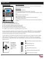
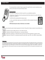
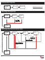
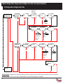
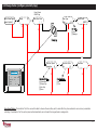
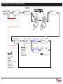
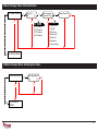
User Manual INTERNAL SIREN WARNING The Enforcer 32-WE control panel contains a 100 dBA siren, please be aware of this when in use. RINS1503-2 Software Revision >V9.26 Contents Page A: Introduction B: Keypads / Readers C: Using the Keyfob D: Arming the Enforcer E: Disarming the Enforcer F: Arming / disarming with the tag reader G: Open doors / Arm and Disarm (Entry Control) H: SMS Commands (GSM V9.2 or above only) H: SMS Commands (GSM version only) - Continued... I: Pyronix SMS Control Mobile Phone Application J: Chime Feature K: Personal Attack From Keypad L: Fire Alarm From Keypad M: Master Manager Menu Options N: Entering the Master Manager Menu 1 Master Manager Menu: Bypass Inputs 2 Master Manager Menu: Operate User Automation Outputs 3 Master Manager Menu: Configure Date & Time* 4 Master Manager Menu: Change Codes (Configure user codes, learn tags and keyfobs)* 5 Master Manager Menu: Review Logs (Event memory logs) 6 Master Manager Menu: SMS Phonebook 7 Master Manager Menu: Walk Test 8 Master Manager Menu: Bell Test 9 Master Manager Menu: PC Connect Menu 10 Master Manager Menu: Allow Engineer Menu 11 Master Manager Menu: Block Remote Arm 12 Master Manager Menu: Block UDL 13 Master Manager Menu: Exit Master Menu O: Engineer Contacts and Table P: Input Tables Q: User Tables R: Outputs S: Product Information T: Notes * To quick start the system, only these features are needed to be programmed. 2 3 4 5 6 7 8 8 9 10 12 13 13 13 14 15 15 15 16 17 20 21 21 21 22 22 23 23 24 25 26 28 29 30 31 A: Introduction Two Way Wireless High Security The Enforcer 32-WE is a wireless alarm system that has been designed with your security in mind; with quick and easy installation and minimal maintenance, the Enforcer 32-WE protects your home with a multitude of unique features. Taking full advantage of Pyronix’s innovative two way wireless technology, the wireless devices on the Enforcer 32-WE system are constantly communicating with each other, using the Pyronix High Security Wireless Encryption Protocol. The Enforcer 32-WE two way wireless devices are fully operational when the system is armed, making your system more secure, compared to other wireless systems, where devices are disabled for up to five minutes after every activation to save battery, therefore compromising your security. The Enforcer 32-WE has been engineered by Pyronix as a secure, reliable and easy to use wireless alarm system. It includes the following features: Battery Monitoring/Saving The Enforcer 32-WE system uses advanced technology to preserve the battery life of each wireless device. However, the Enforcer 32-WE informs you when a battery needs replacing a month in advance before the device stops working. This key feature gives you enough time to change the battery in the specific device. Other wireless alarm systems may not give you a low battery warning signal, meaning that devices could stop working, leaving your environment unprotected. High Security Encryption 128 bit high security wireless encryption protocol, and intelligent wireless jamming detection. User Friendly Keyfobs The fully two way wireless keyfob allows you to see the status of the control unit via 3 colour LEDs: System armed: When the system is armed a RED LED will illuminate momentarily System disarmed: When the system is disarmed a GREEN LED will illuminate momentarily System fault: When the system is in fault condition an AMBER LED will illuminate momentarily, This will also flash when the keyfob is unable to arm the system. It is possible to allocate different functions to each keyfob such as arming / disarming different areas, activating outputs to control external devices such as gates, requesting system status, and activating panic alarms. Up to 32 wireless keyfobs can be added to the Enforcer 32-WE system. Each wireless keyfob has its own user ID which can be reported to the ARC and user mobile phone which are stored into the event log of the control panel individually. The keyfob also allows you to arm/disarm every area individually, giving you total control of your system. User Automation Outputs The Enforcer 32-WE includes user automation outputs that give you the option to operate up to 20 devices such as gates, lights, sprinklers, etc. via your keypad or remotely via your Keyfob, extending the use of your security system. SMS Text Notifications and Remote Control The system will notify you via SMS text messages in real time. For example notification that your child has returned home from school safely or notification of a leakage of water in your property etc. 3 a = Quick exit manager menu. There are four different devices that may be used to arm/disarm the alarm system; these are the main keypad, the CHAP T external E R 2 : tag K Ereader, Y P Ainternal D S / tag R Ereader A D Eand R Sthe keyfob. b = Moves backwards to the previous menu B: Keypads / Readers There are four different devices that may be used to arm/disarm the alarm system; these are Master Code: 1234 the main Default keypad, external tag reader, internal tag reader and the keyfob. Control the Panel Keypad Arming/Disarming exit manager menu. Methods: a = Quick There are three different devices that may be used in the process of arming/disarming the alarm b = Moves backwards to the previous menu system; these are the keypad, tag reader and keyfob. item. Control Panel Keypad a = Quick exit manager menu. Button Operations c = Enables chime and displays additional b = Moves backwards to the previous menu/ Select area A. aindevices = Exit user menu information the log. There are four different that may be used to arm/disarm the alarm system; these are item. b = Moves backwards to the previous mainand menu / Selects area B. D = Moves forward in the log, scrolls between the main keypad, the external tagadditional reader, internal tag reader theitem keyfob. c = Enables chime displays cand = Displays additional in the log / Scrolls to previous option in a sub-menu / Selects options and enters the master managerinformation menu. information in thearea log. C. f p = Used to activate FIRe/PA alarms. D = Moves forward the log, scrolls between Din = Moves forward in the log / Selects area D. [ ] = Directional C Hbuttons. APTER 2: KEYPADS / READERS options andKeypad enters the master manager menu. Control Panel item. CHAPTER 2: KEY P A D=SEnables / R E A Dchime E R S and displays additional c information in the log. D = Moves forward in the log, scrolls betwee options andA Denters the master manager menu. f p = Used for Fire C Hand A PPA T Ealarms. R 2=: Quick K E Y Pexit S / R E Amenu. DERS manager a t =to Selects items enters menus. f p = Used activate FIRe/PA alarms. [] =and Directional buttons (used for choosing options and moving through text). There are four different devices that maydevices be used to= arm/disarm the these are f p = used Used tosystem; activate FIRe/PA alarms. There are four different that may be to alarm arm/disarm the alarm system; these are b Moves backwards to the previous menu t = Selects items and menus. x = Cancels items, and moves to theenters next [ ]the = Directional buttons. main keypad,the themain external tag reader, internal tag reader and the keyfob. keypad, the external tag reader, internal tag reader and the keyfob. . item. item in master menu x =manager Moves forward in the main menu and sub-menu / Exits option to sub-menu and sub-menu to t = Selects items and enters menus. main menu. [c ] = Directional buttons. How to navigate through the menu’s. = Enables chime and displays additional x = Cancels items, and moves to the next The Internal Tag Reader Control Panel Keypad Tag Area (Where you Control Panel Keypad x = “NO” - Press to move forward when the user mode manager menu. a = Quick exit . present information item in master manager menu ina the= Quick log. exit manager menu. your tag to arm/Unset) b = “BACK” - Press to move backward when in the user mode b = Moves backwards to the previous menu b = Moves to the previous menu D = Moves forward in backwards the log, scrolls between The Internal Tag Reader t= “YES” - Press to enter in a submenu or option when in the user mode item. item. Tag Area Ready (WhereLED you present options and chime enters the master manager menu. ] = Press to move from one option into another option while in a submenu c = Enables displays additional your tag to arm/Unset) c =and Enables chime and displays additional a = Press to quick exit the user menu from any main menu (written in capital letters) information in the log. Alarm LED f p = Used to activate FIRe/PA alarms. information in the log. c = “CANCEL” - Press to move back from one programmable option to the previous option. Ready LED D = Moves forward in the log, scrolls between t = Selects items and enters menus. Tamper LED x = Cancels items, and moves to the next D = Moves forward in the log, scrolls between [ ] =master Directional buttons. . item inand manager menu options enters the master manager menu. options and enters the master manager menu. Alarm Main menus are indicated with capital letters and endLED with a question mark (?), for example “CHANGE CODES?”. The sub-menus are indicated with fp = Used tof activate FIRe/PA alarms. Fault LED t = Selects items enters menus. p =and Used to activate FIRe/PA alarms. with small small letters and they also end with a question mark, for example “Learn codes/tags/keyfobs?”. Programmable options are indicated Tamper LED [ ] = Directional buttons. letters and do not finish with question mark (?) but Yes/No or other options are offered. [ ] = Directional buttons. Disarmed LED x = Cancels items, and moves to the next The Internal Tag Reader Fault LED t = Selects items and entersitems menus. = Selects and enters menus. . item in mastert manager menu Tag Area (Where you present your tag to arm/Unset) In order to navigate in the menu system one has to answer to the questions in thex main and sub menus. For to example, if the question is “CHANGE = Cancels items, moves theand next x =and Cancels items, moves to the next LED“Learn codes/tags/keyfobs?”. The External Tag Reader CODES”. Pressing t ‘YES’ will bring you in the Disarmed sub-menu Pressing t (YES) will take you. to the programmable item in master manager menu . item in master manager menu The Internal Reader options of this submenu. Pressing x ‘NO’ Tag will take you out of the individual option, will move you up from one sub-menu to the next sub-menu or Tag Area (Where you present The Internal TagThe Reader back to the main menu. Internal Tag Reader The External Tag Reader LEFT GREEN LED: Status indicator (extinguishes after a couple of seconds) LEFT GREEN LED: RED LED: This can be programmed by your After a valid tagLED: is Status LEFT GREEN indicator engineer to illuminate when the alarm has presented, the GREEN (extinguishes after a couple of seconds) activated for example. LED will illuminate RED LED: This can be programmed by your indicating the power engineer to illuminate when the alarm has status. activated for example. Tagyour Area (Where you present tag toTag arm/Unset) Area (Where you present Tagyour Area you tag present your tag to arm/disarm) tag(Where to arm/Unset) your to arm/Unset) Ready LED Ready LED to arm) Ready LED(Ready Ready LED Ready LED Alarm LED LEDAlarm LED Alarm Alarm LED (Shows alarms) Alarm LED Tamper LED Tamper LED Tamper LED Tamper LED (Shows tamper alarms) Fault LED Fault LED Tamper LED Disarmed LED Alert/Pending (Fault) LED (Shows system faults) Fault LED Disarmed LED Disarm LED (Shows Disarmed LEDsystem disarmed) 4 The External Tag Reader The External Tag Reader The External Tag Reader Fault LED ge: 8 make sure the exit door is closed properly C: Using the Keyfob Timed: Make sure you leave the building before the timer shown on the keypad expires to set: Press pushfunctions: to set The wireless keyfob has four buttons that maybePush programmed for the specific no action, show status, arm area, button installed by your engineer to disarm area, latch output, timed output and PA alarm activation. arm the system Locking the Keyfob SETTING USING A WIRELESS KEY-FOB All four buttons on the keyfob may be ‘locked’ to prevent from a user accidentally pressing them. Locking the keys on the keyfob is performed by buttons Press that are pressing To set viaany a key-fob. the diagonal key with one another at the same time (LOCK & II or UNLOCK & I). The key-fob LED will start to flash The RED LED will flash indicating that the fob hasGREEN been locked. indicating that the system is to setLED will flash indicating that the keyfob is To unlock, press both buttons together again andstarting the GREEN now unlocked. ‘Please wait arming wireless’ will be displayed on the keypad and the programmed area will begin to set. NOTE: When the keyfob is locked, all indications are also disabled. Buttons To ‘quick set’, press the key again. The buttons can be customised to operate as desired (programmed in the function ‘Change Codes’). Below are examples on how each button can be Once set, the key-fob LED will programmed: illuminate RED indicating that the BUTTON = Programmed for ‘Arm Area’ When pressed, one or more areas will beis armed system now set BUTTON = Programmed for ‘Disarm Area’. When pressed, one or more areas will disarmed. I BUTTON = Programmed for ‘User Output’. For example when pressed, a gate can be opened. When pressed again, a gate can be closed. II BUTTON = Programmed for ‘‘Status LED’. For example when pressed, the system status is shown’ RED = Armed, Page: 8GREEN = Disarmed, AMBER = Fault. Quick Arming If one of the buttons is programmed as ‘Arm Area’, the alarm system can be armed by the keyfob. The keypad will then start to count down the exit time (depending what the exit mode is programmed by the engineer). Once the alarm panel is in this ‘arming’ stage, it is possible to ‘quick arm’ the system by pressing the same button again; this will reduce the time of arming and therefore making the system arm immediately. The disarm LED on the keypad will turn off and a beep will be heard once the system has been armed and the RED LED on the keyfob will be illuminated for a short time. 5 D: Arming the Enforcer ] 9 2 0 [ t A a e r A s s e l e r i W g n i m r A t g n i m r A t i a W e s a e l P ] * * * * * * [ c 3 5 : 2 0 e m i T t ] D C B A s[ a e r A m r A e d o C r u o Y r e t n E E W 2 3 r e c r o f n E User Code User Code Deselect the Area's not needed to be armed ] * * * * * * ?[ g n i m r A p o t S ] D C B A ?[ g n i m r A p o t S CHAPTER 5: SETTING THE ALARM (CODE/TAG) 1 Enter your code and deselect any area’s that are not to be armed*. 2 Present your tag and deselect any area’s that are not to be armed*. 3 t Press the arming button on the keyfob**. *This will only be possible if “Arm Area Choice” is selected as ‘Yes’ in the function “Learn User Codes/Tags/Keyfobs. If selected as “No” then all areas allocated to the user code will arm. **The keyfob buttons can be programmed in the function “Learn User Codes/Tags/Keyfobs”. 6 E: Disarming the Enforcer E W 2 3 r e c r o f n E c t 3 5 : 2 0 e m i T ] * * * * * * [ A a e r A m r A t ] D C sB aA e[ r A m r a s i D e d o C r u o Y r e t n E E W 2 3 r e c r o f n E User Code Deselect the Area's to be disarmed CHAPTER 5: SETTING THE ALARM (CODE/TAG) 1 Enter your code and deselect any area’s that are not to be disarmed*. 2 Enter your code and deselect any area’s that are not to be disarmed*. 3 Press the arming button on the keyfob**. *This will only be possible if “Arm Area Choice” is selected as ‘Yes’ in the function “Learn User Codes/Tags/Keyfobs. If selected as “No” then all areas allocated to the user code will disarm. **The keyfob buttons can be programmed in the function “Learn User Codes/Tags/Keyfobs”. 7 F: Arming / disarming with the tag reader If you have a tag reader installed, then it will be possible to arm and disarm the alarm system using a tag. Disarmed Disarmed Armed Armed NOTE: If the Enforcer has failed to set, a fault will be displayed on the internal tag reader or a fail to set sound will activate on the external tag reader buzzer. G: Open doors / Arm and Disarm (Entry Control) A tag reader can also be used to unlock entry doors. Disarmed Disarmed Locked Armed Locked Armed NOTE: If the Enforcer has failed to set, a fault will be displayed on the internal tag reader or a fail to set sound will activate on the external tag reader buzzer. External Tag Reader Instructions: Arming: Present a valid tag to the reader, the GREEN LED will illuminate on the external reader, remove the tag, the door will unlock, then present the same tag within 10 seconds and the system will arm and the door will lock. Disarming: Present a valid tag to the reader and then remove it, the status will be shown (the alarm symbol will illuminate indicating the system is armed on the internal reader and the RED LED on the external reader), present the same tag wihthin 10 seconds again and the system will be disarmed, and the door will unlock. Access Control/Entry Control: The readers can be used also for opening doors only without the ability to arm and disarm. Please contact your installer for more information on this feature. 8 H: SMS Commands (GSM V9.2 or above only) If you have purchased the GSM version of Enforcer, it will allow you to send SMS commands via a mobile phone to be able to arm/disarm the panel remotely and others. See below the different SMS commands available. NOTE: Any text message command to the Enforcer will need to start with a valid user code. NOTE: Text messages commands are not case sensitive except when the used outputs are activated. NOTE: If a text messages commands is not recognised by Enforcer it will send back to the user the wrong command. Arming via SMS text command Example SMS command send: Description: Example SMS command response: 123456 Arm A 123456 = User Code. Arm A = Will arm the Enforcer in Area A. Final Arm; Area A 123456 Arm ABCD 123456 = User Code. Arm ABCD = Will arm the Enforcer in Area ABCD. Final Arm; Area ABCD NOTE: If no areas are specified then all areas will arm (default). In ‘One Area’ Mode, the default will be Area A. Disarming via SMS text command Example SMS command send: Description: Example SMS command response: 123456 Disarm A 123456 = User Code. Disarm A = Will disarm Area A. Disarm; Area A 123456 Disarm ABCD 123456 = User Code. Disarm ABCD = Will disarm the Area ABCD. Disarm; Area ABCD NOTE: If no areas are specified then all areas will disarm (default). In ‘One Area’ mode, the default will be Area A. Arming with inputs bypassed via SMS text command Example SMS command send: Description: Example SMS command response: 123456 Arm A Bypass 4 123456 = User Code. Arm A Bypass 4 = Arms Area A and will bypass input number 4. Input Bypass; Area A Input 04 Force Arm: Area A 123456 Arm A Bypass Kitchen 123456 = User Code. Arm A Bypass Kitchen = Arms Area A and will bypass Input Bypass; Area A Kitchen the input that is called Kitchen. Force Arm: Area A Bypassing inputs via SMS text command Example SMS command send: Description: Example SMS command response: 123456 Bypass 6 123456 = User Code. Bypass 6 = In the next arming procedure, input number 6 will be bypassed. Input Bypass; Area A Input 06 123456 Bypass Garage 123456 = User Code. Bypass Garage = In the next arming procedure, the input called Garage will be bypassed. Input Bypass; Area A Garage NOTE: The name of the output has to be one word and spelled exactly as written in the panel. For example, Garage Door is not acceptable. It has to be written as Garage-Door in the panel and the respective command will be Garage-Door. 9 H: SMS Commands (GSM version only) - Continued... Checking the System Status via SMS text command Example SMS command send: Description: Example SMS command response: 123456 Status 123456 = User Code. Status Area A Disarmed No Faults Area B Disarmed No Faults Area C Disarmed No Faults Area D Disarmed No Faults Operating the User Automation Outputs via SMS text commands Example SMS command send: Description: Example SMS command response: 123456 Output 1 On 123456 = User Code. User Output 1 turns on. OUTPUT 1 ON 123456 Output Garage-Door On 123456 = User Code output Garage-Door on = Turns output named as Garage-Door on. OUTPUT Garage-Door ON 123456 Output Garage-Door Off 123456 = User Code output Garage-Door off = Turns output named as Garage-Door off. OUTPUT Garage-Door OFF NOTE: The user automation outputs can be also activated via the keypad or the keyfob. NOTE: The name of the output has to be one word and spelled exactly as written in the panel. For example, Garage Door is not acceptable. It has to be written as Garage-Door in the panel and the respective command will be Garage-Door. Checking the User Automation Outputs status via SMS text commands Example SMS command send: Description: Example SMS command response: 123456 Output 1 Status 123456 = User Code. User Output 1 status check. OUTPUT ON or OUPUT OFF 123456 Output Garage-Door Status 123456 = User Code. Output Garage-Door status check. OUTPUT Garage-Door ON or OUTPUT Garage-Door OFF NOTE: The name of the output has to be one word and spelled exactly as written in the panel. For example, Garage Door is not acceptable. It has to be written as Garage-Door in the panel and the respective command will be Garage-Door. Changing a Mobile Number via SMS text commands Example SMS command send: Description: Example SMS command response: 123456 Change 07777888999 07878888999 123456 = User Code. Change number 07777888999 to number 07878888999 CHANGE 07878888999 Start Uploading/Downloading via SMS text command Example SMS command send: Description: Example SMS command response: 123456 UDL 123456 = User Code. UDL = The Enforcer will make an outgoing data connection to the programmed PC1 number. No response as the panel is already connected to the PC1 9999 UDL 9999= Engineer Code UDL = The Enforcer will make an outgoing data connection to the programmed PC1 number. NO Response as the panel is already connected to the PC1 10 I: Pyronix SMS Control Mobile Phone Application There is a mobile phone application (Android only) that is available to download via our website and will control certain aspects of your control panel from your mobile phone. 1) Download the Pyronix SMS control application from http://www.pyronix.com/pyronix-downloads.php 2) Install the application on your mobile phone (making sure “download from unknown sources” is enabled in your security settings). 3) Open the application, it will then be installed on your phone automatically. 4) The icon to the left will be displayed on your phone menu. Press the icon. 5) Once the start up screen has loaded, you will see three icons: Arm Area A, Disarm Area A and Panel Status. These are the default operations. 6) Press ‘Settings’ and enter all your panel information such as panel name, (your engineer will know what this is), panel input names (if you wish to enter your zone names on here). You can also choose the application language and a password for security. NOTE: It is recommended that a password is entered so only you will have access to arming/disarming your control panel etc. 7) Press ‘Command’ to choose different operations to the PCX control panel that you wish to operate. Press ‘Add Command’ - at default “Arm” will be selected, press the drop down box to view all other operations that are possible: Arming, disarming, arm with bypass, bypass zones, control user output, output status and system status. You may also choose your own icon style as well so the different commands can be easily identified. Once all changes have been made press ‘SAVE’ and click back. 8) All icons and commands will the be displayed on your home screen which can then be pressed and operated. Screenshots 11 2 Omitting Inputs J: Chime Feature K: Personal Attack From Keypad The chime feature can be used on door contacts to enable a ‘chime’ sound when a door (input) is opened. This feature can be set up by your installer. If an PA alarm is needed, press and hold both the 1 and 7 keys or hold p for 3 seconds and a ‘PA’ alarm will be generated. To disable the chime on the keypad, close all doors and when ‘c’ is displayed, press the c key, a capital ‘C’ will be displayed, this will then activate the chime on any additional keypads with extension speakers installed. If you wish to disable the chime altogether press the c key again. Note: The PA facility needs to be enabled by your engineer (either silent or full alarm) L: Fire Alarm From Keypad If a fire alarm is needed, press and hold f for 3 seconds and a ‘fire’ alarm will be generated. Note: The Fire alarm key need to be enabled by your engineer. Please note that the key-fob can also be programmed to support a PA alarm. Please discuss this with your engineer. NOTE: Chime should not be used on motion detectors as this will drain the battery. 3 Keypad Hold Up VA N Cemergency E D F U alarm N C T isI Oneeded, N S press If an and hold both the 1 and 7 keys. A ‘hold up’ alarm will be generated. CHAPTER 12: ADVANC 12.1 Chime Feature Note: The Hold Up facility needs to be enabled by your engineer (either silent or full alarm) 2-Key HU and any duress codes programmed on the system by your engineer are not permitted to send a signal to the Alarm Receiving Centre under police regulations in England, Wales or Northern Ireland Please note that the key-fob can also be programmed to support a hold up alarm. 12 Please discuss this with your engineer. 12.2 Omitting Inputs M: Master Manager Menu Options Bypass Inputs Disables any sensor (input) on the system for the current arming period. This feature also disables tamper alarms. Operate User Outputs Activates/deactivates user automation outputs that are used to activate remotely the devices such as electronic gates, lights etc. *Date & Time Programmes the date and time and enables the summertime automatic adjustment. *Learn User Codes, Keyfobs and Tags Programmes the user codes, tags and learns keyfobs to the Enforcer 32-WE. Review Log The ‘Review Logs’ function is used to view all operational information of the alarm system, such as arming/disarming information, access control and alarm activations etc. SMS Phonebook If SMS texting is enabled, there will be up to 4 mobile numbers that can be programmed to send SMS alarms. Please discuss this feature with your installer if required. Walk Test The ‘Walk Test’ function allows the testing of all programmed inputs on the alarm system. Bell Test This function is used to tests the external siren (wired and wireless) and strobe. PC Connect Menu The control panel may be dialled into, and programming information kept on a PC using the InSite UDL software. This function allows the control panel to dial a Pre-programmed PC telephone number (programmed by your engineer). This is usually used by your engineer during a maintenance call. Allow Engineer Menu If this function is enabled, the engineer will require authorisation from you before they can access the engineer menu. Block Remote Arming Blocks any attempt at arming the system remotely via the upload/download software Block UDL Blocks any attempt at dialling into the system remotely via the upload/download software Exit Manager Mode Exits the Manager Mode NOTE 1: Pressing the A key will exit the master manager menu at any main menu option above. NOTE 2: Make sure you change the default master user code. *These features are needed to quickly set up the Enforcer. 13 N: Entering the Master Manager Menu ? S T U P N I S S A P Y B ] * * * * [ ] [ t u p n I s s a p y B ] [ t u p n I s s a p y B ? S T U P N I S S A P Y B 1 0 t u p n I : t u p n I n a e s o o h C 6 6 o t 1 0 R E S U E T A R E P O ? S T U P T U O n O t u p t u O f f O t u p t u O t u p t u O t c e l e S R E S U E T A R E P O ] 1 0 [ ? S T U P T U O x f f O / n O t u p u O n r u T s u t a t S t u p u O t n e r r u C w o h S : t u p t u O n o i t a m o t u A r e s U t c e l e S 0 1 3 t t u u p p t t u u O O ] ] 1 0 0-[ 3 [ ? E M I T & E T A D 14 c 3 5 : 2 0 e m i T b t t t t x x x x x x e d o C r u o Y r e t n E E W 2 3 r e c r o f n E b t t t1234 Default Master User Code: D 1 Master Manager Menu: Bypass Inputs 2 Master Manager Menu: Operate User Automation Outputs 3 Master Manager Menu: Configure Date & Time* ] 1 9 3 5 [ 0 s e t u n i M 3 2 0 s r u o H 1 3 1 y a D ] 3 2 [ ] 1 0 [ ] 1 0 2[ 1 1 h t n o M 9 9 0 0 r a e Y ? E M I T & E T A D ] 7 0 [ ? j d A e m i T r e m m u S ] 0 [ t o N : s n o i t p O x x x x ) ( ) ( ) ( ) ( ) ( x x x t t t t t t o N ] 0 [ s e Y ] 1 [ ? S E D O C E G N A H C b 15 4 Master Manager Menu: Change Codes (Configure user codes, learn tags and keyfobs)* 4.1 Change Codes: Configure User Codes o t y e K C s s e r P e d o c E T E L E D ] D C B aA e[ r A n I r e s U e p y T r e s U ] 0 [ r e s U e] d o C[ r e s U r e t n E ] 1 0 [ y t p m E ? s b o f y e K n r a e L ? S G A T & S B O F Y E K : e p y T r e s U r e s U ] 0 [ r e g a n a M ] 1 [ e m a N r e s U ] 0 e [ c i o h C m r A a e o r N A s n o i t p O m r A r e s U ] 0 [ m r A / m r a s i D : e c i o h C m r A a e r A : s n o i t p O m r A r e s U o N ] 0 [ m r A / m r a s i D ] 0 [ s e Y ] 1 [ y l n O m r a s i D ] 1 [ y l n O m r A ] 2 [ e n o N ] 3 [ ] 0 e [ c i o h C m r A a e o r N A s n o i t p O m r A r e s U ] 0 [ m r A / m r a s i D ] D C B a A e [ r A n I r e s U r e g a n a M r e t s a M r e t s a M e g n a h C ] * * * * * * [ e d o C ? e d o C r e g a n a M : e c i o h C m r A a e r A : s n o i t p O m r A r e s U o N ] 0 [ m r A / m r a s i D ] 0 [ s e Y ] 1 [ y l n O m r a s i D ] 1 [ y l n O m r A ] 2 [ e n o N ] 3 [ e m a N r e s U ? G O L W E I V E R 16 x x x x x t _ t t t t t x x x t t _ t x b / s g a T / s e d o C r e s U S E D O C R E S U N R A E L x x x x x x t t t t t t Arm Area Choice: If selected as ‘Yes’ the user will be able to choose the area they wish to arm after they have entered a user code or presented a valid tag. If selected as ‘No’ the control panel will automatically arm all area’s the keypad/code is assigned to. 4.2 Change Codes (configure proximity tags) o t y e K C s s e r P g a t E T E L E D ] 0 [ r e s U t : e p y T r e s U x ] D C B aA e[ r A n I r e s U e p y T r e s U ? s b o f y e K n r a e L t e] d o C[ r e s U r e t n E ] 1 0 [ y t p m E / s g a T / s e d o C r e s U t x r e s U ] 0 [ x r e g a n a M ] 1 [ x g a t t n e s e r P t ] 0 [ o N ] 0 [ m r A / m r a s i D Enforcer Time 11:00am c x x e m a N r e s U e c i o h C m r A a e r A s n o i t p O m r A r e s U t t _ t x : s n o i t p O m r A r e s U : e c i o h C m r A a e r A m r A / m r a s i D ] 0 [ o N ] 0 [ y l n O m r a s i D ] 1 [ s e Y ] 1 [ y l n O m r A ] 2 [ e n o N ] 3 [ Arm Area Choice: If selected as ‘Yes’ the user will be able to choose the area they wish to arm after they have entered a user code or presented a valid tag. If selected as ‘No’ the control panel will automatically arm all area’s the keypad/code is assigned to. 17 4.3 Change Codes (learn/configure keyfobs) o t y e K C s s e r P n o t t u b Y N A d l o H d n a s s e r P h s a l f s D E L l i t n u s d n o c e s 5 r o f e m a N r e s U e d o c E T E L E D e] d o C r[ e s U r e t n E ] 1 0 [ y t p m E / s g a T / s e d o C r e s U ? s b o f y e K n r a e L ] a e r A m r A f I s u t a t S w o h S a e r A m r a s i D r o A a [ e r A n I r e s U ] 1 [ n o i t c A n o t t u B n o t t u B t c e l e S ] 1 [ n o t t u B : n o i t c A n o t t u B ] 1 0 [ t u p t u O t u p t u O e t a r e p O f I n o i t c A o N ] 0 [ s u t a t S w o h S ] 1 [ 0 3 1 d e n i f e D r e s U ] 9 9 1 0 7 1 [ K C O L N U n o t t u B ] 2 [ t u p t u O e t a r e p O ] 4 [ K C O L n o t t u B ] 1 [ a e r A m r a s i D ] 3 [ t u p t u O a e r A m r A ] 2 [ : n o t t u B t c e l e S I n o t t u B ] 3 [ I I n o t t u B ] 4 [ K C O L N U + K C O L s n o t t u B ] 5 [ I I + I s n o t t u B ] 6 [ I + K C O L s n o t t u B ] 7 [ I I + K C O L N U s n o t t u B ] 8 [ 18 t _ t t x t x 5 Master Manager Menu: Review Logs (Event memory logs) s t n e v E d e c n e l i S m r a l A t 1 0 r e s U : t n e v e e h t n o n o i t a m r o f n i e r o m n i a t b o o T s s e r P g o L f o t r a t S l l a r o f t a e p e R 4 4 : 1 1 : 0 0 1 0 / 1 0 ? g o L l r t C / s s e c c A s t n e v E t r o o D n e p o r e s U t g o L f o t r a t S l l a r o f t a e p e R 4 4 : 1 1 : 0 0 1 0 / 1 0 ? g o L l e n a P ? G O L W E I V E R x x c x x x c x x t t t t c 1 0 r e s U t : t n e v e e h t n o n o i t a m r o f n i e r o m n i a t b o o T s s e r P c ? K O O B E N O H P S M S b 19 6 Master Manager Menu: SMS Phonebook e s u t o n o D ] 1 0 [ x x e l i b o M r e s U r e b m u N S M S ? K O O B E N O H P S M S t t SMS Number [00]-[25] t x ? T S E T K L A W NOTE: Number 1 is normally reserved for ARC communications. Numbers 2-25 is normally reserved for SMS messaging. b Before you change this function, please consult your installer. 7 Master Manager Menu: Walk Test s t u p n I t s e T k l a W s a e r A t s e T k l a W ? T S E T K L A W 1 0 t u p n I ] D C B A [ t t x x ] 1 0 t[ u p n I t s e T k l a W x t ? T S E T L L E B b 8 Master Manager Menu: Bell Test . . . l l e B g n i t s e T ? T S E T L L E B t x ? U N E M T C E N N O C C P b 20 t x t 9 Master Manager Menu: PC Connect Menu C P e t o m e R g n i l l a C n o i t a r e p O t c e l e S ] 0 [ C P o t t c e n n o C ] 1 [ o t C P t c el l a e Si d ? U N E M T C E N N O C C P : n o i t a r e p O t c e l e S : l a i D o t C P t c e l e S 1 m e d o M C P ] 1 [ C P o t t c e n n o C ] 0 [ 2 m e d o M C P ] 2 [ l a i D t s e T ] 1 [ 3 m e d o M C P ] 3 [ e c i v r e S M R ] 2 [ 4 m e d o M C P ] 4 [ C P m o r f a t a D ] 3 [ C P o t a t a D ] 4 [ s c i t s o n g a i D ] 5 [ g n i n o i s s i m m o C ] 6 [ ? U N E M R G N E W O L L A ? u n e M r g n E w o l l A ? U N E M R G N E W O L L A ] 1 [ s e Y E T O M E R K C O L B ? G N I M R A b x x t t x x x x t t t t b 10 Master Manager Menu: Allow Engineer Menu 21 11 Master Manager Menu: Block Remote Arm ? m r A e t o m e R k c o l B E T O M E R K C O L B x ] 0 [ o N ? G N I M R A t t This function will block any attempt made to arm and disarm the UDL software if enabled. x : m r A e t o m e R k c o l B o N ] 0 [ s e Y ] 1 [ ? L D U K C O L B b 12 Master Manager Menu: Block UDL R E G A N A M T I X E 22 ? E D O M b x ] 0 [ x ? L D U k c oo l N B ? L D U K C O L B t t Block UDL: [0] No [1] Yes This function will block any attempt made to dial into the control panel to upload and download information if enabled. 13 Master Manager Menu: Exit Master Menu E W 2 3 r e c r o f n E ? S T U P N I S S A P Y B c 5 2 : 0 e m i T c 5 2 : 0 e m i T ? E D O M r e g a n a M t i x e o t y e k A e h t s s e r P R O m e t i u n e m n i a m y n a m o r f e d o m s r e t t e l l a t i p a c n i d e y a l p s i d ) ( BYPASS INPUTS? b E W 2 3 r e c r o f n E R E G A N A M T I X E x a t 23 O: Engineer Contacts and Table Alarm Company Date of Installation Site Reference Engineer Name Engineer Contact Number Installed to Grade 2? Yes / No Environmental Class II Other Comments 24 P: Input Tables Wireless Inputs Input Name Input Areas Description 1 2 3 4 5 6 7 8 9 10 11 12 13 14 15 16 17 18 19 20 21 22 23 24 25 26 27 28 29 30 31 32 25 P: Input Tables Wired Inputs 33 (RIX2) 34 (RIX2) 35 (RIX Address 0) 36 (RIX Address 0) 37 (RIX Address 0) 38 (RIX Address 0) 39 (RIX Address 0) 40 (RIX Address 0) 41 (RIX Address 0) 42 (RIX Address 0) 43 (RIX Address 1) 44 (RIX Address 1) 45 (RIX Address 1) 46 (RIX Address 1) 47 (RIX Address 1) 48 (RIX Address 1) 49 (RIX Address 1) 50 (RIX Address 1) 51 (RIX Address 2) 52 (RIX Address 2) 53 (RIX Address 2) 54 (RIX Address 2) 55 (RIX Address 2) 56 (RIX Address 2) 57 (RIX Address 2) 58 (RIX Address 2) 59 (RIX Address 3) 60 (RIX Address 3) 61 (RIX Address 3) 62 (RIX Address 3) 63 (RIX Address 3) 64 (RIX Address 3) 65 (RIX Address 3) 66 (RIX Address 3) 26 Input Name Input Areas Description Q: User Tables User Name Code/Tag/Keyfob User Name Code/Tag/Keyfob User 1 33 65 2 34 66 3 35 67 4 36 68 5 37 69 6 38 70 7 39 71 8 40 72 9 41 73 10 42 74 11 43 75 12 44 13 45 14 46 15 47 16 48 17 49 18 50 19 51 20 52 21 53 22 54 23 55 24 56 25 57 26 58 27 59 28 60 29 61 30 62 31 63 32 64 Name Code/Tag/Keyfob 27 R: Outputs Wired Outputs Latched / Timed Type Action Latched / Timed Type Action PGM1 (Onboard) STRB (Onboard) BELL (Onboard) PGM1 (ROX) PGM2 (ROX) PGM3 (ROX) PGM4 (ROX) PGM5 (ROX) PGM6 (ROX) PGM7 (ROX) PGM8 (ROX) PGM9 (ROX) PGM10 (ROX) PGM11 (ROX) PGM12 (ROX) PGM13 (ROX) PGM14 (ROX) PGM15 (ROX) PGM16 (ROX) Wireless Outputs BELL 1 STRB 1 BELL 2 STRB 2 28 S: Product Information For electrical products sold within the European Community. At the end of the electrical products useful life, it should not be disposed of with household waste. Please recycle where facilities exist. Check with your Local Authority or retailer for recycling advice in your country. When disposing of the product and accessories, the batteries must be removed and disposed of separately in accordance with the local regulations. 29 T: Notes 30 T: Notes 31 2 EN50131-1:2006+A1:2009 EN50131-3:2009 EN50131-1 EN50131-6:2008 PD6662:2004 Security Grade 2 EN50131-5-3:2005+A1:2008 Environmental Class 2 Security Grade 2 Environmental Class II 3 Secure Holdings Pyronix House Braithwell Way Hellaby Rotherham S66 8QY Website: www.pyronix.com