1
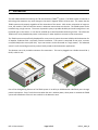
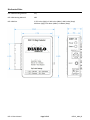
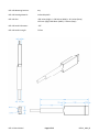
User Manual
DSP-13
Tri-Axis Detection (TRIADTM) System
Diablo Controls, Inc.
Copyright © 2014
Document:
DSP13_MAN_B
Released:
October 8, 2014
Pros Who Know Trust Diablo
1.
Contents
2.
Introduction ........................................................................................................................................................ 3
3.
Technical Data .................................................................................................................................................... 4
Functional Data....................................................................................................................................................... 4
Electrical Data ......................................................................................................................................................... 4
Environmental Data ................................................................................................................................................ 4
Mechanical Data ..................................................................................................................................................... 5
4.
Features and Functions ...................................................................................................................................... 7
Presence Detection................................................................................................................................................. 7
Pulse Detection....................................................................................................................................................... 7
Sensitivity................................................................................................................................................................ 7
Fail-Safe vs Fail-Secure ........................................................................................................................................... 7
Fail-Safe .................................................................................................................................................................. 7
Fail-Secure .............................................................................................................................................................. 8
Detector Reset ........................................................................................................................................................ 8
Indicators ................................................................................................................................................................ 8
5.
Installation ........................................................................................................................................................ 10
Detector Installation ............................................................................................................................................. 10
Sensor Installation ................................................................................................................................................ 10
6.
Configuration .................................................................................................................................................... 12
Sensitivity.............................................................................................................................................................. 12
DIP Switches ......................................................................................................................................................... 12
Pin Out .................................................................................................................................................................. 13
7.
Troubleshooting ............................................................................................................................................... 14
No Power LED ....................................................................................................................................................... 14
Power LED Slowly Flashing ................................................................................................................................... 14
Power LED Shows Two Quick Flashes Once Every Two Seconds.......................................................................... 14
Detect LED Flashes Quickly (5 Hz) ........................................................................................................................ 14
Detect LED Intermittently Comes On / Stays On Without a Vehicle Present....................................................... 15
Detect LED Will Not Come On With a Vehicle Present......................................................................................... 15
DSP-13 User Manual
Page 2 of 15
DSP13_MAN_B
2.
Introduction
The DSP-13M and DSP-13S make up the TRI-Axis Detection (TRIADTM) system. The TRIAD system is based on a
technology that measures very small changes in the earth’s magnetic field in all three axes. This means that the
TRIAD system works properly regardless of the orientation of the sensor. With sensor orientation no longer an
issue, the installer is able to install the sensor in whatever manner best suits the site. The TRIAD system can be
installed using a single saw cut. The sensor is potted in epoxy to provide durability and small enough that it can
be placed right in the saw cut. It can also be installed up to three feet below the driving surface. This allows the
TRAID sensor to be placed below pavers in a driveway or under asphalt or concrete in new construction.
The TRIAD system was specifically developed for access control systems that need reliable vehicle detection for
all weather conditions with a minimally invasive installation. The system is comprised of two parts, a master
unit (DSP-13M) and a sensor (DSP-13S). Up to two sensors can be connected to a single master. The advanced
sensor’s small size and high sensitivity make it ideally suited to vehicle detection applications.
The detector uses a 10-pin Molex connector for connections. This can be plugged into a Diablo Controls RK-1,
RK-50, or RK-51 rack.
One of the distinguishing features of the TRIAD system is its ability to hold detection indefinitely even through
power interruptions. Even if a vehicle arrives when the unit is without power, when power is restored the TRIAD
system will show detect if there is now a vehicle in the detection zone.
DSP-13 User Manual
Page 3 of 15
DSP13_MAN_B
3.
Technical Data
Functional Data
Sensitivity:
Ten sensitivities selectable for presence or pulse modes of operation. Level 5
should be sufficient for most applications.
Pulse Output:
250 milliseconds
Response Time:
Activation Deactivation -
Vehicle Hold Time:
Indefinite, depending on environmental noise conditions.
15 milliseconds minimum. 55 milliseconds maximum.
15 milliseconds minimum. 135 milliseconds maximum.
Electrical Data
DSP-13M Operating Voltage:
8 volts to 30 volts DC
DSP-13M Operating Current:
60 milliamps maximum and includes all current used by the sensors.
DSP-13M Output Rating:
The output is an open-collector output rated for sinking up to 50 milliamps. It is
not an isolated output and is referenced to pin 10 (Common) of the DSP-13M.
Maximum Number of Sensors: A DSP-13M (Master) can support up to two DSP-13S (Sensors) connected in
series.
Sensor to Sensor Proximity:
The sensors are passive measurement devices and as such will not interfere
with other sensors at any distance.
Environmental Data
Operating Temperature:
-35°F to 165°F (-37°C to 74°C)
Storage Temperature:
-40°F to 176°F (-40°C to 80°C)
Humidity:
Up to 95% relative humidity non-condensing
DSP-13 User Manual
Page 4 of 15
DSP13_MAN_B
Mechanical Data
DSP-13M Mounting Position:
Any
DSP-13M Housing Material:
ABS
DSP-13M Size:
2.375 inches (High) x 2.340 inches (Wide) x .860 inches (Deep)
60.36mm (High) x 59.44mm (Wide) x 21.84mm (Deep)
DSP-13 User Manual
Page 5 of 15
DSP13_MAN_B
DSP-13S Mounting Position:
Any
DSP-13S Housing Material:
Yellow Polyolefin
DSP-13S Size:
.650 inches (High) x 3 .500 inches (Wide) x .312 inches (Deep)
16.51mm (High) x 88.90mm (Wide) x 7.92mm (Deep)
DSP-13S Lead-in Diameter:
.175”
DSP-13S Lead-in Length:
75 feet
DSP-13 User Manual
Page 6 of 15
DSP13_MAN_B
4.
Features and Functions
Presence Detection
The output will remain activated as long as a vehicle is sensed in the detection zone. This detector always
operates in a permanent presence or infinite presence detection mode. The sensor technology used is capable
of remembering vehicles in the detection zone even if the power is interrupted for long periods of time. In fact,
it can determine if a vehicle arrived in the detection zone while power was removed and provide the correct
presence output on power restoration.
Pulse Detection
The pulse mode used is commonly referred to as Pulse On Entry.
When pulse mode is selected the channel will output a pulse when the vehicle is first detected and will not
output again until the detection zone is no longer occupied.
Sensitivity
The detector has ten user selectable sensitivity levels. In most situations the setting of 5 will work effectively.
The sensor does have hysteresis between the detect and drop thresholds to ensure that the detector output
does not chatter during fringe detections.
Fail-Safe vs Fail-Secure
Here’s a little note on fail-safe versus fail-secure operation. In general, a fail-safe detector will output “detect”
when the sensor circuit is failed. This is always useful on a safety sensor to prevent accidental closure of a gate
arm on a vehicle. On the free exit sensor this will keep the gate open until the situation is fixed. This is useful in
applications where it is important to allow traffic flow to continue. A fail-secure detector will never output
“detect” when the sensor circuit is failed. This will keep the gate closed. This is useful in high-security areas or
installations where containment is needed.
Fail-Safe
When the detector is in the presence mode of operation and a sensor failure is detected, the output will stay
activated during the failure. In gate applications this feature is used to automatically open the gate if a sensor
fails.
It should be noted that a power failure will always result in a fail-secure operation. Fail-safe operation is only
available when a valid input voltage is applied to the detector. When configured for pulse output, the detector
will always operate in the fail-secure mode.
DSP-13 User Manual
Page 7 of 15
DSP13_MAN_B
Fail-Secure
When the detector is in the presence mode of operation and a sensor failure is detected, the output will stay
deactivated during the failure. In gate applications this feature is used to keep the gate closed if a sensor fails.
It should be noted that a power failure will always result in a fail-secure operation. When configured for pulse
output the detector will always operate in the fail-secure mode.
Detector Reset
When the reset switch is pressed, the master will send a reset command to all connected sensors. If a prior
sensor fault was being displayed, it will be cleared. Care should be taken to insure that the detector is not reset
while any vehicles or objects are in or near the detection zone. These vehicles or objects may cause a
permanent offset in the reference readings for the sensors and may impact correct operations of the sensors.
Indicators
The DSP-13M is equipped with two LED indicators: Power (Green) and Detect (Red).
Power LED – The green power LED has four possible states:
OFF
The voltage applied to the detector is less than the minimum display
voltage of approximately 3.3 volts. The detector should not be
operated below 7 volts DC as unpredictable operation will occur.
RESET
When the detector is reset (a reset occurs automatically at power up),
the LED will turn off for 200 milliseconds, on for 200 milliseconds, off for
200 milliseconds, and then resume its normal display.
PRIOR FAILURE
The detector is equipped with the ability to remember prior faults that
have occurred since the last power interruption or reset. The LED will
turn off for 100 milliseconds, on for 100 milliseconds, off for 100
milliseconds, on for 1700 milliseconds and then repeat the sequence
until power is cycled or the is detector reset.
NORMAL
The LED is always on when the detector is in its normal state of
operation with no prior failure in memory.
DSP-13 User Manual
Page 8 of 15
DSP13_MAN_B
Detect LED – The red Detect LED is used to display the status of detection zone and a pending change of
sensitivity. There are several different statuses that can be displayed on this LED:
RESET
When the detector is reset (a reset occurs automatically at power up),
the LED will turn off for 200 milliseconds, on for 200 milliseconds, off for
200 milliseconds, and then resume its normal display.
SENSITIVITY CHANGE
When the sensitivity setting is changed, the detect LED will begin
flashing at a 5 Hz rate (100 milliseconds on, 100 milliseconds off). This
indicates that the reset switch must be pressed to send the new
sensitivity setting to the sensor and stop the flashing. Returning the
sensitivity to the original setting will also stop the flashing.
DETECTION
When the detector is in presence mode the LED will be on while a
vehicle is in the detection zone. In the pulse mode the LED will turn on
for 250 milliseconds with the output, off for 250 milliseconds, and then
show the occupancy display until the vehicle exits.
OCCUPANCY
When the detector is operating in the pulse mode of operation and the
detection zone is currently is occupied, the LED will be turned on to a
dimmer level than normal and the LED will be flashed at a very fast rate
that will make it look like it is flickering.
This display is meant to be easily distinguishable from the normal on
display. With this additional display mode, the pulse mode of operation
can easily be monitored for correct operation.
A look at the following figure will show how this occupancy indication is
used to provide additional information during pulse mode operation. In
the figure the occupancy display is shown as the gray shaded area.
DSP-13 User Manual
Page 9 of 15
DSP13_MAN_B
5.
Installation
Detector Installation
Location: The detector should be installed in a weatherproof location that is near the detection zone. Ideally, a
technician should be able to see the detection zone and the detector at the same time.
Mounting: The detector will function when mounted in any orientation. When using a rack, it is best to mount
the rack such that the front panel of the detector will be easily accessible for configuration and troubleshooting.
Wiring: When the detector is plugged in to a rack, the rack will provide and identify the wiring connection
points.
Sensor Installation
The reliability and overall performance of the detector are greatly dependent on the installation of the sensor
itself. There are three factors that go into a good sensor installation: sensor location, type of wire used (if
additional lead-in is needed), and installation practices.
Sensor Location: The sensors sense changes in the earth’s magnetic field. The length of the edge facing the
sensor will affect its detection distance. As a vehicle approaches a sensor head on, it presents an edge
approximately 6 (six) foot long. However, if the vehicle drives by the side of the sensor, it presents an edge of
typically 12 to 15 feet. Therefore, the sides of a vehicle are easier to detect than the vehicle head on. This
causes the detection pattern to be oblong in the driving lane. Usually 25% to 50% wider than it is long.
If the travel lane if wider than 15 feet, it may be advisable to use two sensors with the one master. The second
sensor can be placed without concern for proximity to the other sensor. The sensors will not interfere with each
other in any way. When two sensors are used, they must be connected in series to the master, not connected in
parallel.
It is advised that you tape down the sensor on the surface in the approximate location that you plan to install at.
Connect it to the master and verify that detection zone is where you want it to be and that moving objects, such
as a gate, are not picked up by the sensor. You may need to adjust the sensitivity and the placement of the
sensor to get the desired detection zone. Be careful to insure that during your testing that vehicle tires do not
run over the sensor itself while it is taped down. This will destroy the sensor.
Type of Wire Used: The sensors are provided with 75 feet of lead-in cable and this is usually sufficient for most
installations. However, if additional lead-in cable is needed a two conductor, twisted pair cable should be used.
This cable should have a jacket rated for wet locations as most conduits will eventually fill with water at some
point.
The gauge of the wires in the lead-in cable to use depends on distance in cable feet from the sensor to the
detector. The gauge of the wires within the cable can be 20AWG as long as the detector is within 100 feet of the
sensor in cable distance. For 100 to 200 feet, use at least 18AWG wires. At greater than 200 feet, use a 16AWG
wires at a minimum.
DSP-13 User Manual
Page 10 of 15
DSP13_MAN_B
Installation Practices: The sensors can be installed in several different ways depending on the type of driving
surface and if the site is new construction or existing.
For existing driving surfaces of asphalt or concrete, a single 5/16” saw slot can be cut to the desired location of
the sensor with an appropriate cutting disk for the road surface. The sensor will fit into this saw slot, it may be
tight where the heat shrink goes over the lead-in cable at the sensor. This is expected and can be pressed in to
the saw slot. The saw slot should be deep enough that the sensor and lead-in cable will have a minimum of ½”
of sealant above them in the slot. More is better. Going too deep with the saw cut is also a concern. Deep cuts
in a road surface may impact the structural strength of the roadway, especially if any reinforcement material is
cut.
Once the saw slot has been cut, the slot should be cleaned of all loose material. High pressure air should be
directed in to the saw slot to remove all debris. This will also help remove dust from the saw cutting operation
from the sides of the saw slot. This will allow better adhesion of the sealant to the saw slot.
In order to keep the sensor cable at the bottom of the saw slot, 1” to 2” pieces of backer rod should be placed in
the saw slot every 1 to 2 feet. The backer rod should be sized such that it fits snugly in the saw slot. Use a blunt
object (not a screwdriver) to press the backer rod pieces down into the saw slot as far as they will go. Keeping
the sensor cable at the bottom of the saw slot allows the sealant to provide the maximum amount of protection
possible from foreign object penetration. Never use a continuous piece of backer rod over the sensor and cable,
as this would prevent the sealant from encapsulating the sensor and cable.
The sealant used should be appropriate for the roadway surface that was cut. Generally, epoxy or polyester
based sealants are used for concrete surfaces and polyester or urethane based sealants are used for asphalt
surfaces. However these are not hard guidelines and specific circumstances will determine which type of
sealant should be used.
For existing driving surfaces made of pavers, a line of pavers can be removed to the desired sensor location. The
sensor should then be dug down a couple of inches below the pavers and placed in a bed of sand and covered
with at least an inch of sand. The lead-in cable should also have a small amount of sand cover over it to protect
it from the pavers.
For new construction sites, the conduit stub up is the
preferred installation method. This method is the best
installation method when a decorative driving surface will be
used and disturbing the driving surface in the future is a
concern in the event that a sensor fails. A 1” Schedule 80
conduit can be stubbed up at the desired detection point in the
driving surface. This conduit is then sleeved with a 2” Schedule
80 conduit that is used to protect the sensor. It is important
that these conduits be PVC and not metallic. The 1” conduit
can transition to metallic pipe after the elbow if desired.
Once the sensor cable is pulled through the 1” conduit, the
sensor should be held 2” down from the top of the 2” conduit
DSP-13 User Manual
Page 11 of 15
DSP13_MAN_B
sleeve while the 1” conduit opening is sealed with plumber’s
putty. This is done to keep the sand used in the next step, from
filling the 1” conduit. Now that the 1” conduit is sealed, fill the
sleeve with sand (1” from the top if a sealant will be used to
cap the sleeve).
If the sensor cable needs to be spliced to another cable to get
to the detector, the splice should be done in a junction box and
the connections should be soldered and weatherproofed.
6.
Configuration
Sensitivity
The ten position rotary switch is used to set the sensitivity. For most
installations the setting of 5 will work well. If motorcycle detection is required,
you may need to use a higher setting.
DIP Switches
There are two DIP switches for adjusting the configuration of the TRIAD system.
There are no internal DIP switches or jumpers to configure.
When a DIP switch is moved to the left position it is in the ON condition. The
right position is OFF.
Some of the settings used paired switches. So the user must be sure to set both
of the switches in the correct position to get the desired operation.
Pulse / Presence (Switch 2) – This switch determines if the detector operates
using presence detection or pulse detection. The switch setting takes effect
immediately when changed.
OFF = the presence mode of operation is selected. ON = the pulse mode of
operation is selected.
Fail Type (Switch 1) – This switch determines if the output operates in a fail-safe or fail-secure mode of
operation.
During fail-safe operation, when the detector is in the presence mode of operation and a sensor failure is
detected, the output will stay activated during the failure. In gate applications this feature is used to
automatically open the gate if a sensor fails.
DSP-13 User Manual
Page 12 of 15
DSP13_MAN_B
During fail-secure operation, when the detector is in the presence mode of operation and a sensor failure is
detected, the output will stay deactivated during the failure. In gate applications this feature is used to keep the
gate closed if a sensor fails.
It should be noted that a power failure will always result in a fail-secure operation. Fail-safe operation is only
available when a valid input voltage is applied to the detector. When configured for pulse mode the output will
always operate in the fail-secure mode.
OFF = the fail-safe mode of operation is selected. ON = the fail-secure mode of operation is selected.
Pin Out
There is only one version of the DSP13M. The table below shows the pin out for the detector.
Pin
1
2
3
4
5
6
7
8
9
10
Function
Sensor connection
Sensor connection
Power (12 to 24 volts DC)
No connection
No connection
No connection
No connection
Detect output
Power (12 to 24 volts DC)
Power and logic common
DSP-13 User Manual
Page 13 of 15
DSP13_MAN_B
7.
Troubleshooting
No Power LED
Use a meter to measure the voltage applied to the detector. The voltage must be DC and above 8 volts.
If the correct voltage is applied and the power LED is not on, replace the detector.
Power LED Slowly Flashing
This flash rate indicates that the sensors cannot be seen by the master. This will happen if the applied DC
voltage is below about 6.5 volts. If the voltage is above the required 8 volts for normal operation, either the
wiring to the sensor has failed or the sensor itself has failed. Check and tighten all connections and splices in the
sensor wiring path.
Connect a known good sensor to the master. If the slow flashing stops and is replaced with two quick flashes
every two seconds, or just a solid power LED, then the issue is with the sensor or its wiring. If there are two
sensors connected to the master, separate them and connect them one at a time to the master to determine if
both are failed or just one of them. Once isolated, replace the defective sensor.
If the correct voltage is applied and the power LED is still flashing, replace the detector.
Power LED Shows Two Quick Flashes Once Every Two Seconds
This flash rate indicates that the detector has had a failure of a sensor or its wiring, but is currently working
correctly.
Intermittent failures are usually wiring connections. Any splices in the lead-in cable should be redone. If there
are any wire nuts used in the loop circuit, remove them and replace with a crimp connection or preferably, a
soldered connection. The fault could also be a fatigued point in the cable. This can occur at locations where the
cable cross an expansion joint in the road surface. Any place where the cable must move, even if only a very tiny
amount, can cause wire fatigue. The actual failure point may be very difficult to find. Often the sensor must just
be replaced if the issue persists but cannot be found.
Other possible source of fault is a foreign object being embedded in the saw cut and damaging the cable or
sensor. Another is that the cable has been damaged where it enters or exits a conduit or junction box, or that a
conduit that the cable is in has been damaged (crushed, kinked, bent, cut, etc.).
Detect LED Flashes Quickly (5 Hz)
This flash rate indicates that the sensitivity setting has been changed but has not been sent to the sensor by
pressing the reset switch. Press the reset switch to activate the new sensitivity setting or return the sensitivity
setting to its original value to stop the flashing.
DSP-13 User Manual
Page 14 of 15
DSP13_MAN_B
Detect LED Intermittently Comes On / Stays On Without a Vehicle Present
This type of symptom is usually caused by one of two issues: electrical interference or moving objects in
proximity to the sensor.
Electrical Interference – There are several possible sources of electrical interference: power lines and electric
motors, just to name a few.
Anything that uses electricity is a possible source for electrical interference depending on its proximity to the
sensor and the amount of energy being used. If you believe the sensor is experiencing electrical interference,
turn off the device believed to be the source of the interference and see if the problem goes away. Sometimes
this is not possible and more technical means are needed to help identify the source. Call Technical Support in
this case.
Moving Objects in Proximity to the Loop – Objects that can move and are ferrous, metallic, or somehow
electrically conductive, may cause detection issues.
A common issue is movement of a slide gate or gate arm in close proximity to a sensor. The best solution would
be to move the detection area further away from the moving gate. We recommend that all sensors should be at
least 6 feet from a slide gate. Try lowering the sensitivity one level at a time so that the desired vehicles are still
detected, but not the moving gate. NOTE: Do not lower the sensitivity too much or vehicles will no longer be
detected.
Another possibility is metal objects in close proximity to the loop. Utility manhole covers are objects that may
move slightly when vehicle tires drive over them, especially if the vehicle turns while a tire in on the cover. Most
manhole covers can be bolted in place. Contact the owner of the manhole to see what can be done to mitigate
the cover movement.
Detect LED Will Not Come On With a Vehicle Present
The first thing to do is verify that the LED in question is still working. This is accomplished by a quick lamp test.
Reset the detector by pressing the reset switch. Both LEDs should flash at least once. If the red detect LED does
not illuminate, then replace the detector.
If the red LED illuminates, then perhaps the sensitivity setting is too low. In most cases, the sensitivity setting of
5 is the correct setting. However, to compensate for some unusual site geometries, this setting may be
inadequate. Adjust the sensitivity by one level higher at a time and recheck the detector for proper detection.
If the sensitivity is set to 9 and the red LED still does not come on, swap the sensors between a working detector
and the detector with the issue. If the problem follows the sensor, the sensor is the problem. If it stays in the
detector, replace the detector.
DSP-13 User Manual
Page 15 of 15
DSP13_MAN_B