1
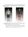
GARMENT SIMULATION IN 3D VIRTUAL DRESSING ROOM Elena FILIPESCU Textile Faculty, University “Gh. Asachi”, Street Mageron, Iasi, Romania [email protected] Abstract: The challenges of virtual garment simulation are numerous, and have attracted research efforts for more than a decade. First dedicated to the realistic simulation of the mechanical behavior of cloth, it soon evolved towards simulation of virtual garments on synthetic characters. The 3D clothing fitting on a virtual parametric mannequin is an important research topic in the garment computer design. The steps in resolving the garment fitting are the following: the parametric mannequin is obtained from the realistic body scan of the selected subject, next stage contains in noise correction of the virtual mannequin using the advanced technologies of certain education software. Once the virtual mannequin of the selected subject is obtained, it is introduced in the 3D fitting garment simulation software. The result is a garment simulation which can lead to an answer for the eternal question: how to have a perfect fit between different body shapes and one garment. Keywords: body scan, parametric mannequin, virtual environment, 2D patterns, 3D simulation, garment fit. I. THEORETHICAL SIMULATION RESULTS REGARDING THE 3D GARMENT Virtual garment simulation is the result of a large combination of techniques that have also dramatically evolved during the last decade. Cloth simulation has however matured enough to introduce its potentials to the garment industry. Garment simulation makes it easy for designers, pattern makers and apparel manufacturers to present style decisions, test the fit of a garment and create accurate and visually stunning samples in less time and share them instantly, without expensive sewing and shipping costs. Flat sketches often aren't able to truly explain a designer's vision to the development team or potential buyers. The present papers shows how efficient is to work with garment simulation, work method which make it possible for users to see the garment from any angle in a static pose or even in motion using a virtual mannequin. It can be parameterized after the customer dimension and in the 3D garment simulation it can be tested the fit between the body and the garment. Regarding the results, the designer can change the initial pattern and correct the particular garment according to the costumer needs. A pattern is a 2-dimensional representation of a 3-dimensional object; ultimately the garment will be worn by someone, and the pattern maker is responsible for the way that garment fits. Many pattern makers use 3D garment simulation to test their pattern blocks and basic shapes while they are drafting the pattern, to make sure that the balance and slopes of the garment are correct. II. EXPERIMENTAL SIMULATION RESULTS REGARDING THE 2.1 2D pattern design using the 2D PDS OPTITEX software 3D GARMENT The present paper illustrates one of the ways to obtain a garment simulation. To obtain a correct fit, the pattern must first be correctly designed in 2D and must be developed to be able to generate, starting from 2D patterns the necessary data to generate the 3D physical model of the garment and execute the simulation. The 2D skirt and blouse pattern was designed using the geometrical method, in the PDS OPTITEX CAD software. In order to desgin the patterns, can be used the function displayed in the several tool mode as it follows: Contour tool mode: Using this tool mode, you can create the important patterns line, add points and align then vertical, horizontal or by a needed direction, the pattern contour can be smothed, the pattern countours can be joined ar splited in a needed point, corners can be rounded, different countors can be joined between them. Insert tool mode: After the pattern is ready, using this working tool mode can be added on the pattern the nothces, the seam type which can be copied, duplicated or replicated for all the displayed patterns, the dart can be added, edited or cut. There is also a function for adding the buttons if there are any on the desgined garment. It also can be aded text on the patterns and pleats if there are any. Edit tool mode: After the pattern is ready, using this working tool mode can be added on the pattern the nothces, the seam type which can be either copied, duplicated or replicated for all the displayed patterns, the dart can be added, edited or cut. There is also a function for adding the buttons if there are any on the desgined garment. It also can be aded text on the patterns and pleats if there are any. Piece tool mode: After the pattern is done, it is neccesary to realize a pattern verification. Using the Piece tool mode, the patterns can be neasured to be sure are at the correct dimensions, the pattern can be joined together for a better verification or can be used the“. Grading tool mode: After all the measurement and pattern checking are done, the pattern can be graded for the according grading table. Using the Grading tool mode, gradings cotes can be aded to points, or can be copyed to different points, the grading can be fliped ore can be equaly added to severeal points. The results of using all the function and according to an algorithm the pattern for the skirt and blouse garment is presented in the figure 1.1. and figure 1.2. Figure 1.1. 2.2 Figure 1.2. Preparing the 2D patterns for the garment simulation Creating 3D cloth from 2D flat patterns requires additional information which consists of: Initial 3D position and mannequin dimension (Front, Back, Left etc.); Stitching information (What goes to what?); Define materials and texture (Stretch, Rigidity…); Colors, Prints, Logo’s, Stitch widths & textures (Shading). The work flow for obtaining the fit simulation: patterns must be created in 2D but also there is the posibility to import 2D patterns from different CAD systems. On the desgined/imported 2D patterns must be added the stitches informations and then to define the fabric and texture type. Once all these steps are done, the 3D module must be open, where the garment is positing on the virtual manequin and verify the patterns position one to another and also the pattern position to the mannequin. In the end, the simulation can be done and the result is a visualisation of the fit between the garment and the mannequin. Having this result, the desginer can modify the initial patterns till it is obtained a perfect fit. Initial 3D position and mannequin dimension OptiTex 3D gives the power to simulate cloth on a variety of body sizes and shapes. The parametric mannequin module allows interactive modification of the model’s body dimensions in real time, yielding the freedom to view the finished garment on practically any body size. First step would be to learn how to use the parametric mannequin module, change body measurements, and control the placement of measures on the 3D model. Once the model is loaded, the Body Dimensions dialog already has default measurement values for each parameter. For each parameter the model has a default location from which the measurement is taken. If you click on a slider for a parameter, or click inside its associated edit box, you can see the location of the measurement represented by a highlighted blue line. For example, if a click is done on the slider for the Waist parameter a blue line appears around the area of the model’s waist in the 3D viewer. Often, the placement of these default locations will not be exactly what you want, so the system allows you to modify their placement to any position you like. The key to changing measure placement is in using the measure tools. Stitching information and the stich verification The next step is to add the stiches information between the 2D patterns. In order to be able to realize the simulation, the garments must have stich information added on the segments whitch will be swed togheter. There are different ways to add a stitch: For the skirt pattern were used the most common stitch type as it can be noticed in the figure 2.1. The used stitched were: Segment to Segment Click on a line to be stitched, notice how a color highlights the selected segment and that the stitch cursor turns into a “double” sewing machine indicating that the next segment will connect to this one. Figure 2.1. For the blouse pattern were used more types of stitches as it can be noticed in figure 2.2.: segment o segment, point to point, segment to a point, segment to a curve. Figure 2.2. After stitching all necessary segments, we are ready to verify the connections and run the simulation, method presented in figure 2.3. Position the cloth on the parametrized manechin and now you can see the actual stitching connections in 3D. Stand alone stitches are not visible at this point At this point you have either finished stitching correctly, or maybe you are missing some stitches, or some stitches might be reversed. The simulation is now ready to be done. In order to start the simulation press the “Simulate draping” button, and the garment will be fit to the mannequin. Figure 2.3. Define materials and texture A very important fact in the garment simulation is the material mechanical propertis and also the texture. The present paper goals is not to make a reserch over the bond between the mechanical propertis of the fabrics and the garment simulation, but it is a very important matter and it will be mention the fact that the simulation was make on two typs of fabris and the mechanical properis were colected from an research made by the author in 2001. The reasrch was done in Slovenia, at the Mechanical University of Maribor and the testing was done using the KES system. In the 3D module there is the option to set the mechanical parameters of the cloth. The mechanical parameters that must be introduced are: bend, strech, shear, shrinkage, weight, friction and thickness. Ale these parameters were tested on the KESS system and must be reloaded for each time the material is changed. The present reaserch was done using the mechanical parameters for two different fabric texture. Figure 2.4. Texture 1 Figure 2.5. Texture 2 If the garment do not fit proply on the parametric mannequin or the model must be changed, all the modification can be applied on the patterns from the right side of the workng window and after that resimulate the new patterns. In figure 2.6 is prsented the way how the basic patterns wre modifyed: For the skirt pattern: the initial skirt had a product length of 55 cm and it was considered that it should be shorter so, the pattern was modified and the design was for product length 40 cm. For the blouse pattern: the end line was changed. The initial design was with straight line at the end line of the blouse, the model was changed and was used a vest line. Figure 2.6. Tension map There is an inport way how to check the pattern fit on the body, called “tension map”. Using this method it is possible to see where the garmet fits corectly and offer a confort sensation this would be displyed by green areas and blue areas and also can be noiticed the places of the garnent where it is too tyde to the body and will not allow good movement, this will be displayed with red color. Figure 2.7. Initial tension map for front skirt Figure 2.8. Initial tension mao from back skirt Figure 2.9. Initial tension map for front blouse Figure 2.10. Initial tension map for back blouse Regarding the tension map, for the first product it can be noticed that the red area, which means that the product is to tight on the body are on the hip area, meaning that the dart dimension was not corectly made. Also the blue area indicate that the garment is too lose on the waist line, the bend pattern is to big acordingly to the waist dimensions. Some pattern desgin must be aplied to the present pattern in order to obtain good fit between the product and the body. Regarding the second product, blouse, the pattern is to tight on the chest line and to lose on the arms. On the current patterns needs to be made changes in order to obtain a good tension map. Regarding the skirt product, the pattern was modifyed on the hip line in order to remove de red areas which were adding tension on the body. The modifyed pattern was at the darts position and darts dimensions. The darts were decresed . Figure 2.11. Tension map for skirt product after the patterns were modified Regarding the blouse product the patterns were modifyed in order to optain a good fit on the body. The Loose of the patterns were adjusted by decreasing the aditional value used. Figure 2.12. Tenson map for the blouse product after th patterns were modified III. CONCLUSIONS With the increased desire among customers for individualized and customized fashion products, an interest in 3D virtual garment simulation has been growing throughout the world. 3D garment simulation has used for many things, such as virtual fashion shows, online fashion communities, the virtual trying-on of garments, and more. The present paper aims to realize a dress garment simulation. The result will be the testing of the 2d designed pattern after the fitting on the virtual mannequin using specialized 3D software. The present papers shows how efficient is to work with garment simulation, work method which make it possible for users to see the garment from any angle in a static pose or even in motion using a virtual mannequin. It can be parameterized after the customer dimension and in the 3D garment simulation it can be tested the fit between the body and the garment. Regarding the results, the designer can change the initial pattern and correct the particular garment according to the costumer needs. A pattern is a 2-dimensional representation of a 3-dimensional object; ultimately the garment will be worn by someone, and the pattern maker is responsible for the way that garment fits. Creating 3D cloth from 2D flat patterns requires additional information which consists of: Initial 3D position and mannequin dimension (Front, Back, Left etc.); Stitching information (What goes to what?); Define materials and texture (Stretch, Rigidity…); Colors, Prints, Logo’s, Stitch widths & textures (Shading). After all the steps are done, and the simulation is performed, using the fit tension map, the desginer can know if the garment is a perfect fit or it must be modifyed. The tension map have 3 different colors: • blue, if the garment is loose; • green if the gharemt is perfect fit; • red if the garment is too tight. For the present paper, the garment should have been modifyed to the chest line and shoulder lines and also to the weist line. References [1] [2] [3] Garment simulation, International Journal of Clothing Science and Technology, Vol. 20 Iss: 2, G.K. Stylios. Optitex user manual. http://www.fibre2fashion.com/industry-article/26/2562/virtual-garment-simulation-a-commercial-view1.asp