1
US 20050068322A1
(19) United States
(12) Patent Application Publication (10) Pub. No.: US 2005/0068322 A1
(43) Pub. Date:
Falcioni
(54) GENERATING ALPHANUMERIC
(52)
Mar. 31, 2005
US. Cl. ............................................................ .. 345/467
CHARACTERS
(76) Inventor: Richard A. Falcioni, Sylmar, CA (US)
(57)
ABSTRACT
Correspondence Address:
BLAKELY SOKOLOFF TAYLOR & ZAFMAN
12400 WILSHIRE BOULEVARD
SEVENTH FLOOR
LOS ANGELES, CA 90025-1030 (US)
(21) Appl. No.:
10/674,443
(22) Filed:
Sep. 29, 2003
Zones, or With the remainder of an area that is coextensive
1
CHARACTER
bove-centerclcsed curve
n-cen'ter closed curve
olow-centerclosed curve
nter curve,
134
?-of-cemer curve,
hl-of‘cenler curve,
nler curve,
1 7
Il-oI-center curve,
hl-of-cenler curve,
hove-center curve,
have-center curve,
entercurve,
nler curve,
slow-center curve,
low-center curve,
145
146
147
148
e,
ulve,
urve,
EAT
COUNTS
characters. Each aid is designed so that it can suggest to a
selected from a number of Zones. The respective combina
tion is such that if contrasted With the remainder of the
Int. c1.7 ................................................... .. G06T 11/00
R
meric character is generated through the use of mnemonic
aids Which are provided to represent the alphanumeric
person a respective combination of one or more Zones to be
Publication Classi?cation
(51)
In some embodiments of the invention a desired alphanu
a
b
c
B
With and contains all of the Zones, the remainder resembles
the desired character. Other embodiments are also described
and claimed.
Mnopqlil
vW
Patent Application Publication Mar. 31, 2005 Sheet 2 0f 14
204
_JIJLIIJL_’
232
208
\
US 2005/0068322 A1
Patent Application Publication Mar. 31, 2005 Sheet 3 0f 14
208
408
US 2005/0068322 A1
Patent Application Publication Mar. 31, 2005 Sheet 4 0f 14
US 2005/0068322 A1
‘ml
U
we“23m29:586E8@E;:350
‘.i
all
I
8
i=ailIiiii§.\
N3sa
W36@Eu:2wE5>S3o8
W;@wEEm:2u6wo»52iE3so8e?0:
8l3-'
N
00
IO
Patent Application Publication Mar. 31, 2005 Sheet 5 0f 14
US 2005/0068322 A1
Fig.
7
Patent Application Publication Mar. 31, 2005 Sheet 6 0f 14
US 2005/0068322 A1
Patent Application Publication Mar. 31, 2005 Sheet 7 0f 14
US 2005/0068322 A1
‘I .I_@mi
IU I
II§__
Fig.
9
l
.I
|
l
l
ElmI- U.-I
iIlI.IIlI'‘
Patent Application Publication Mar. 31, 2005 Sheet 8 0f 14
iIlE HI'
I
US 2005/0068322 A1
m
o
F
9
LL
Patent Application Publication Mar. 31, 2005 Sheet 9 0f 14
US 2005/0068322 A1
v53.w6 E mBoE
\
\
_m:5w>=9o u:20c~8mu9=62>5t-.\m2.<I
.5Q2
2.2.
Q2:
3 :0
5Q: m2<
3“5:0Q: x52
Patent Application Publication Mar. 31, 2005 Sheet 10 0f 14
wvmli
"I
-
w
US 2005/0068322 A1
Patent Application Publication Mar. 31, 2005 Sheet 11 0f 14
US 2005/0068322 A1
Mama
]lay-0:)
\,35:0
Ew>sbmE
L35:0
mm::552DEM:moI.maEomI
359‘3:I‘2‘20 1Tn?:55woum
E‘
an
.5Q:
Patent Application Publication Mar. 31, 2005 Sheet 12 0f 14
US 2005/0068322 A1
if
ii,
1277;
Patent Application Publication Mar. 31, 2005 Sheet 13 0f 14
#5: I35:0
Emzb
US 2005/0068322 A1
F
_.
P
m
cu:
\
,
/85A6|035
Unm
b5‘2ncmI.90u-:am0o
E52358:E3
0:.5
“E=2c05m
:.~254.0
2‘
N_.
Patent Application Publication Mar. 31, 2005 Sheet 14 0f 14
1307
1310
1312
1304
;
106
7
I
l/
77,. I
US 2005/0068322 A1
Mar. 31, 2005
US 2005/0068322 A1
GENERATING ALPHANUMERIC CHARACTERS
BACKGROUND
[0001] An embodiment of the invention described below
relates to a technique for representing alphanumeric char
acters (such as the letters of the English alphabet) using a set
of graphic symbols that may have reduced information
content relative to the characters. In addition to other appli
cations, the technique may alloW fast and accurate direct
manual entry of electronic data into a device that has limited
physical space for data entry, such as a personal digital
assistant (PDA) With a touch-sensitive display screen. Other
embodiments of the invention are also described.
[0002] Small, electronic logic-controlled devices such as
PDAs are popular tools for taking notes and communicating
With others. They are battery-poWered and portable yet can
deliver signi?cant computing poWer and connectivity. Their
small siZe hoWever may preclude a full-siZe keyboard in
Which each letter of the alphabet is assigned a large, separate
key. Instead, these devices typically have a specialiZed data
input interface, such as a touch-sensitive display screen,
With a relatively small area on Which an operator draWs,
using a hand-held stylus, the character that he Wants to enter.
After the operator makes the draWing on the interface, the
device then attempts to interpret the draWing to determine
the intended character. Words and phrases can be entered in
this manner, Without using a full keyboard, provided the
device can properly interpret the operator’s handWriting. To
assist in this process, restrictions are placed on the location
in the Writing area and the path to take When the user makes
a draWing. An example of such a device is the PALM
handheld computing device that features the GRAFFITI
Writing softWare, by Palm, Inc., Milpitas, Calif.
[0003] Although the suggested GRAFFITI draWings bear
a strong resemblance to their corresponding characters, the
technique often results in the Wrong character being detected
When the pace of Writing quickens. In addition, there is a
noticeable delay betWeen the point in time that the user has
completed a draWing and When the corresponding character
appears before the user.
[0004] Another method for entering alphanumeric data is
described in US. Pat. No. 5,982,303 to Smith. That patent
describes hoW a complete set of alphanumeric characters
may be entered on a data input device having only nine keys
arranged in an array. Each character is input by entering
sequential keystrokes Which de?ne a pictograph. The patent
also alleges that an untrained operator can quickly learn the
pictographs Which correspond to each character. While some
of the pictographs employed bear a vague resemblance to
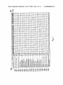
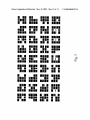
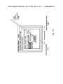
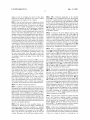
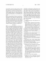
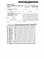
[0006] FIG. 1 illustrates a table of a set of character
features or building blocks that are in the nature of open and
closed plane curves, and hoW each character can be decom
posed into a subset of these curves.
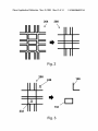
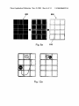
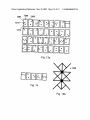
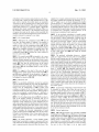
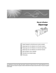
[0007] FIG. 2, shoWs a tentative matrix obtained by
assembling the features together based on their relative
positions.
[0008] FIG. 3 illustrates application of the stretched
matrix to select a combination of features that represent the
letter “b”.
[0009]
FIG. 4 depicts a complement matrix.
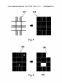
[0010] FIG. 5 shoWs regions of a solid, complement
matrix being visually contrasted With the remainder of the
matrix to form a graphic symbol for the letter “b”.
[0011] FIG. 6 shoWs examples of hoW the matrix-comple
ment approach may be used for forming more complex
graphic symbols than necessary, to obtain a more recogniZ
able graphic symbol.
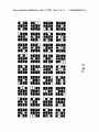
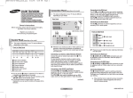
[0012] FIG. 7 illustrates a set of recogniZable graphic
symbols that correspond to the 26 letters of the English
alphabet and the 10 decimal system numerals, based on a
19-element matrix-complement approach.
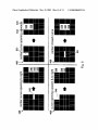
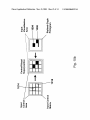
[0013] FIG. 8A shoWs hoW the 19-element complement
matrix is overlayed by a 12-element (three column by four
roW) control matrix.
[0014] FIG. 8B depicts a six-point array that can be used
instead of a grid, to suggest the ?xed locations of the regions
of a 12-region control matrix.
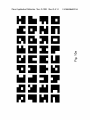
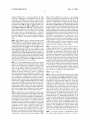
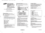
[0015] FIG. 9 illustrates 36 code con?gurations of the
19-Zone complement matrix overlayed With the 12-Zone
control matrix, highlighting selections of no more than tWo
control Zones in each code con?guration.
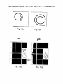
[0016] FIG. 10A shoWs 36 graphic symbols all using the
12-Zone control matrix With no more than tWo Zones in each
selection, yet still being readily recogniZable as the charac
ters they are intended to represent.
[0017] FIG. 10B depicts a styliZed glyph pictogram that is
aligned With its corresponding control regions.
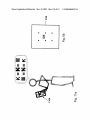
[0018] FIG. 11A symboliZes an example process of con
struction, in the mind of a user, for indicating the letter “K”.
[0019]
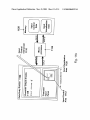
FIG. 11B shoWs in block diagram form a handheld
computing device.
their corresponding alphanumeric characters, most do not.
[0020] FIG. 11C depicts in block diagram form a hand
held computing device in Which the input control and
visualiZation areas overlap a large portion of the character
As a result, the operator may be required to spend a
output display.
signi?cant period of time learning or memoriZing the strokes
needed to enter most of the characters.
BRIEF DESCRIPTION OF THE DRAWINGS
[0005]
The embodiments of the invention are illustrated
by Way of example and not by Way of limitation in the
?gures of the accompanying draWings in Which like refer
ences indicate similar elements. It should be noted that
references to “an” embodiment of the invention in this
disclosure are not necessarily to the same embodiment, and
they mean at least one.
[0021] FIG. 12A depicts pen-doWn and pen-up actions by
a user, on a touch-sensitive screen, for selecting the regions
or Zones of a matrix.
[0022] FIGS. 12B-E illustrate the use of a sWirl action on
a touch-sensitive screen, for differentiating betWeen charac
ters that share one or more control regions or code con?gu
ration.
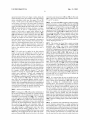
[0023] FIG. 13A illustrates another set of graphic symbols
that recogniZably represent the 36 alphanumeric characters,
While adhering to the matrix complement concept.
Mar. 31, 2005
US 2005/0068322 A1
[0024] FIG. 13B depicts a generic receiving area template
for illustrating the symbols of FIG. 13A.
[0025]
FIG. 14 shoWs a Word formed as a combination of
symbols taken from those in FIG. 13A.
electronic logic-controlled devices that do not have a full
siZe keyboard, although other applications such as paper
forms (to be ?lled in by hand and then scanned electroni
cally) may also bene?t from the technique.
[0030] A derivation of the preferred mapping betWeen
DETAILED DESCRIPTION
[0026]
An embodiment of the invention is directed to a
character representation technique in Which each alphanu
meric character is represented by a separate, graphic symbol
that is designed to be a mnemonic aid to the user. The user,
When looking at the graphic symbol, should be able to easily
determine or recall Which character corresponds to the
symbol. In addition, each graphic symbol is easy to remem
ber, because it is designed in such a Way as to be suggested
by one or more apparent, basic features of its respective
alphanumeric character.
each combination of one or more Zones and its correspond
ing alphanumeric character may be summariZed as folloWs.
First, each character is represented as a juxtaposition of
some of a set of open and closed plane curves, also referred
to as features or components. These features are like build
ing blocks and may be idealiZed into rectangles or squares,
and angular portions of such rectangles or squares. Other
shapes are, hoWever, possible. As explained in detail beloW,
there may be 19 different features needed to compose all of
the letters of, for example, the English alphabet and the 10
decimal numerals. Next, a template or matrix is created
based on the entire set of features, by abutting the features
[0027] For the user to indicate her desired character, a
group of Zones may be de?ned in a Writing area or receiving
area. Each symbol is designed to suggest to or remind the
to each other in such a Way that each feature can be visually
user of a respective combination of one or more Zones, to be
matrix). The second matrix acts as an adapter, to further
reduce the number of control regions that Will be offered to
the user for indicating a character, from 19 to, in this
selected from the group. The combination of Zones for a
distinguished from the others. This template may then be
overlayed With a smaller, second matrix (eg a 12-Zone
desired character is de?ned so that, When visually contrasted
With the remainder of the group, the remainder of the group
resembles the desired character. Each Zone of a given
example, just 12. Each character is indicated by a respective
combination may serve to highlight or suggest one or more
tWo) regions or Zones in a matrix.
selection of one or more (and in most cases, no more than
respective features of the corresponding character, via a
complementary rather than direct relationship With that
[0031] Feature-Based Character Decomposition
feature. In the following section, a derivation for a set of
[0032] FIG. 1 illustrates a table of a set of character
features or building blocks in the nature of open and closed
curves. The inventor has found that a complete set of
basic features or building blocks is given, by decomposing
each character into one or more of these basic features.
[0028] The character representation technique has been
applied to decompose each of the tWenty-six letters of the
English alphabet and ten decimal numerals, into just a feW
features taken from a set of nineteen (19) features. This
so-called feature-based representation of each character may
be used as the graphic symbol for that character. This type
of symbol is preferably depicted using a matrix of tWelve
Zones, arranged in four roWs and three columns. A motiva
tion for this particular number and arrangement of Zones is
given beloW, although it is possible to use other Zone
arrangements, as Well as a different number of Zones, for
indicating the symbols. For example, a 19-Zone matrix (that
is a direct result of the 19 basic features) may be used by
itself, i.e. Without reduction to the 12-Zone matrix, to depict
the graphic symbols. It has also been found that every one
of the alphanumeric characters may be represented by a
respective combination of no more than tWo Zones (even in
the 12-Zone matrix). This combination is also referred to as
a code con?guration.
[0029]
Due to the relative simplicity of each combination
of Zones, a user can quickly indicate her desired character by
making merely one or tWo selections on the matrix. Users
can be expected to rapidly learn the combination for entering
a character, because each combination is easily distinguish
able from another and is naturally suggested by the basic
features of its respective character. Accordingly, this is
expected to alloW the user to form entire Words and phrases
quickly and in a relatively error-free manner. Each indicated
combination can be mapped into its corresponding character
through a look-up table, thereby alloWing loW-cost yet fast,
electronic decoding of the combinations. This renders the
technique particularly effective for data entry in small,
distinct, graphic symbols may be generated, from such a
relatively small set of features or building blocks that closely
resemble their respective characters. The features are shoWn
in the roWs of the table of FIG. 1. A set of 36 alphanumeric
characters including the letters of the English alphabet
(some in loWer case While others in upper case) and the ten
decimal numerals are listed in a ?rst upper roW 122.
[0033]
Within the column beneath each character in the
?rst upper roW 122 are marked the features, taken from a left
hand column 128, that may be deemed necessary and, in
most cases, sufficient for recognition purposes. For example,
the letter “0” has only a single mark in its column, in the roW
associated With What is referred to as the on-center, closed
curve 131. In a second upper roW 124 are all of the
corresponding graphic symbols that are composed from the
features. The suf?ciency or near suf?ciency of just those
features for recognition purposes can be appreciated. In
some cases, slightly different features may be used, or
feature nuances may be added, for characters that look
similar. For example, “0” and “0” may be represented by an
on-center closed curve 131 and a beloW-center closed curve
132, respectively. In the case of “s” and “5”, and “Z” and “2”,
feature nuances may be de?ned as illustrated in FIG. 9 to
distinguish their selection processes. Note that feature
nuances, employing fragments of a feature, may also be used
simply to make a graphic symbol more recogniZable.
[0034]
The features listed in the left hand column 128 may
be grouped into three distinct categories, namely (1) closed
plane curves, (2) unshaped plane curves that open up, doWn,
left and right, and (3) right angle shaped plane curves that
open out to the four quadrants (upper-left, upper-right,
loWer-right and upper-left). In such idealiZed form, as rect
Mar. 31, 2005
US 2005/0068322 A1
angles or parts of rectangles, the curves in these three
[0041] FIG. 3 illustrates application of the stretched
categories are angular; alternatively, they may be de?ned
using smoother, less angular curves or shapes.
[0035] Note that each feature may be de?ned not only by
matrix 208 to select a combination of features that represent
inventor has found that these 19 features may be suf?cient
the letter “b”, namely the beloW-center closed curve 132 and
the curve opening upWard and to the right 146 (see also FIG.
1). Note hoW the features 132, 146 may be selected by the
user’s manual actions (indicated by the X) upon the corre
to generate the readily recogniZable set of 36 graphic
symbols, corresponding to the 36 alphanumeric characters
208. HoWever, the features, as highlighted in the right-hand
set forth in the ?rst roW 122 of the table in FIG. 1. Note also
that 33 out of the 36 can be characteriZed With at most tWo
features. And of those 33, 25 of them can be characteriZed
uniquely so that they can be distinguished from the others on
[0042] A solution to the above dif?culty may be to ?rst
provide a rectangular background to the matrix 208, and
its shape and orientation, but also by a relative location. The
sponding regions (or elements) 232 and 246 of the matrix
diagram of FIG. 3, may not easily convey the form of a
recogniZable character.
the basis of feature decomposition alone. This character
second, interpret the features as though they partition the
representation technique can also be referred to as a modular
background into smaller parts or components. This combi
nation of a rectangular background (having preferably a
solid color) that is partitioned into regions or Zones, Which
are delineated in part by basic features of a set of alphanu
meric characters, is referred to as a complement matrix 408,
depicted in the right-hand diagram of FIG. 4. The reason for
using the term “complement” Will become clear beloW.
character construction methodology, Where each character
can be decomposed into one or more modules. It should be
noted that the characters may alternatively be represented by
combinations of features other than those listed in FIG. 1.
Also, a different set of constituent features may be de?ned,
that may be more or less numerous than the 19 shoWn in
FIG. 1 and that may have different shapes and orientations.
[0036] When decomposing the characters into their con
stituent features, each character is preferably draWn to ?ll
the same vertical range. Terms like upper or loWer (or
[0043] Next, it is instructive to note What happens When,
for example, regions 532 and 546 in the solid, complement
matrix 408 are visually contrasted With the remainder of the
matrix, as shoWn in FIG. 5. A graphic symbol is formed that
above-center and beloW-center) can therefore be interpreted
bears a strong resemblance to the letter “b”. This resem
as situating a feature in the upper or loWer half of that
vertical range.
blance may become more apparent When the symbol is
vieWed from a further distance. This character representa
[0037] The features that are indicated in FIG. 1 as con
stituting each symbol may be vieWed as meeting a minimum
threshold needed to make a character representation recog
niZable and distinguishable from the other characters.
Indeed, a graphic symbol may be de?ned in a more complex
manner, using additional features or nuances. For example,
tion is advantageously achieved Without having to juxtapo
sition the features 132 and 146, as Would be needed in FIG.
3 to recogniZe that the letter “b” is being sought. The regions
532 and 546 of the matrix 408 are said to suggest the features
132 and 146 (see FIG. 3), through a complementary rather
than direct relationship With those features.
When using only the given set of features shoWn in FIG. 1,
[0044]
some characters may not be readily distinguishable from
others, such as “g” and “9”, “o” and “0”, “s” and “5” and “Z”
and “2”. In addition, to make the letter “v” more recogniZ
able and also distinguishable from the letter “u”, “v” may be
408 alloWs a feature of a character to be represented in more
represented as if it Were an upper case “Y” With a very short
It should also be noted that the complement matrix
than one Way. For example, consider FIG. 6 Where the
feature of a center curve opening to the right (reference no.
142 in FIG. 1) can be recogniZably represented by contrast
ing region 542 With the remainder of the matrix 408. An
alternative here is to visually contrast the three regions 542,
stem. This provides the effect of the characteristic “v”
vertex, thus distinguishing it from the rounder or ?atter “u”.
540, and 544. The latter combination of regions might yield
Other enhancements to make a symbol more recogniZable
are possible. Some special cases Will be addressed beloW.
a more recogniZable graphic symbol (in this case represent
ing the letter “c”). FIG. 6 also shoWs other examples of the
[0038] The Matrix-Complement Approach
matrix-complement approach for forming more complex
graphic symbols than necessary, ie the letter “u” (center
curve opening upWards 133 suggested by the complement
region 533), the letter “L” Whose graphic symbol is formed
[0039]
In addition to discovering that the characters can be
decomposed into constituent features, the inventor has also
found an effective process for indicating the graphic symbol
(and hence the desired character) by a user. First, a template
204 is formed, as shoWn in FIG. 2, by bringing the features
close together based on their relative positions (that is upper,
center, loWer), and their orientation (that is opening to the
by visually contrasting the complement region 546, and
?nally the letter “0” Whose graphic symbol is formed by
right, opening to the left, opening upWard and to the left,
visually contrasting the region 531.
[0045] Using the matrix complement technique described
above, and sometimes applying multiple compliment
etc.) Features that have an orientation associated With them
regions per feature, a set of recogniZable graphic symbols
are located at the outside of the matrix, Where the feature can
may be generated that correspond to the 26 letters of the
English alphabet and the 10 decimal system numerals as
shoWn in FIG. 7. The graphic symbols are easily recogniZed
face out in its speci?ed direction.
[0040] Next, almost all of the assembled features are
“stretched” so that they abut one another, eliminating the
intervening spaces and thereby resulting in a stretched
matrix 208 in FIG. 2. Note also that the stretched features
become the boundaries of the regions in the matrix 208 in
such a Way that most of the regions line up in roWs and
columns. The purpose for this Will become apparent beloW.
to be the characters they are intended to represent.
[0046] Another Way to understand the matrix-complement
approach may be as folloWs. Rather than being directed to
a draWing-based approach Where the features of a character,
or even a mnemonic, are positively recited by the application
of force (via a ?nger or stylus) on a receiving area, an
Mar. 31, 2005
US 2005/0068322 A1
embodiment of the invention instead indicates each charac
ter starting With a matrix of solid elements that are of the
same color or material, from Which pieces are essentially
“removed” by the user applying force to those pieces, When
entering her desired character. This leaves behind a graphic
symbol (also referred to as a styliZed, glyph or glyph-like
alphabet. For example, additional detail may be provided for
the graphic symbols that represent the characters “[”, “{”,
and “C” (upper case c), to clearly distinguish the symbol
used for the letter “c”. The graphic symbols depicted in FIG.
9 are preferred, because each of them readily maps into and
is identi?ed With the regions or Zones for their selection. It
pictogram) that closely resembles the character. Thus, it is
is believed that this aspect makes it relatively easy for people
the remainder of the matrix, or the remainder of the group
to remember hoW to designate a desired character, in the
of regions that make up the matrix, Which resembles the
feature-based, complement matrix approach.
character, once the selected regions have been removed or
visually contrasted in response to user input.
[0047] The Control Matrix
[0048] Although in the complement matrix 408 not all
roWs have the same number of regions, it is possible to
overlay a three column by four roW array of rectangular
regions or Zones over the complement matrix 408. In that
case, each of the larger elements of the complement matrix
408 may be completely contained in a separate one of the
tWelve regions. This is illustrated in FIG. 8A Where the
complement matrix 408 is overlayed by a three column by
four roW control matrix 808.
[0049]
The control matrix 808 is intended to be a more
ef?cient means for the user to enter manual actions that
indicate a desired character, by the selection of one or more
of tWelve Zones that overlay the elements of the complement
matrix 408. Note that the selection Zones in the control
matrix 808 are feWer and larger than those of the comple
ment matrix 408 and accordingly should be easier for the
user to operate.
[0050] To suggest in the mind of the user the ?xed
locations of the control regions in the control matrix 808, a
grid 810 may be displayed. As an alternative to the grid, a
six-point array 814 With a visible outside boundary 816 may
be displayed, as shoWn in FIG. 8B.
[0055] In the preferred embodiment, a graphic symbol
(eg a styliZed glyph pictogram) is made to appear, When the
user has selected a given combination of regions from the
control matrix that correspond to that symbol. In addition,
this symbol is preferably “aligned” With its corresponding
control regions. In other Words, at least a part of every
contrast area (that alloWs the symbol to be vieWed) falls
Within the corresponding control region that has been
selected. For example, in FIG. 10B, at least a part of the area
1004 falls Within the selected control region 1014. Similarly,
at least a part of the area 1008 falls Within the selected
control region 1018.
[0056] The preferred relationship betWeen a styliZed
glyph, as it appears before the user, and its corresponding,
selected control regions may also be explained as folloWs.
First, the styliZed glyph should be comparable in siZe to the
entire control matrix. Second, the outside boundary of the
styliZed glyph should be substantially co-extensive With that
of the control matrix. Both of these conditions can be seen
in the control/visual superposition diagram that depicts the
letter “e” in FIG. 10B. This alignment reinforces, in the
user’s mind, the mapping betWeen the control regions to be
selected and the corresponding alphanumeric character.
First, it does not introduce distractions and keeps the user
focused on the task at hand (namely, indicating a desired
character). Second, shoWing the styliZed glyph so aligned is
expected to help meet the user’s expectations of her desired
[0051] Mnemonic aids
[0052]
In a preferred embodiment, at most tWo selection
Zones are needed to identify any one of the 36 alphanumeric
character being invoked. This may be particularly helpful
When a character input panel before the user appears as a
solid rectangle, With no outline that shoWs the boundaries of
the control regions.
characters previously mentioned. This embodiment is illus
trated in the 36 con?gurations of FIG. 9 Where each
[0057] Aprocess for constructing a desired character may
combines an instance of the 19-Zone complement matrix
overlayed With the 12-Zone control matrix. These regions or
be described as folloWs. First, When the user Wants to
generate a particular character, he or she recalls the corre
Zones may correspond to push-buttons on a keyboard or
keypad, or to highlighted areas on a touch sensitive surface.
sponding, graphic symbol, as shoWn for example in FIG. 7.
This graphic symbol then in turn suggests the regions or
[0053]
The 36 con?gurations shoWn in FIG. 9 may also be
used as the graphic symbols or mnemonic aids. As an
alternative, an otherWise solid 12-Zone matrix depicting a
respective 2-Zone selection for a given character may be
used as the graphic symbol for that character. That is because
despite having less detail than those based on the 19-Zone
matrix, graphic symbols that use the 12-Zone matrix are still
recogniZable as the characters they are intended to represent.
See, for example, the tWo-Zone representation of each
graphic symbol depicted in FIG. 10A. Note that the outline
or border of each instance of the 12-Zone matrix does not
appear in that it is of the same color as the background
Zones to be selected, namely those highlighted in FIG. 7 or
depicted in White in FIG. 1A. This forWard process of
construction in the mind of the user is symboliZed in FIG.
11A for the example letter “K”. HoWever, the reverse is also
true. When the user has selected the correct Zone combina
tion, the remainder of the selection area or matrix Will look
like the desired character, thus con?rming for the user that
he or she has selected correctly.
[0058] System Applications
[0059] FIG. 11A also depicts a user operating a handheld
computing device 1104, such as a PDA device. As shoWn in
around each matrix.
block diagram form in FIG. 11B, the handheld device 1104
[0054] As another alternative, a more detailed graphic
symbol may be provided to represent a character and to act
as the mnemonic aid. More detailed graphic symbols may be
used to represent special characters other than those of the
display screen in Which a matrix of control regions have
been de?ned in a preferably ?at, input control area 1112.
Each of the control regions is sensitive to a force exerted by
includes a data entry portion 1108 such as a touch-sensitive
the user via his or her ?nger or via an input control
Mar. 31, 2005
US 2005/0068322 A1
instrument 1116 such as a stylus. In addition, the input
control area 1112 may be superimposed With an input
visualization area 1120 (or vice versa), so that each of the
control regions can be visually contrasted With the remain
der of the matrix When the user has selected the region. The
visualiZation area 1120 also alloWs a graphic symbol, bear
ing either the 19 Zone matrix 408 (see FIGS. 4-7), a 12 Zone
matrix 808 (see FIG. 8 and FIG. 1A), or another higher or
loWer resolution alternative, to be depicted When the control
regions are selected by the user. Some type of portable
poWer source, such as a rechargeable battery or a fuel cell
(not shoWn) is provided in the PDA device, coupled to
poWer the display screen as Well as the logic Which imple
ments the character representation technique described
above.
[0060]
FIG. 11B also shoWs a separate character output
display 1130, used for displaying the generated characters,
either in the form of their respective graphic symbols or in
a conventional, high resolution font. An alternative to this
arrangement is to locate the input control area 1112 and the
input visualiZation area 1120 so as to partially or even
completely overlap With a part of the larger, character output
display 1130 (see FIG. 11C Where the input control and
visualiZation areas 1112, 1120 (superimposed relative to
each other) overlay a large portion of the output display 1130
Where previously generated Words and characters are simul
12A), Without affecting the accuracy of the mapping
betWeen a combination of selected control regions and its
corresponding alphanumeric character. In cases Where the
character is represented by a single region, the pen-doWn
and pen-up actions remain on a single region (see the right
hand diagram of FIG. 12A). Other possible applications for
the matrix-complement techniques described above include
desktop computer systems, automated teller machines, and
mobile telephone devices Where the control regions are
typically represented by spaced apart (rather than abutting)
mechanical pushbuttons on a keyboard or keypad. In such an
embodiment, one or more key activation events may be
prescribed for each character. For example, one or more
keys may be associated With a given character, and an
activation event for each key may be de?ned as the key
being depressed or let go by the user. Note that the timing
of the activation events for a given combination may not
matter, if the combination of events is based on a combi
nation of keys that is unique to each character.
[0063] Sometimes the user may Want to undo the effect of
a region selection action for a certain character, prior to
beginning the process of indicating the next character.
According to an embodiment of the invention in Which the
PU and PD actions are used for such region selection, the
undoing or reversing process may be described as folloWs.
First, the user performs an initial PD action upon a ?rst
taneously being displayed); this alternative may be espe
region. The system then detects the ?rst region. Next, the
cially useful for very small devices 1104 such as enhanced
Watches Where display area is at a premium.
user slides the stylus out of the ?rst region, Without any PU
[0061] The device 1104 should preferably include further
logic that is designed to control the touch sensitive display
screen so that each respective combination of Zones selected
actions. NoW, if the stylus is then slid back to the ?rst region
(Without any PU actions), and is then folloWed by a PU
action off the ?rst region, the system interprets the sequence
as not invoking a character. In other Words, to undo his
by the user is visually contrasted With the remainder of the
matrix, as the operator selects the combination. This pro
duces in effect a real-time sensation in the operator of
draWing the desired character. Of course, as explained
above, the operator does not actually draW a character in the
actions, the user slides the stylus back to the ?rst region that
Was selected by the initial PD action, and then lifts the
matrix complement technique, but rather assembles it using
the feature-based, complementary approach described
[0065]
above. It should be noted that the logic circuitry may include
hardWired logic circuitry and/or a programmed processor
device having a machine-readable medium (such as random
access memory 1128) With input control data and input
visualiZation data stored therein that, When accessed by a
microprocessor 1124, performs the matrix-complement
approach described above using, for example, a table look
up to match a given input combination of control regions
With a corresponding character and its graphic symbol.
[0062] Although the matrix-complement character gen
stylus, to prevent a character from being generated.
[0064] Special Characters
There are some characters that may be too complex
to be easily represented using only a combination of regions
from the complement matrix 408 (see FIGS. 4-7). There are
also characters that look so similar to each other that a
combination of selection regions assigned for one of them
Would also be suggested for the other. One solution for
invoking these special characters, While using the same
complement matrix de?ned above, is as folloWs. First, an
association betWeen a special character and a certain previ
ously de?ned control region combination is made. For
example, the character “@” looks like the letter “a” and
hence may be associated With the same tWo-region combi
nation assigned to “a”. Similarly, the characters “[” and “{”
eration concept described above can be applied in electronic
systems having mechanical or virtual buttons as the selec
may be associated With the tWo-region combination that is
tion controls, the preferred embodiment is implemented in
be associated With another similar looking special character,
touch-sensitive screen systems that also support touch-begin
and touch-end (or also referred to as pen-doWn, PD, and
pen-up, PU) events. Using such a technique, it has been
found that each character can be identi?ed by a single stroke
of the pen or stylus on the touch sensitive screen. More
speci?cally, the ?rst region or Zone is selected With a
pen-doWn action, as shoWn in FIG. 12A for the 12-Zone
matrix. The second, and in this case the last, region is
selected by a pen-up action. In betWeen these tWo actions,
the stylus can be moved about on the character-generating
control matrix as desired (see the left-hand diagram of FIG.
assigned to the letter “c”. Alternatively, the character“ ” can
namely “<”. This is also referred to as control region sharing
by different characters, Which are assigned the same base or
initial set of regions. Next, to distinguish betWeen tWo
similar characters (that share the same initial set of control
regions or code con?guration), a special control region,
Which may be separate from the complement matrix or the
control matrix, is de?ned that may be selected by the user to
indicate one, and not the other, of the tWo similar characters.
[0066] A preferred approach to distinguishing betWeen
tWo similar looking characters, hoWever, is to de?ne a