1
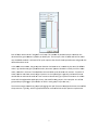
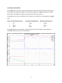
COZVIEW/COZSIM User Manual Supplement No. 1 Issued Date: August 20, 2013 This user manual supplement includes the following new functionalities: Case management WAG Schedule Case Management General Description: It is often useful in conducting a study to modify a single or a few parameters in the data and make a new simulation run. Once the simulation run is complete the user will want to compare the results (plots and 3D views) of the two (or more) case. In the case of plots, the user may wish to show multiple case results on the same plot. For 3D views the user will want to easily view the same array (e.g. oil saturation) for two different simulation cases. The goal is to ease the analysis process as the user attempts to improve or compare simulated performance of alternative cases. Cases are defined as a set of input data within a COZ project that have different property values for user selected properties. Examples of properties that may change between cases: 1. 2. 3. 4. 5. 6. relative permeability curves well completions well constraints depletion strategies layer properties * initialization properties* *The user is cautioned relative to creation of multiple cases with different volumetrics. While this is allowed, comparison of simulation results may not be appropriate. WARNING: The user should not change the structure, well locations, or grid dimensions between cases. The user is cautioned to keep a record of parameter changes between cases. While COZView allows many parameters to be changed between cases, only a few can be identified or retrieved by the case name in COZView. 1 e – Initialization Changes New Case Case man nagement may start at the Model Initialization. A seelection box h has been addeed to create aa New Case e or utilize the e existing case e. A New Case name is sugggested, but tthe user can change this n name as they wish. A comme ents field is allso provided tto aid the useer in distinguiishing betweeen cases. Thiss e filled in by th he user. The u user cannot rreturn to a prrevious case. should be This allow ws the user to change form mation properrties, PVT tab le, Saturation n function tab ble and/or initializatiion paramete ers for the new w case. All other data from m the prior caase will be rettained in the new case subje ect to change es in the Pred diction Period d Section. When the e user selects the Initialize e Model butto on the Modell Volumetricss screen will aappear along with the Simulation status w window. Once e the simulator has compl eted the initiialization, thee volumetric ppear in the table. The tab ble now has a Case Name aassociated with each values by phase will ap here is no chaange from thee previous veersion. volumetriic calculation;; otherwise th If the user has only chaanged pre‐Mo odel Initialization data to tthis point and d does not wish to change any well or fie eld constraintts or limits, th hey can proce eed directly too Run Simulation. The useer should seleect the new C Case Name crreated in Mod del Initialization Section frrom the drop pdown menu and set the EEnd Date to th he appropriatte value. The simulation ru un will be launnched accord dingly. Note th hat all well an nd field constraints and lim mits will be th he same as th he prior case.. If the user wishes to ch hange well orr field constraaints or limits in addition to o the Initialization parameeters, they may do so in the aappropriate sscreens. Be su ure to Save w when changess are made. W When the userr is ready to ssubmit the ne ew simulation n run (Run Sim mulation), theey should select the new C Case Name created in n Model Initia alization Secttion from the dropdown m menu and set the End Datee to the appropriaate value. Sele ect GO to launch the simulation run. New Case e – Prediction n Period Chan nges Only If the user wishes to crreate a new C Case that is baased on chan ges to well an nd field consttraints and lim mits, but does not require changes to Mo odel Initialization data, theey can changee the data in the appropriaate screens. In the Field/Facility Param meter/Controlls screen seleect the correcct Case in the Show Constrraints e. (As a new ccase cannot b be created on n the Field/Faacility for box. Be sure to Savve when changes are made Paramete er/Controls sccreen, this maay require the e new case too be defined on the Run Simulation scrreen, a refresh of the Contro ols screen, an nd selection o of the new casse on the refrreshed Controls screen. 2 e user is readyy to submit th he new simulation run, a N New Case can n be created aat the Run When the Simulatio on screen. Be sure the new w case name is selected aftter creating th he New Case. Select GO to o launch the e simulation run. All well aand field dataa changes willl be associateed with the neew case name. Simulatio on Results All plots, ttables and 3D D Views contaain a selection n box for the Case. All prio or cases run in n the project will be availab ble for viewing in the appropriate displaay. 3 Case Com mparison Plots in the Simulation Resultts menu allow ws the user to o compare sellected field leevel results on n any of the caases run in a project on the same displaay plot. 4 Case Sum mmary The user ccan view a table of all case es run in the p project underr Case Managgement in Utility Function ns in the Proce ess Explorer se ection. The co omments field can be alteered by selectting a case and the Edit bu utton. Cases can n also be deletted by selectiing the case aand the Delette button. The statuss of the proje ect data base (layer properrties, well connstraints, field d constraints,, etc.) is consistent with the last case run o only. (SQL datta bases for p prior simulatioon runs are N NOT retained..) The user is d not to delete the last casse run unless all cases (exccluding the “b base” case) arre being deletted cautioned and the “b base” case is being re‐form mulated. Dele eting the last case run mayy result in an incomplete d data base and impact subse equent simulaation runs in tthis project. File Naming Conventio on The file naaming conven ntion has bee en changed to o include the case name in n addition to tthe project naame. A typical ffile name is now Projectna ame_Casenam me.COZOUT oor Projectnam me_Casenamee.COZdat. 5 Be sure to o keep in min nd the rules co oncerning scrreen refreshinng. A new ca ase will not ap ppear in a Ca ase box if the e particular sccreen has nott been refresh hed since thee creation of tthe new casee. WAG Sch hedule General D Description: Many CO2 2 injection prrojects utilize a process refferred to as W WAG (water‐aalternating‐gaas). Injection into designate ed wells is varried between CO2 and watter on a definned schedule. In theory thiis maximizes use of the scaarce CO2 reso ource and provides mobility control for the advancin ng CO2 front. A new functionality has been added to COZView to makke schedulingg of the WAG process easier. Prior to th his, eduling had to o be manually specified. C COZSim has beeen able to handle this pro ocess from th he WAG sche beginningg. Establishiing WAG Inje ection Wells In the We ell Constraints section each well used in n the simulatiion must be identified with a specific W Well Type. A ne ew Well Type e has been added, WAG W Well. The user must identifyy the injection wells that w will be used in n the WAG prrocess, when they will starrt the WAG, t he maximum m individual w well water and d gas injection rrates and the e maximum in ndividual botttom hole injecction pressurre. The gas injjected duringg a WAG cycle can be hydrrocarbon gas (HCG) or CO2 2. This will bee identified in n the Field/Faacility Paramete ers/Controls ssection. Selecct Done to save. Setting W WAG Cycle Sch hedule The user m must then select the WAG G Schedule bu utton. Select YYes to the savve query. Thee first time th his screen is e entered all wells previouslly identified aas WAG wells will be show wn in the left U Unassigned column. 6 Each of th hese wells mu ust be “assign ned” to a Grou up. The numbber of possiblle Groups is b based on the duration o of the gas and d water injecttion per WAG G cycle. The c oncept is that all WAG weells will be acttive once the W WAG schedule is initiated.. A full cycle rrequires that all wells havee injected water and gas fo or the defined durations once e. In the WA AG screen abo ove, the gas in njection duraation has beenn set to 3 mo onths by the u user (the defaault value is 1)). Based on th he gas injectio on duration, tthe water injeection duratio on is initially set to the sam me value; 3 m months in thiss case. This esstablishes the e total WAG ccycle duration n at 6 monthss – 3 months of water inje ection and thrree months o of gas injection. As the injeected gas is tyypically purch hased from an n outside so ource and mu ust be used on n a near consstant volume basis; gas injection must o occur in at leaast some wells throughoutt the WAG cyycle; hence, th he need for tw wo groups in this examplee – one of thee groups alw ways injectingg gas. (The nu umber of wells in each grooup is up to th he user.) The user ccan assign the e wells to gro oups by draggging each wel l from the Unnassigned column to one o of the Group columns. Typicaally, wells are grouped based on surfacee facilities and/or pattern requirements. 7 Select OK K to save. Note thatt the WAG sch hedule will be e repeated in the simulatioon run until the run complletes or the w well types are changed for the WAG wellls by the user in the Well Constraint seection. The gaas and water used in each w well in the WAG cycle can be changed llater in the simulation run n period in thee volumes u Well Consstraints scree en, but the injjection duratiion times durring the WAG G cycle cannott be changed. The numb ber of monthss of water injection relativve to the num mber of month hs of gas injecction can be changed w with the slide e bar. The durration of wate er injection caan be changeed to multiplees of the gas injection d duration – in this case 3 m months of gas,, 3, 6, 9, etc. m months of waater. Changing the water injection d duration will change the to otal WAG cyccle duration. TThis in turn ch hanges the number of posssible groups. Once the WAG groups have been esstablished the user can vieew the well constraints for all wells in aa given grou up by selectin ng a group fro om the dropd down menu inn the top left corner of thee Well Constrraints screen. 8 AG Implemen ntation Group WA As describ bed above, th he number of Groups is dependent on tthe duration o of injection fo or water and gas. The user d does not need to place we ells in all of th he Groups. Hoowever, not d doing so will rresult in somee portion off the total WA AG cycle duraation being caarried out witth no gas injection. If multiple e Groups (sayy 3) are requirred, the cycle e sequence is as follows for a total WAG G cycle througgh all wells: Group Fiirst Gas Injection Period 1 2 3 Gas Water Water Second Gas Injection n Period Water Gas Water TThird Gas Injeection Period Waterr Waterr Gas The well p plot below is an example o of a 1 month C CO2 injectionn/1 month waater injection WAG cycle starting in n 1/1/2014 affter one year of production n. 9