1
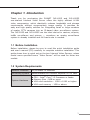
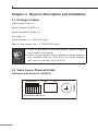
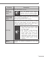
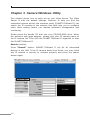
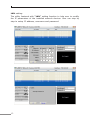
Internet Video Server IVS-H125 / IVS-H125P Quick Installation Guide Table of Contents Chapter 1. Introduction.................................................................... 3 1.1 Before Installation................................................................ 3 1.2 System Requirements.......................................................... 3 Chapter 2. Physical Description and Installation.................................. 4 2.1 Package Content.................................................................. 4 2.2 Video Server Physical Details................................................ 4 2.3 Video Server Installation...................................................... 9 Chapter 3. Camera Windows Utility..................................................10 Further Information........................................................................14 Chapter 1. Introduction Thank you for purchasing the PLANET IVS-H125 and IVS-H125P one-channel Internet Video Server offers the highly efficient H.264 video compression, which drastically reduces bandwidth and storage requirements without compromising image quality. It provides an easy and high quality solution for integrating small or large numbers of analog CCTV cameras into an IP-based video surveillance system. The IVS-H125 and IVS-H125P are the ideal choice for casinos, airports, traffic surveillance and prisons — anywhere an analog surveillance system is already installed and full frame rate is needed. 1.1 Before Installation Before installation, please be sure to read this quick installation guide and user’s manual (CD) carefully to complete machine installation. This guide shows how to quick set up the two Internet Video Servers, unless model name specified terms “Video Server” will be used for these two models. 1.2 System Requirements Network Interface 10/100Base-TX Ethernet Monitoring System Recommended for Internet Explorer 8.0 or later System Hardware CPU : Intel® Core™ i3 Processor or faster Memory Size : 2GB or more VGA card resolution : 1920 x 1080 or higher VGA card memory : 1GB or above 3 Chapter 2. Physical Description and Installation 2.1 Package Content Video Server Unit x 1 User’s Manual CD-ROM x 1 Quick Installation Guide x 1 A/V cable x 1 Power Adapter x 1 (IVS-H125 only) Male to Male power line x 1 (IVS-H125P only) Note 1.If any of the above items are missing, please contact your dealer immediately. 2.Using a power supply with a different voltage that the one included with the IVS-H125 will cause damage and void the warranty for IVS-H125. 2.2 Video Server Physical Details Left-hand side Panel for IVS-H125 1 2 3 4 PWR 5 6 H.264 Internet Video Server 4 LAN VIDEO IN IVS-H125 DI/DO/RS-485 Left-hand side Panel for IVS-H125P 1 2 3 4 PWR LAN VIDEO IN IVS-H125P DI/DO/RS-485 5 6 PoE H.264 PoE Internet Video Server Interface Description This Video Server provide a general I/O terminal block with one digital input and one output for device control. It has 6 Pins that from left to right that are 12V DC power supply (50mA maximum), Alarm Input, GND, Alarm Output, D+ terminal of RS-485 and D- terminal of RS-485. Name DI/DO/ RS-485 Number Function 12VDC 1 DC 12V (50mA maximum) DI 2 Digital signal input GND 3 GND DO 4 Digital signal output 485+ 5 RS485 data + 485- 6 RS485 data - Note The RS-485 of IVS-H125 is master that can control external scanner or PTZ camera. 5 RJ-45 Connects to 10Base-T Ethernet or 100Base-TX Fast Ethernet cabling. This Ethernet port built N-Way protocol can detect or negotiate the transmission speed of the network automatically. Please use Category 5 cable to connect the Network Camera to a 100Mbps Fast Ethernet network switch or hub. In the LAN socket, there are two LED embedded: LAN LED (green color) This LED will be flashing while network accessing via Ethernet. Power LED (orange color) This LED is used to indicate whether DC power is on or not. In addition, this LED will be flashing while network accessing via Ethernet. Video In You can install an analog camera and connect it to video-in jack. Right-hand side Panel for IVS-H125 5V DC A/V Out MIC In Reset Micro SD Right-hand side Panel for IVS-H125P 12V DC OUT A/V Out Micro SD 6 MIC In Reset Interface Description The input power is 5V DC. 5V DC (IVS-H125 only) 12V DC Out (IVS-H125P only) Note ONLY use package power adapter supplied with the product. Otherwise, the product may be damaged. The IVS-H125P provides 12V DC out through power jack to analog camera. The max output is DC 12V / 400mA. Audio/Video-out Jack allows this device to output audio and video signal. Use the attached A/V cable to connect A/V device where white cable is for audio and yellow cable is for video. A/V Out Note MIC in 1.The white jack is used for audio output, and yellow jack is used for video output. 2.The IVS-H125 could determine the monitor use NTSC or PAL format signal, and output the fitting video format to monitor automatically. Please connect the video jack (yellow) with monitor properly before power on the machine. Connect an external microphone to the Video Server. 7 Reset This button is hidden in the pinhole. This button is used to restore the all factory default settings. Sometimes restarting the Video Server will make the system back to a normal state. If the system still got problems after restart, user can restore the factory default settings and install it again. To restore the device, please follow the steps below: a.Insert the paper clip or any proper tool and press and hold the button down continuously. b.Hold it at least 5 seconds and release the tool. Then the device has been restored to default settings and reboot again. Note Micro SD Card Slot Note 8 Restoring the factory default setting will lose the all previous settings included IP address forever. User needs to run the PLANET IP Wizard II program to search the device and configure it to let the device work properly again. User can insert a micro SD card into this slot for recording. 1.ONLY use package power adapter supplied with the internet. Otherwise, the product may be damaged. 2.Please DON’T plug DC 12V power into the power jack that will damage your IVS-H125. 2.3 Video Server Installation 1.Attach video source to Video Server To use Video Server, user must supply video source to Video Server. Connect the BNC terminal of camera to the Video Server video input and make sure to power on camera first. 2.Attach Audio source Video Server (option) If user needs not only video stream but also audio stream, then the audio source should be attached to Video Server. Connect the audio device’s line output to the Video Server MIC-in and make sure to power on your camera or audio device first. 3.Plug-in Ethernet cable into RJ-45 connector Connect an Ethernet cable to the LAN socket located on the Video Server panel and attach it to the network. 4.Connect RS-485 D+ and D- (option) When users would like to apply a camera with P/T/Z function, they usually need to connect their communication port (for camera control) through RS-485. After RS-485 was correctly connected to D+ and D-, the remote users could control the camera movement through internet. 5.Connect the attached power adapters to Video Server and plug-in adapter into power outlet. 6.Done. 9 Chapter 3. Camera Windows Utility This chapter shows how to quick set up your Video Server. The Video Server is with the default settings. However to help you find the networked camera quickly the windows utility (PLANET IPWizard II) can search the IP cameras in the network that shall help you to configure some basic setting before you started advanced management and monitoring. Please insert the bundle CD disk into your CD/DVD-ROM drive. When the welcome web page appears, please click your IP camera name on the IP camera list. Then click the PLANET IPWizard II hyperlink to start the PLANET IPWizard II. Search function: Press “Search” button. PLANET IPWizard II will list all networked devices in the LAN. If the IP camera doesn’t be found, you may check this IP camera is connect to network properly and press the search button again. 10 View function: If PLANET IPWizard II finds network devices, View button will be available. Please select the device you want to view and click the View button. Furthermore you could double click the left button of mouse to link to the network device by browser. 11 LAN setting: The utility featured with “LAN” setting function to help user to modify the IP parameters of the installed network devices. User can step by step to setup IP address, username and password. 12 Note 1.If no IP address is assigned within 30 seconds, the networked device will automatically assign 192.168.0.20. User may now open your web browser, and key in http://192.168.0.20 in the address bar of you web browser to logon IP Camera’s web configuration page. 2.Power Line Frequency If you found the video image is flash, you may need to choose 50 or 60 Hz frequency (depends on different country). Worldwide power line frequency table can be found in the user’s manual chapter Appendix. After connected to networked device, the device will prompt for User name and Password. For the first time, please enter: admin as username and password to continue Web Management. If difficulty is met, please refer to the following steps to establish the connection: The networked device must be installed and powered ON. If the networked device’s default IP address (192.168.0.20) is already used by another device, the other device must be turned OFF until the device is allocated a new IP address during configuration. 13 Further Information This guide is used to help you startup your Video Server settings. It is also recommended to check the user manual in CD disk for more details of the system and user configuration. 14 This page is intentionally left blank This page is intentionally left blank