1
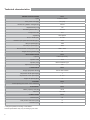
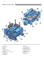
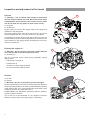
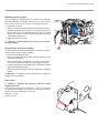
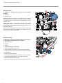
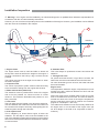
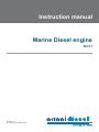
Instruction manual
Marine Diesel engine
N3.21
13122011-D
MU_N3.21_970313240_ENG
Technical characteristics
ENGINE SPECIFICATIONS
Cycle
4 strokes, Diesel
Max. power - kW (hp)*
15,4 (21)
Number of cylinders / Arrangement
3 in line
Displacement (cm3)
Fuel timing before TDC (°)
Compression rate
Aspiration
Bore x stroke (mm)
719
20 to 22
23:1
Atmospheric
67 x 68
Maximum rpm speed at full throttle (rpm)*
3600
Idle rpm speed (rpm)*
1050
No load rpm speed (rpm)*
3820
Recommended cruising speed (rpm)
Weight without gearbox (kg)
INJECTION SYSTEM
Injection
2880 - 3240
97
N3.21
Indirect (E-TVCS)
Injection order
1-2-3
Injection pump
BOSCH MD Mini type
Injection pressure (bar)
LUBRICATION
Oil type (temperate climat)
140
N3.21
API CF-SAE 15W40
Oil pressure at idle speed (bar)
1
Oil pressure at max speed (bar)
2 - 4.5
Engine oil capacity (litre)
COOLANT
Coolant (litres) (50% water - 50% antifreeze)
3
N3.21
4
ELECTRICAL
N3.21
Battery capacity mini (Ah)
35-50
Alternator
CONNECTIONS
12V / 70A
N3.21
Exhaust (mm)
40
Fuel (suction and return) (mm)
8
Seawater (mm)
20
* At engine flywheel, according to ISO 8665-1.
Certain specifications may vary according to your order
2
N3.21
Main parts of the engine
20
9
21
10
6
8
19
14
4
20
5
11
17
18
7
1
13
16
18
15
3
2
12
18
Non-binding photographs. The coupled equipment and accessories can vary according to your level of equipment.
1. Alternator
2. Alternator belt
3. Starter
4. Air filter
5. Injection pump
6. Acceleration control
7. Fuel filter
8. Water injection exhaust elbow
9. Oil filler port
10. Oil drain port
11. Oil gauge
3
12. Oil filter
13. Heat exchanger
14. Coolant filler port
15. Sea-water pump
16. Exchanger drain plug
17. Coolant pump
18. Flexible suspensions
19. Gearbox
20. Hoisting rings
21. Anode
Inspection and adjustment of the levels
Oil level
B
I Warning !: The oil checks must always be performed
with the engine stopped and cold. Be careful, these fluids
are flammable. Do not smoke in the vicinity of these fluids
and do not allow for any sparks or flame in the vicinity.
A. Oil gauge
B. Oil filler port
Engine casing oil: remove the gauge, wipe off the gauge and
reinstall it in the gauge tube.
Pull out the gauge again and check the oil level. It should be
located between the min. and max. positions on the gauge.
If necessary, top up the oil level: open the air filler port, pour the
recommended oil (see technical appendices) to reach the max
level indicated on the gauge without exceeding the max level.
Close the oil filler port.
Draining the engine oil
I Warning !: Hot oil can burn. Avoid any contact with the
A
A
skin. Observe the environment protection rules.
A. Oil drain port
The oil is removed using a drain pump, preferably: engine
slightly warm.
• Fully pump out all the oil
• Fill with new oil
• Check the oil level using the gauge
• Do not exceed the maximum level
Air filter
A. Air filter
B. Clamps
A
I Warning !: Be sure no impurities get into the engine.
Remove the clamp from the hose and remove the filter. Remove
the spring inside the filter. If necessary, clean the filter by washing
it with soapy water. Then, rinse the filter with clear water. Press
the filter to remove any water and to dry it.
NANNI DIESEL has designed a cleaning kit which is suited to
certain models of air filters.
Use of this kit is recommended on our engines to perform
effective cleaning and ensure good engine « breathing ».
4
B
Inspection and adjustment of the levels
Bleeding the fuel system
The fuel system is self-priming but it needs to be manually
bled when the filter is changed, after it runs out of fuel or after
work on the system if it has run dry or it has been emptied.
• Open the fuel valve
• Place a container beneath the bleed screw A and loosen it.
• Activate repeatedly the priming pump by pressing the lever
B until fuel with no air bubbles flows through the bleed
screw. If the fuel is not flowing after few minutes, rotate the
crankshaft a quarter turn.
• Tighten the bleed screw A
A
C
I Warning !: Avoid emptying all the fuel in the filter
during bleeding.
Replacing the fuel filter cartridge
This filter treats the water and impurities contained in the fuel
before it flows into the injection system.
• Cut off fuel intake at the tank.
• Place a container below the filter and then dispose of the
used filter cartridge C.
• Refit the new filter by attaching it securely to the engine.
Turn up the hoses on the filter by squeezing the clamps.
• Loosen the bleed screw to bleed the air, open the fuel valve
again and bleed the system.
• Start the engine and check that the assembly is properly
sealed
I Warning! : Used filters must be disposed of in containers
designed for this purpose.
Zinc anode
I Warning !: Perform this operation with the engine
stopped and cold.
A zinc anode forms part of the exhaust elbow . It serves as
an anticorrosion anode. The anode must be replaced when
more than 50% of it has been consumed.
Diameter : 10 mm
Length : 16 mm
B
Inspection and adjustment of the levels
Alternator belt
B
I Warning !: Perform this operation with the engine
stopped.
A. Alternator
B. Alternator belt
Regularly check the tensions of the alternator belt. Tension
the belt between the pulleys in accordance with the tension
or deflection given in the technical characteristics using a
DENSO meter.
Inspect drive belt : Visually check the belt for excessive
wear, frayed cords, etc. If any defect has been found, replace
the drive belt. If the belt has chunks missing from the ribs, it
should be replaced.
Check that it fits properly in the ribbed grooves. Check with
your hand to confirm that the belt has not slipped out of the
groove on the bottom of the pulley.
A
Seawater pump
I Warning !: Close the seawater intake valve as there is
a risk of water penetrating into the engine.
A. Seawater pump
B. Impeller
C. Gasket
• Close the seawater intake valve
• Close the seawater pump cover
• Using a channel lock pliers, remove the worn Impeller
• If the rotor shows any signs of cracks or defects, it should
be replaced
• Clean the parts preserved
• Fit a new rotor by applying a clockwise rotary movement
• Install the seawater pump cover using a new seal
• Open the seawater intake valve
• Start-up the engine and check for any leaks in the circuit
6
B
A
C
Inspection and adjustment of the levels
Coolant level
B
I Warning !: When filling the cooling system, the
coolant level must be checked after 10 minutes of
use since the system purges itself automatically. Top
up if necessary.
A. Coolant plug
B. Expansion tank
Turn the filler plug up to its first stop to allow the pressure
in the system to escape before removing the plug. Inspect
the fluid level.
The level should be between the lower edge of the
filler neck and the level pin (if equipped), respectively
representing the minimum and maximum level in the
expansion chamber.
Top up if necessary using a fluid comprising 50% water
and 50% antifreeze.
Degassing procedure
• Make sure that the drain plugs (block, heat exchanger)
are closed
• Open the vent plugs C and D (heat exchanger, clamp
by-pass)
• Open the filler plug A and fill with the recommended
liquid
• Close the vent plug when the liquid escape from it
• Finish the filling of the exchanger
• Close the filler plug
• Fill half the expansion chamber by the filler plug B
A
C
D
Installation Inspection
I Warning! : Your engine must be installed by an authorised shipyard or a qualified Nanni Industries representative in
accordance with the on board assembly instructions.
However, you can check some important points on the installation of the engine. However, your installation can be different
than the one that is indicated in this chapter.
6
5
3
waterline
7
4
1
2
1. Engine frame
The engine frame must be solid and able to absorb all
the dynamic stress as well as the weight of the engine. It
must be connected to the hull by a big a surface area as
possible.
The engine must not be at an angle of more than 15° when
the boat is stopped.
2. Propeller shaft
The choice of propulsion system must be made according
to the restrictions arising from the engine and the boat.
3. Water exhaust box (waterlock)
The waterlock must be positioned as close to the engine
and as low as possible. Its volume must be of 5 litres
minimum. The maximum allowable back pressure is 10.5
kPa (1.523 PSI).
4. Hull outlet
The hull outlet must be located 15cm above the water line.
The tube between the exhaust box and the hull outlet must
form a swan-neck shape to avoid any water getting into the
exhaust system through the hull outlet.
5. Anti-siphon valve
This is obligatory on boats whose engine is below the
waterline. The anti-siphon valve must be installed at the
end of the seawater system before injection in the exhaust
elbow and must be positioned above the waterline, between
0.5 and 2 meters.
8
6. Seawater filter
This must always be positioned at least 15cm above the
waterline.
7. Through-hull valve
On yachts and boats that do not go above 12 knots, the
water inlet must be turned towards the end of the boat.
On motor boats that go over 12 knots, the water inlet must
be turned forwards.
Engine room
The temperature inside the engine compartment must not
exceed 50°C with a maximum difference of 20°C with the
outside temperature.
Slow boats must have a ventilator fitted. Fresh air from the
front is circulated from front to back. The front air intake is
located low down at the front of the engine compartment
and the outlet high at the back for optimum air circulation
(engine air consumption : 160 m3/h).
The cables and extensions must be securely fastened to
the engine and / or on the walls of the engine room (do
not let it dangle in the hold or let it exposed to water or
moisture).
Installation inspection
Fuel supply system
The fuel tank of the engine must be placed as possible
at the same level or slightly higher than the engine.
The return pipe must be placed under the mini level
of the fuel tank.
The max height between the fuel pump and the
mini level of the tank is indicated on the right. The
standard pump is capable of sucking the fuel to a
height of 0.5m. An electric pump has to be installed
beyond this value.
1. Tank
2. Prefilter
3. Fuel feed pipe Ø8 mm
4. Electrical pump (option)
5. Engine fuel pump
6. Return fuel pipe Ø8 mm
Pump
Max height (m)
Standard pump
0.5
Electrical pump
1.8
2
4
5
3
Electrical installation
An incorrect or faulty electrical installation can
cause leakage currents that can affect the galvanic
protection of the engine and damage the engine
subsequently.
The installer must ensure to take all necessary
precautions to protect the engine against corrosion.
Auxiliary 12V output on instruments panel
The A4, B4 and C4 panels are equipped with an
auxiliary output of 12V / 3A.
The interfaces linking the panels to the engine are
fitted with a fuse.
9
6
1
Instrument panel
The instrument panel provides you with important information on the engine when it is in operation. Regularly check this
information when the engine is running.
2 ranges of instruments panels are available. Only the position and / or appearance of the instruments and / or the icons
vary depending on the type of panel. All panels are not composed of all these elements.
1
15
10
5
04
20
RPM x 100
1. Revolution counter
2. Hour-meter/Voltmeter
3. Engine oil pressure
4. Coolant temperature
4
3
25
30
2
1
20
0
35
0
bar
0
3
80
60
4
5
40
60
180
40
220
105
80
psi
100
°C
250
120
°F
2
Battery charge. This warning light comes at ignition. If this warning light comes on while the engine is
running, this means there is a charging fault in the alternator.
Coolant temperature warning light. This light comes on and an alarm goes off in the event of overheating
in the cooling system.
Engine oil pressure warning light. This light comes on when the pressure in the lubrication system is too
low.
Pre-heating. This light is on when the spark plugs are pre-heating the combustion chambers (if your engine
has these).
Water in the diesel filter warning light (optional). This light comes on when there is too much water in
the diesel filter.
Ignition. This light indicates that the ignition is on.
Operation of an engine equipped with an Eco4, A4, B4 or C4 panel:
To start the engine :
1. Put the throttle in the neutral position.
2. Put the key into the ON/STOP ignition.
3. Turn the key a quarter turn to the right. All the warning lights will come on and it will make a sound signal. This
stage allows you to check that these elements are working properly. After a few moments, only the oil alert and battery
charge lights will remain on.
4. Press the START button at halfway to start preheating. Hold the button for 5 to 15 seconds, depending on
ambient temperature, in order to let the engine preheat. Press fully to start the engine.
I Warning !: Never press the START button when the engine is running.
Stopping the engine:
Turn the key counter clockwise. The engine switches off and all the warning lights go out.
The operation of the ECO3, A3, B3 and C3 panels is explained in the user manual reference 970313180 that is also
delivered with the engine.
10
Instrument panel
Eco3
Eco4
START
ON / STOP
!
STOP
A3
A4
20
15
RPM x 100
25
30
10
35
5
0
40
START
ON / STOP
STOP
B3
B4
15
20
25
RPM x 100
30
10
35
5
0
40
80
60
180
40
100
220
105
ON / STOP
250
120
START
°C
°F
STOP
C3
C4
15
20
RPM x 100
10
25
30
35
5
0
2
1
20
0
0
bar
3
80
60
4
5
40
60
180
40
105
80
ON / STOP
psi
START
°C
STOP
11
40
°F
100
220
250
120
Nanni Industries S.A.S.
11, Avenue Mariotte - Zone Industrielle
BP 107- 33260 La Teste France
Tel : + 33 (0)5 56 22 30 60
Fax : +33 (0)5 56 22 30 79
E-mail : [email protected]
© 2009 - Nanni Industries SAS
The images, text and information contained in this document are based on the product’s features at
the time of publication. Nanni Diesel reserves the right to modify this document without prior notice.