1
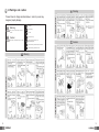
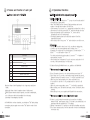
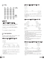
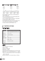
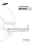
Open Voice Intercom System Model No. CM-810M 513-11, Sangdaewon-dong, Jungwon-gu, Seongnam-si, Gyeonggi-do, Korea Int’l Business Dept. : Tel.; +82-31-7393-540~550 Fax.; +82-31-745-2133 Web site : www.commax.com Printed In Korea / 2008. 12 • Thank you for purchasing COMMAX products. • Please carefully read this User’s Guide (in particular, precautions for safety) before using a product and follow instructions to use a product exactly. • The company is not responsible for any safety accidents caused by abnormal operation of the product. Contents 1. Greeting ……………………………………………………………………… 1 2. Warnings and Caution ………………………………………………… 2 3. Names and function of each part ………………………………… 4 4. Operational functions ……………………………………………………… 5 5. Wiring ………………………………………………………………………… 6 6. Power Specifications …………………………………………………… 6 7. Specifications and features …………………………………………… 8 Level-B product Instructions for users The product is registered for electromagnetic compatibility for household use and can be used in all areas including residential areas. 1. Greetings Thank you very much for purchasing of COMMAX products. Please read carefully this user manual and follow its rules. This intercom can be used in offices, and shopping outlets, and provide convenience to use communication on long distances. 1 2. Warnings and caution Please follow the things described below in order to prevent any danger or property damage. Prohibition. Warning No disassembly It may cause a serious damage or injury if violated. No touch Caution Must follow strictly. It may cause a minor damage or injury if violated. Shows plugging out the power cord without an exception Cleaning & Use Warning Caution Shows the warning and caution for an electric shock. Shows the warning and caution for a fire. 2 Power & Installation Cleaning & Use Power & Installation Warning 3 3. Names and function of each part -1 Name of eac part of CM-810M 4. Operational functions 4-1 Setting methods before usage and precautions 1) Setting of Melody ID - If you press for 2 seconds button“ * ” , beep voice will sound and bell sound will enter setting mode. - Word“Sd (SOUND)”will be shown in Display window, and current number of melody (initial number: 01) will flicker. - At this moment, if you press 1 or 2, appropriate melody will be in effect. - After melody is selected, push button“ # ” and finish melody selection. - By pressing melody selection and button“ # ” , device will be automatically enter to ID setting mode - ID in display window, and current ID (initial number: 01) will be sequentially flickered. - After setting of ID is done, press“ # ”and setting for use will be over. NO Description ① Speaker ② FND display unit ③ Ten key ④ PRIVACY function ⑤ LOCK(Hands-free communication) ⑥ TALK(Conversation) ⑦ Receiver Volume Control ⑧ Call Sound Volume Control Dial ⑨ MIC •Receiver Volume Control: Regulating of voice of opponent, coming from outside. •Calling Out Volume Control: it regulates volume of calling sound. •PRIVACY Button: when this button is pushed, even under communication, voice of this person will not be transmitted to the other party. (preventing of eavesdropping is possible) As CM-810M does not have a handset, you should press“Talk”button, during conversation, and press again one more time“Talk”button in order to finish conversation. 4 2) Precautions - Setting of ID should be done from 1 to 10 according to wiring state. - In order to go over among Melody and ID setting, press“ * ” . (Example): For setting only ID : pressing about 2 seconds button“ * ”+ button“ * ”+ set ID number + button“ # ” For setting only melody: pressing about 2 seconds“ * ”+ Number of setting melody + button“ * ” - After entering into setting mode, if you do not press any button for 10 seconds, it will automatically go to initial state. 5-2 Master Station_CM-810M How to use, guidelines for CM-810M ** When you want to call and begin to talk 1) Press ID number of device to be called and then press button“ # ” . 2) If bell lasts over 1.5 seconds, conversation mode automatically opens. Example: Calling to ID number 1: press“ 1 + # (Bell sound will occur) ” - When you press wrong number, error beep sound will occur. (It is possible to call from 1 to 10, and impossible to call into its ID number). - When you enter wrong number, press“ * ”and it will be annulated. 3) When calling, press Talk button and speak, release Talk Button, when listening. When talking is over, press again button 「#」 and finish conversation. ** When you are called from other unit and want to speak 1) If there is a call coming from another unit, you will see in display window“A(call)”words appear, after 1.5 seconds it get automatically in to speaking mode with appearing of“N”in display. 2) During of transmission it is possible to talk without handling any button. 3) If you press privacy button, it will be impossible to make eavesdropping over master unit. 5 - In case of usage of 12V/1A as it is in picture, maximum 4 units will be connected. - It is needed to wire adaptor and first CM-810M at maximum closest way within 1 meter. - It will possible to wire in parallel way by every 50 meters. 5. Wiring 6-2 When we use only one RF-1A(DC12V/1A) (Distance 100M) 6-2 When we use only one RF-1A(DC12V/1A) (Distance 100M) - It is needed to wire adaptor and first CM-810M at maximum closest way within 1 meter. -A distance between and second units of CM-810M be about - It is 6-3 needed to wire adaptor and firstfirst CM-810M at maximum closest way within 1 will meter. When we use two RF-1A (DC12V/1A). (Distance 50M / 100M) 100between meters. When we usefirst two and RF-1A (DC12V/1A). (Distance 50M / 100M) - A6-3 distance second units of CM-810M will be about 100 meters. 6-3 When we use two RF-1A (DC12V/1A). (Distance 50M / 100M) 5-1 Wiring method - This product use LINE CORD terminal for wiring. 1) Terminal 10P: It connects with LINE CORD 10P CONNECTOR. Number of this unit will be connected to terminal“L” . 2) Terminal 4P : It connects with LINE CORD 4P CONNECTOR. ( + , - , L1 , L ) ** is recommended to use Adaptor 12V Trans Type. 6.It Power Specifications 6. Power Specifications This product’s composition schema is different by distance of power supply units and quantity of installing intercom units. This product’ s composition schema is different by distance of power supply units and quantity of installing intercom units. 6-1 When we use only one RF-1A(DC12V/1A) (distance 50M) 6-1 When we use only one RF-1A(DC12V/1A) (distance 50M) - It is needed to wire as closest as possible first CM-810M with power - It iswithin needed1tometer. wire as closest as possible first CM-810M with power within 1 meter. - It- is neededand to wire as closest asshould possible CM-810M withother power 1 way meter. Second third befirst connected to each in within parallel and installed - Second andCM-810M third CM-810M should be connected to each other in - Second and third CM-810M should be connected to each other in parallel way and installed in every 50 meters. parallel way and installed in every 50 meters. in -every 50 meters. - After installing first CM-810M in distance 100 meters distance fromunit, fourth After installing first CM-810M unit in 100unit meters from fourth CM-810M turn - After installing first CM-810M unit in 100 meters distance from fourth CM-810M unit, turn CM-810M unit, turn on second power supply. on second power supply. Place fourth unit of CM-810M maximum close to the power supply on second power supply. - Place fourth unit of CM-810M maximum close to the power supply unit, within 1 meter. unit, within 1 meter. maximum - Place fourth of CM-810M to the power supply unit,other withinin1parallel meter. way. - Place fifth unit and CM-810M units byclose 50 meters from each - Place fifthsixth and sixth CM-810M units distance by 50 meters distance from - Placeeach fifth and sixth CM-810M units by 50 meters distance from each other in parallel way. other in parallel way. 6-4 When we use (distance 200M at maximum) 6-4 When we2 pieces use 2RF-1A(DC12V/1A) pieces RF-1A(DC12V/1A) (distance 200M at maximum) 6-4 When we use 2 pieces RF-1A(DC12V/1A) (distance 200M at maximum) - In case of usage of 12V/1A as it is in picture, maximum 4 units will - In casebe of usage of 12V/1A as it is in picture, maximum 4 units will be connected. connected. - It is needed to wire adaptor and first CM-810M at maximum closest way 1 meter. - It is needed to wire adaptor and first CM-810M at within maximum closest way within - It will possible to wire1inmeter. parallel way by every 50 meters. - It will possible to wire in parallel way by every 50 meters. 6-2 6 When we use only one RF-1A(DC12V/1A) (Distance 100M) - Place first CM-810M and power supply unit within 1 meter in wiring. - Please place first CM-810M and second CM-810M within 200M - Place first CM-810M and power supply unit within 1 meter in wiring. distance andand turn onsupply the power. - Place firstplace CM-810M power unit CM-810M within 1 meter in wiring. -Please first CM-810M second within 200Msupply distanceunit and turn on the Please install secondand CM-810M Unit and power within 1 - Please place first CM-810M and second CM-810M within 200M distance and turn on the power. meter. power. - Please install second CM-810M Unit and power supply unit within 1 meter. - Please install second CM-810M Unit and power supply unit within 1 meter. 7 6-5 When we use 3 pieces of RF-1A(DC12V/1A) (distance 20M) 6-5 When we use 3 pieces of RF-1A(DC12V/1A) (distance 20M) - Make wiring distance between first unit of CM-810M and power supply within 1 meter. - Make wiringunit distance between first unit of CM-810M and power supply unit within 1 meter. - Place every CM-810M from first unit to tenth unit, putting them by - Place every CM-810M from first unit to tenth unit, putting them by 20 meters respectively 20 meters respectively between every unit. between every - Turn onunit. second power supply unit, connecting it to fifth CM-810M - Turn on second supply unit, connecting to fifth CM-810M Unit, which is placed in Unit, whichpower is placed in middle of itthis structure. middle of this structure. - Wire fifth CM-810M unit by placing it from power unit within 1 meter. - Turn on third power unit connecting it towithin the last CM-810M. - Wire fifth CM-810M unit by placing it from power unit 1 meter. Wire power unit with the last CM-810M within 1 meter. - Turn on third power unit connecting it to the last CM-810M. - Wire power unit with the last CM-810M within 1 meter. 7. Specifications and features 7-1Service Technical Specifications 7. info Please read submitting defect statement. Itemcarefully this manual beforeDescription Please check all states of products, and if you find any defects, please contact A/S Center. Wire CM-810M : 14 wires (Talking 10 wires, Power 2 wires, L & L1) We will do our best to serve you. Power Source DC12V 1A / RF-1A Transmission way Half duplex communication Display Unit FND Power Consumption Stand by : 50mA Maximum : 100mA Communication Maximum 200m (Ø0.65mm) Distance 7-2 Features ხႜౘ);ሽၡ 1) Master between master communication. 2) Nice voice quality. 3) Hands-free communication. 4) High degree of sensitivity. 5) Privacy function prevents eavesdropping from others in the intercom system. 6) Offered with 3-call, 5-call channels(supporting up 6, or 10 stations). 7) Notify you of incoming calls with an electronic tone and an LED that ! indicates calling station. 8) Build your system with one or more master stations up to 10stations. 8