Transcript
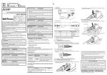
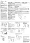
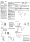
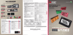
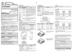
JY997D44201C Side B Side JAPANESE Side ENGLISH A B GT14-C10EXUSB-4S Panel-mounted USB Port Extension User's Manual Related Manuals 4. Installation The following manuals are relevant to this product. When these loose manuals are required please consult with our local distributor. 4.1 Installing panel-mounted USB port extension on panel surface Manual name Manual Number (Model Code) Contents GT14 User's Manual JY997D44801 (09R823) Describes the GT14 hardware-relevant content such as part names, external dimensions, mounting, wiring, specifications, and introduction to option devices. (sold separately) Install the panel-mounted USB port extension as shown below while paying attention to prevent bending and distortion of the cap, O-ring seal and nut. Panel thickness (2.0 (0.07") to 4.0 (0.15")) Insert securely the USB plug provided at the tip of the panel-mounted USB port extension into the USB port in the GOT. Fix the panel-mounted USB port extension itself to a structure inside the board or to the hole for preventing USB cable disconnection provided in the GOT main unit with a cable tie because the USB plug may become loose or come off due to vibration, impact or tensile force. Nut JY997D44201C Date April 2015 Bundled Items Bundled item Quantity GT14-C10EXUSB-4S panel-mounted USB port extension This manual describes the part names, installation, and specifications of the product. Before use, read this manual and manuals of relevant products fully to acquire proficiency in handling and operating the product. Make sure to learn all the product information, safety information, and precautions. And, store this manual in a safe place so that you can take it out and read it whenever necessary. Always forward it to the end user. Registration The company name and the product name to be described in this manual are the registered trademarks or trademarks of each company. Effective April 2015 Specifications are subject to change without notice. 2011 MITSUBISHI ELECTRIC CORPORATION In this manual, the safety precautions are ranked as 1 O-ring Seal 1 Nut 1 GT14-C10EXUSB-4S Panel-mounted USB Port Extension User’s Manual (This manual) 1 The panel-mounted USB port extension GT14-C10EXUSB-4S (hereinafter referred to as "panel-mounted USB port extension") is an extension cable having the waterproof function. Use this cable to pull the USB interface (host) provided on the back face of the GT14 to the control panel surface. The following GOT models support the panel-mounted USB port extension connection. GT1455-QTBD, GT1455-QTBDE, GT1450-QLBD, GT1450-QLBDE 2. Part Names and External Dimensions . 29 16 (1.14") (0.62") 1000 (39.37") Indicates that incorrect handling may cause hazardous conditions, resulting in death or severe injury. Indicates that incorrect handling may cause hazardous conditions, resulting in medium or slight personal injury or physical damage. may also be Ferrite core Mini USB plug Label model Cable O-ring Seal Nut Cap Use the panel-mounted USB port extension in the environment that satisfies the general specifications described in this manual. Not doing so can cause an electric shock, fire, malfunction or product damage or deterioration. When unplugging the panel-mounted USB port extension connected to the unit, do not hold and pull the cable portion. Doing so can cause the unit or cable to be damaged or can cause a malfunction due to a cable connection fault. DISPOSAL PRECAUTIONS When disposing of the product, handle it as industrial waste. Confirm at the start of work or during operation that this product is offering its function and performance normally, and then use this product. 19.4 0.1 (0.76" Panel cutting dimension 0) Unit: mm (inch) The panel thickness should be 2.0 (0.07”) to 4.0 (0.15”) mm. The panel-mounted USB port extension conforms to the protective structure IP67f on the panel surface equipped with the cap. The nut tightening torque is 0.294 to 0.343 N•m. Larger torque and smaller torque may deteriorate the waterproof effect. Tighten the cap securely while the panel-mounted USB port extension is not used. 5. Cautions on Installation of Panel-mounted USB Port Extension Run power lines, servo amplifier drive wires, and panel-mounted USB port extension so that they do not cross each other. Keep the panel-mounted USB port extension away from any equipment which can become noise source. Do not twist, bend at a sharp or right angle or pull the panel-mounted USB port extension. Such handling may cause wire breakage. Install the panel-mounted USB port extension under consideration of the dimensions inside the panel shown below. - Dimension between GOT rear face and structure Cap attached status MOUNTING PRECAUTIONS STARTUP/MAINTENANCE PRECAUTIONS Unit: mm (inch) 1. Overview GOT and Depending on circumstances, procedures indicated by linked to serious results. In any case, it is important to follow the directions for usage. 1 Cap Safety Precaution (Read these precautions before using.) Before using this product, please read this manual and the relevant manuals introduced in this manual carefully and pay full attention to safety to handle the product correctly. The precautions given in this manual are concerned with this product. Cap O-ring Seal 20.8 0.1 Manual Number This manual confers no industrial property rights or any rights of any other kind, nor does it confer any patent licenses. Mitsubishi Electric Corporation cannot be held responsible for any problems involving industrial property rights which may occur as a result of using the contents noted in this manual. Unit: mm (inch) 3. Specifications 80 (3.15") or more Warranty Mitsubishi will not be held liable for damage caused by factors found not to be the cause of Mitsubishi; opportunity loss or lost profits caused by faults in the Mitsubishi products; damage, secondary damage, accident compensation caused by special factors unpredictable by Mitsubishi; damages to products other than Mitsubishi products; and to other duties. 3.1 General Specifications Item Specifications Operating ambient temperature 0 to 55C Storage ambient temperature -20 to 60C Operating ambient humidity 10 to 90% RH, non-condensing (STN liquid crystal type to be stored at or below 39C WBT.) Storage ambient humidity 10 to 90% RH, non-condensing (STN liquid crystal type to be stored at or below 39C WBT.) Operating/Storage atmosphere Must be free of lamp black, corrosive gas, flammable gas, or excessive amount of electro conductive dust particles and must not be exposed to direct sunlight. (during operation and storage) Environmental protective structure Equivalent to IP67 (JEM1030) (front section) Unit: mm (inch) For safe use This product has been manufactured as a general-purpose part for general industries, and has not been designed or manufactured to be incorporated in a device or system used in purposes related to human life. Before using the product for special purposes such as nuclear power, electric power, aerospace, medicine or passenger movement vehicles, consult with Mitsubishi Electric. This product has been manufactured under strict quality control. However when installing the product where major accidents or losses could occur if the product fails, install appropriate backup or failsafe functions in the system. - Cable protrusion dimension 80 (3.15") or more Unit: mm (inch) HEAD OFFICE : TOKYO BUILDING, 2-7-3 MARUNOUCHI, CHIYODA-KU, TOKYO 100-8310, JAPAN