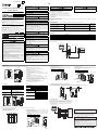
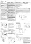
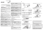
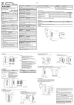
1
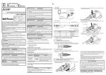
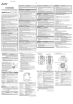
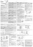
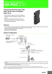
JY997D50901D Side B Side JAPANESE Side ENGLISH A B CONNECTOR CONVERSION BOX GT16H-CNB-37S User's Manual Manual Number JY997D50901D Date April 2015 DISPOSAL PRECAUTIONS Do not bundle the control and communication cables with main-circuit, power or other wiring. Run the above cables separately from such wiring and keep them a minimum of 100 mm (3.94 in.) apart. Not doing so noise can cause a malfunction. When disposing of the product, handle it as industrial waste. MOUNTING PRECAUTIONS Effective April 2015 Specifications are subject to change without notice. 2013 MITSUBISHI ELECTRIC CORPORATION Safety Precaution (Read these precautions before using.) Before using this product, please read this manual and the relevant manuals introduced in this manual carefully and pay full attention to safety to handle the product correctly. The precautions given in this manual are concerned with this product. In this manual, the safety precautions are ranked as and . Indicates that incorrect handling may cause hazardous conditions, resulting in death or severe injury. Indicates that incorrect handling may cause hazardous conditions, resulting in medium or slight personal injury or physical damage. Depending on circumstances, procedures indicated by linked to serious results. In any case, it is important to follow the directions for usage. may also be DESIGN PRECAUTIONS Some failures of the GOT or cable may keep the outputs on or off. An external monitoring circuit should be provided to check for output signals which may lead to a serious accident. Not doing so can cause an accident due to false output or malfunction. If a communication fault (including cable disconnection) occurs during monitoring on the GOT, communication between the GOT and PLC CPU is suspended and the GOT becomes inoperative. A system where the GOT is used should be configured to perform any significant operation to the system by using the switches of a device other than the GOT on the assumption that a GOT communication fault will occur. Not doing so can cause an accident due to false output or malfunction. Do not use the GOT as the warning device that may cause a serious accident. An independent and redundant hardware or mechanical interlock is required to configure the device that displays and outputs serious warning. Failure to observe this instruction may result in an accident due to incorrect output or malfunction. Incorrect operation of the touch switch(s) may lead to a serious accident if the GOT backlight is gone out. When the GOT backlight goes out, the POWER LED flickers (green/orange) and the display section turns black and causes the monitor screen to appear blank, while the input of the touch switch(s) remains active. This may confuse an operator in thinking that the GOT is in "screensaver" mode, who then tries to release the GOT from this mode by touching the display section, which may cause a touch switch to operate. Note that the following occurs on the GOT when the backlight goes out. - The POWER LED flickers (green/orange) and the monitor screen appears blank. Use the Connector Conversion Box within the generic environment specifications described in this manual. If the product is used in such conditions, electric shock, fire, malfunctions, deterioration or damage may occur. UL, cUL Standards are recognized in use by the following combination. GT14HANDY (GT1455HS-QTBDE series, GT1450HS-QMBDE series)*1 GT16H-CNB-37S External cable (GT11H-C30-37P, GT11H-C60-37P, GT11H-C100-37P)*2 Cable must be properly installed and routed to ensure protection of the Cable. *1 Version B or later *2 Version D or later General notes on power supply This equipment must be supplied by a UL Listed or Recognized 24 V dc rated power supply and UL Listed or Recognized fuse rated not higher than 4A, or a UL Listed Class 2 power supply. Associated Manuals WIRING PRECAUTIONS Be sure to shut off all phases of the external power supply used by the system before wiring. Failure to do so may result in an electric shock, product damage or malfunctions. Please make sure to ground FG terminal of the Connector Conversion Box power supply section by applying 100 or less which is used exclusively for the GOT. Not doing so may cause an electric shock or malfunction. Correctly wire the Connector Conversion Box power supply section after confirming the rated voltage and terminal arrangement of the GOT. Not doing so can cause a fire or failure. Exercise care to avoid foreign matter such as chips and wire offcuts entering the GOT. Not doing so can cause a fire, failure or malfunction. The following manuals are relevant to this product. When these loose manuals are required, please consult with our local distributor. Contents Manual Number (Model Code) GT16 Handy GOT User's Manual (Hardware/Utility, Connection) 1/2, 2/2 (sold separately) Describes the Handy GOT hardware-relevant content such as part names, external dimensions, mounting, power supply wiring, specifications, and introduction to option devices JY997D41201 JY997D41202 (09R821) GT14 Handy GOT User's Manual (Hardware/Utility, Connection) 1/2, 2/2 (sold separately) Describes the Handy GOT hardware-relevant content such as part names, external dimensions, mounting, power supply wiring, specifications, and introduction to option devices JY997D50201 JY997D50202 (09R825) Manual name For details of a PLC to be connected, refer to the PLC user's manual respectively. WIRING PRECAUTIONS Plug the communication cable into the connector of the connected unit and tighten the mounting and terminal screws in the specified torque range. Undertightening can cause a short circuit or malfunction. Overtightening can cause a short circuit or malfunction due to the damage of the screws or unit. TEST OPERATION PRECAUTIONS Before performing the test operations of the user creation monitor screen (such as turning ON or OFF bit device, changing the word device current value, changing the settings or current values of the timer or counter, and changing the buffer memory current value), read through the manual carefully and make yourself familiar with the operation method. During test operation, never change the data of the devices which are used to perform significant operation for the system. False output or malfunction can cause an accident. Bundled Items Bundled item Quantity Mounting fitting 1 Mounting screw (M38) 3 CONNECTOR CONVERSION BOX GT16H-CNB-37S User’s Manual (This manual) 1 1. Features The Connector Conversion Box relays the GOT's external D-Sub 37-pin connector to the power supply/switch and the PLC's connector and terminal block, while enabling users to operate the Handy GOT outside the enclosure. The connector conversion box does not support serial communication only in response to handy GOT and Ethernet communication between the PLC. Handy GOT (GT16 Handy, GT14 Handy) STARTUP/MAINTENANCE PRECAUTIONS Panel face To power supply switch When power is on, do not touch the terminals. Doing so can cause an electric shock or malfunction. Before starting cleaning or terminal screw retightening, always switch off the power externally in all phases. Not switching the power off in all phases can cause a unit failure or malfunction. Undertightening can cause a short circuit or malfunction. Overtightening can cause a short circuit or malfunction due to the damage of the screws or unit. PLC STARTUP/MAINTENANCE PRECAUTIONS External cable (option) Do not disassemble or modify the unit. Doing so can cause a failure, malfunction, injury or fire. Do not touch the conductive and electronic parts of the unit directly. Doing so can cause a unit malfunction or failure. The cables connected to the unit must be run in ducts or clamped. Not doing so can cause the unit or cable to be damaged due to the dangling, motion or accidental pulling of the cables or can cause a malfunction due to a cable connection fault. When unplugging the cable connected to the unit, do not hold and pull the cable portion. Doing so can cause the unit or cable to be damaged or can cause a malfunction due to a cable connection fault. 2. Part Name Relay cable Connector Conversion Box GT16H-CNB-37S 4.2 Mounting with a mounting bracket 3. Specifications Specifications Operating ambient temperature 0 to 55 C Operating ambient humidity 10 to 90 % RH, non-condensing Vibration resistance In conforms to JIS B3502 and IEC61131-2 5 to 8.4 Hz, Half-amplitude, 3.5 mm, 8.4 to 150 Hz, Acceleration 4.9 m/s2, 10 times sweeping in each of X, Y and Z directions Operating atmosphere Must be free of lamp black, corrosive gas, flammable gas, or excessive amount of electroconductive dust particles and must be no direct sunlight. (Same as for saving) Abbreviations GOT 1000 0.49 to 0.68 N•m Tightening torque 0.69 to 0.88 N•m Connector Conversion Box Mounting bracket (accessory) Drill 3-4.5 M4 screw and nut × 3 sets (prepared by user) Mounting screw (accessory) M3 screw × 3 pieces Mounting Bracket 10 (0.39") 20 (0.78") Unit: mm (inch) 4.3 Installation requirements for the rear face of enclosure Applicable GOTs Item Tightening torque 2) Mounting on the panel face Mount the Connector Conversion Box on the panel face. Drill screw holes on the panel face as follows. Tighten the mounting screw with the specified torque. Model name GT16 Handy GOT GT1665HS-VTBD GT14 Handy GOT GT1455HS-QTBDE, GT1450HS-QMBDE Make sure that interfering objects are not located within 100 mm (3.93”) from the rear face so that the connector of a PLC cable is not hindered. To wire the terminal block, keep a space of 25 mm (0.98”) or more on both sides of the Connector Conversion Box. 25 (0.98") 25 (0.98") Thread depth 6 (0.23") External cable which supports Handy GOT External cable GT16H-C30-37PE (3 m) GT16 Handy GOT GT16H-C60-37PE (6 m) GT16H-C100-37PE (10 m) GT11H-C30-37P*1 (3 m) 37.5 (1.47") GT14 Handy GOT Panel face GT11H-C60-37P*1 (6 m) 50 (1.96") General Specifications 1) Attaching a mounting bracket Attach the provided mounting bracket to the Connector Conversion Box. Tighten the mounting screw with the specified torque. 84 (3.3") 32(1.25") 32(1.25") The name and the function of each part of the Connector Conversion Box are described below. Front Panel Front Panel Back Panel 1) Connector for Handy GOT (D-Sub, 37-pin, female) 5) 2) Connects a Handy GOT through an external connection cable. 2) Power switch Supplies the power to the Handy GOT. When this switch is set to ON, the power is supplied. Turn off the power when attaching or detaching the Handy GOT. 3) Mounting hole (for M3 screw) 4) Allows to fix the Connector Conversion Box on the panel face directly or through a mounting bracket. 1) Back Panel 4) Terminal block for power supply and operation switches Connects the 24V DC power supply and operation switches (SW1 to SW6) of the Handy GOT. Terminal block for connection: M3 terminal screw, provided cover 5) Terminal block for emergency stop switch, grip switch, keylock switch Connects the emergency stop switch (ES-1, ES-2, ES-3), grip switch (DSW-1, 3) DSW-2), and keylock switch (KSW-1, KSW-2) Terminal block for connection: M3 terminal screw, provided cover 6) Connector for PLC (Ethernet: RJ-45 modular jack) Connects the PLC through a PLC cable. Base 6) External Dimensions 82 (3.22") The Connector Conversion Box is a precision instrument. During transportation, avoid impacts larger than those specified in this manual. Failure to do so may cause failures in the unit. After transportation, verify the operations of the unit. Certification of UL, cUL standards MOUNTING PRECAUTIONS Make sure to turn off the Connector Conversion Box's power before attaching or detaching it to/from the GOT. Failure to do so may cause unit failure or malfunctions. This manual describes the part names, dimensions, mounting, and specifications of the product. Before use, read this manual and manuals of relevant products fully to acquire proficiency in handling and operating the product. Make sure to learn all the product information, safety information, and precautions. And, store this manual in a safe place so that you can take it out and read it whenever necessary. Always forward it to the end user. Registration Ethernet is a trademark of Xerox Corporation in the United States.The company name and the product name to be described in this manual are the registered trademarks or trademarks of each company. TRANSPORTATION PRECAUTIONS DESIGN PRECAUTIONS Unit: mm (inch) *1 GT11H-C100-37P (10 m) 113 (4.44") *1 Use External cable version C or later. 5. Cautions for use For the emergency stop SW, the b contact type is used. When the Handy GOT is installed and removed with the connector, the switch changes ON to OFF when removed, which is the same as the state where the emergency switch is pressed. Design such as configuring a parallel circuit outside must be taken into consideration to avoid emergency stop while the Handy GOT is being removed. Handy GOT (GT16 Handy, GT14 Handy) Weight: about 0.2kg Unit : mm (inch) Panel face 4. Installation The Connector Conversion Box can be installed on the panel face directly or with mounting bracket offered as an accessory. ES-1 4.1 Direct mounting on the panel face 1) Direct mounting on the panel face Drill a mounting slot of the following size on the panel face. 18 (0.7") 28 (1.1") 18 (0.7") 25 (0.98") Drill 4-3.5 2) Mounting on the panel face Fit the Connector Conversion Box from the back side of the panel face, and fix it with four M3 screws (prepared by user). In the Connector Conversion Box, thread of M3, 6 mm (0.23”) in depth is cut in each mounting hole. Prepare four M3 mounting screws separately while considering the thickness of the panel face. Tighten the mounting screw with the specified torque. Tightening torque Panel cut area Unit: mm (inch) Panel face M3 screw × 4 pieces (prepared by user) Used as control signals of external device power ON/OFF ES-2 ES-2 ES-3 ES-3 Connector Conversion Box 91 (3.58") 60 (2.36") 0.49 to 0.68 N•m ES-1 Thread depth 6 (0.23") Connector Conversion Box Parallel circuit This manual confers no industrial property rights or any rights of any other kind, nor does it confer any patent licenses. Mitsubishi Electric Corporation cannot be held responsible for any problems involving industrial property rights which may occur as a result of using the contents noted in this manual. Warranty Mitsubishi will not be held liable for damage caused by factors found not to be the cause of Mitsubishi; opportunity loss or lost profits caused by faults in the Mitsubishi products; damage, secondary damage, accident compensation caused by special factors unpredictable by Mitsubishi; damages to products other than Mitsubishi products; and to other duties. For safe use This product has been manufactured as a general-purpose part for general industries, and has not been designed or manufactured to be incorporated in a device or system used in purposes related to human life. Before using the product for special purposes such as nuclear power, electric power, aerospace, medicine or passenger movement vehicles, consult with Mitsubishi Electric. This product has been manufactured under strict quality control. However when installing the product where major accidents or losses could occur if the product fails, install appropriate backup or failsafe functions in the system. Unit: mm (inch) HEAD OFFICE : TOKYO BUILDING, 2-7-3 MARUNOUCHI, CHIYODA-KU, TOKYO 100-8310, JAPAN JY997D50901D Side B Side JAPANESE Side ENGLISH A B CONNECTOR CONVERSION BOX GT16H-CNB-37S User's Manual Manual Number JY997D50901D Date April 2015 DISPOSAL PRECAUTIONS Do not bundle the control and communication cables with main-circuit, power or other wiring. Run the above cables separately from such wiring and keep them a minimum of 100 mm (3.94 in.) apart. Not doing so noise can cause a malfunction. When disposing of the product, handle it as industrial waste. MOUNTING PRECAUTIONS Effective April 2015 Specifications are subject to change without notice. 2013 MITSUBISHI ELECTRIC CORPORATION Safety Precaution (Read these precautions before using.) Before using this product, please read this manual and the relevant manuals introduced in this manual carefully and pay full attention to safety to handle the product correctly. The precautions given in this manual are concerned with this product. In this manual, the safety precautions are ranked as and . Indicates that incorrect handling may cause hazardous conditions, resulting in death or severe injury. Indicates that incorrect handling may cause hazardous conditions, resulting in medium or slight personal injury or physical damage. Depending on circumstances, procedures indicated by linked to serious results. In any case, it is important to follow the directions for usage. may also be DESIGN PRECAUTIONS Some failures of the GOT or cable may keep the outputs on or off. An external monitoring circuit should be provided to check for output signals which may lead to a serious accident. Not doing so can cause an accident due to false output or malfunction. If a communication fault (including cable disconnection) occurs during monitoring on the GOT, communication between the GOT and PLC CPU is suspended and the GOT becomes inoperative. A system where the GOT is used should be configured to perform any significant operation to the system by using the switches of a device other than the GOT on the assumption that a GOT communication fault will occur. Not doing so can cause an accident due to false output or malfunction. Do not use the GOT as the warning device that may cause a serious accident. An independent and redundant hardware or mechanical interlock is required to configure the device that displays and outputs serious warning. Failure to observe this instruction may result in an accident due to incorrect output or malfunction. Incorrect operation of the touch switch(s) may lead to a serious accident if the GOT backlight is gone out. When the GOT backlight goes out, the POWER LED flickers (green/orange) and the display section turns black and causes the monitor screen to appear blank, while the input of the touch switch(s) remains active. This may confuse an operator in thinking that the GOT is in "screensaver" mode, who then tries to release the GOT from this mode by touching the display section, which may cause a touch switch to operate. Note that the following occurs on the GOT when the backlight goes out. - The POWER LED flickers (green/orange) and the monitor screen appears blank. Use the Connector Conversion Box within the generic environment specifications described in this manual. If the product is used in such conditions, electric shock, fire, malfunctions, deterioration or damage may occur. UL, cUL Standards are recognized in use by the following combination. GT14HANDY (GT1455HS-QTBDE series, GT1450HS-QMBDE series)*1 GT16H-CNB-37S External cable (GT11H-C30-37P, GT11H-C60-37P, GT11H-C100-37P)*2 Cable must be properly installed and routed to ensure protection of the Cable. *1 Version B or later *2 Version D or later General notes on power supply This equipment must be supplied by a UL Listed or Recognized 24 V dc rated power supply and UL Listed or Recognized fuse rated not higher than 4A, or a UL Listed Class 2 power supply. Associated Manuals WIRING PRECAUTIONS Be sure to shut off all phases of the external power supply used by the system before wiring. Failure to do so may result in an electric shock, product damage or malfunctions. Please make sure to ground FG terminal of the Connector Conversion Box power supply section by applying 100 or less which is used exclusively for the GOT. Not doing so may cause an electric shock or malfunction. Correctly wire the Connector Conversion Box power supply section after confirming the rated voltage and terminal arrangement of the GOT. Not doing so can cause a fire or failure. Exercise care to avoid foreign matter such as chips and wire offcuts entering the GOT. Not doing so can cause a fire, failure or malfunction. The following manuals are relevant to this product. When these loose manuals are required, please consult with our local distributor. Contents Manual Number (Model Code) GT16 Handy GOT User's Manual (Hardware/Utility, Connection) 1/2, 2/2 (sold separately) Describes the Handy GOT hardware-relevant content such as part names, external dimensions, mounting, power supply wiring, specifications, and introduction to option devices JY997D41201 JY997D41202 (09R821) GT14 Handy GOT User's Manual (Hardware/Utility, Connection) 1/2, 2/2 (sold separately) Describes the Handy GOT hardware-relevant content such as part names, external dimensions, mounting, power supply wiring, specifications, and introduction to option devices JY997D50201 JY997D50202 (09R825) Manual name For details of a PLC to be connected, refer to the PLC user's manual respectively. WIRING PRECAUTIONS Plug the communication cable into the connector of the connected unit and tighten the mounting and terminal screws in the specified torque range. Undertightening can cause a short circuit or malfunction. Overtightening can cause a short circuit or malfunction due to the damage of the screws or unit. TEST OPERATION PRECAUTIONS Before performing the test operations of the user creation monitor screen (such as turning ON or OFF bit device, changing the word device current value, changing the settings or current values of the timer or counter, and changing the buffer memory current value), read through the manual carefully and make yourself familiar with the operation method. During test operation, never change the data of the devices which are used to perform significant operation for the system. False output or malfunction can cause an accident. Bundled Items Bundled item Quantity Mounting fitting 1 Mounting screw (M38) 3 CONNECTOR CONVERSION BOX GT16H-CNB-37S User’s Manual (This manual) 1 1. Features The Connector Conversion Box relays the GOT's external D-Sub 37-pin connector to the power supply/switch and the PLC's connector and terminal block, while enabling users to operate the Handy GOT outside the enclosure. The connector conversion box does not support serial communication only in response to handy GOT and Ethernet communication between the PLC. Handy GOT (GT16 Handy, GT14 Handy) STARTUP/MAINTENANCE PRECAUTIONS Panel face To power supply switch When power is on, do not touch the terminals. Doing so can cause an electric shock or malfunction. Before starting cleaning or terminal screw retightening, always switch off the power externally in all phases. Not switching the power off in all phases can cause a unit failure or malfunction. Undertightening can cause a short circuit or malfunction. Overtightening can cause a short circuit or malfunction due to the damage of the screws or unit. PLC STARTUP/MAINTENANCE PRECAUTIONS External cable (option) Do not disassemble or modify the unit. Doing so can cause a failure, malfunction, injury or fire. Do not touch the conductive and electronic parts of the unit directly. Doing so can cause a unit malfunction or failure. The cables connected to the unit must be run in ducts or clamped. Not doing so can cause the unit or cable to be damaged due to the dangling, motion or accidental pulling of the cables or can cause a malfunction due to a cable connection fault. When unplugging the cable connected to the unit, do not hold and pull the cable portion. Doing so can cause the unit or cable to be damaged or can cause a malfunction due to a cable connection fault. 2. Part Name Relay cable Connector Conversion Box GT16H-CNB-37S 4.2 Mounting with a mounting bracket 3. Specifications Specifications Operating ambient temperature 0 to 55 C Operating ambient humidity 10 to 90 % RH, non-condensing Vibration resistance In conforms to JIS B3502 and IEC61131-2 5 to 8.4 Hz, Half-amplitude, 3.5 mm, 8.4 to 150 Hz, Acceleration 4.9 m/s2, 10 times sweeping in each of X, Y and Z directions Operating atmosphere Must be free of lamp black, corrosive gas, flammable gas, or excessive amount of electroconductive dust particles and must be no direct sunlight. (Same as for saving) Abbreviations GOT 1000 0.49 to 0.68 N•m Tightening torque 0.69 to 0.88 N•m Connector Conversion Box Mounting bracket (accessory) Drill 3-4.5 M4 screw and nut × 3 sets (prepared by user) Mounting screw (accessory) M3 screw × 3 pieces Mounting Bracket 10 (0.39") 20 (0.78") Unit: mm (inch) 4.3 Installation requirements for the rear face of enclosure Applicable GOTs Item Tightening torque 2) Mounting on the panel face Mount the Connector Conversion Box on the panel face. Drill screw holes on the panel face as follows. Tighten the mounting screw with the specified torque. Model name GT16 Handy GOT GT1665HS-VTBD GT14 Handy GOT GT1455HS-QTBDE, GT1450HS-QMBDE Make sure that interfering objects are not located within 100 mm (3.93”) from the rear face so that the connector of a PLC cable is not hindered. To wire the terminal block, keep a space of 25 mm (0.98”) or more on both sides of the Connector Conversion Box. 25 (0.98") 25 (0.98") Thread depth 6 (0.23") External cable which supports Handy GOT External cable GT16H-C30-37PE (3 m) GT16 Handy GOT GT16H-C60-37PE (6 m) GT16H-C100-37PE (10 m) GT11H-C30-37P*1 (3 m) 37.5 (1.47") GT14 Handy GOT Panel face GT11H-C60-37P*1 (6 m) 50 (1.96") General Specifications 1) Attaching a mounting bracket Attach the provided mounting bracket to the Connector Conversion Box. Tighten the mounting screw with the specified torque. 84 (3.3") 32(1.25") 32(1.25") The name and the function of each part of the Connector Conversion Box are described below. Front Panel Front Panel Back Panel 1) Connector for Handy GOT (D-Sub, 37-pin, female) 5) 2) Connects a Handy GOT through an external connection cable. 2) Power switch Supplies the power to the Handy GOT. When this switch is set to ON, the power is supplied. Turn off the power when attaching or detaching the Handy GOT. 3) Mounting hole (for M3 screw) 4) Allows to fix the Connector Conversion Box on the panel face directly or through a mounting bracket. 1) Back Panel 4) Terminal block for power supply and operation switches Connects the 24V DC power supply and operation switches (SW1 to SW6) of the Handy GOT. Terminal block for connection: M3 terminal screw, provided cover 5) Terminal block for emergency stop switch, grip switch, keylock switch Connects the emergency stop switch (ES-1, ES-2, ES-3), grip switch (DSW-1, 3) DSW-2), and keylock switch (KSW-1, KSW-2) Terminal block for connection: M3 terminal screw, provided cover 6) Connector for PLC (Ethernet: RJ-45 modular jack) Connects the PLC through a PLC cable. Base 6) External Dimensions 82 (3.22") The Connector Conversion Box is a precision instrument. During transportation, avoid impacts larger than those specified in this manual. Failure to do so may cause failures in the unit. After transportation, verify the operations of the unit. Certification of UL, cUL standards MOUNTING PRECAUTIONS Make sure to turn off the Connector Conversion Box's power before attaching or detaching it to/from the GOT. Failure to do so may cause unit failure or malfunctions. This manual describes the part names, dimensions, mounting, and specifications of the product. Before use, read this manual and manuals of relevant products fully to acquire proficiency in handling and operating the product. Make sure to learn all the product information, safety information, and precautions. And, store this manual in a safe place so that you can take it out and read it whenever necessary. Always forward it to the end user. Registration Ethernet is a trademark of Xerox Corporation in the United States.The company name and the product name to be described in this manual are the registered trademarks or trademarks of each company. TRANSPORTATION PRECAUTIONS DESIGN PRECAUTIONS Unit: mm (inch) *1 GT11H-C100-37P (10 m) 113 (4.44") *1 Use External cable version C or later. 5. Cautions for use For the emergency stop SW, the b contact type is used. When the Handy GOT is installed and removed with the connector, the switch changes ON to OFF when removed, which is the same as the state where the emergency switch is pressed. Design such as configuring a parallel circuit outside must be taken into consideration to avoid emergency stop while the Handy GOT is being removed. Handy GOT (GT16 Handy, GT14 Handy) Weight: about 0.2kg Unit : mm (inch) Panel face 4. Installation The Connector Conversion Box can be installed on the panel face directly or with mounting bracket offered as an accessory. ES-1 4.1 Direct mounting on the panel face 1) Direct mounting on the panel face Drill a mounting slot of the following size on the panel face. 18 (0.7") 28 (1.1") 18 (0.7") 25 (0.98") Drill 4-3.5 2) Mounting on the panel face Fit the Connector Conversion Box from the back side of the panel face, and fix it with four M3 screws (prepared by user). In the Connector Conversion Box, thread of M3, 6 mm (0.23”) in depth is cut in each mounting hole. Prepare four M3 mounting screws separately while considering the thickness of the panel face. Tighten the mounting screw with the specified torque. Tightening torque Panel cut area Unit: mm (inch) Panel face M3 screw × 4 pieces (prepared by user) Used as control signals of external device power ON/OFF ES-2 ES-2 ES-3 ES-3 Connector Conversion Box 91 (3.58") 60 (2.36") 0.49 to 0.68 N•m ES-1 Thread depth 6 (0.23") Connector Conversion Box Parallel circuit This manual confers no industrial property rights or any rights of any other kind, nor does it confer any patent licenses. Mitsubishi Electric Corporation cannot be held responsible for any problems involving industrial property rights which may occur as a result of using the contents noted in this manual. Warranty Mitsubishi will not be held liable for damage caused by factors found not to be the cause of Mitsubishi; opportunity loss or lost profits caused by faults in the Mitsubishi products; damage, secondary damage, accident compensation caused by special factors unpredictable by Mitsubishi; damages to products other than Mitsubishi products; and to other duties. For safe use This product has been manufactured as a general-purpose part for general industries, and has not been designed or manufactured to be incorporated in a device or system used in purposes related to human life. Before using the product for special purposes such as nuclear power, electric power, aerospace, medicine or passenger movement vehicles, consult with Mitsubishi Electric. This product has been manufactured under strict quality control. However when installing the product where major accidents or losses could occur if the product fails, install appropriate backup or failsafe functions in the system. Unit: mm (inch) HEAD OFFICE : TOKYO BUILDING, 2-7-3 MARUNOUCHI, CHIYODA-KU, TOKYO 100-8310, JAPAN JY997D50901D Side B Side JAPANESE Side ENGLISH A B CONNECTOR CONVERSION BOX GT16H-CNB-37S User's Manual Manual Number JY997D50901D Date April 2015 DISPOSAL PRECAUTIONS Do not bundle the control and communication cables with main-circuit, power or other wiring. Run the above cables separately from such wiring and keep them a minimum of 100 mm (3.94 in.) apart. Not doing so noise can cause a malfunction. When disposing of the product, handle it as industrial waste. MOUNTING PRECAUTIONS Effective April 2015 Specifications are subject to change without notice. 2013 MITSUBISHI ELECTRIC CORPORATION Safety Precaution (Read these precautions before using.) Before using this product, please read this manual and the relevant manuals introduced in this manual carefully and pay full attention to safety to handle the product correctly. The precautions given in this manual are concerned with this product. In this manual, the safety precautions are ranked as and . Indicates that incorrect handling may cause hazardous conditions, resulting in death or severe injury. Indicates that incorrect handling may cause hazardous conditions, resulting in medium or slight personal injury or physical damage. Depending on circumstances, procedures indicated by linked to serious results. In any case, it is important to follow the directions for usage. may also be DESIGN PRECAUTIONS Some failures of the GOT or cable may keep the outputs on or off. An external monitoring circuit should be provided to check for output signals which may lead to a serious accident. Not doing so can cause an accident due to false output or malfunction. If a communication fault (including cable disconnection) occurs during monitoring on the GOT, communication between the GOT and PLC CPU is suspended and the GOT becomes inoperative. A system where the GOT is used should be configured to perform any significant operation to the system by using the switches of a device other than the GOT on the assumption that a GOT communication fault will occur. Not doing so can cause an accident due to false output or malfunction. Do not use the GOT as the warning device that may cause a serious accident. An independent and redundant hardware or mechanical interlock is required to configure the device that displays and outputs serious warning. Failure to observe this instruction may result in an accident due to incorrect output or malfunction. Incorrect operation of the touch switch(s) may lead to a serious accident if the GOT backlight is gone out. When the GOT backlight goes out, the POWER LED flickers (green/orange) and the display section turns black and causes the monitor screen to appear blank, while the input of the touch switch(s) remains active. This may confuse an operator in thinking that the GOT is in "screensaver" mode, who then tries to release the GOT from this mode by touching the display section, which may cause a touch switch to operate. Note that the following occurs on the GOT when the backlight goes out. - The POWER LED flickers (green/orange) and the monitor screen appears blank. Use the Connector Conversion Box within the generic environment specifications described in this manual. If the product is used in such conditions, electric shock, fire, malfunctions, deterioration or damage may occur. UL, cUL Standards are recognized in use by the following combination. GT14HANDY (GT1455HS-QTBDE series, GT1450HS-QMBDE series)*1 GT16H-CNB-37S External cable (GT11H-C30-37P, GT11H-C60-37P, GT11H-C100-37P)*2 Cable must be properly installed and routed to ensure protection of the Cable. *1 Version B or later *2 Version D or later General notes on power supply This equipment must be supplied by a UL Listed or Recognized 24 V dc rated power supply and UL Listed or Recognized fuse rated not higher than 4A, or a UL Listed Class 2 power supply. Associated Manuals WIRING PRECAUTIONS Be sure to shut off all phases of the external power supply used by the system before wiring. Failure to do so may result in an electric shock, product damage or malfunctions. Please make sure to ground FG terminal of the Connector Conversion Box power supply section by applying 100 or less which is used exclusively for the GOT. Not doing so may cause an electric shock or malfunction. Correctly wire the Connector Conversion Box power supply section after confirming the rated voltage and terminal arrangement of the GOT. Not doing so can cause a fire or failure. Exercise care to avoid foreign matter such as chips and wire offcuts entering the GOT. Not doing so can cause a fire, failure or malfunction. The following manuals are relevant to this product. When these loose manuals are required, please consult with our local distributor. Contents Manual Number (Model Code) GT16 Handy GOT User's Manual (Hardware/Utility, Connection) 1/2, 2/2 (sold separately) Describes the Handy GOT hardware-relevant content such as part names, external dimensions, mounting, power supply wiring, specifications, and introduction to option devices JY997D41201 JY997D41202 (09R821) GT14 Handy GOT User's Manual (Hardware/Utility, Connection) 1/2, 2/2 (sold separately) Describes the Handy GOT hardware-relevant content such as part names, external dimensions, mounting, power supply wiring, specifications, and introduction to option devices JY997D50201 JY997D50202 (09R825) Manual name For details of a PLC to be connected, refer to the PLC user's manual respectively. WIRING PRECAUTIONS Plug the communication cable into the connector of the connected unit and tighten the mounting and terminal screws in the specified torque range. Undertightening can cause a short circuit or malfunction. Overtightening can cause a short circuit or malfunction due to the damage of the screws or unit. TEST OPERATION PRECAUTIONS Before performing the test operations of the user creation monitor screen (such as turning ON or OFF bit device, changing the word device current value, changing the settings or current values of the timer or counter, and changing the buffer memory current value), read through the manual carefully and make yourself familiar with the operation method. During test operation, never change the data of the devices which are used to perform significant operation for the system. False output or malfunction can cause an accident. Bundled Items Bundled item Quantity Mounting fitting 1 Mounting screw (M38) 3 CONNECTOR CONVERSION BOX GT16H-CNB-37S User’s Manual (This manual) 1 1. Features The Connector Conversion Box relays the GOT's external D-Sub 37-pin connector to the power supply/switch and the PLC's connector and terminal block, while enabling users to operate the Handy GOT outside the enclosure. The connector conversion box does not support serial communication only in response to handy GOT and Ethernet communication between the PLC. Handy GOT (GT16 Handy, GT14 Handy) STARTUP/MAINTENANCE PRECAUTIONS Panel face To power supply switch When power is on, do not touch the terminals. Doing so can cause an electric shock or malfunction. Before starting cleaning or terminal screw retightening, always switch off the power externally in all phases. Not switching the power off in all phases can cause a unit failure or malfunction. Undertightening can cause a short circuit or malfunction. Overtightening can cause a short circuit or malfunction due to the damage of the screws or unit. PLC STARTUP/MAINTENANCE PRECAUTIONS External cable (option) Do not disassemble or modify the unit. Doing so can cause a failure, malfunction, injury or fire. Do not touch the conductive and electronic parts of the unit directly. Doing so can cause a unit malfunction or failure. The cables connected to the unit must be run in ducts or clamped. Not doing so can cause the unit or cable to be damaged due to the dangling, motion or accidental pulling of the cables or can cause a malfunction due to a cable connection fault. When unplugging the cable connected to the unit, do not hold and pull the cable portion. Doing so can cause the unit or cable to be damaged or can cause a malfunction due to a cable connection fault. 2. Part Name Relay cable Connector Conversion Box GT16H-CNB-37S 4.2 Mounting with a mounting bracket 3. Specifications Specifications Operating ambient temperature 0 to 55 C Operating ambient humidity 10 to 90 % RH, non-condensing Vibration resistance In conforms to JIS B3502 and IEC61131-2 5 to 8.4 Hz, Half-amplitude, 3.5 mm, 8.4 to 150 Hz, Acceleration 4.9 m/s2, 10 times sweeping in each of X, Y and Z directions Operating atmosphere Must be free of lamp black, corrosive gas, flammable gas, or excessive amount of electroconductive dust particles and must be no direct sunlight. (Same as for saving) Abbreviations GOT 1000 0.49 to 0.68 N•m Tightening torque 0.69 to 0.88 N•m Connector Conversion Box Mounting bracket (accessory) Drill 3-4.5 M4 screw and nut × 3 sets (prepared by user) Mounting screw (accessory) M3 screw × 3 pieces Mounting Bracket 10 (0.39") 20 (0.78") Unit: mm (inch) 4.3 Installation requirements for the rear face of enclosure Applicable GOTs Item Tightening torque 2) Mounting on the panel face Mount the Connector Conversion Box on the panel face. Drill screw holes on the panel face as follows. Tighten the mounting screw with the specified torque. Model name GT16 Handy GOT GT1665HS-VTBD GT14 Handy GOT GT1455HS-QTBDE, GT1450HS-QMBDE Make sure that interfering objects are not located within 100 mm (3.93”) from the rear face so that the connector of a PLC cable is not hindered. To wire the terminal block, keep a space of 25 mm (0.98”) or more on both sides of the Connector Conversion Box. 25 (0.98") 25 (0.98") Thread depth 6 (0.23") External cable which supports Handy GOT External cable GT16H-C30-37PE (3 m) GT16 Handy GOT GT16H-C60-37PE (6 m) GT16H-C100-37PE (10 m) GT11H-C30-37P*1 (3 m) 37.5 (1.47") GT14 Handy GOT Panel face GT11H-C60-37P*1 (6 m) 50 (1.96") General Specifications 1) Attaching a mounting bracket Attach the provided mounting bracket to the Connector Conversion Box. Tighten the mounting screw with the specified torque. 84 (3.3") 32(1.25") 32(1.25") The name and the function of each part of the Connector Conversion Box are described below. Front Panel Front Panel Back Panel 1) Connector for Handy GOT (D-Sub, 37-pin, female) 5) 2) Connects a Handy GOT through an external connection cable. 2) Power switch Supplies the power to the Handy GOT. When this switch is set to ON, the power is supplied. Turn off the power when attaching or detaching the Handy GOT. 3) Mounting hole (for M3 screw) 4) Allows to fix the Connector Conversion Box on the panel face directly or through a mounting bracket. 1) Back Panel 4) Terminal block for power supply and operation switches Connects the 24V DC power supply and operation switches (SW1 to SW6) of the Handy GOT. Terminal block for connection: M3 terminal screw, provided cover 5) Terminal block for emergency stop switch, grip switch, keylock switch Connects the emergency stop switch (ES-1, ES-2, ES-3), grip switch (DSW-1, 3) DSW-2), and keylock switch (KSW-1, KSW-2) Terminal block for connection: M3 terminal screw, provided cover 6) Connector for PLC (Ethernet: RJ-45 modular jack) Connects the PLC through a PLC cable. Base 6) External Dimensions 82 (3.22") The Connector Conversion Box is a precision instrument. During transportation, avoid impacts larger than those specified in this manual. Failure to do so may cause failures in the unit. After transportation, verify the operations of the unit. Certification of UL, cUL standards MOUNTING PRECAUTIONS Make sure to turn off the Connector Conversion Box's power before attaching or detaching it to/from the GOT. Failure to do so may cause unit failure or malfunctions. This manual describes the part names, dimensions, mounting, and specifications of the product. Before use, read this manual and manuals of relevant products fully to acquire proficiency in handling and operating the product. Make sure to learn all the product information, safety information, and precautions. And, store this manual in a safe place so that you can take it out and read it whenever necessary. Always forward it to the end user. Registration Ethernet is a trademark of Xerox Corporation in the United States.The company name and the product name to be described in this manual are the registered trademarks or trademarks of each company. TRANSPORTATION PRECAUTIONS DESIGN PRECAUTIONS Unit: mm (inch) *1 GT11H-C100-37P (10 m) 113 (4.44") *1 Use External cable version C or later. 5. Cautions for use For the emergency stop SW, the b contact type is used. When the Handy GOT is installed and removed with the connector, the switch changes ON to OFF when removed, which is the same as the state where the emergency switch is pressed. Design such as configuring a parallel circuit outside must be taken into consideration to avoid emergency stop while the Handy GOT is being removed. Handy GOT (GT16 Handy, GT14 Handy) Weight: about 0.2kg Unit : mm (inch) Panel face 4. Installation The Connector Conversion Box can be installed on the panel face directly or with mounting bracket offered as an accessory. ES-1 4.1 Direct mounting on the panel face 1) Direct mounting on the panel face Drill a mounting slot of the following size on the panel face. 18 (0.7") 28 (1.1") 18 (0.7") 25 (0.98") Drill 4-3.5 2) Mounting on the panel face Fit the Connector Conversion Box from the back side of the panel face, and fix it with four M3 screws (prepared by user). In the Connector Conversion Box, thread of M3, 6 mm (0.23”) in depth is cut in each mounting hole. Prepare four M3 mounting screws separately while considering the thickness of the panel face. Tighten the mounting screw with the specified torque. Tightening torque Panel cut area Unit: mm (inch) Panel face M3 screw × 4 pieces (prepared by user) Used as control signals of external device power ON/OFF ES-2 ES-2 ES-3 ES-3 Connector Conversion Box 91 (3.58") 60 (2.36") 0.49 to 0.68 N•m ES-1 Thread depth 6 (0.23") Connector Conversion Box Parallel circuit This manual confers no industrial property rights or any rights of any other kind, nor does it confer any patent licenses. Mitsubishi Electric Corporation cannot be held responsible for any problems involving industrial property rights which may occur as a result of using the contents noted in this manual. Warranty Mitsubishi will not be held liable for damage caused by factors found not to be the cause of Mitsubishi; opportunity loss or lost profits caused by faults in the Mitsubishi products; damage, secondary damage, accident compensation caused by special factors unpredictable by Mitsubishi; damages to products other than Mitsubishi products; and to other duties. For safe use This product has been manufactured as a general-purpose part for general industries, and has not been designed or manufactured to be incorporated in a device or system used in purposes related to human life. Before using the product for special purposes such as nuclear power, electric power, aerospace, medicine or passenger movement vehicles, consult with Mitsubishi Electric. This product has been manufactured under strict quality control. However when installing the product where major accidents or losses could occur if the product fails, install appropriate backup or failsafe functions in the system. Unit: mm (inch) HEAD OFFICE : TOKYO BUILDING, 2-7-3 MARUNOUCHI, CHIYODA-KU, TOKYO 100-8310, JAPAN