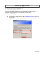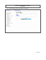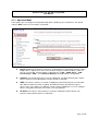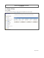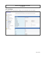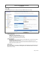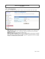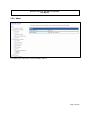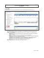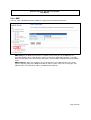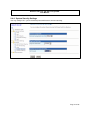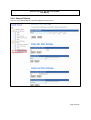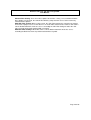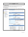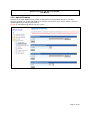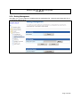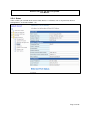
1
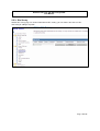
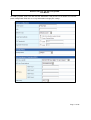
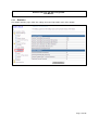
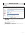
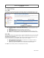
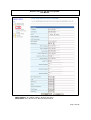
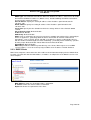
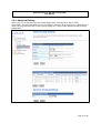
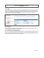
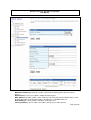
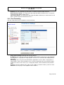
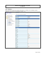
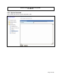
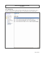
802.11a/n and 802.11a/b/g/n
Wireless CPE
User Manual
Wireless 802.11a/n and 802.11a/b/g/n CPE
User Manual
NOTICE
Changes or modifications to the equipment, which are not approved by the party responsible for
compliance, could affect the user's authority to operate the equipment. Company has an on-going policy
of upgrading its products and it may be possible that information in this document is not up-to-date.
Please check with your local distributors for the latest information.
COPYRIGHT
2009 All Rights Reserved.
No part of this document can be copied or reproduced in any form without written consent from the
company.
Trademarks:
All trade names and trademarks are the properties of their respective companies.
REVISION HISTORY
Rev.
0.1
Changes
Initial release
Date
August 28, 2009
Page 2 of 36
Wireless 802.11a/n and 802.11a/b/g/n CPE
User Manual
1. GETTING START
The WLAN Broadband CPE is delivered with the following factory default parameters on the Ethernet LAN
interfaces.
Default IP Address: 10.10.10.254
Default IP subnet mask: 255.255.255.0
WEB login User Name: admin
WEB login Password: admin
The device has four operation modes (Bridge /Gateway/WISP /AP Client). The default IP addresses for the
device are 10.10.10.254, so you need to make sure the IP address of your PC is in the same subnet as the
device, such as 10.10.10.X.
It will take about 25 seconds to complete the boot up sequence after power on.
Prepare your PC to configure the WLAN Broadband CPE
For OS of Microsoft Windows 95/ 98/ Me:
1. Click the Start button and select Settings, then click Control Panel. The Control Panel
window will appear.
Note: Windows Me users may not see the Network control panel. If so, select View all
Control Panel options on the left side of the window.
2. Move mouse and double-click the right button on Network icon. The Network window will
appear.
3. Check the installed list of Network Components. If TCP/IP is not installed, click the Add
button to install it; otherwise go to step 6.
4. Select Protocol in the Network Component Type dialog box and click Add button
5. Select TCP/IP in Microsoft of Select Network Protocol dialog box then click OK button
to install the TCP/IP protocol, it may need the Microsoft Windows CD to complete the
installation. Close and go back to Network dialog box after the TCP/IP installation.
6. Select TCP/IP and click the properties button on the Network dialog box.
7. Select Specify an IP address and type in values as following example.
IP Address: 10.10.10.1, (any IP address within 10.10.10.1 to 10.10.10.253 is good
to connect the Wireless LAN Access Point).
IP Subnet Mask: 255.255.255.0
8. Click OK and reboot your PC after completes the IP parameters setting
For OS of Microsoft Windows 2000, XP:
1. Click the Start button and select Settings, then click Control Panel. The Control Panel
window will appear.
2. Move mouse and double-click the right button on Network and Dial-up Connections
icon. Move mouse and double-click the Local Area Connection icon. The Local Area
Connection window will appear. Click Properties button in the Local Area Connection
window
3. Check the installed list of Network Components. If TCP/IP is not installed, click the Add
button to install it; otherwise go to step 6.
4. Select Protocol in the Network Component Type dialog box and click Add button.
Page 3 of 36
Wireless 802.11a/n and 802.11a/b/g/n CPE
User Manual
5.
6.
7.
8.
Select TCP/IP in Microsoft of Select Network Protocol dialog box then click OK button
to install the TCP/IP protocol, it may need the Microsoft Windows CD to complete the
installation. Close and go back to Network dialog box after the TCP/IP installation.
Select TCP/IP and click the properties button on the Network dialog box.
Select Specify an IP address and type in values as following example.
IP Address: 10.10.10.1, (any IP address within 10.10.10.1 to 10.10.10.253 is good
to connect the Wireless LAN Access Point).
IP Subnet Mask: 255.255.255.0.
Click OK to complete the IP parameters setting.
For OS of Microsoft Windows NT:
1. Click the Start button and select Settings, then click Control Panel. The Control Panel
window will appear.
2. Move mouse and double-click the right button on Network icon. The Network window will
appear. Click Protocol tab from the Network window.
3. Check the installed list of Network Protocol window. If TCP/IP is not installed, click the
Add button to install it; otherwise go to step 6.
4. Select Protocol in the Network Component Type dialog box and click Add button.
5. Select TCP/IP in Microsoft of Select Network Protocol dialog box then click OK button
to install the TCP/IP protocol, it may need the Microsoft Windows CD to complete the
installation. Close and go back to Network dialog box after the TCP/IP installation.
6. Select TCP/IP and click the properties button on the Network dialog box.
7. Select Specify an IP address and type in values as following example.
IP Address: 10.10.10.1, any IP address within 10.10.10.1 to 10.10.10.253 is good to
connect the Wireless LAN Access Point.
IP Subnet Mask: 255.255.255.0
8. Click OK to complete the IP parameters setting
For OS of Microsoft Windows Vista and Windows 7
1.
Click Start Button and select Control Panel, the Control Panel windows pop up.
2.
From Network and Internet category choose View network status and tasks.
3.
Select Change adapter settings, right click Local Area Connection, select Properties
4.
From popup menu in Networking tab select Internet Protocol Version 4 (TCP/IPv4) then click
Properties.
5.
Check Use the following IP address then Specify IP address as following example.
Enter your IP Address; the IP Address can be any number within the range from 10.10.10.1
to 10.10.10.253.
IP Subnet Mask: 255.255.255.0
Click OK to complete the IP parameters setting.
Page 4 of 36
Wireless 802.11a/n and 802.11a/b/g/n CPE
User Manual
2. CONFIGURATION OF WEB UTILITY
The Wireless CPE implements a Web utility allowing user to manage the operation via a user friendly
interface. This Utility provides comprehensive system management scheme, including system
configuration, performance monitoring, system maintenance and administration.
2.1. Access Web Utility
To access the Web Utility, you have to launch your Internet Browser. (i.e., MS. IE 5.0 or later, Netscape
Navigator 4.7 or later).
Step1: Enter Wireless Router’s default IP address as http://10.10.10.254 in the Address field
then press Enter.
Step2: Login dialog box will appear, enter admin as Administrator Name and admin as
default administrator password, and then click “Login” to access configuration utility.
-
Page 5 of 36
Wireless 802.11a/n and 802.11a/b/g/n CPE
User Manual
Step3: After log in, you can see the Main menu as below.
Page 6 of 36
Wireless 802.11a/n and 802.11a/b/g/n CPE
User Manual
2.1.1. Operation Mode
In this option, you can configure the operation mode which suitable for your environment. The default
setting is WISP. There have four modes is provided:
Bridge: All Ethernet and wireless interfaces are bridged into a single bridge interface. When
Bridge mode is applied, there have some functions change in Internet Settings section. As
you can see in below, Internet Settings section only has “LAN”, “DHCP Client”, “VPN
Pass-through”, “DNS”, and “Advanced Routing” for Bridge Mode’s configuration.
Gateway: The first Ethernet port is treated as WAN port. The other Ethernet ports and the
wireless interface are bridge together and are treated as LAN ports.
WISP: The wireless interface is treated as WAN port and the Ethernet ports are LAN ports.
After Ethernet Converter mode is applied, the WAN will change from Ethernet type to
wireless type. There will be five LAN ports and one wireless WAN port. User must configure
wireless encryption connection and set the necessary protocols.
AP Client: The wireless client interface is treated as WAN port, and the wireless AP
interface and the Ethernet ports are LAN ports.
Page 7 of 36
Wireless 802.11a/n and 802.11a/b/g/n CPE
User Manual
2.2. Wireless Settings
2.2.1. Profile
The Station Profile page shows the settings and current operation status of the station.
Page 8 of 36
Wireless 802.11a/n and 802.11a/b/g/n CPE
User Manual
2.2.2. Link Status
The Station Link Status page shows the settings and current operation status of the Station.
Page 9 of 36
Wireless 802.11a/n and 802.11a/b/g/n CPE
User Manual
2.2.3. Site Survey
Station Site Survey page can shows information of APs nearby, you can choose one of these APs
connecting or adding it to profile.
Page 10 of 36
Wireless 802.11a/n and 802.11a/b/g/n CPE
User Manual
For adding a profile, choose one AP and click “Add Profile”. And you will see the below screen for AP
profile configuration. Enter the necessary information and apply the settings.
Page 11 of 36
Wireless 802.11a/n and 802.11a/b/g/n CPE
User Manual
2.2.4.
Statistics
The Station Statistics page shows the settings and current operation status of the Station.
Page 12 of 36
Wireless 802.11a/n and 802.11a/b/g/n CPE
User Manual
2.2.5. Advance
The Station Advanced Configuration page shows the settings and current operation status of the station.
Wireless Mode: Select wireless mode. 802.11A Only, 802.11 AN mix mode are supported.
Country Region Code: This field displays the region of operation for which the wireless
interface is intended.
B/G Protection: User can choose from Auto, On, and Off
Auto: STA will dynamically change as AP announcement
ON: Always send frame with protection.
Off: Always send frame without protection.
TX Rate: Manually force the Transmit using selected rate. Default is auto.
TX Burst: Frame burst mode.
HT Physical Mode: Configure HT Status in use, containing HT(MM or GF), BW(20 or Auto),
GI(Long or Auto), and MCS(0~15, 32, or Auto) settings.
Page 13 of 36
Wireless 802.11a/n and 802.11a/b/g/n CPE
User Manual
2.2.6. QoS
The QoS configuration page can allow you to configure WMM and Direct Link settings
(1) QoS Configuration
WMM: Enable Wi-Fi Multi-Media.
WMM Power Saving: Enable WMM Power Save.
PS Mode: Select which ACs you want to enable.
Direct Link Setup: Enable DLS (direct Link Setup).
(2) Direct Link Setup
MAC Address: Fill in the blanks of Direct Link with MAC address of STA. Connect with the
same AP that supports DLS features
Timeout Value: Timeout Value represent that it disconnect automatically after some
seconds. The value is integer. The integer must be between 0~65535. It represents that it
always connects if the value is zero.
(3) DLS Status
After configuring DLS successfully, show MAC address of the opposite side and Timeout Value of
setting in “DLS Status”. In “DLS Status” of the opposite side, it shows MAC address of itself and
Timeout Value of setting.
Page 14 of 36
Wireless 802.11a/n and 802.11a/b/g/n CPE
User Manual
2.2.7. 11n Configurations
The Station 11n Configurations page shows the settings and current operation status of the station.
MPDU Aggregation: MPDU stands for MAC Protocol Data Unit. MPDUs are the fragmented units
of MSDU, also called MAC frames, encapsulate the higher layer protocol data or contain MAC
management messages.
MPDU Density: Select 0~7 to configure the MPDU density.
Aggregation MDSU (A-MSDU): A-MSDU stands for Aggregate MAC service data unit. This option
allows aggregation of multiple MSDU in one MPDU. The MSDU is that unit of data that is received
from the LLC sub-layer which lies above the MAC sub-layer in a protocol stack. The LLC and MAC
sub-layers are collectively referred to as the DLL.
Page 15 of 36
Wireless 802.11a/n and 802.11a/b/g/n CPE
User Manual
2.2.8. About
The About page shows driver version and MAC address.
Page 16 of 36
Wireless 802.11a/n and 802.11a/b/g/n CPE
User Manual
2.2.9. WPS
You can setup security easily by choosing PIN or PBC method to do Wi-Fi Protected setup.
WPS AP Site Survey: Display the information of surrounding APs with WPS IE from last scan
result. List information includes SSID, BSSID, RSSI, Channel, ID (Device Password ID), Auth.,
Encrypt, Ver., and Status.
Refresh: Issue a rescan command to wireless NIC to update information on surrounding
wireless network.
Mode: Our station role-playing as an Enrollee or an external Registrar.
PIN: 8-digit numbers. It is required to enter PIN Code into Registrar using PIN method. Each
NIC Wireless has only one PIN Code of Enrollee.
PIN Start: Start to add to Registrar using PIN configuration method. IF STA Registrar,
remember that enter PIN Code read from you Enrollee before starting PIN.
PBC Start: Start to add to AP using PBC configuration method.
WPS Status: Display the current status of the WPS function.
Page 17 of 36
Wireless 802.11a/n and 802.11a/b/g/n CPE
User Manual
2.3. Internet Settings
2.3.1. WAN
The WAN port is the connection of the 802.11n AP Router module to existing broadband device such as
Cable modem or ADSL CPE. Click WAN on Internet Setting, below screen will prompt for WAN setting.
This AP Router supports 5 methods of obtaining the WAN IP Address:
Static IP (fixed IP): Use static IP address to access Network. Your ISP will provide a static
IP address.
DHCP (Auto Config): Automatic gets IP address from your ISP.
PPPoE (ADSL): PPPoE is a common connection type used for xDSL.
PPTP: PPP Tunneling Protocol can support multi-protocol Virtual Private Network (VPN).
L2TP: Layer 2 Tunneling Protocol can support multi-protocol Virtual Private Networks (VPN)
2.3.2. LAN
When the module operates in the Gateway mode, it supports the NAT (NAPT) feature. It means the WAN
and LAN interfaces are located in different network segments and therefore the date traffic needs to be
routed between the two interfaces.
To communicate with 802.11n router properly, must assign an IP address to the LAN port of the user’s
PC. There are two ways to assign a proper IP address to the user PC’s LAN port:
Manual configuration of the user PC: This required if the user configures the 802.11n
router WAN port with a static IP address.
Dynamic IP assignment with DHCP: 802.11n router can act as a DHCP server which
dynamically assigns an IP address to user’s PC located in the LAN-side network.
Click LAN on Internet Settings, below screen will prompt for LAN setting.
Page 18 of 36
Wireless 802.11a/n and 802.11a/b/g/n CPE
User Manual
LAN IP Address: The LAN IP address. Default: 192.168.1.1
Subnet Mask: The LAN net-mask. Default: 255.255.255.0
Page 19 of 36
Wireless 802.11a/n and 802.11a/b/g/n CPE
User Manual
DHCP Type: Select Disable to disable this Router to distribute IP address. Select Server to enable
this Router to distribute IP addresses (DHCP server). And the following field will be activated for
you to enter this starting IP address.
Start IP address: Specify the starting IP address of the IP address pool. Default Start IP:
192.168.1.100.
End IP address: Specify the ending IP address of the IP address pool. Default End IP:
192.168.1.250.
Lease Time: Specify the time duration for which the settings will be in effect. Default: 86400
seconds.
802.1d Spanning Tree: Default: Disable.
LLTD: Default: Disable.
IGMP Proxy: Default: Disable.
UPnP: UPuP is architecture for pervasive peer-to-peer network connectivity of PCs and intelligent
devices or appliances, particularly within the home. UPnP builds on Internet standards and
technologies, such as TCP/IP, HTTP, and XML, to enable these devices automatically connect
with one another and work together to make networking – particularly home networking – possible
for more people. Default: Disable. Router Advertisement: Default: Disable.
PPPoE Relay: Default: Disable.
DNS Proxy: Enable the DNS Proxy that will relay users’/clients’ DNS requests to a real DNS
server IP address. Users no need to specify real DNS server IP address. Default: Enabled.
2.3.3. DHCP Clients
DHCP client computers connected to the device will have their information displayed in the DHCP Client
List table. The table will show the MAC Address, IP Address and Expired in of the DHCP lease for each
client computer.
MAC Address: Shows the client MAC address information.
IP address: Shows the client IP address information.
Expires in: Shows the expired time of the client.
Page 20 of 36
Wireless 802.11a/n and 802.11a/b/g/n CPE
User Manual
2.3.4. Advanced Routing
Static routes are special routes that the network administrator manually enters into the router
configuration. The route table allows the user to configure and define all the static routes supported by the
router. You may add and remote custom Internet routing rules, and/or enable dynamic routing exchange
protocol here.
Page 21 of 36
Wireless 802.11a/n and 802.11a/b/g/n CPE
User Manual
[Add a routing rule]
Destination: Defines the base IP address (Network Number) that will be compared with the
destination IP address (after an AND with NetMask) to see if this is the target route.
Range: select the range from drop down list
Gateway: Enter IP address of the next hop router that will be used to route traffic for this route If
this route is local (defines the locally connected hosts and Type = Host) then this IP address
MUST be the IP Address of the router.
Interface: Select the interface mode from drop down list.
Comment: Enter the comment for this static route.
[Current Routing table in the system]
To see the detail settings of current routing table in the system.
[Dynamic Routing Setting]
RIP: RIP can be used to cache routes learned by routing protocols, thus allowing the automation
of static routing maintenance. The router, using the RIP (Routing Information Protocol) protocol,
determines the network packet’s route based on the fewest number of hops between the source
and the destination. In this case, you could automatically adjust to physical changes in the
network layout. Default is Disable.
Page 22 of 36
Wireless 802.11a/n and 802.11a/b/g/n CPE
User Manual
2.3.5. QoS
QoS (Quality of Service) is a different priority bandwidth control; this function could help to separate the
packet to different priority to WAN connection. This option will provide better service of selected network
traffic over various technologies. Deploying QoS management to guarantee that all application receive the
service levels required and sufficient bandwidth to meet performance expectations is indeed one
important aspect of modem enterprise network.
2.4. Firewall
The Firewall contains the following sections: MAC/IP/Port Filtering, Port Forwarding, DMZ, System
Security Setting, Content Filtering, and Port Trigger
2.4.1. MAC/IP/Port Filtering Settings
You can setup firewall rules to protect your network from virus, worm and malicious activity on the internet.
Filters are used to deny or allow LAN computers from access the Internet. Within the local area network,
the unit can be setup to deny Internet access to computers using the assigned IP or MAC addresses. The
unit can also block users from accessing restricted web site.
Page 23 of 36
Wireless 802.11a/n and 802.11a/b/g/n CPE
User Manual
MAC/IP/Port Filtering: Enable this function, all list from the filtering will be deny the internet
access.
Default Policy: There have 2 options, Dropped and Accepted.
MAC Address: The MAC address of the computer in the LAN (Local Area Network) to be used in
the MAC filter table. Enter the MAC address of LAN port, e.g. 00:00:27:88:81:18
Dest IP Address: The IP address that will be denied to access.
Source IP Address: The IP address that will be denied access to the Internet.
Page 24 of 36
Wireless 802.11a/n and 802.11a/b/g/n CPE
User Manual
Protocol: This is the protocol type that will be used with the Port that will be blocked.
Destination Port Range: The single port or port range that will be denied to access. If no port is
specified, all ports will be denied access.
Source Port Range: The single port or port range that will be denied access to the Internet. If no
port is specified, all ports will be denied access.
2.4.2. Port Forwarding
You may setup virtual servers to provide service on internet.
Virtual Server Setting: Enable/Disable the port forward.
IP Address: This is the port number on the WAN side that will be used to access the application.
You may define a single port or a range of ports. You can use a comma to add multiple ports or
port ranges.
Port Range: This is the port used to forward the application. It can be either a single port or a
range of ports. For the TCP and UDP services enter the beginning of the range of port numbers
used by the service. If the service uses a single port number, enter it in both the start and finish
fields.
Protocol: Select the protocol (TCP, UDP, or TCP & UDP) used to the remote system or service.
Comment: You may key in a description for the IP address.
Page 25 of 36
Wireless 802.11a/n and 802.11a/b/g/n CPE
User Manual
2.4.3. DMZ
You may setup a De-Militarized Zone (DMZ) to separate internet network and internet.
DMZ Setting: If the DMZ Host Function is enabled, it means that you set up DMZ host at a
particular computer to be exposed to the Internet so that some applications/software, especially
Internet/Online game can have two-way connections. Select Enable or Disable from the pull-down
menu.
DMZ IP Address: Enter the IP address of a particular host in your LAN that will receive all the
packets originally going to the WAN port/Public IP address above. Note: You need to give your
LAN PC clients a fixed/static IP address for DMZ to work properly.
Page 26 of 36
Wireless 802.11a/n and 802.11a/b/g/n CPE
User Manual
2.4.4. System Security Settings
You may configure the system firewall to protect AP/Router itself from attacking.
Page 27 of 36
Wireless 802.11a/n and 802.11a/b/g/n CPE
User Manual
2.4.5. Content Filtering
You can setup content filter to restrict the improper content access.
Page 28 of 36
Wireless 802.11a/n and 802.11a/b/g/n CPE
User Manual
Content Filter Setting: There have three options for this filter – Proxy, Java, and ActiveX.When
those options are checked, the content filter will deny computer from access to the internet by
contented those options.
Web URL Filter Setting: With security reason, the URL Filter provides the enterprise to manage
and restrict employee access to non-business or undesirable content on the Internet. URL Filter is
a web solution that blocks web-sites access according the URL Filter String no matter the URL
string is found full or partial matched with a keyword.
Web Host Filter Settings: Web Host Filter is a web solution that blocks web-sites access
according the Web Host name or partial matched with a keyword.
Page 29 of 36
Wireless 802.11a/n and 802.11a/b/g/n CPE
User Manual
2.5. Administration
The Administration contains the following sections: Administration, Upload Firmware, Setting
Management, Status, Statistics, System Command, and System Log
2.5.1. Management
You may configure administrator account and password, NTP settings, and Dynamic DNS settings here.
Page 30 of 36
Wireless 802.11a/n and 802.11a/b/g/n CPE
User Manual
2.5.2. Upload Firmware
Firmware is the main software image, which the AP Router needs to perform all tasks in real time.
Firmware upgrades are required for adding new features or to resolves bugs. It takes about 1 minute to
upload/upgrade flash and be patient please.
Caution: A corrupted image will hang up the system.
Page 31 of 36
Wireless 802.11a/n and 802.11a/b/g/n CPE
User Manual
2.5.3. Setting Management
You might save system settings by exporting them to configuration file, restore them by import the file, or
reset them to factory default.
Page 32 of 36
Wireless 802.11a/n and 802.11a/b/g/n CPE
User Manual
2.5.4. Status
In this section, you can look at the status of this wireless 11n Router, such as System Info, Internet
Configurations, and Local Network…etc.
Page 33 of 36
Wireless 802.11a/n and 802.11a/b/g/n CPE
User Manual
2.5.5. Statistics
In this section, you can look at the statistics of this wireless 11n Router, such as Memory statistics,
WAN/LAN’s Rx & Tx packets, and all interface statistics…etc
Page 34 of 36
Wireless 802.11a/n and 802.11a/b/g/n CPE
User Manual
2.5.6. System Command
In this section, you can run a system command as root.
Page 35 of 36
Wireless 802.11a/n and 802.11a/b/g/n CPE
User Manual
2.5.7. System Log
This 802.11n Router supports sending system log (sending UDP packets and keeping log messages in
Log Server. Click Refresh on Administration, below screen will prompt for System Log information
Page 36 of 36