1
User’s Manual
(For SI/ engineer)
Powerline/Cable
200M Bridge
Index
1. Cable / Powerline Networking Installation............................................................................................... 3
1.1 Simple step to install cable Networking ................................................................................. 3
1.2 Simple step to install Powerline Networking.......................................................................... 4
1.3 Application Block Diagram .................................................................................................... 5
1.4 Benefits ................................................................................................................................... 9
1.5 Features................................................................................................................................... 9
1.6 Package Contents .................................................................................................................... 9
1.7 The Front LEDs .................................................................................................................... 10
1.8 The Rear Ports....................................................................................................................... 10
1.9 The Bottom Port.................................................................................................................... 12
1.10 System Requirements.......................................................................................................... 12
2. Cable Management Utility (For SI in coaxial cable deployment) .......................................................... 13
2.1 Network Information Tab...................................................................................................... 15
2.2 Configuration Tab ................................................................................................................. 16
2.3 Encryption Tab...................................................................................................................... 17
2.4 Link Information Tab ............................................................................................................ 18
2.5 Connection Information Tab ................................................................................................. 19
2.5.1. Connection Select ............................................................................................................. 19
2.5.2. Transmission and Reception Statistics.............................................................................. 19
2.6 QoS Tab................................................................................................................................. 21
2.6.1 List Views .......................................................................................................................... 21
2.6.2 Priority Mapping................................................................................................................ 21
2.6.3 Default CAP....................................................................................................................... 21
2.6.4. IGMP ................................................................................................................................ 21
2.6.5. Priority TTL Value ............................................................................................................ 22
2.7 How to set the device to Master or Slave ............................................................................. 23
3. Powerline Networking Utility (For end user at home) ........................................................................... 27
3.1 Configuration Utility Setup .................................................................................................. 27
3.1.1 Installation of the Utility.................................................................................................... 27
3.2 Windows Configuration Utility............................................................................................. 29
3.3 User Interface........................................................................................................................ 30
3.3.1 Main Screen ....................................................................................................................... 30
3.3.2 Privacy Screen ................................................................................................................... 34
3.4 Diagnostics Screen................................................................................................................ 36
3.4.1 About Screen...................................................................................................................... 38
3.4.2 Preferences......................................................................................................................... 38
1
4. Push Button Setting ................................................................................................................................ 39
5. Trouble Shooting..................................................................................................................................... 42
2
1. Cable / Powerline Networking Installation
1.1 Simple step to install cable Networking
3
1.2 Simple step to install Powerline Networking
4
1.3 Application Block Diagram
1.3.1 Internet ADSL with one computer via power outlet
(Bridge mode: Switch in PL/Cable side)
1.3.2 Online game via power outlet (Bridge mode: Switch in PL/Cable side)
5
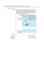
1.3.3 Internet ADSL and Home Networking via power outlet
(Bridge mode: Switch in PL/Cable side)
6
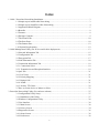
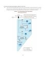
1.3.4 Internet ADSL and Home Networking via coaxial cable
(Master/Slave mode: Switch in Cable only)
In this case, the home Powerline device need to change the Private Network Name to avoid the interference from
Cable device, due to the default settings is the same. Or change the Powerline/cable 200M bridge private network
name to another name can work well too.
7
8
1.4 Benefits
‧Data transfers at up to 200 Mbps over the household power circuit or coaxial cable
‧Ranges of 200 meters
‧No need new wires for Home networking
‧Deliver the benefits of Ethernet without the wiring expense
‧Send even large files between PCs without long waits
‧High-speed Internet and DVD-quality video streaming
‧Fully compliant with IEEE 802.3, IEEE 802.3u
‧Privacy through DES encryption
1.5 Features
‧Use the home's existing Powerline or coaxial cable
‧Support coexist with Powerline 85M or 14M bridges
‧Easy to install
‧Throughout the whole house, just use your power circuit to access the Internet or PC network
‧Orthogonal Frequency Division Multiplexing for high data reliability in noisy media conditions
‧Integrated Enhanced Quality of Service(QoS) features: Eight levels of prioritized random access, contention
free access, and segment bursting
‧Up to 200Mbps data rate on Powerline or coaxial cable
‧Provide 128-bit AES Link Encryption with key management for secure Powerline communications
‧Master/Slave mode support (coaxial cable link only)
‧Up to 252 slaves with 1 master, 253 total devices for cable link
‧Up to 4 masters with up to 1008 slaves, 1012 total devices in 4 AVLNs for cable link
‧Up to 4096 addressable devices including bridged devices
1.6 Package Contents
‧Powerline/Cable 200M Ethernet Bridge unit
‧Utility & Manual CD
‧Quick Installation Guide
‧Category 5 cable
9
1.7 The Front LEDs
LED
State
ON
Powerline network activity.
OFF
Search or no Powerline network activity.
ON
Ethernet connection is OK.
LINK
ETH
Description
Flashing Data transfer.
POWER
OFF
No link to Ethernet.
ON
Power on.
OFF
Powerline off or failure.
1.8 The Rear Ports
Connector
POWER
Description
Connect to power cord.
Connect to coaxial cable. Be sure, in some countries or Europe, the coaxial connector is
Coaxial Cable
different so user need to buy extra converter to link the device to the internal TV cable not
the satellite cable.
Switch to cable only mode or Powerline/Cable mode, when switch to cable only, the
switch
Powerline function will be disable. When switch to Powerline/cable, it can enable both, so
just don’t connect to the coaxial cable, it can use as Powerline device.
LAN
Secure
Router is successfully connected to a device through the corresponding port.
If the LED is flashing, the Router is actively sending or receiving data over that port.
Button can auto secure and group the Powerline devices.
10
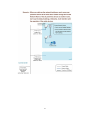
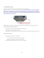
※ The Europe TV connector is different type, like the picture 1.8.1. So user need to have the converter(picture 1.8.2) to
connect the coaxial cable to the TV cable connector on the wall, don’t connect the device to the satellite connector, it
will not work.
In some countries or in Europe use
different TV connector for coaxial cable.
Picture 1.8.1
Use this converter to connect to the
coaxial cable and then connect to
the TV connector on the wall.
Picture 1.8.2
11
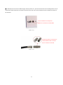
1.9 The Bottom Port
Button
Reset
Description
Push this button can reset to the factory default settings.
1.10 System Requirements
‧Ethernet device
‧AC power outlet
‧Cable link
‧Windows system for encryption setup
12
2. Cable Management Utility (For SI in coaxial cable deployment)
(For SI, as network backbone via coaxial cable and set for master/slave mode)
Note
The Device can switch to cable only, and can enable the cable link. Be sure the switch button is located at cable only
side. Basically, this utility is just for SI/ISP to setting the backbone cable network, if the user want to set at home, just
use the Powerline utility to set the device, use the hardware rear switch to change the PL/Cable or Cable only, and
set the device as bridge mode(default setting) at home.
Introduction of Configuration Utility
The Configuration Utility for Windows OS enables the user to find Powerline Ethernet devices on the Powerline
network; measures data rate performance, ensures privacy, performs diagnostics and secures Powerline networks.
Before install the utility, please check the windows edition of your computer. Now the cable management is only
support windows XP, 2000, 2003, Vista 32.
Configuration Utility Setup
Installation of the Utility
Please verify that no other Powerline Management Utilities are installed before installing this product. If other utilities
are installed, uninstall them and restart before installing this software.
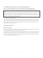
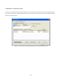
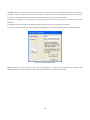
To install, insert the Windows OS Configuration Utility Setup utility CD-ROM into the computer's CD-ROM drive. The
Setup utility shall run automatically. Choose the correct one utility to install or user can manually install by double
clicking the setup.exe file when browse the folder. The CD will launch an installation utility similar to the one shown
in Figure 3.1, please click the Next button to continue.
13
Figure 2.1.
Common Features of Tabbed Windows
Status Bar
The status bar, along the bottom of each window, contains five fields that provide important network information.
• The first field contains the status of the Device Manager in respect to connection to a Powerline device.
‘Connected’ indicates a local device has been identified. ‘Not connected’ indicates no device has been found.
• The read only drop down box of the second field lists the available network adapters found on the system. Use the
drop down box to select the appropriate adapter for connection to the local Powerline device.
• The third field lists the MAC Address of the connected node.
• The fourth field lists the firmware version of the locally connected node.
• The fifth field serves as a status indicator for the various download functions of the Device Manager, displaying a
progress bar and messages pertaining to the various stages of operation.
14
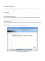
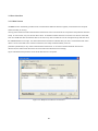
2.1 Network Information Tab
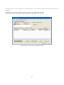
This window is an Operation Analysis window that reveals Network information in three categories: CCo Information,
Connected STA Information and Topology.
2.1.1. Topology
The ‘Topology’ group shows the TEI, MAC Address, Bridged MAC Address and the transmit (Tx) and receive (Rx)
Coded and Raw PHY rates for all nodes on the network (other than the local STA).
The ‘Coded’ rates exclude FEC bits.
The ‘Raw’ rate is the actual channel bit rate. The Raw rate is determined by carrier bit loading and the applied
HomePlug AV Tone Mask which utilizes 917 carriers out of a possible 1155.
If all carriers were to be utilized with maximum bit loading on all 1155 carriers, the Raw channel rate would be
approximately 250 Mbps.
With the HomePlug AV Tone Mask applied, the maximum Raw channel rate is approximately 200 Mbps (198 Mbps
maximum actual).
Factory Defaults: Press this button can reset the settings to the factory default.
Figure 2.2: Network Information Tab
15
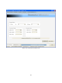
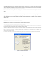
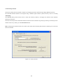
2.2 Configuration Tab
This Configuration is used to set or change the cable configuration, when the switch be selected in cable mode. It
can enable the Master/Slave function for the device. In the cable network, one cable can set as Master and link to
the other 63 salves. Set master / slave mode can easy to secure the cable network and each slave can not find the
other slaves, only link to master, very similar like central control system.
The Selection Box controls the cable enable / disable. Be sure to push the set button when you want to save the
settings. Please refer to the caution, too. Press Set button to save the settings.
Figure 2.3: Configuration Tab
16
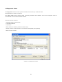
2.3 Encryption Tab
This Encryption window is used to set or change the network password on a remote device identified by its DAK
password. Clicking the ‘Set’ button sets the entered passwords. If the DAK password field is left blank, then clicking
the ‘Set’ button will set local device with the entered password. The ‘Set Encryption for Remote device’ checkbox
should be selected to set the Network Password for the remote device.
The Push Button controls box includes the ‘Action’ drop down box that provides a choice of three actions {Simple
Connect, NMK Randomize and AVLN Status} signaled to the device when the ‘Simulate Button Push’ button is
pressed. Additionally, two configuration parameters are exposed in the ‘PIB Controls’ sub-group box.
Figure 2.4: Encryption Tab
17
2.4 Link Information Tab
2.3.1. Link Characteristics Box
The context of the link is identified with the Source and Destination address boxes in the Link Characteristics group
box. The Source Address defaults to the address of the device selected in the Device Selection box on the lower left
of the tab and the Destination Address is selected from a drop down list.
2.3.2. Ethernet Controls
The Ethernet Controls are populated once the Retrieve button is pushed and indicate the PHY settings of both ends
of the link.
Figure 2.5: Link Information Tab
18
2.5 Connection Information Tab
The Connection Information window is used to acquire statistics for both transmit and receive operations in the
local or remote network.
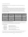
2.5.1. Connection Select
The ‘Connection Select’ group is used to identify the type of connection (TDMA or CSMA) before statistics are
acquired. The TDMA radio button is grayed out because it is not supported in this version of the Device Manager.
When CSMA is selected, the Destination Address (DA) drop-down menu may be used to select ALL devices or
specific devices in the network. In addition, Channel Access (CA) priority can be defined using the second
drop-down menu. The DM allows only certain valid combinations that can be selected by the user. The following
table describes the combinations.
Device Selection
Destination Address (DA)
Channel Access priority
Allowed
Local device
All
All
Yes
Local device
Remote device
All
Yes
Local device
Remote device
CA0 or CA1 or CA2 or CA3
Yes
Local device
Local device
Any
No
Remote device
All
All
Yes
Remote device
Local device
All
Yes
Remote device
Local device
CA0 or CA1 or CA2 or CA3
Yes
Remote device
Remote device
Any
No
2.5.2. Transmission and Reception Statistics
The ‘Transmission and Reception Statistics’ groups return operational data regarding MPDU’s and packet data unit
handling. Results shown in these fields provide valuable connection quality information.
Transmission Statistics
MPDUs Ack'd
MPDUs Collided
MPDUs Failed
MPDUs sent with SACK received
MPDUs sent with no SACK received
MPDUs sent with SACK ‘out of resources’ received
Reception Statistics
MPDUs Recvd
MPDUs received and acknowledged
MPDUs Failed
MPDUs not received due to out resources (SACK sent)
The ‘Enable Statistics’ button is used to acquire the operational data and the ‘Clear Statistics’ button is used to clear
the fields of data. The values shown by the Device manager is a cumulative total of the packet data that was
collected from the start of either the ‘Enable Statistics’ button or the ‘Clear Statistics’ button click.
19
Figure 2.6: Connection Information Tab
20
2.6 QoS Tab
QoS requirements are different for various data types such as streaming video or music, voice and raw data. To
provide higher QoS for streaming data, priority levels can be set using tags at the beginning of data frames. Virtual
Local Area Network (VLAN) 802.1p priority tags on Ethernet frames are used to specify 8 (0 – 7) levels of ‘user
priority’. HomePlug AV powerline allows for 4 levels of Channel Access Priority (CAP (0 – 3)). Therefore, the 8
levels of VLAN Ethernet tags must be mapped to the 4 levels of CAP priority, where CAP 3 is the highest priority and
CAP 0 is the lowest. CAP 3 priority might be used for voice and network management frames, CAP 2 is used for
streaming video and music while CAP 1 and CAP 0 are used for data. Mapping VLAN tags or TOS bits to CAP levels
is easily done using the VLAN Priority Mapping function on the QoS tab window.
2.6.1 List Views
The QoS tab includes two list views to provide simple channel access priority (CAP) classification for individual MAC
addresses and IP Ports. There is a collective limit of eight across both lists. No delimiters, colons, or dashes are
allowed in the MAC address format.
To write these to the PIB, and other QoS related values found on this tab, the Download PIB checkbox found on the
Configuration tab must be checked before exercising the Write button.
2.6.2 Priority Mapping
The ‘Priority Mapping’ group contains both VLAN and TOS Bit mapping capability. When selected, packets matching
the VLAN or TOS Bit priority will be assigned the Powerline contention priority (Channel Access Priority, CAP) as set
in the corresponding dropdown box. If a packet has both VLAN and TOS in it, VLAN will override TOS.
2.6.3 Default CAP
The ‘Default CAP’ group allows for default priority mapping of packets that do not have a VLAN or TOS bit (or if
these are disabled). Settings are available for Unicast (directed to a host).
ٛ
IGMP - (default CAP 3) - sets the channel access priority for IGMP frames - these are the group management
frames, not the stream data
ٛ
Unicast - (default CAP 1) - sets the default channel access priority for unicast frames not matching any other
classification or mapping.
ٛ
IGMP managed Multicast Stream (Fixed to CAP 2) - sets the default channel access priority for stream data
belonging to a snooped IGMP multicast group.
ٛ
Multicast/Broadcast - sets the default CAP for multicast frames not in a snooped group and for broadcast
frames.
After making CAP settings, clicking the Write button will commit these, along with the values from the Configuration
tab, to NVRAM on the connected device.
2.6.4. IGMP
21
The ‘IGMP’ group includes controls to disable the query timeouts. Checking the ‘Override Defaults’ box will
enable the other boxes as choices.
2.6.5. Priority TTL Value
The ‘Priority TTL Value’ determines the life span (Time to live) of each packet in the buffer of the AV device that
will be sent over the powerline subsequently. This value can be varied from 10 msec to 65000 msec which can
be mapped to different levels of Channel access priority traffic. The default values used are stored in the PIB file
as shown below:
CA0 traffic: 2000 msec (used for TCP data traffic)
CA1 traffic: 2000 msec (used for TCP data traffic)
CA2 traffic: 300 msec (used for UDP video/music traffic)
CA3 traffic: 300 msec (used for VoIP traffic)
Highly recommends that the 300 msec and 2000 msec default settings not be changed because they are optimized
for the above stated traffic.
Figure 2.7: QoS Tab
22
2.7 How to set the device to Master or Slave
PL/Cable Mode: Bridge Mode is usable for Home. Signal is transmitted with AC Power on the outlet.
Step.1
Please set the switch behind the device in PL / Cable.
Step.2
Open the Device Manager Utility and connect the device to computer , and check the utility that is connected to the
device.
23
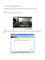
Step.3
Select the Configuration tab and disable the Master or Slave Configuration.
(Default is disable.)
Step.4
Click the “ Write ” button , the setup will write to the device , and the device will reset.
24
Cable Only Mode Cable Only Mode is usable for ISP. Signal is transmitted with coaxial cable.
Step.1
Please set the switch behind the device in Cable Only.
Step.2
Open the Device Manager Utility and connect the device to computer , and check the utility that is connected to the
device.
25
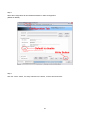
Step.3
Enable the Cable Mode and select Master or Slave you want to set.
Step.4
Click the “ Write ” button , the setup will write to the device , and the device will reset.
26
3. Powerline Networking Utility (For end user at home)
Note. The Powerline Device can auto detect the other powerline bridges which plug in the same power circuit, you
don’t need to use this powerline utility except you want to encryption all the powerline devices as the same group or
you can not access the other computers. Basically, use the hardware rear switch to change the PL/Cable or Cable
only to decide the link way via Powerline or Coaxial cable, and set the device as bridge mode(default setting) at
home.
Introduction of Configuration Utility
The Configuration Utility for Windows OS enables the user to find Powerline Ethernet devices on the Powerline
network; measures data rate performance, ensures privacy, performs diagnostics and secures Powerline networks.
Before install the utility, please check the windows edition of your computer. For vista 64, it need to install the vista
64 utility, you can easy to see it in the CD auto run screen. Please use the correct utility to install; otherwise it can
not work properly.
3.1 Configuration Utility Setup
3.1.1 Installation of the Utility
Please verify that no other Powerline Management Utilities are installed before installing this product. If other utilities
are installed, uninstall them and restart before installing this software.
To install, insert the Windows OS Configuration Utility Setup utility CD-ROM into the computer's CD-ROM drive. The
Setup utility shall run automatically. Choose the correct one utility to install or user can manually install by double
clicking the setup.exe file when browse the folder. The CD will launch an installation utility similar to the one shown
in Figure 1.
This Utility is designed for Powerline 85M/200M Ethernet bridges. Click the Next button to continue.
27
Figure 3.1: Install Shield Screen
28
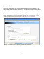
3.2 Windows Configuration Utility
In order to run the utility, double-click the utility icon. Figure 2 shows the main screen of the configuration utility.
This screen shot shows a Powerline Ethernet device connected as a local device and other Powerline Ethernet
devices as remote devices.
Figure 3.2: Main Screen with High-Speed Powerline Ethernet device Local
29
3.3 User Interface
3.3.1 Main Screen
The Main screen essentially provides a list of all Powerline Ethernet devices logically connected to the computer
where the utility is running.
The top panel shows all local Powerline Ethernet devices found connected to the computer's NIC (Network Interface
Card). In most cases, only one device will be seen. In situations where there are more than one device connected,
such as a USB and also an Ethernet device, the user may click to select the one to manage through and then click
the Connect button to its right. The status area above the button indicates that your PC is connected to that same
device. Once connected to the chosen local device, the utility will automatically scan the
powerline periodically for any other Powerline Ethernet devices. If no local Powerline Ethernet devices are
discovered, the status area above the connect button will indicate that accordingly.
Figure 3 illustrates the presence of two local devices in the computer.
Figure 3.3: Multiple Local Device Connection
30
The lower panel displays all the Powerline Ethernet devices, discovered on the current logical network (remote
devices). Displayed immediately above this panel is the number of remote devices found, the type of logical network
(Public or Private), and a message area that reports connectivity
and scan status. The following information is displayed for each of the devices discovered that appear in the lower
panel:
Device Name column shows the default device name, which may be user re-defined. A user may change the name
by clicking on the name and editing in-place, or by using the rename button. An icon is optionally shown with the
name. A distinction in icons is made between low-speed and high-speed devices . By default, the icon is displayed
with the name.
MAC Address column shows the device's MAC address.
Password column shows the user-supplied device password (initially left blank).
A user may enter the password by using the Enter Password button.
To set the Password of the device (required when creating a private network), first select the device by clicking on
its name in the lower panel and then click on the Enter Password button.
A dialog box will appear as shown in Figure 4 to type the password. The selected device name is shown above the
field for entering the password. Hit OK after entering the new password. A confirmation box will appear if the
password was entered correctly.
If a device is not found, the user will be notified and suggestions to resolve common problems will be presented.
Figure 3.4: Set Device Password
31
The Add button is used to add a remote device to your network that is not on the displayed list in the lower panel, for
example, a device currently on another logical network. Users are advised to locate the passwords for all devices
they wish to manage and add them to the local logical network by clicking on the Add button.
A dialog box will appear as seen below. The dialog box allows the user to enter both a device name and the
password.
A confirmation box will appear if the password was entered correctly and if the device was found.
If a device is not found, the user will be notified and suggestions to resolve common problems will be presented.
Figure 3.5: Add Remote Device
Note: The device must be present on the power line (plugged in) in order for the password to be confirmed and
added to the network. If the device could not be located, a warning message will be shown.
32
The Scan button is used to perform an immediate search of the Powerline Ethernet devices connected to the
computer.
By default the utility automatically scans every few seconds and updates the display.
A typical screen after naming and supplying passwords might appear as in Figure 6.
Figure 3.6: Main Screen of the Configuration Utility
33
3.3.2 Privacy Screen
The Privacy dialog screen provides a means for managing the local network and providing additional security.
All Powerline Ethernet devices are shipped using a default logical network (network name), which is normally
“HomePlug”.
The Privacy dialog screen allows user to make the network private by changing the network name (network
password) of devices.
The user can always reset a Powerline Ethernet network to the universal one (public) by entering “HomePlug” as the
network name or by clicking on the Use Default button.
Note: Changing the network name to any other name other than HomePlug will show the network type on the main
screen as Private.
Figure 3.7: Privacy Screen
34
The Set Local Device Only button is used to change the network name (network password) for the local device
only.
After doing this, all the devices seen on the Main panel prior to this will no longer be able to communicate or respond
to the computer, as they will be on a different logical network. Devices previously set up with the same logical
network (same network name) will appear in the device list afterward selecting this option.
The Set All Devices button is used to change the logical network of all devices that appear on the Main panel.
The user must have entered the device's Password in order to set it to the new logical network. A notification
message will appear to report the success of this operation.
35
3.4 Diagnostics Screen
The Diagnostics screen shows system information and a history of all devices seen.
The appearance is shown in Figure 8.
The upper panel shows technical data concerning software and hardware on the host computer used to
communicate over Powerline Ethernet Network.
It shall include the following:
‧Operating System Type/Version
‧Host Network Name
‧User Name
‧MAC Address of all NICs (network interface card)
‧Identify versions of all Driver DLLs and Libraries used (NDIS) and optionally
‧MAC Firmware Version
Figure 3.8: Diagnostics Screen
36
The lower panel contains a history of all remote devices seen on the computer, over time. Devices are shown here
regardless of whether or not they are on the same logical network. Devices that are active on the current logical
network will show a transfer rate in the Rate column; devices on other networks, or devices that may no longer exist
are shown with an “?” in the Rate column.
The following remote device information is available from the diagnostics screen:
‧Adapter Alias Name
‧Adapter MAC Address
‧Adapter Password
‧Adapter Last known rate
‧Adapter Last Known Network
‧Date device last scanned
‧MAC Firmware Version
The diagnostics information displayed may be saved to a text file for later emailing to technical support of a
manufacturer or printed for reference during a technical support call. Devices no longer part of the network can be
deleted using the delete button.
37
3.4.1 About Screen
The screen shows the software release date.
Figure 3.9: About dialog screen
3.4.2 Preferences
The lower part of the panel may display options for user preferences (such as turning the auto-scan feature
on or off) as shown Figure 9 above.
38
4. Push Button Setting
There are 2 buttons in this device, one is Reset button the other is Secure button.
Reset: Push this button can reset to the factory default settings. Be careful, when you press the reset button,
please make sure unplug (remove) the Ethernet cable (RJ-45cable) first, and then press the reset button.
After press the reset button (the time need < 3 sec) and then wait the PWR LED light again. Don’t power off
when the device is in reset process.
Secure button can auto secure and group the Powerline devices, the follow is the scenario for secure button.
Two Push Button trigger state conditions
“Adder state” for a device providing the NMK for an existing AVLN
“Joiner state” for a device that will join an AVLN
Pushing buttons on any two devices results in one of them becoming an “adder” and the other one a “joiner”
Three possible scenarios
Unassociated device joining an existing AVLN
–
Two Unassociated devices joining to form a new AVLN
–
Special case: one device is a CCo, the other is a STA
Two Associated devices joining to form an AVLN with a new NMK
39
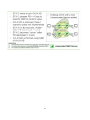
Possible Use Case Scenario 1: Unassociated device joining existing AVLN
Possible Use Case Scenario 2: Two devices joining to form new AVLN
Before this scenario begin, please make sure to press each device secure button > 10 sec till all LEDs
re-flash to generate the random network password key first.
Possible Use Case Scenario 3: Reset
40
41
5. Trouble Shooting
1. Why my utility can not work properly after finish install steps?
Ans:
Please follow the steps to check the problem.
1.
Check the Windows version, the utility only can support windows 2000, XP, 2003, vista 32, Vista 64.
2.
Reinstall the utility again, you can remove it and reinstall the utility again.
3.
If the OS is vista 64, make sure you install the correct utility for vista 64. You can see it in CD auto run
utility page.
2. What kind of windows OS can install the Powerline utility?
Ans:
Now the Powerline utility only supports Windows 2000, XP, 2003 and Vista 32/64.
3. Why the throughput of Powerline 200M bridge is bad?
Ans:
Please follow the steps to check the problem.
1.
Due to the master/slave structure, you need to avoid plugging two Powerline bridge in the same time,
so you had better plug the Powerline to the power outlet sequence.
2.
Please unplug the Powerline bridge and plug again, please remember plug them in sequence.
Check the Powerline utility and check the throughput again.
4. Why the Powerine 200M device can not work stable?
Ans:
In some respects, User had better to adjust the NB/PC NIC's connection type setting to 100MBaseTx half
duplex while connect to powerline 200M device. It will keep the performance to the best status and stable.
When user found the link is unstable or not good, please change the NIC's connection type setting to half
duplex.
42
5. Why the Cable master unstable when set as master/slave in cable mode?
Ans:
If the slave sides use the Powerline device too, please change the default private network name to others.
The application as follows.
43
6. If need to use the Powerline/Cable in home, how can I do?
Ans:
If the Powerline/Cable 200M Bridge need use with Powerline Bridge, the switch need switch to PL/Cable
mode and set the Powerline/Cable 200M Bridge to Bridge mode, due to keep the high performance, use
the high-pass filter to filter the signal interference from cable modem, the application as follows.
44