1
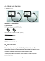
2.4GHz Digital Wireless System CAUTION! RISK OF ELECTRIC SHOCK. PLEASE DO NOT REMOVE COVER WHEN POWER CONNECTED. NO USER SERVICEABLE PARTS INSIDE. REFER SERVICING TO QUALIFIED SERVICE PERSONNEL. NOTE: this equipment has been tested and found to comply with the limits for a Class “A” digital device, pursuant to Part 15 of the FCC Rules. These limits are designed to provide reasonable protection against harmful interference when the equipment is operated in a commercial environment. This equipment generates, uses, and can radiate radio frequency energy and, if not installed and used in accordance with the instruction manual, may cause harmful interference to radio communications. FCC Caution: to assure continued compliance, use only shielded interface cables when connecting to computer or peripheral devices. Any changes or modifications not expressly approved by the party responsible for compliance could void the user’s authority to operate this equipment. This Class A digital apparatus meets all the requirements of the FCC Regulations. 1 A、What is in the Box 1. TX/RX Module Receiver x 1 Transmitter x 1 2. Accessories 2.1 Power Adaptor x 2 (DC12V/1A) 2.2 Antennas x 2 (9dBi or 3dBi, option) 2.3 This user manual x 1 B、Introduction Thank you for purchasing this 2.4GHz Digital Video Sender. This transmission system is a digital wireless video sender that uses 2.4GHz Frequency Hopping technology(not fixed frequency) and 16QAM/QPSK/BPSK modulation, and random ID codes to protect personal privacy. 2 There are over billion hopping sequences to minimize interference and deliver consistently an excellent video quality up to 250M meters away by 100mW transmission power and high gain antenna, you may use higher gain antenna to increase the distance. Using this 2.4GHz Digital Wireless Video Sender, you can enjoy greater convenience and security in many ways. Safety & Security Application: Connect a PTZ camera as a wireless security system, control its Pan/Tilt/Zoom actions via RS485 port from the receiver(RX), through PTZ keyboard or DVR with PTZ function C、 Product Layout and wire connection TX/RX Outlook Antenna Connector RS485 port(+ -) to (SMA Jack) connect PTZ + - Video Jack for PTZ camera input(TX) or output(RX) DC jack for power adaptor 3 RS485 control wirelessly Connect RS485 leads of TX module to PTZ Camera RS485 port, and connect RS485 leads of RX module to RS485 port of PTZ keyboard or DVR, so that PTZ Camera can be wireless controlledfor long distance. Step 1. Installation – TX module The TX module includes one of BNC video drop cable to connect our video source equipment (camera), one pair of RS485 leads, and one power drop cable. 1. Screw an antenna onto the SMA connector on the back of the TX module. 2. Locate the TX module close enough to your video source to connect to them. Use appropriate fasteners to anchor the TX module to the mounting surface. 3. Connect a BNC video/power extension cable (not provided) to Video In and Power drop cables of the TX module, then to your video source (camera) and 12 VDC power adapter (provided). 4. Connect the RS485 leads of the TX module to the local RS485 PTZ equipment you want to control, if needed. Step 2. Installation – RX module The RX module includes one of BNC video drop cable to connect our video monitor/recording equipment (TV/DVR), one pair of RS485 leads, and one power drop cable. 4 1. Screw an antenna onto the SMA connector on the back of the RX module. 2. Locate the RX module close enough to your video recorder and RS485 controller to connect to them. Use appropriate fasteners to anchor the TX module to the mounting surface. 3. Connect a BNC video/power extension cable (not provided) to Video Out and Power drop cables of the RX module, then to your monitor/recording equipment (TV/DVR) and 12 VDC power adapter (provided). 4. Connect the RS485 leads of the RX module to the local RS485 PTZ controller, if needed. Step 3. Pairing the TX and RX modules The TX and RX modules of each product are factory configured to synchronize only with each other. Effective synchronization is achieved when the video carried through the system can be seen at the video recording or monitoring equipment connected to the RX module, and an RS485 controller at the RX module can control a PTZ device connected to the TX module. Synchronization of a single TX/RX module pair occurs automatically after the TX and RX modules are powered on. If synchronization is lost, it can be re-established by powering off, then powering on one of both of the modules. After powering off either module, wait 10 seconds before powering it on again. To automatically synchronize a TX and RX module pair: 1. Plug the 12VDC power adapter for the TX module into a wall outlet. 2. Plug the 12VDC power adapter for the RX module into a wall outlet. 3. Verify that you can see video from your video source equipment at your video recorder. 4. Verify that you can control the remote RS485 (PTZ) device using your RS485 controller. 5 Note: 1. PTZ protocol of this system is Pelco P orPelco D only. It can be auto detected, and itmust be the same between PTZ camera and PTZ keyboard or DVR. 2. The default baud rate of TX and RX module is 2400bps.The PTZ camera, PTZ keyboard or DVR must be setup with same baud rate. 3. RS485 leads must be connected correctly. The yellow wire is positive (+ or A) and the white wire is negative (- or B). Multiple TX/RX systems When setting up multiple systems in the same vicinity, observe the following guidelines: Place RX modules at least 1 ft apart. Power on each TX and RX module pair one at a time and allow the pair to synchronize as described above before powering on another module pair. Note If multiple systems are setup in the same vicinity and pairing is lost between one or more TX/RX module pairs, power off the modules of the pairs that failed, then power on each pair one at a time and allow it to synchronize before powering on another pair. D、 Usage Notices 1. Be sure the transmitter and the receiver were connected to the equipment correctly (e.g. Connect the transmitter to the camera, and the receiver to the TV or DVR). 2. When DC plug is pulled out from transmitter or receiver, it needs to wait for a few seconds to insert it again. 3. Adjust antenna to decrease interference. (vertical or horizontal) 4. In most situations, one pair has a better distance up to 250M (line of sight and open sight). When two pairs or more are used at the same time, It can automatically jump to different channels. But the distance 6 between transmitter and transmitter (receiver and receiver), preferably greater than 2 meter far. E、 Troubleshooting Problems Possible Solution 1. Monitor(RX) shows Please check ifcamera power off or broken, “No Video Signal” camera cable disconnected or damaged. 2. Monitor(RX) shows Please check if TX power off, TX/RX distance is “No Signal” too longso that transmission signal is weak. Check all cable connections Make sure power plugs are pushed well. Check power switches on the remote TV or DVR 3. No picture and Video source (Camera, Camcorder, etc.) Adjust receiver and transmitter antenna orientation Try to place transmitter and receiver a little more close The transmission path between the pair may be overlapped to the other pair, must install higher 4. Interference: picture position or separate these two pairs There would be a high power pair unit near by TX or RX, please find it and move Make sure video signal transmission is OK. Otherwise, refer 1 or 2. Then, check the 5. PTZ can not be interconnection is OK. Especially the RS485 controlled. lead polarity is right. After then, check if the Baud Rate of all the devices in the system is set to 2400bps, such as PTZ camera, DVR. 7 F. Specifications TX/RX: TX (Transmitter) RX (Receiver) Frequency Band 2.400GHz~2.4835GHz Modulation 16QAM/QPSK/BPSK Video Input Level 1V p-p @75 ohm RS485 Port control PTZ camera Baud Rate 2400 bps (Default Value) Antenna omni antenna 9dBi or 3dBi (option) PA Output Power 100mW —— Receiver Sensitivity —— -85dBm min. Power Consumption 1.9W Waterproof grade IP66 Power Supply 12V/1A Dimensions 160mm x 123mm x 37mm Weight 435g System: Transmission Channels 80 channels, auto selection Video Bit Rate up to 12 Mbps Random ID Code up to 4 million sets Video Resolution 720 x 480 @ 30 fps (NTSC) or 768 x 576 @25 fps (PAL) PTZ Control Protocol Pelco D or Pelco P, auto detect Baud Rate 2400 bps Operational Range up to 250M~350M depends on the antennas (line of sight and open sight) ●All specification subject to change without notice 8