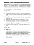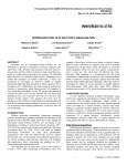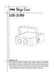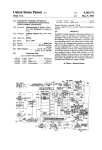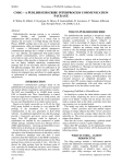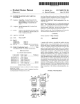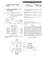
1
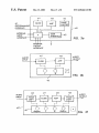
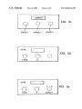
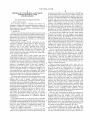
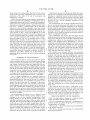
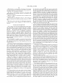
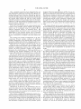
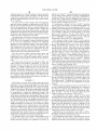
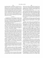
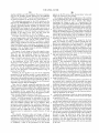
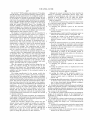
US006564112B1
(12) United States Patent
(10) Patent N0.:
(45) Date of Patent:
Factor
(54) METHOD OF CUSTOMIZING ELECTRONIC
SYSTEMS BASED ON USER
SPECIFICATIONS
US 6,564,112 B1
May 13, 2003
“Orville Presets V2.600” dated Aug. 18, 1999 (pp. 1—8) and
tWo—page document entitled “Read Me First!”, dated Aug.
18, 1999, Eventide, Inc.
(75) Inventor: Richard Factor, Kinnelon, NJ (US)
OrvilleTM Programming Manual (Eventide, Inc., part No.
141035, Manual Release 1.1, Jul. 28, 1999, pp. 1—97 (entire
(73) Assignee: Eventide Inc., Little Ferry, NJ (US)
document).
(*)
OrvilleTM Modules Manual (Eventide, Inc., part No.
141035a, Manual Release 1.1, Jul. 29, 1999, pp. 1—98 (entire
Notice:
Subject to any disclaimer, the term of this
patent is extended or adjusted under 35
U.S.C. 154(b) by 0 days.
document)).
VSIGFILE User Manual V1.0 (Eventide, Inc., Jan. 13, 1997,
(21) Appl. No.: 09/437,771
(22) Filed:
pp. 1—22 (entire document)).
NOV. 8, 1999
* cited by examiner
(51)
Int. Cl.7 .............................................. .. G06F 19/00
(52)
US. Cl. .... ..
(58)
Field of Search ............................ .. 700/94, 95, 97,
.. 700/97; 700/95; 703/13;
716/1
700/103, 104, 105; 703/1, 13; 705/26; 716/1,
5, 16
(56)
Primary Examiner—Leo Picard
Assistant Examiner—Paul Rodriguez
(74) Attorney, Agent, or Firm—Ostrolenk, Faber, Gerb &
Soffen, LLP
(57)
References Cited
ABSTRACT
A method and system for manufacturing a particular system
U.S. PATENT DOCUMENTS
based on a universal system. The method includes designing
5,068,823 A
* 11/1991
Robinson ................... .. 716/16
the particular system on the universal system. The particular
5,812,414
*
Butts et a1.
system as implemented on the universal system is then
A
9/1998
.......
5,966,310 A
* 10/1999
Maeda et a1. ...... ..
6,006,195
*
Marchak et a1.
A
6,167,383 A
12/1999
* 12/2000
. . . ..
703/13
345/866
.....
. . . .. 700/95
Henson .................. .. 703/13
6,202,197 B1 *
3/2001 Robinson et a1. .
6,236,901 B1 *
5/2001
703/14
Goss ................. ..
361/692
6,249,714 B1 *
6/2001 Hocaoglu et a1.
6,393,591 B1 *
6,438,435 B1 *
5/2002 Jenkins et a1. ..... ..
714/725
8/2002 Wada et a1. ................ .. 700/97
700/28
OTHER PUBLICATIONS
tested. The system is re-designed and re-tested until the
particular system as tested on the universal system is accept
able. The ?nal design of the particular system is sent to a
manufacturer to be built using the elements of the universal
system used to implement the particular system. After the
manufacturer receives the design of the particular system as
implemented on the universal system, it identi?es the ele
ments of the universal system used to implement the par
ticular system. The particular system is constructed using
OrvilleTM Operating Manual (Eventide, Inc., part No.
141032, Manual Release 1.1, Jul. 28, 1999, pp. 1—111 (entire
those elements of the universal system.
9 Claims, 8 Drawing Sheets
document).
EXTERNAL
INPUTS
70
r
\
l
E
l l 1'1 t‘776
M1
M2
‘M3
0 o 0
MN
P
003519114]?
./ 11m
EXTERNAL
OUTPUTS
14
21
U.S. Patent
May 13, 2003
Sheet 1 of 8
US 6,564,112 B1
EXTERNAL
10
‘ INEUTES g
'
\
,H/ 76
J! i J}- J
M1
M2
1M3
0 a a
MN
P
z
4/
"
r;i
/
n u
21
O 0 I] U
/
20
/
E
mi
lg [F
0
_
a
,2/ l l l 1W8
EXTERNAL
FIG. 1
ourpurs
CUSTOMER
MANUFACTURER
XYZ CO.
[1D
0
% COM "
[1E]
22
—
POWER
PENSATION ‘CHANNEL
FIG. 2
U.S. Patent
May 13, 2003
Sheet 2 of 8
US 6,564,112 B1
CUSTOMER DESIGNS A
PARTICULAR SYSTEM
ON A UNIVERSAL SYSTEM
CUSTOMER TEsTs THE
PARTICULAR SYSTEM AS
IMPLEMENTED ON THE
UNIVERSAL SYSTEM
L-—
CUSTOMER
SATISFIED WITH
THE TEST REsULTs
NO
?_
CUSTOMER
RE-DESIGNS THE
PARTICULAR SYSTEM
0N THE UNIVERSAL
SYSTEM
YES
CUSTOMER SELECTS ONE OF A NUMBER
OF FRONT PANELS OFFERED BY A
MANUFACTURER HAVING A CONFIGURATION
OF CONTROL INTERFACES(KNOBS,BUTTONS, ETC.)
AND ADAPTS THE DESIGN 'OF THE PARTICULAR
SYSTEM SO THAT ITS ADJUSTABLE VARIABLES
INTERFACE WITH THE CONTROL INTERFACES,
AND DESIGNS LABELS AND ART WORK FOR THE
PANEL SELECTED.
CUSTOMER SEND'S THE DESIGN OR SELECTION
' THE PARTICULAR SYSTEM AND
THE DESIGN OF THE FRONT PANEL
TO A MANUFACTURER
FIG. 2a
U.S. Patent
May 13, 2003
Sheet 3 of 8
US 6,564,112 B1
MANUFACTURER RECEIVES DESIGN
OF THE PARTICULAR SYSTEM
AND THE FRONT PANEL
MANUFACTURER IDENTIFIES THE
ELEMENTS OF THE UNIVERSAL
SYSTEM NEEDED TO IMPLEMENT
THE PARTICULAR SYSTEM
MANUFACTURER CONSTRUCTS THE
MANUFACTURER
PARTICULAR SYSTEM USING THosE
ELEMENTS OF THE PARTICULAR
SYSTEM AS IMPLEMENTED IN THE
UNIvERsAL SYSTEM
TESTS THE PARTICULAR
SYSTEM AND TROUBLE
SHOOTS SYSTEM, IF
NECESSARY
MANUFACTURER CREATES LABELS AND
OTHER ARTWORK FOR THE FRONT PANEL
SELECTED BY THE CUSTOMER
MANUFACTURER INTERFACES THE ADJUSTABLE
VARIABLES OF THE DESIGNED SYSTEM WITH
THE CONTROL INTERFACES OF THE PANEL
SELECTED BY THE CUSTOMER
FIG. 2b
U.S. Patent
May 13, 2003
Sheet 4 of 8
US 6,564,112 B1
MANUFACTURER TESTS THE COMPLETED
SYSTEM
MANUFACTURE TROUBLESHOOTS AND
CORRECTS PROBLEMS IN THE
COMPLETED SYSTEM, IF ‘NECESSARY
i
MANUFACTURER DELIVERS THE
COMPLETED SYSTEM TO THE
CUSTOMER
FIG.- 2c
U.S. Patent
May 13, 2003
FILTER
PC
PROGRAMMING
INTERFACE
US 6,564,112 B1
Sheet 5 0f 8
PHASE
SHIFTER
AMP
/40
EXTERNAL
USER
INTERFACE
INPUT
INTERFACE
P42
FIG. 3a
EXTERNAL
OUTPUT
INTERFACE
AUDIO
OUTPUT
AUDIO
INPUT
— -- n
AMP
FILTER
in
FIG. 3 b
42
AUDIO
INPUT
40’f
PHASE
SHIFT
_--~
FILTER
---
AMP
PHASE]
SHIFT
v
AUDIO
OUTPUT
U.S. Patent
May 13, 2003
Sheet 6 6f 8
US 6,564,112 B1
DISPLAY
9 9 9
/
I
I
KNOB 1
KNOB 2
KNOB 3
\\'% I’
O
3C
ACME
\UOII
1‘ (Hz)
ACME
Q‘ 1,
\C‘j,
f(Hz)
%
FIG. 3e
DISPLAY
U.S. Patent
May 13, 2003
Sheet 7 of 8
US 6,564,112 B1
“Ll 15M]
FINZ >J [> ourzl
FIG. 4
v18
O
MODFILTER
O
.
Fl
50
FIG. 5d
U.S. Patent
May 13, 2003
Sheet 8 0f 8
@
[1N1 >]_\‘\ 50
US 6,564,112 B1
> 0M2)
58
/
[DA
/
4
8
MODFILTER
\
LFO
FIG. 5b
~48
“480
FIG. 5c
MODFILTER PARMS
A: EMPTY
FREQ:0.0 Hz
FREQ‘ MOD:0.0 Hz
q: 1.0
q, M'OD:0.0
MODFILTER
LFO
FIG. 5e
US 6,564,112 B1
1
2
METHOD OF CUSTOMIZING ELECTRONIC
SYSTEMS BASED ON USER
SPECIFICATIONS
outputs from the chips. At a fundamental level, the DSP may
be programmed With a large set of modules, Which each
contain a digital processing capability, general control func
tion and/or a mathematical function. In addition, DSP manu
facturers may create and store a set of DSP processing
BACKGROUND OF THE INVENTION
program segments, each of Which provides a certain sound,
effect, or other function for the user. These segments, or
1. Field of the Invention
The invention relates to methods and systems for
“presets”, are generally comprised of one or several mod
ules. The user typically has the ability to alter the parameters
designing, ordering and customizing electronic systems. In
particular, it relates to creating a customiZed electronic
10
sally con?gurable system.
2. Related Art
Creation of customiZed electronic systems is common and
Wide-ranging. In one Well-knoWn example, military contrac
tors are provided With detailed speci?cations by the Defense
Department; the systems are subsequently designed, con
structed and delivered to the customer (i.e., the Defense
An example of such a DSP is the OrvilleTM Audio Effects
15
viding digital signal processing capabilities, general control
and/or mathematical functions. The OrvilleTM includes hun
dreds of presets (alternatively referred to as “programs”)
con?gured in various Ways to provide a menued array of
Other familiar examples include construction of semi
customiZed computer systems such as those offered by
the particular computer and ships it to the customer. The
reverbs, pitch shifters, distortion, dynamics, equaliZation,
phasing, ?anging and other music and production effects.
25
customer, hoWever, has a limited number of stock compo
nents to choose from and cannot test the ?nal system prior
to its construction and delivery.
Electronic systems, such as audio systems, also have
longstanding practices of customiZation based on the user’s
has a number of input interfaces. Using a menu on the face
of the OrvilleTM, the user can adjust the parameters (or
variables) of the preset. For example, if the preset is a loW
pass ?lter, the user can adjust the frequency cutoff. The user
can also store the preset With the adjusted parameters as a
35
separate customiZed program.
Digital signal processing units may also be
programmable, thus alloWing the user to create his or her
oWn effects, instead of being limited to the presets or
lishments have also provided construction of complete sys
programs chosen by the manufacturer. For example, the
OrvilleTM is also programmable by the user. By using
programming accessed via the front panel of the OrvilleTM,
or by using softWare supplied by the manufacturer that is
tems or components based on a customer’s design, or its
oWn design based on a customer’s description. All of these
various schemes also suffer from the draWback that the ?rst
time the customer hears or otherWise evaluates the system or
component is after it is constructed and delivered.
Electronic systems currently exist that incorporate a Wide
range of features, functions and capabilities. Some such
systems alloW a user to design a particular system by
The user can thus invoke the presets of the OrvilleTM via
a menu to exploit their intended effect. For effects that
operate on external inputs (as opposed to, for example,
effects that are entirely generated internally), the OrvilleTM
needs. Often an audiophile or a musician becomes familiar
enough With a system or component to make the change him
or herself, often by trial and error. Commercial establish
ments have also offered customiZation services of existing
systems or components, based on the user’s design or
description of the end sound or result. Commercial estab
Processor by Eventide, Inc., the assignee of the present
invention. The OrvilleTM is a programmable, multi-channel,
digital signal processor. The OrvilleTM has tWo processors
and also includes numerous electronic modules, each pro
Department in this example).
GateWay Computers. The customer can order a computer
tailored to his or her needs, selecting items such as
processors, drives and modems. The company then builds
or variables that are used in the presets. For example, for a
?lter preset, the DSP alloWs the user to change the frequency
parameters of the ?lter. Depending on the particular DSP
function invoked, external inputs may or may not be needed.
system based on a user speci?cation created using a univer
loaded onto a PC, the user may construct a desired con?gu
ration of the modules of the OrvilleTM by selecting the
45
modules used, creating the inputs and outputs betWeen
modules and adjusting the parameters of the modules. The
con?guring and customiZing programmed features Within
the system, and then testing the con?guration. In addition,
softWare also alloWs the user to assign parameters to the
knobs and other manual controls on the front panel of the
some systems permit the user to program a particular’system
OrvilleTM, thus giving the user the ability to manually adjust
these selected (adjustable) parameters (such as gain, output
channel, etc.) for the designed effect. Meters (such as
simulated meters, including LCDs) displaying certain
parameters (such as amplitude) may also be programmed for
using more elemental features supported by the system, and
the programmed con?guration may also be tested. If the
con?guration is acceptable, the system so con?gured may be
implemented for its desired purpose. If not, it can be
recon?gured by re-programming the system until accept
able. If the speci?cations change over time, or become
unnecessary, the system may be recon?gured to the neW
speci?cations or reimplemented in a completely different
55
designed effect from the modules. The execution (or
“build”) of each such effect is done by creating program
con?guration.
ming that links the various modules together in the manner
designed by the user. The build takes only a feW seconds,
A prominent example of an electronic system described
immediately above are programmable digital signal proces
sors (DSP), including digital effects processors. Early effects
processors used analog circuitry and devices, along With
knobs and other sWitches for adjusting parameters. For
example, shift registers Were used for delay and circuitry
Was used for frequency adjustment.
With today’s DSPs, a microprocessor interfaces With DSP
chips and are programmed to create the desired effects and
display on the front panel of the OrvilleTM.
Once the effect is designed, the design is doWnloaded to
the microprocessor of the OrvilleTM, Which “builds” the
thus giving the user a near simultaneous experience of the
effect. The user can experiment by making quick changes to
the design and immediately experience the effect.
65
The programmability of the OrvilleTM and like DSPs
alloWs the user to experiment by implementing effects that
may be more complex than the presets. For example, the
user may combine modules to have a ?lter folloWed by a
US 6,564,112 B1
3
4
delay followed by a phase shift. The effect may be imme
diately built and tested. Adjustments may be made to the
parameters of the effect, or it can be re-designed and
Alternatively, the user may design and supply the manu
facturer With a completely custom design of the front panel,
including a completely custom layout of knobs, buttons,
immediately re-tested.
displays, etc. selected by the user for the front panel. These
knobs, buttons, etc. likeWise provide the control interface
While electronic systems that incorporate a Wide range of
betWeen the user and the adjustable parameters of the
features, functions and capabilities, including those that are
con?gurable, such as the Orville TM, provide the advantage of
alloWing the user to design and/or test particular functions,
particular system.
and then to recon?gure the system as desired at a later time,
the user to implement the particular system in a stand-alone
they have a number of disadvantages. Such “universal”
device. Only those constituent capabilities of the universal
system needed to support the particular system are included
in the implementation, con?gured as speci?ed by the user. In
particular, hardWare and/or softWare from the universal
system that is not needed to support the particular system is
largely or completely excluded.
The manufacturer also creates the front panel for the
particular system based upon the design sent by the user. As
noted above, this may be one of a number of particular panel
con?gurations offered by the manufacturer that the user
adapts to the designed system. Alternatively, it can be a
The manufacturer uses the design speci?cations sent by
systems are often relatively expensive, since they include
softWare and/or hardWare that provide the user With so many
options. Implementation of particular effects using the uni
versal system is thus a costly and inef?cient use of the
device, because the true poWer of the universal system is its
15
capacity to develop effects. For example, a small studio may
have a number of particular effects that it Wants to imple
ment and regularly use over an extended period of time.
Implementing a number of effects using one or a feW
OrvillesTM requires (at least) re-programming the OrvilleTM
and integrating it in the particular setting for the desired
effect. This is (at best) time consuming and tedious. It can
completely customiZed panel designed by the user for the
system. The unit created by the manufacturer also has input
and output connections that interface With the designed
delay production, or, When more simultaneous effects are
needed than available OrvillesTM, limit the desired produc
tion. Generally, a small studio Will not have (or be Willing to
system, as Well as the labels, calibrations and other artWork
25
supplied by the user. When complete, the stand-alone unit is
expend) the resources to purchase a separate OrvilleTM to
implement each effect. Finally, use of the OrvilleTM to
implement effects can hinder the Work of those developing
tested and then delivered to the user.
neW effects.
products. The customer uses the comprehensive universal
system as a design and testing tool, but does not use it to
The method is an extremely ef?cient and economical
method and system for constructing highly customiZed end
SUMMARY OF THE INVENTION
actually implement particular systems. The customer may
use only a small fraction of the capabilities of the universal
The invention includes a commercial method of custom
iZing a particular system from a universal system having
numerous constituent capabilities that, are con?gurable. The
user designs a particular system and implements the par
system in the design of the particular system. In addition, the
35
ticular system by accessing and con?guring the universal
system. The user then tests the particular system as con?g
ured. If the test results indicate that the particular system is
acceptable, then the con?guration is not changed. If the test
results are not acceptable, then the universal system is
to manufacture the particular system and the cost of manu
facturing and delivering the particular system can be a
fraction of the cost of the universal system.
In addition, because the particular system delivered to the
re-con?gured and the particular system as re-con?gured is
tested until the resulting particular system is acceptable.
Once a design con?guration of a particular system is
found acceptable by the user, as described further beloW, the
design speci?cation is then sent by the user to a manufac
particular system is built in an economical manner by being
implemented using only the standardiZed constituent com
ponents (such as hardWare and/or softWare) of the universal
system that are needed. Thus, only a short time is required
customer uses the same constituent components as the
45
turer for construction of an individual unit based on the
design. The user is thus also the “customer” of the manu
facturer and the terms “user” and “customer” Will be used
universal system and is con?gured in the manner designed
by the customer, it Will perform identically to the one that
Was implemented and tested by the customer on the univer
sal system. This substantially reduces or eliminates cus
tomer dissatisfaction and returns of the delivered system,
Which also contributes to an overall reduction in manufac
turing costs.
Also, because the front panel is customiZed by the
interchangeably (and sometimes together) in the description
beloW. The “manufacturer” includes any person(s) or entity
that performs the services as described beloW. In particular,
hardWare and/or softWare from the universal system that is
not needed to support the particular system as designed by
customer, Who uses his oWn artWork, the delivered system
also looks customiZed for the customer and/or his or her
business. Customer satisfaction With this aspect of the
the user is excluded.
55 delivered product Will also be high, again reducing the
associated With customer dissatisfaction and returns.
The manufacturer also offers one or a number of front
panels, Which include buttons, knobs, displays, etc.,
BRIEF DESCRIPTION OF THE DRAWINGS
arranged in one or more standard con?gurations. These
FIG. 1 is representative draWing of a universal system
used in accordance With the present invention;
buttons, knobs, etc. may be used to provide control of the
adjustable parameters and inputs of the particular system
designed. The user (customer) adapts the designed system to
FIG. 2 is a representative draWing of a con?guration of a
particular system and cabinet design sent by a customer to
a manufacturer for building;
Work With one of the front panel arrangements, thus pro
viding external inputs and control signals to the system. As
FIGS. 2a—2c is a ?oWchart representing an embodiment
part of the speci?cations sent to the manufacturer, the user
includes legends and calibrations for the knobs, levers,
meters, etc. for the chosen panel. The user also supplies
artWork for the front panel, so that it Will look customiZed.
cost
65
of the present invention;
FIG. 3a is a representative draWing of a programmable
digital signal processor;
US 6,564,112 B1
5
6
FIGS. 3b—3e are representative drawings of the design
and implementation of a particular system and front panel in
accordance With the present invention;
FIG. 3f is a representative drawing of the design and
implementation of a particular system in accordance With
the present invention
the individual modules M1—Mn and/or presets supported by
the universal system 10. A data cable 22 connects the PC
With the interface 14 of system 10. SoftWare loaded into the
computer 20 alloWs the user to design and construct a
particular system by con?guring individual modules and/or
presets of the universal system 10. Once the particular
system is designed, the softWare in the PC sends instructions
FIG. 4 is a vieW of an initial PC screen of softWare used
to the processor P of the universal system 10. universal
to program a DSP;
system 10. A data cable 22 connects the PC With the
FIGS. 5a—5d are subsequent vieWs of a PC screen of 10 interface 14 of system 10. SoftWare loaded into the computer
20 alloWs the user to design and construct a particular
softWare being used to design a particular system on a DSP;
and
system by con?guring individual modules and/or presets of
the universal system 10. Once the particular system is
FIG. 56 is a vieW of an area of a DSP Where parameters
FIG. 1 shoWs a universal system 10 having external inputs
designed, the softWare in the PC sends instructions to the
processor P of the universal system 10.
The processor P executes the instructions received from
the PC to con?gure the designed system. Processor P may
either directly use the softWare from the PC, or may generate
its oWn softWare based bn that received from the PC. Where
16, outputs 18, a set of user interfaces 12 and a computer
processor P, for example, interfaces With the inputs and
interface 14. System 10 also includes a plurality of modules
outputs of analog electronic components or elements of the
universal system, processor P may interface With sWitching
hardWare, for example, to arrange the necessary connections
betWeen the elements or devices, also incorporating the
processor P itself in implementation of the particular system,
if necessary. Where the universal system 10 includes mod
ules and/or presets that are supported via hardWare logic and
of the particular system designed in FIGS. 5a—5d are
adjusted.
15
DETAILED DESCRIPTION
M1, M2, . . . Mn. Modules M1—Mn may include electronic
devices or elements, such as ampli?ers, transistors,
transformers, gates, etc., or larger systems comprising such
devices or elements con?gured together. They may also
include programmed features supported by hardWare logic
25
(chips, etc.) and softWare in the system 10. A universal
system 10 may have modules comprised of each type of the
softWare, processor P may use the program from the PC to
invoke the particular programming for the module and/or
presets at the appropriate time, also directing data generated
above-described exemplary elements, i.e., both analog and
digital modules.
by one module to another, When necessary. Processor P may
The system 10 also includes a processor P that interfaces
With the modules, as further explained beloW. Processor P
also interfaces With the set of user interfaces 12, as also
also direct any necessary data supplied at the external inputs
16 to the appropriate module(s), When necessary. (As noted
above, processor P may alternatively generate its oWn soft
Ware corresponding to the design based on the design
explained beloW.
Processor P includes programming for invoking the indi
vidual modules and/or pre-programmed arrangements of
35
tWo or more modules. FolloWing the terminology introduced
received from the PC.)
If necessary, the programming executed by processor P
also con?gures user interfaces 12 With the system designed
above, such programming for invoking individual modules
by the user. The user interfaces 12 are a set of knobs and
and/or pre-programmed arrangements of tWo or more mod
ules are referred to as “presets”. The presets may be selected
through a menu on the user interface 12, Which also alloWs
the user to adjust parameters or variables for the presets
through the menu itself and/or knobs, buttons, etc. on the
user interface 12. A preset may include simply invoking a
module by itself, or may include more complicated pre
sWitches that can be con?gured as part of the particular
system to provide manual control of parameters of the
particular system provided by the user. Processor P may
programmed con?gurations of modules, With one module’s
output supplying the input to another module or modules.
When the modules are supported by hardWare logic
(supported, for example, on chips) and softWare, the pro
con?gure a user interface to provide a direct input to a
module or modules or a preset, or the processor P may
receive the input from the user interface and (after
45
appropriate module or preset.
Processor P thus utiliZes the modules and/or presets of the
universal system in the manner designed by the user. Con
?guring the particular system can also incorporate the pro
cessor P itself in implementation of the particular system.
cessor P interfaces With the hardWare logic and runs a stored
program corresponding to the preset. The processor P directs
data to and from the various hardWare logic needed for
executing the preset and also accesses input at the external
inputs and the user interface (if any) for use in the process
ing. Processor P also directs output of the preset to the
external outputs. If analog components are utiliZed in the
universal system, then processor P may interface With a
netWork of sWitching devices (such as transistors, relays,
etc), Which are con?gured by softWare in the appropriate
manner.
If a preset chosen by the user requires external input(s),
processing, if necessary) provide an appropriate input to the
The softWare instructions generated and/or compiled by
processor P may be stored in memory of the universal
system 10 for later applications.
Thus, particular systems may be implemented by the user
55
via the universal system in a number of Ways. In one case,
the user may simply invoke one of the presets of the
universal system and customiZe the adjustable parameters
for the preset. In another case, the user designs a particular
system by con?guring modules and/or presets. The particu
lar system designed may also include user control over
the programming of processor P selects one or more of the
adjustable parameters of the modules or presets and also
designate Which knobs, buttons, etc. on the user interface 12
external inputs 16 and con?gures it to receive the external
input(s). Processor P directs the output(s) of the preset
Will supply the control. The particular system may also
include external inputs to the modules or presets used in the
chosen by the user to one or more of the external outputs 18. 65 design supplied at external input interface 16. It may also
A computer 20, such as a personal computer (PC), may
also be used by a user to design particular systems based on
include external outputs from the modules or presets used in
the design supplied to external output interface 18.
US 6,564,112 B1
7
8
Once a particular system has been designed by the user
and implemented Within the universal system 10, the par
ticular system is tested by the user. This may be done, for
designed. If the front panel 24 shoWn in FIG. 2 is one of a
number of standard front panels offered by the manufacturer
26, then the customer is shoWn to have adapted the “%
compensation” parameter of the system to interface With the
left knob, the “channel” parameters to interface With the
central buttons and the “poWer” parameter to interface With
the right button. The customer also designs and sends the
example, through a menu on the user interface 12. The user
may provide required inputs to the particular system through
the external input interface 16 and may control certain
adjustable parameters of the particular system via the knobs,
buttons, etc. on the user interface 12 con?gured as part of the
labels for the controls, the calibrations (not shoWn) and the
particular system. Output from the particular system is via
other artWork for the panel, such as the company logo and
color.
The diskette 22 and the front panel design 24 are sent by
external output interface 18.
If the user is not satis?ed With the results (output) and/or
10
controls of the particular system designed, the particular
system may be re-designed using the computer 20 and
the user (customer) to a manufacturer 26 for construction, as
softWare supported therein, as described above. The
re-designed system may then be sent to processor P and
implemented in the universal system, also as described
above. The re-designed system may be tested and, if not to
the user’s satisfaction, re-designed in the same manner until
it is.
The re-design may include recon?guration of the inter
connections betWeen modules, inclusion of additional
design 24 may also be included in a softWare ?le on the
also represented in FIG. 2. (As noted above, the front panel
15
lar system from the diskette 22. Based on those design
speci?cations, the particular system is implemented in a
separate cabinet using those modules, presets and supporting
hardWare (such as a processor) required by the particular
modules, adjustments to the external inputs, ?xing certain
parameters at different ?xed levels, redesigning and/or reca
librating parameters that may be controlled by the user, etc.
When the user is satis?ed With the particular system
system. The particular system as built includes at least those
25
designed and tested, the particular system is de?ned by the
particular con?gurations betWeen the modules and/or
presets, the ?xed parameter settings, the adjustable
parameters, the external inputs, etc. These speci?cations are
contained in the program designed by the user on the
computer 20, Which may be doWnloaded onto a diskette 22.
The user also knoWs What external inputs are required,
What parameters of the system may be adjusted by the user,
and What external outputs are generated by the system. As
described beloW, the user Will send all the design speci?
diskette 22.) The manufacturer 26 is knoWledgeable of the
universal system 10 and, in particular, the modules and
presets comprising the system. The manufacturer 26
retrieves the customer’s design speci?cations of the particu
modules, presets and supporting hardWare required to sup
port the particular system and, preferably, no more. The
modules, presets, and any supporting hardWare and softWare
are con?gured and/or programmed as speci?ed in the
design.
In addition, the manufacturer constructs a front panel for
the cabinet according to the customer’s front panel design
24. As noted above, Where the manufacturer 26 offers a
select number of front panel con?gurations, the customer
35
has adapted the designed system so that the adjustable
parameters of the system correspond to the particular knobs,
buttons, etc. of a selected panel, such as the front panel 24
panels. Each con?guration offered may have, for example,
con?guration shoWn in FIG. 2. Also, the customer supplies,
the calibrations for the controls, the function labels and the
artWork for the panel. Thus, the manufacturer 26 connects
different numbers and types of control knobs and/or levers
and/or meters and/or displays, etc. It may also include
provide the adjustments to the adjustable parameters of the
different layouts of the knobs, levers, meters, displays, etc.
system as designed by the customer. The manufacturer 26
If the manufacturer offers a number of con?gurations of
front panels, the user chooses one and adapts the designed
front panel, as designed by the customer.
cations to a manufacturer for construction. The manufac
turer may offer one or a number of con?gurations for front
system so that the adjustable parameters of the system
correspond to particular knobs, levers, etc. offered. The
displays or meters may also be adapted to display system
parameters. (If the manufacturer offers only one such layout,
then the customer adapts his system to that one panel.) The
customer also supplies the calibrations for the front panel
knobs, meters, etc., as Well as the artWork for the panel.
The customer may also adapt the system so that the
various external outputs and inputs for the system corre
spond to a standard layout of jacks offered by the manufac
turer. These Will normally be a bank of standard electronic
jacks placed on the rear of the cabinet.
Alternatively, if offered by the manufacturer that con
the controls on the panel selected With the system so as to
also creates the labels, calibration and other artWork on the
45
knobs, buttons, etc. in the positions designed by the cus
tomer. The controls are con?gured together With the system
to provide the adjustments to the adjustable parameters of
the system in the manner designed by the customer. The
manufacturer also creates the labels, artWork, etc. on the
front panel as designed by the customer. A completely
customiZed panel, of course, is more expensive than having
the customer chose one of a number of standard con?gura
55
structs the system, the user may design an entirely custom
cabinet having a front face With control knobs, buttons,
meters, menus, etc. that correspond to the adjustable param
eters of the particular system.
FIG. 2 shoWs a diskette 22 including the program for a
particular system designed by the user and the user’s design
of the front panel of a cabinet for the particular system. (The
artWork of the design of the front panel 24 shoWn may also
Where the manufacturer can supply a completely custom
iZed front panel, it constructs a front face having the control
65
tions offered by the manufacturner.
The system designed by the customer may also include
external inputs and/or outputs, such as audio inputs or
outputs. In general, these interfaces Will be standard elec
tronic jacks placed by the manufacturer on the rear of the
unit. The manufacturer may offer to customiZe the place
ment and labeling of these interfaces.
When completed, the device built by the manufacturer
uses substantially only the modules and supporting hardWare
and softWare of the universal system needed to implement
the particular system designed by the customer. Since the
be included in a softWare ?le on the diskette 22.) As noted,
particular system is implemented using the standard
this information completely de?nes the particular system
modules, etc. used in the universal system, the particular
US 6,564,112 B1
9
10
system Will be identical to the one the customer designed
ticular system are the only ones shoWn in FIG. 3b, the other
and tested. In addition, the front panel of the cabinet is
components of the DSP (i.e., the phase shifter module M3,
designed and implemented for the particular system accord
ing to the customer’s design.
other external inputs and outputs, control knobs on the user
interface, etc.) eXist but are dormant.
FIGS. 2a—2c depict a number of the features of the
general method as described above in the form of a ?oW
chart.
The user tests the particular system shoWn in FIG. 3b as
implemented in the DSP of FIG. 3a. Presuming that the user
is satis?ed With the particular system designed, the speci?
cations for the particular system are sent to a manufacturer
to be built as a separate stand alone system. The speci?cation
EXAMPLE 1
FIG. 3a is a representation of a programmable digital
signal processor (DSP) 40, Which is a universal system. DSP
40 has three modules, M1, M2, M3, Which are a ?lter,
10
is comprised of hoW the various modules, interfaces and
controls of the DSP shoWn in FIG. 3a are con?gured to
implement the system shoWn in FIG. 3b. These speci?ca
ampli?er, and phase shifter, respectively. The ?lter M1,
tions may be sent to the manufacturer in hardcopy form or
ampli?er M2 and phase shifter M3 modules each interface
With processor P, as represented by the lines connecting the
via softWare, such as the softWare program developed by the
15
all digital components, created using chips and softWare
In addition, a layout of the control panel for the control
residing in the memory of the processor.
knobs of the ?lter and amp are designed by the user and sent
Processor P also interfaces With user interface 42, Which
is a set of knobs, buttons, etc., Which can be con?gured to
provide user control over the system’s adjustable param
eters. Processor P also interfaces With eXternal input inter
to the manufacturer. Where the manufacturer offers a num
ber of front panels each having a established con?guration
of knobs, buttons, displays, etc., the user selects one. The
user adapts the design of the particular system so that the
control knobs of the ?lter and amp correspond to the
face and external output interface. Finally, processor P
interfaces With a PC programming interface.
A PC having the appropriate programming softWare is
25
used to send a particular design con?guration to processor P,
for eXample, a design comprised of a ?lter folloWed by an
amp. Processor P receives softWare for implementing the
design and thus links one of the internal inputs (an audio
input) to the input of the ?lter module M1, links the output
of ?lter module M1 to the input of amp module M2, and
provide control inputs to the ?lter M1 and amp M2 modules.
Thus, if one of the panels offered by the manufacturer has
three knobs and a display meter, as shoWn in FIG. 3c for
outputs (an audio output). In addition, processor P creates a
?lter module M1, Whereby the frequency band of the ?lter
eXample, the user might adapt the particular system
35
module may be adjusted by the user, as Well as a control link
betWeen a second knob on the user interface 42 and the amp
module M2, Whereby the percentage of ampli?cation may
be controlled by the user.
The design can either reside in a softWare program
generated in the PC that may be directly loaded and utiliZed
by the processor P. Alternatively, it may be a set of instruc
tions utiliZed by processor P to generate its oWn softWare
program of the design.
FIG. 3b represents the particular system as designed. An
audio input is supplied to the ?lter (M1), the ?lter output is
particular knobs, etc. of that particular con?guration. The
user provides the function label, calibration, etc. for each
knob, button, display, etc. on the selected panel.
In this eXample, only tWo knobs are shoWn as needed for
the particular system on the user interface. The tWo knobs
from interface 42 are shoWn in FIG. 3b as con?gured to
links the output of amp module M2 to one of the eXternal
control link betWeen a knob on the user interface 42 and
user on the PC of FIG. 3a When designing the particular
system.
processor P and modules M1—M3. The modules M1—M3 are
designed so that one of the knobs (labeled “f(HZ)”) Will
control the frequency of the ?lter M1 and another (labeled
“%”) Will control the percentage of ampli?cation of the amp
M2, as shoWn in FIG. 3d, for eXample. The third knob and
the meter might be left inactive, as shoWn in FIG. 3d.
Alternatively, the user might adapt the system so that the
frequency of the ?lter M1 and percentage of the ampli?ca
tion of the amp M2 can be displayed on the meter, and adapt
the third knob (labeled “Display” and having positions “f”
45
supplied to ampli?er (M2), and the output of ampli?er is
and “%”) so that it selects Which of the tWo parameters is
displayed, as shoWn in FIG. 36. The display thus displays the
parameter selected using the third knob.
In either case, the user also provides the labels, calibra
tions and artWork for the front panel designed. As shoWn in
supplied to an audio output. TWo knobs on user interface 42
FIGS. 3d and 36, this can also include the company name or
(labeled “f” and “%”) are shoWn Which are con?gured to
control the frequency of the ?lter module M1 and the percent
logo (“Acme”), for eXample.
ampli?cation of the ampli?cation module M2, respectively.
In the depiction of the particular designed system shoWn
particular system using the user’s speci?cations and layout.
The particular system is built using only those portions of
in FIG. 3b, a dashed line is used to shoW the connection
betWeen the ?lter M1 and the amp M2. In addition, a dashed
line is shoWn to connect the audio input of the particular
system to the ?lter M1 and a dashed line is shoWn to connect
the amp M2 to the audio output. Finally, a dashed line is
shoWn to connect control knob f With ?lter M1 and another
dashed line is shoWn to connect control knob % to amp M2.
The manufacturer uses the user’s speci?cation to build the
55
the DSP 40 of FIG. 3a needed to implement the particular
system as shoWn in FIG. 3b. Thus, only the softWare and
hardWare of the DSP 40 that is necessary to create the ?lter
module M1 and the amp module M2 is used. Only softWare
necessary to provide the links betWeen the modules M1 and
M2, the controls and one audio input and one audio output
depicted in FIG. 3b are included by the manufacturer in
As noted, the particular system of FIG. 3b is implemented
manufacturing the particular system. The particular system
in the DSP 40 of FIG. 3a. The dashed lines used in the
depiction of FIG. 3b thus represent that the connections for
the particular system are implemented on the DSP 40 as
described above and, in particular, via the processor P of the
DSP 40. Thus, the processor P is also shoWn in ghost in FIG.
Will include a processor, but includes less softWare than the
3b. In addition, although the components used in the par
65
universal system, since it Will only have to support the
particular system shoWn in FIG. 3b. It Will therefore not
have to be programmable, and Will not have to support the
other aspects of the universal DSP shoWn in FIG. 3a, such
as the phase shifter module M3, multiple inputs and outputs,
US 6,564,112 B1
11
12
multiple controls, etc. All other hardware components of the
universal DSP, such as chips, switching, external interface
addition, the OrvilleTM is programmable, thus alloWing the
user to design custom effects by uniquely con?guring the
modules and presets. The time required by the OrvilleTM to
connections, control knobs and buttons, etc., that are not
needed in implementing the particular system shoWn in FIG.
execute such a custom effect is negligible, thereby alloWing
the user to immediately experience the designed effect, and
thus to quickly re-design and re-test it.
Documentation included With the OrvilleTM describes
hoW to operate the OrvilleTM to obtain and manipulate the
3b are excluded.
As noted above for this example, FIG. 3b depicts the
particular system designed as implemented on the DSP of
FIG. 3a. As also noted directly above, the particular system
built by the manufacturer Will use only the modules, soft
Ware and hardWare from the DSP needed to support the
adjustable parameters of its pre-programmed effects (i.e., its
10
particular system. Thus, the particular system as built by the
presets). The documentation also describes hoW to design
and implement custom effects using the modules and presets
of the OrvilleTM. This may be done directly on the front
manufacturer Will likeWise be represented as shoWn in FIG.
3b. HoWever, the particular system as manufactured Will not
include the other components of the DSP.
panel of the OrvilleTM (in the “Patch Editor” area).
Alternatively, effects may be designed on a PC using soft
The manufacturer also builds a front panel as selected and 15 Ware (“VSIGFILE”) available from Eventide and then
doWnloaded to the OrvilleTM for implementation.
con?gured by the user, such as one of the panels shoWn in
FIGS. 3d and 36, for example. Using the front panel selected
by the user, the manufacturer interfaces the adjustable
parameters of the particular system to the control knobs,
displays, etc. of the panel in accordance to the user’s design.
The manufacturer also creates the labels, calibration and
More particular details of the OrvilleTM and its capabili
ties are described in the OrvilleTM Operating Manual (part
no. 141032, Manual Release 1.1, Jul. 28, 1999), Which is
20
other artWork on the front panel as speci?ed by the user.
hereby incorporated by reference. The list of presets,
“Orville Presets V2.600”, dated Aug. 18, 1999, is hereby
incorporated by reference. (A tWo page document included
Thus, the unit returned to the user includes a customiZed
With the Orville Presets V2.600 entitled “Read Me First!”
internal system and a customiZed front panel.
The user Will also supply external system inputs and
and dated Aug. 18, 1999 is also hereby incorporated by
25
found in the OrvilleTM Programming Manual (part no.
outputs (such as audio inputs and outputs) to the
manufacturer, Who Will usually con?gure them to interface
With standard electrical jacks on the back of the unit that is
built.
Since the system as built has the identical modules and
other softWare and hardWare components to create the
particular system as Was used in the universal system by the
customer to design, implement and test the particular
system, the particular system built and returned to the
customer Will perform identically to the one tested by the
customer. It Will also be quick and inexpensive to build,
30
35
since it relies on pre-existing modular components that can
40
implement the particular system.
EXAMPLE 2
FIG. 3f shoWs a second, more complex particular system
designed by a user using the universal system of FIG. 3a.In
this system, all three modules M1—M3 are used, the phase
shifter module M3 being invoked tWice. (Since the system
is digital, the softWare and hardWare supporting module M3
may be accessed tWice by the processor, Which Would also
be programmed to supply the appropriate inputs.) The
45
50
connections betWeen modules for this particular system are
again shoWn in dashed lines, representing that they are made
via the processor P, also shoWn in ghost. The speci?cations
for this particular system, once designed and tested by the
user, Would be sent to the manufacturer and built to speci
?cation as described above. In this system, of course,
additional hardWare and softWare of the universal system
55
version.)
Particular effects designed and tested on the OrvilleTM to
the user’s satisfaction may be implemented in a customiZed
unit. The user sends the design for the effect to a manufac
turer knoWledgeable of the OrvilleTM and having the capa
bility to build a unit for the designed effect using the
standard hardWare and softWare in the OrvilleTM.
The manufacturer may offer a number of front panels
system designed so that particular knobs, buttons, etc. inter
face With the adjustable parameters of the system, as Well as
display particular parameters on meters or displays on the
panel selected. The user also designs the labels for the
60
controls, the calibration and other artWork for the front panel
selected. The user sends the front panel speci?cations to the
manufacturer along With the design for the effect.
(Alternatively, the manufacturer may offer to build a
completely customiZed front panel, Where the front face of
the cabinet is laid out entirely by the user.)
panel selected. The customer Would also supply the artWork,
calibrations and labels for the front panel selected.
having numerous modules and hundreds of presets. In
13, 1997) is hereby incorporated by reference. (It is noted
that the VSIGFILE User Manual V1.0 is labeled “Draft” and
also states it is the “Graphical Editor for the 4000 Series
Ultra-HarmoniZer©”. Nonetheless, this manual is the cur
rent edition of the manual for the VSIGFILE V1.52 Beta
having different layouts of knobs, sWitches, meters, etc. The
adapt the system so that the controls for the particular system
corresponded to the knobs, levers, etc. as con?gured on the
As described above, the OrvilleTM DSP available from
Eventide, Inc. (Little Ferry, NJ is a universal system,
and are available from Eventide, Inc.)
As noted, the VSIGFILE softWare referred to above is one
vehicle for programming custom effects in the OrvilleTM.
VSIGFILE (including a “Help” ?le) is available from Even
tide and may be doWnloaded from Eventide’s Website. The
VSIGFILE softWare presently used for the OrvilleTM is the
V1.52 Beta version. The VSIGFILE User Manual V1.0 (Jan.
user selects one of the panels and a dapts the particular
Would be included in the implementation. The particular
system has additional user controls, and the customer Would
also chose a front panel offered by the manufacturer and
141035, Manual Release 1.1, Jul. 28, 1999), Which is hereby
incorporated by reference, and the OrvilleTM Modules
Manual (Part No. 141035a, Manual Release 1.1, Jul. 29,
1999), Which is hereby incorporated by reference. (All of the
above-referenced documents are included With the Orville TM
be con?gured using standard softWare, and Will only use
those portions of the universal system that are necessary to
reference.) Details on hoW to program the OrvilleTM are
65
The manufacturer then builds a customiZed unit for the
designed effect. The unit contains those modules, presets,
hardWare and softWare of the OrvilleTM necessary to support
US 6,564,112 B1
13
14
the designed effect (and, preferably, no more) and is con
ately beloW are made in similar fashion.) As also shoWn in
?gured speci?cally to implement the designed effect. The
FIG. 5c, loWpass output (“loW”) 54 of the mod?lter module
is connected to >out1 and highpass output (“high”) 56 of the
mod?lter module is connected to >out2. The output (“out”)
58 of LFO module is connected to the modulation input
(“fmod”) 52 of the mod?lter module.
For the con?guration shoWn in FIG. 5c, the mod?lter
module Will ?lter a signal (“input signal”) applied to its input
50 via input in1> of the OrvilleTM. All frequencies in the
input signal that lie beloW a cutoff frequency of the mod?lter
module Will be output at loW output 54 of the mod?lter
module, Which is connected to >out1 (representing an output
particular unit is tested by the manufacturer and then
returned to the user. The particular unit is implemented using
the modules, presets and other hardWare and software ele
ments as used in the OrvilleTM to generate the same effect.
The front panel (Whether selected from a number of standard
layouts or completely designed by the user) is constructed to
the user’s speci?cation, so that the knobs, buttons, etc.
interface With the control (adjustable) parameters of the
system. It also includes the artWork as designed by the user.
Thus, the user receives a customiZed unit that operates
identically to the one previously tested to the user’s satis
of the OrvilleTM) All frequencies in the input signal that lie
above the cutoff frequency Will be output at high output 56,
faction on the OrvilleTM.
15
EXAMPLE 3
the OrvilleTM).
Amodulating ?lter may be created on the OrvilleTM using
the VSIGFILE softWare. The VSIGFILE is loaded into the
In addition, the cutoff frequency of the mod?lter module
varies as a function of the signal applied to the modulation
user’s PC and interfaced With the OrvilleTM as described in
input 52. Thus, the signal output at the LFO module’s output
58 Will modulate the cutoff frequency of the mod?lter
the OrvilleTM Programmers Manual. The “General Prin
ciples Chapter” of the OrvilleTM Programming Manual also
module.
As noted, certain parameters of the modulating ?lter are
adjustable in order to attain desired audio effects. As also
includes general material on programming and pages 24—26
of the Programming Manual describes hoW to create a
modulating ?lter in the OrvilleTM.
With the VSIGFILE loaded, the “New Blank Document”
icon is clicked, giving the initial’screen shoWn in FIG. 4.
25
Boxes “in1>” and “in2>” in FIG. 4 represent ?rst and second
35
With reference no. 48) represents the ?rst “userobject” input
on the head module. The head module provides an interface
betWeen the modules that are used and the area of the
module and the mod?lter module to be available, tWo
userobject inputs of the head module are needed. The head
module’s ?rst userobject input 48 is clicked on. Then the
Edit menu is clicked, folloWed by the Add Repeating Field
option. A second userobject input 48a Will appear, as shoWn
in FIG. 5d. As also shoWn in FIG. 5d, userobject output 62
of mod?lter module is connected to the ?rst userobject
output 48 of the head module. (As noted above, the con
nection is made by clicking and dragging.) Also, userobject
OrvilleTM that alloWs the parameters of the modules to be
output 60 of the LFO is connected to the second userobject
output 48a of the head module, as shoWn in FIG. 5d.
adjusted. Thus, the userobject outputs of modules used are
connected to the head module so that the menu pages of the
module parameters appear in the PARAMETER area of the
OrvilleTM, as Will become clear from the description beloW.
A modulating ?lter program is based on a loW frequency
oscillator (“LFO”) module and a “mod?lter” module. The
noted above, in order to make the adjustable parameters for
both the LFO and mod?lter modules available in the
“PARAMETER” area of the OrvilleTM When the program is
doWnloaded, the “userobject” outputs of the modules must
be connected to the “userobject” inputs of the head module.
In order for the adjustable parameters of both the LFO
inputs of the OrvilleTM, Which Will be con?gured to provide
the inputs to the modulating ?lter program. Similarly, boXes
“>out1” and “>out2” represent ?rst and second outputs of
the OrvilleTM, Which Will be con?gured to provide the
outputs of the modulating ?lter program.
The boXes “1”, “2”, “3” and “4” in a column on the loWer
left of FIG. 4 representing “global inputs”, are not used in
this eXample. Box “1” on the loWer right of FIG. 4 (labeled
Which is connected to >out2 (representing a second output of
With the OrvilleTM set to an area other than the Patch
Editor area, the program is sent from the PC to the OrvilleTM
by clicking on “Send” in the Midi menu. After the softWare
45
program is doWnloaded, the designed modulating ?lter is
“built” Within the OrvilleTM.
modules are accessed by clicking “Edit” on the menu bar
and then “Add Module”, Which gives a menu of modules.
The LFO module is in the “Oscillator” group and the
mod?lter module is in the “Filter” group. These ?les are
selected by clicking on them in the menu.
An audio input is plugged into the OrvilleTM input 1
(corresponding to “in1>” on the PC screen), thus supplying
the audio input 50 to mod?lter module. The ?rst and second
outputs of the OrvilleTM, corresponding to >out1 and >out2
After adding the LFO and mod?lter modules, one module
Will likely overlap and obscure the other on the PC’s screen
speaker, thus supplying loWpass output 54 of mod?lter
(see FIG. 5a, Where the LFO module is partly covered by the
mod?lter module). The mod?lter module may be moved by
speaker.
on the PC screen, are each attached to an ampli?er and a
module to one speaker and highpass output 56 to another
55
Once the softWare program is doWnloaded, the front panel
clicking and dragging to the right, as shoWn in FIG. 5b for
of the Orville TM displays the PARAMETER area, in
eXample.
particular, it displays parameters that may be adjusted for
In1> is connected to input (“in”) 50 of the mod?lter
module, as shoWn in FIG. 5c. The “in” input is identi?ed by
positioning the mouse over input 50, Whereupon the Word
LFO and mod?lter modules, as shoWn in FIG. 56.
“in” appears on the screen. The other inputs and outputs of
the modules are identi?ed in like fashion. The functions of
the various inputs and outputs are described in the OrvilleTM
Modules Manual.
The connection betWeen In1> and input 50 is made on
frequency modulation (“freq mod”), the quality factor (“q”)
screen by clicking on in1> and dragging it to the input 50 of
the mod?lter module. (The connections described immedi
The adjustable parameters shoWn in FIG. 56 for the
mod?lter module are the cutoff frequency (“freq”), the
65
of the ?lter and the q factor modulation (“q mod”). Other
parameters are adjustable for the mod?lter module, includ
ing the amount the cutoff frequency may be modulated
(“freqmodamt”) may be changed for the mod?lter module in
the PARAMETER area. (The OrvilleTM Modules Manual
describes the adjustable parameters for the modules, includ
US 6,564,112 B1
15
16
ing the mod?lter and LFO modules.) The menu of param
eters for the mod?lter module displayed in the PARAM
appears on the PC screen. Thus, the parameter values and
ranges are entered for each module.
ETER area of the Orville TM may be scrolled using the cursor
up and doWn buttons on the front face of the OrvilleTM.
The adjustable parameters for the LFO module are dis
played in the PARAMETER area of the OrvilleTM When the
The program, including the con?guration of the modules
for the modulating ?lter and the customiZed parameters, is
“lfo” box shoWn in FIG. 56 is selected. (As described in the
OrvilleTM Operating Manual, modules are selected in the
PARAMETER area using the left and right cursor keys on
the front face of the Orville TM.) As described in the Orville TM
Modules Manual for the LFO module, parameters corre
saved from the user’s PC onto a diskette. The diskette
10
sponding to the shape of the Wave, the duty cycle, the
frequency of the oscillator, etc. may be changed.
To further customiZe the design of the modulating ?lter,
the user changes some or all of the adjustable parameters of
both the mod?lter module and the LFO module via the
15
PARAMETER area of the OrvilleTM to achieve a desired
20
parameter value is changed using the KNOB, NUMERIC
KEYPAD or the INC/DEC keys.)
The impact of each change on the audio signal is expe
rienced by the user through the speakers instantaneously.
Thus, the user may determine values for some of the
25
parameters that Will remain ?xed, and may determine a
range of desirable operational values for other parameters.
For example, by experimenting, the user decides that all
of the parameters for the LFO module other than the
frequency of the oscillator may be set to certain speci?c
values. For example, the Waveshape (“Wave”) may be set to
be a square Wave, the modulation (“mod”) parameter is set
to Zero, etc. For the oscillation frequency (“freq”) of the
LFO, the user determines a desirable adjustment range is
betWeen 0 and 50 HZ.
Similarly, the user decides to set most of the adjustable
parameters of the mod?lter module to certain speci?c val
ues. For example, the q value of the ?lter may be set to 2.
Since there is no modulation input for the q factor (“qmod”),
the amount by Which the qmod input modulates the ?lter is
30
35
40
ranges described above.
The manufacturer constructs the hardWare and softWare of
the separate unit to interface With the standard front panel
selected so that one knob as selected by the user controls the
oscillation frequency, another knob controls the cutoff fre
45
quency of the ?lter and the third knob controls the amount
the cutoff frequency may be modulated. The hardWare and
softWare also interfaces With the fourth knob and the LCD
so that the fourth knob selects betWeen the three parameters,
Which is displayed on the LCD.
50
Finally, the manufacturer labels the knobs (including the
calibrations) and provides other artWork on the front panel
as speci?ed by the user.
The unit built and returned to the user by the manufacturer
uses the same hardWare and softWare as that invoked in the
55
parameters remain adjustable: the oscillation frequency of
the LFO (used to modulate the cutoff frequency) is variable
adjustments via the PARAMETER area of the OrvilleTM, are
then entered by the user into the softWare ?le on the PC. By
clicking on one of the modules on the PC screen (either LFO
or mod?lter), a table of the parameters for the module
the parameters for the modules are set to speci?c values
selected by the user, as described above. The hardWare and
softWare of the separate unit supports the adjustability of the
oscillation frequency, the cutoff frequency of the ?lter and
the amount the cutoff frequency may be modulated, for the
comprises a “particular system”. In the above example, the
betWeen 0 and 50 HZ, the cutoff frequency is variable
betWeen 500 and 10,000 HZ and the amount the cutoff
frequency may be modulated is variable betWeen 10 and
25%.
The selected parameter values and ranges, Which, as
described above, are determined by the user by making
knoWledgeable in the construction and operation of the
OrvilleTM. The manufacturer builds the modulating ?lter
designed by the user in a separate unit using only the
hardWare and softWare from the OrvilleTM needed to support
determines by experimentation to have the frequency modu
user selects speci?c values for most of the parameters for the
LFO and mod?lter modules that can be adjusted. Three
includes the calibrations for the three knobs, i.e., 0 to 50 HZ
for the knob controlling the oscillation frequency, 500 to
10,000 HZ for the knob controlling the cutoff frequency and
10 to 25% for the knob controlling the amount the cutoff
frequency may be modulated. It also includes labels for the
knob selecting the parameters shoWn on the LCD display
and other artWork for the front panel.
The speci?cations for the customiZed modulating ?lter
the design. Thus, hardWare and softWare needed to support
the LFO, mod?lter, and head modules are included. Many of
be modulated by the output 56 of the LFO. The user
lation amount adjustable betWeen 10 and 25%.
The modulating ?lter as designed and implemented in the
OrvilleTM With the parameters so customiZed by the user
control the oscillation frequency, another knob to control the
cutoff frequency of the ?lter and the third knob to control the
amount the cutoff frequency may be modulated. The user
also speci?es that the fourth knob selects betWeen the three
parameters for display on the LCD.
In addition, the user supplies the design for the front
and the design for the front panel are sent to a manufacturer
set to Zero. The user determines to have the cutoff frequency
adjustable betWeen 500 and 10,000 HZ.
Also, the LFO module output 56 modulates the cutoff
frequency of the mod?lter module (by being the input to the
“fmod” parameter of the mod?lter). The mod?lter parameter
“freqmodamt” adjusts hoW much the cutoff frequency may
What is shoWn on the LCD. The user selects one knob to
panel, for example, by using a computer graphic ?le sup
plied by the manufacturer for the chosen panel. The design
effect or range of effects. (As also described in the OrvilleTM
Operating Manual, once a parameter is selected from the
menu of a module displayed in the PARAMETER area, the
containing the design is sent to a manufacturer for
construction, as explained further beloW. The manufacturer
may offer a number of standard front panels. For example,
one of the front panels that the manufacturer offers may have
three knobs, an LCD display and a fourth knob for selecting
60
OrvilleTM by the user When designing and customiZing the
modulating ?lter. It thus operates identically to the modu
lating ?lter as designed and implemented by the user in the
OrvilleTM. HoWever, the unit includes far less hardWare and
softWare than the OrvilleTM. By using the same hardWare
and softWare to construct the modulating ?lter, While leaving
out all other hardWare and softWare found in the OrvilleTM,
the price of the unit delivered is much loWer than the
OrvilleTM. Finally, the front panel of the unit built and
65
returned to the user has knobs that control the adjustable
parameters over the ranges speci?ed by the user and also
includes the labels, calibrations and other artWork speci?ed
by the user.
US 6,564,112 B1
17
18
The OrvilleTM DSP includes approximately 170 modules
and 900 presets and also includes extensive softWare alloW
ing these modules and presets to be con?gured together as
desired by the user. Because of its universal nature, the cost
of an OrvilleTM is currently approximately $5700. On the
Although the present invention has been described in
relation to particular embodiments thereof, many other
variations and modi?cations and other uses Will become
apparent to those skilled in the art. Thus, the present
invention is not limited by the speci?c disclosure herein.
What is claimed is:
1. A method for manufacturing a particular system based
other hand, the particular system described in the example
above only uses simpler hardWare and Would cost approxi
mately $2000 to design using the OrvilleTM and then build
using the method described above. For example, the
on a universal system having a plurality of elements, the
method including the steps of:
a) designing the particular system on the universal
OrvilleTM includes tWo processors, Whereas most particular
systems designed by a customer and built Would only need
system,
one. For a customer that Will use the particular system on a
b) testing the particular system as implemented on the
universal system,
frequent basis, it is clearly a more ef?cient and economical
implementation than using the OrvilleTM itself.
The design of a particular system may be transmitted to
the manufacturer in other manners, such as over a telecom
15
c) repeating steps a) and b) until the particular system as
tested on the universal system is acceptable, and
munications connection, for example, a fax, modem or
internet connection. In addition, the universal system may be
d) sending the design of the particular system to a
at a location remote from the customer and Which is
universal system used to implement the particular
manufacturer to be built using the elements of the
accessed and used by the customer for designing the par
ticular system. The remote location may be the site of the
manufacturer or other site. Access to the universal system
system,
Wherein the universal system is at a remote location and
the step of designing the particular system includes
sending the design of the particular system for imple
may be made available to the customer via an internet
connection, for example. The connections may be other
connections that provide tWo Way digital communications,
such as a modem connection or a satellite connection.
mentation in the universal system over a telecommu
25
The customer may transmit the particular design over the
connection, Where it is implemented in the universal system
as described above, and a sound or other output ?le of the
particular system is sent back to the customer. The design
may be recon?gured by the customer, sent over the connec
tion and implemented in the universal system. The output is
sent back through the connection to the customer. In this
manner, the particular system may be designed and tested
using a universal system at a remote location.
Once the customer is satis?ed With the design, the cus
tomer may indicate through the connection that the last
design is the desired one. The particular system is then
separately built by the manufacturer based on the standard
modules and other features of the universal system, as
described above.
30
3. A method for manufacturing a particular system based
on a universal system having a plurality of elements, the
35
method including the steps of:
a) designing the particular system on the universal
system,
b) testing the particular system as implemented on the
universal system,
40
c) repeating steps a) and b) until the particular system as
tested on the universal system is acceptable,
d) sending the design of the particular system to a
manufacturer to be built using the elements of the
include selecting one of a number of front panel con?gura
tions offered by the manufacturer. The system as designed
45
universal system used to implement the particular
system, and
e) adapting adjustable parameters of the particular system
interface With the knobs, buttons, meters, etc. on the selected
panel. The customer Would also transmit the labels, calibra
tions and other artWork for the front panel to the manufac
turer. This could also be accomplished by the manufacturer
supplying a set of physical measurement templates (in
softWare form) for the various panel options offered. The
transmitting an output of the particular system as
implemented in the universal system over the telecom
munications connection.
2. A method as in claim 1, Wherein the telecommunica
tions connection is an internet connection.
The design speci?cation for the system Would also
Would include having various adjustable control parameters
nications connection, and
Wherein the step of testing the particular system includes
to interface With manual control interfaces on one of
50
one or more front panels having different con?gura
tions of manual control interfaces.
4. A method as in claim 3, Wherein the step of sending the
design of the particular system to a manufacturer to be built
customer Would then use his oWn computer to add colors,
includes sending the adjustable parameters of the particular
designs and text, and then transmit the ?le back to the
manufacturer. The softWare could also be transmitted using
a telecommunications connection, for example, fax, modem
system With the manual control interfaces on the one of the
one or more of the front panels.
55
or internet connection.
Alternatively, as previously described, the manufacturer
could supply a blank template and the customer could design
and transmit a completely customiZed front panel layout, if
the manufacturer offers such a service.
60
Finally, the customer’s design of the system may also
include various external inputs and outputs, for example,
audio inputs and/or outputs. These Would usually be
assigned to one or more standard electrical connections
placed on the rear of the unit delivered, although the
manufacturer might also provide the customer With the
option to design the placement of these interfaces.
65
5. A method as in claim 4, Wherein the step of sending the
design of the particular system to the manufacturer is
performed by sending the design to the manufacturer in a
softWare format.
6. A method as in claim 4, Wherein the step of sending the
design of the particular system to a manufacturer to be built
includes sending the design over a telecommunications
connection.
7. A method for manufacturing a particular system based
on a universal system having a plurality of elements, the
method including the steps of:
a) receiving a design of the particular system as imple
mented on the universal system,
US 6,564,112 B1
19
20
b) identifying the elements of the universal system used to
8. Amethod as in claim 7, Wherein the step of constructing
implement the particular system,
c) constructing the particular system by including those
the particular system includes constructing the front panel as
identi?ed elements of the universal system, and
d) receiving speci?cations interfacing adjustable param
eters of the particular system With manual control
speci?ed.
9. A method as in claim 8, Wherein the step of receiving
the design of the particular system includes receiving the
speci?cations interfacing the adjustable parameters of the
particular system With manual control interfaces.
interfaces on one of one or more front panels having
different con?gurations of manual control interfaces.
*
*
*
*
*