1
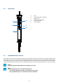
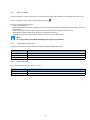
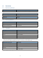
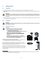
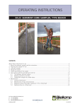
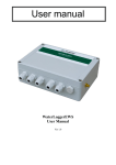
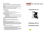
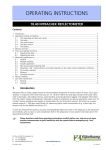
Global Data Transmitter Single GPRS/UMTS User manual (original instructions) All it takes for environmental research P.O. Box 4, 6987 ZG Giesbeek, the Netherlands © 2014-08 T F +31 313 88 02 00 +31 313 88 02 99 [email protected] I www.eijkelkamp.com M4.11.33.01.E Table of contents 1 Introduction .................................................................................................................................................................................................4 1.1 How to use this manual ......................................................................................................................................................................4 1.2 Original instructions ............................................................................................................................................................................4 1.3 Working principle .................................................................................................................................................................................4 1.3.1e-SENSE system...............................................................................................................................................................................4 1.3.2 Data communication overview ................................................................................................................................................4 1.3.3Communication intervals ...........................................................................................................................................................5 1.3.4Modem ..............................................................................................................................................................................................6 1.3.5 GDT Server ........................................................................................................................................................................................6 1.3.6 Eijkelkamp Web Portal .................................................................................................................................................................6 1.3.7E-mail functionality .......................................................................................................................................................................7 1.4 Service and support .............................................................................................................................................................................7 1.4.1Qualified personnel .......................................................................................................................................................................7 1.4.2Contact details ................................................................................................................................................................................7 2 Safety .................................................................................................................................................................................................8 2.1 Symbols in the manual .......................................................................................................................................................................8 2.2 Intended use ...........................................................................................................................................................................................8 2.3 Qualification of the user .....................................................................................................................................................................8 2.4 Liability .................................................................................................................................................................................................8 2.5 Regulations and instructions ............................................................................................................................................................9 2.5.1Modem ..............................................................................................................................................................................................9 2.5.2Battery pack .....................................................................................................................................................................................9 2.5.3Connection .......................................................................................................................................................................................9 2.6 Environment and disposal of waste ............................................................................................................................................ 10 2.6.1 Correct disposal of the product ............................................................................................................................................. 10 2.6.2 Correct disposal of the battery pack .................................................................................................................................... 10 3 Product overview ............................................................................................................................................................................................ 11 3.1 Outside view ........................................................................................................................................................................................ 11 3.2 Inside view ........................................................................................................................................................................................... 12 3.3 Explanation of the controls ............................................................................................................................................................ 12 3.3.1Service button .............................................................................................................................................................................. 13 3.3.2 Connection LED (green) ........................................................................................................................................................... 13 3.3.3 Error LED (red)............................................................................................................................................................................... 13 3.4 Technical data ..................................................................................................................................................................................... 14 3.4.1Mechanical specifications ........................................................................................................................................................ 14 3.4.2Electrical specifications ............................................................................................................................................................. 14 3.4.3Connections .................................................................................................................................................................................. 14 3.4.4Ambient conditions ................................................................................................................................................................... 15 3.4.5Certifications ................................................................................................................................................................................. 15 4 Getting started .............................................................................................................................................................................................. 16 4.1 Unpacking ............................................................................................................................................................................................ 16 4.2 Installation ............................................................................................................................................................................................ 16 4.2.1 Mounting the modem .............................................................................................................................................................. 16 4.2.2 Connecting the antenna .......................................................................................................................................................... 17 4.2.3 Connecting the sensor cable .................................................................................................................................................. 17 4.3 Commissioning ................................................................................................................................................................................... 18 5 Maintenance .............................................................................................................................................................................................. 18 5.1 Preparation .......................................................................................................................................................................................... 18 5.2 General inspection overview ......................................................................................................................................................... 18 5.3 Inspection and cleaning .................................................................................................................................................................. 19 5.3.1 Inspecting and cleaning the outside of the modem .................................................................................................... 19 5.3.2 Dismounting the modem ........................................................................................................................................................ 19 M4.11.33.01.E 2 5.3.3 Opening the enclosure ............................................................................................................................................................. 19 5.3.4 Inspecting and cleaning the inside of the modem......................................................................................................... 20 5.3.5 Replacing the desiccant bag ................................................................................................................................................... 20 5.3.6 Closing the enclosure ................................................................................................................................................................ 21 5.3.7 Mounting the modem................................................................................................................................................................ 21 5.4 (Re-)placing the battery pack ........................................................................................................................................................ 21 5.5 (Re-)placing the SIM card (optional) ........................................................................................................................................... 22 5.6 Storage .............................................................................................................................................................................................. 22 6 Specifications .............................................................................................................................................................................................. 23 6.1 Parts list .............................................................................................................................................................................................. 23 7 Declaration of Conformity ............................................................................................................................................................................ 24 7.1 EC Declaration GSM / GPRS ............................................................................................................................................................ 24 7.2 EC Declaration UMTS ........................................................................................................................................................................ 25 Disclaimer Nothing from this document may be copied and/or made public by means of printing, photocopy, microfilm or in any other way without the prior written approval of the publisher. Technical data can change without prior notification. Eijkelkamp Agrisearch Equipment is not responsible and/or liable for any damage and/or personal injury due to (incorrect) use of this product. Eijkelkamp Agrisearch Equipment would be pleased to receive your reactions and comments about this product and the user instructions. 3 M4.11.33.01.E 1Introduction 1.1 How to use this manual This manual is intended as a reference manual by which users can use and configure the Global Data Transmitter Single GPRS (or Global Data Transmitter Single UMTS), henceforth called the modem. Make sure you have read and understood the manual before you use the modem. For an overview of the modem and its components, refer to chapter 3. Make sure that you: • know the contents of this manual; • follow up all directions; • do not change the sequence of the procedures. 1.2 Original instructions The original instructions for this manual have been written in English. Other language versions of this manual are a translation of the original instructions. 1.3 Working principle 1.3.1 e-SENSE system The purpose of the e-SENSE system is to collect data of measurements in the field. The e-SENSE system works by means of a wireless data connection to the GSM network (GPRS or UMTS1). The data connection is encrypted to prevent unwanted access. The e-SENSE system consists of sensors (e+ loggers and/or Divers), the modem, and the GDT Server. The communication between these devices and their function will be discussed in the following sections. 1.3.2 Data communication overview A B E BACK GDT OFFICE SERVER D MODEM E SENSOR SENSOR F F C G H A Eijkelkamp Web Portal BE-mail C SMS alarm D GSM Network E Sensor cable F Sensor measurement G Send interval H Wake-up interval I Measurement interval 1. UMTS is optional. M4.11.33.01.E 4 I Device / tool Communication Activity Sensor Sensor cable • perform the measurements • store data Modem Sensor cable GSM (UMTS is optional) • intermediates between the GDT Server and the sensor • communicates with the GDT Server • the internal barometer measures the air pressure and temperature 1.3.4 GDT Server GSM (UMTS is optional) • communicates with the modem and its connected sensor • collects and stores data • configures the modem and sensor settings 1.3.5 Eijkelkamp Web Portal E-mail Internet • user can configure modem and sensor settings • receives data from the GDT Server • user can view the status of the modem and sensor 1.3.6 and 1.3.7 1.3.3 Refer to Communication intervals The following figure shows an example of how the various communication intervals between the devices can be arranged. A Measurement interval of sensor 1 B Wake-up interval C Measurement interval of internal Barometer (not modifiable) D Send interval A B C BD CE D F Measurement interval A measurement interval is the interval between two sensor measurements of a sensor. The measurement interval can be adjusted. Wake-up interval The wake-up interval is the frequency in which the modem starts up (wakes up from sleep mode) to intermediate between the GDT Server and the connected sensor. Note SMS messages are only sent in case of an alarm situation (and hence not in a specific interval). Send interval The send interval is the frequency with which the GDT Server sends the new data to the user or the Eijkelkamp Web Portal. 5 M4.11.33.01.E 1.3.4Modem For an overview of the modem and its components, refer to chapter 3. The modem is the connecting element between the sensor and the GDT Server in the e-SENSE system. The modem is designed to obtain measurement data from a central location without having to travel to the location(s) where the sensors are placed. The modem will periodically become active at wake-up intervals and log into the GDT Server. The most important functions of the modem are: • Transporting sensor data of the connected sensor to the GDT Server; • Enabling remote monitoring and control of the connected sensor. The most important features of the modem are: • No software needed; • Global connectivity; • Easy ‘plug-and-play’ installation; • Internal barometer; • One sensor can be connected (for multiple sensor connection use the GDT Multiple) There are two methods to get access to the modem. The following table gives an overview. Option Tool Refer to Eijkelkamp Web Portal Web browser Online manual on Eijkelkamp Web Portal E-mail functionality E-mail addresses Supplement 2 (M2.11.32.01.02.E) 1.3.5 GDT Server The GDT Server is designed to control the modem and its connected sensor. The following table gives an overview. Type of control Specification Communication Collecting data at wake-up intervals Monitoring Checking the status Configuration Changing the settings Alarming Sending an e-mail and/or SMS notification in case the userdefined or predefined limits are exceeded 1.3.6 Eijkelkamp Web Portal The webportal is designed to give easy access to the GDT Server. The web portal: • Gives quick access to the data; • Has a user-friendly interface to configure the modem and sensor settings. Requirements: • Internet access; • Web browser; • User account to log into the Eijkelkamp Web Portal. Note Refer to the online manual on the Eijkelkamp Web Portal for detailed information on how to use the web portal. M4.11.33.01.E 6 1.3.7 E-mail functionality The user can communicate with the modem by sending an e-mail to the GDT Server. The e-mail interface is meant for advanced users of the modem. Requirements: • Internet • A user e-mail address • A modem e-mail address Note Refer to Supplement 2 for detailed information on how to use the e-mail functionality. 1.4 Service and support 1.4.1 Qualified personnel Eijkelkamp maintains a staff of experienced service personnel. Their expert knowledge could be of assistance at inspection, installation, or repair activities. For information with respect to specific adjustments, installation, maintenance or repair jobs, which fall beyond the scope of this manual, contact Eijkelkamp. Make sure you have the following data at hand: • Product code2 • Date of manufacture • Serial number • Date of purchase • Invoice number 1.4.2 Contact details The address and contact details can also be found on the front of this manual. Eijkelkamp Agrisearch Equipment BV Nijverheidsstraat 30 P.O. Box 4, 6987 ZG Giesbeek The Netherlands Telephone Fax E-mail Internet +31 313 88 02 00 +31 313 88 02 99 [email protected] www.eijkelkamp.com 2. The product code can be found in the footer of every page. The product code starts with an M. 7 M4.11.33.01.E 2Safety 2.1 Symbols in the manual WARNING ‘Warning’ identifies a hazard that could lead to personal injury, including death. CAUTION ‘Caution’ identifies a hazard that could lead to damage to the machine, damage to other equipment and/ or environmental pollution. Note ‘Note’ is used to highlight additional information. 2.2 Intended use The modem is designed to communicate with a sensor (e+ logger or Diver) in the field. The modem has 1 sensor port, so only 1 sensor can be connected to the modem. The user can configure the modem according to his/her own wishes, for instance regarding measurement interval. CAUTION The modem has class IP67 protection. This means the modem is dust protected and resistant against temporary immersion. The temporary immersion must not exceed 30 minutes, at a maximum of 1 meter under water. Do not continuously submerge in water. When there is water inside the enclosure, contact Eijkelkamp. CAUTION Every other or further use is not in conformance with the intended use. 2.3 Qualification of the user The user should have a general knowledge about the use of a computer system and computer programs. For the basic maintenance work a general technical background is required. 2.4Liability The modem is delivered factory sealed with IP67 protection class. CAUTION We prefer not to open the modem in the field. Only open the modem in a clean and dry environment. Avoid unnecessary opening of the modem. The IP67 protection class can only be preserved and guaranteed when the following parts are clean, dust-free and undamaged: • enclosure; • sealing of the enclosure; • protection caps; • connector. Furthermore, make sure that: • The sensor cable is correctly connected. Refer to 4.2.3. • The modem is mounted correctly in the monitoring well. Refer to 4.2.1. • The work is performed according to the local ESD safety regulations. • Only original Eijkelkamp parts are used. M4.11.33.01.E 8 2.5 Regulations and instructions 2.5.1Modem WARNING • Do not use the modem when it is wet or moisty inside the enclosure. • Dry a wet or moisty modem with a dry, lint-free cloth. Do not dry the modem in any other way. Note Never take a battery pack or a modem with an installed battery pack with you as luggage during a flight. Due to severe civil aviation regulations (class 9 dangerous goods), it is forbidden to take a battery pack with you during a flight. The battery pack, or modem with battery pack enclosed, should be officially packaged with the necessary certificates and send by air cargo. Make sure that you comply with the aviation regulations. 2.5.2 Battery pack The battery pack contains Lithium metal batteries. These batteries have a high energy density so they must be handled with care. Incorrect usage could lead to overheating and explosion. WARNING • Do not use a damaged battery pack. • Keep the battery pack away from fire or heating source. • Do not submerge the battery pack in water. • Always use the correct battery pack. Only use original parts. • Do not short circuit the battery pack. • Do not charge the battery pack. Note Never take a battery pack or a modem with an installed battery pack with you as luggage during a flight. Due to severe civil aviation regulations (class 9 dangerous goods), it is forbidden to take a battery pack with you during a flight. The battery pack, or modem with battery pack enclosed, should be officially packaged with the necessary certificates and send by air cargo. Make sure that you comply with the aviation regulations. 2.5.3Connection WARNING Do not use worn and/or damaged cables. 9 M4.11.33.01.E 2.6 Environment and disposal of waste CAUTION Always observe the local rules and regulations with respect to processing or disposing of (non-reusable) parts. CAUTION Always first remove the battery pack. Refer to 5.4. For correct disposal of the battery pack, refer to 2.6.2. 2.6.1 Correct disposal of the product WARNING Do not dispose with other types of waste! This could possibly cause harm to the human health or the environment. If worn, damaged or not necessary anymore, please return the modem to your local dealer for correct disposal or repair. 2.6.2 Correct disposal of the battery pack WARNING Do not dispose with other types of waste! The battery pack contains substances that can cause harm to the human health or the environment. To protect natural resources and promote material reuse, separate batteries from other types of waste and recycle them through your local battery return system. If not possible, return the battery pack to your local dealer. CAUTION Never return the battery pack to the local dealer by air transport because the battery pack contains lithium. M4.11.33.01.E 10 3 Product overview 3.1 Outside view A G H D C F B E A Antenna connector3 B 1 sensor port3 (5-pin male connector, A-coded) C Enclosure D Top cap E Service button F Connection LED G Error LED H IRDA connection I Sensor cable JVent J I CAUTION The modem has class IP67 protection. This means the modem is dust protected and resistant against temporary immersion. The temporary immersion must not exceed 30 minutes, at a maximum of 1 meter under water. Do not continuously submerge in water. When there is water inside the enclosure, contact Eijkelkamp. 3 Including a waterproof protection cap 11 3.2 Inside view F B A E D APCB B SIM card (in SIM card holder) C Battery pack D Battery pack connector E Sensor connector F Desiccant bag C 3.3 Explanation of the controls The controls consist of a service button and two LEDs (connection and error) on the left and an IRDA interface on the right. Refer to 3.3.2 and 3.3.3 for the explanation of the LEDs. After the service button is pressed, the LEDs show the status of the modem after the connection has been established (or if it has failed). To save energy, the LEDs will be automatically disabled after about 15 seconds once a successful connection has been established, or after an error has occurred. Note The LEDs are always OFF until the service button is pressed. Note When the battery pack is connected to the modem: • The modem will behave as if the service button was pressed; • The green LED will go on to indicate the modem is powered. 12 3.3.1 Service button The Service button is used to initially turn on the modem and afterwards to establish a connection to the GDT Server. The Service button can be recognised by the following icon When the service button is pressed: • The green LED will go on. • If the modem is connected to a computer by means of an IRDA connection, the modem will immediately connect to the computer. • If there is no IRDA connection within 20 seconds the modem starts to connect to the GDT Server. • While connecting to the GDT Server the green and red LED are blinking. • When all the data is transmitted between GDT-S and GDT Server the LEDs are off. Note It is not possible to turn off the modem by pressing the service button. 3.3.2 Connection LED (green) The green Connection LED shows the status of the connection with the GDT Server. Description Blinking (green) The modem is busy connecting to the GDT Server. ON (green) The modem is connected to the GDT Server. OFF The modem is not connected to the GDT Server. 3.3.3 Error LED (red) The red Error LED indicates that there is an error. Description Blinking (red) An error occured. OFF There are no errors. 13 3.4 Technical data 3.4.1 Mechanical specifications Specification Dimensions Enclosure 0 enclosure 48.3 mm, 0 top cap 60 mm, length 340 mm Specification Weight GDT-S (incl. battery pack) approx. 1750 g Specification Materials Enclosure Stainless steel 304, top cap POM (synthetic material) 3.4.2 Electrical specifications Item Specification Battery pack (internal) 7.2 V (Lithium metal) Life time of the battery pack 3 years (at a 1 hour interval) Maximum rated power usage 4.32 W (600 mA) Modem time accuracy better than 1 minute/day 3.4.3Connections Messaging Specification Message mode web portal, e-mail, SMS alarm, other GSM Quad band type (850, 900, 1800, 1900 MHz) UMTS (optional) 2100 MHz SIM card Vodafone NL M2M * Antenna connector FME connector Sensor port 5-pin male connector, A-coded IRDA Read out by IRDA dongle * SIM card exchangeable by the user. The functionality of SIM cards other than Vodafone M2M is guaranteed only after the functionality tests are fulfilled by Eijkelkamp. Therefore it is advised to use tested SIM cards only. Integrated barometer sensor Specification Barometer measuring range 10 ... 1200 mbar * Resolution 0.01 mbar Accuracy barometer ± 2 mbar (at 300 ... 1100 mbar, 0 ...50 °C Temperature measuring range -40 ... +85 °C Resolution 0.01 °C Accuracy temperature ± 0.8 °C (at 25 °C) ± 2.0 °C (0 ... 50 °C) * 1 mbar is approximately 1 cmH2O 14 Antenna * Specification GSM (external) Quad band type (850, 900, 1800, 1900 MHz) UMTS (optional) 2100 MHz Connector FME Bulkhead Ingress Protection IP67 or better * Other antenna types are available on request. Sensor ports Specification Number of sensor ports 2 Port 1 (external) sensor (e+ logger or Diver) via sensor cable Port 2 (internal) integrated barometer and temperature sensor 3.4.4 Ambient conditions Item Specification Temperature -20 ... +50 °C Ingression protection (enclosure) UMTS (optional) IP67 (30 min.@1mH2O) Max. operation height 2000 m 3.4.5Certifications Item Specification CE CE compliant EMC / ESD EN 61000-6-1, EN 61000-6-3 15 4 Getting started 4.1 Unpacking 1. When unpacking, carefully follow the instructions as given on the packaging or on the product. 2. Check that your delivery is correct and complete. Refer to the order list and the delivery list. If incomplete, contact Eijkelkamp. CAUTION Depending on the destination of the order, the modem is pre-installed with SIM card and battery pack. It is not necessary to open the modem. Avoid unnecessary opening of the modem because of the risk of leakage. 3. Check the delivery for any transport damage. Report any damage immediately by filing a claim against the carrier and mark the bill of lading accordingly. 4.2 Installation CAUTION The guarantee will be void when the modem is not used for its intended use and/or at incorrect installation. Refer to 2.2 and 4.2. 4.2.1 Mounting the modem CAUTION • Place the modem in a protective environment.4 • Do not expose the modem to direct sunlight. • Avoid deformation of the enclosure. - Do not use too much force when mounting the modem. • Keep the Service button free from pressure. • The connector should be easily reachable and there should be enough space to connect the cable to the connector. • All parts must be clean and dry prior to installation. • Do not expose the modem to vibration, direct heat sources and/or forms of radiation and magnetism. We distinguish two installation methods, namely; 1. Directly in the monitoring well, e.g. finished with a street cover (A) or 2. In a monitoring well that is installed in a well cover (B) The modem is fitted with a robust external antenna (art. no. 11.31.34). The external antenna is intended to be installed on the cover of the well cover or with the mounting plate (D) in the street cover. A B C D Adjust the universal monitoring well adapter ring (C) to your monitoring well so that the modem hangs correctly in the monitoring well. Then connect the sensor cable to the modem. Install sensor, sensor cable and modem into the well cover. 4. If the protective environment is air-tight, the internal barometer data cannot be used. In this case, use the data of another barometer location or external Baro Diver. 16 4.2.2 Connecting the antenna CAUTION All parts must be clean and dry prior to installation. 1. Mount the antenna. Refer to the installation instructions of your specific antenna. CAUTION Do not use force. 4.2.3 Connecting the sensor cable CAUTION All parts must be clean and dry prior to installation. 1. Connect the sensor cable to the sensor port (A). CAUTION Do not use force. There is only one way to connect the cable to the sensor port. Always check the position of the positioning cam (B). A 2. Slide the safety cord over (C) the sensor connector (D). 3. Install the sensor cable connector, pay attention to the postioning cam (B). 4. Fasten the sensor cable by turning the locking ring clockwise. CAUTION Do not fasten the cable too tight onto the connector. Use your thumb and index finger. For an internally clean connector, the IP67 protection class is guaranteed at a torque of 0.6 Nm. 5. Click the safety cord in the safety ring (E). C D E 17 B 4.3Commissioning A B C D A Error LED (red) Connection LED (green) IRDA connection Service button C 1. Press the service button (D). The connection LED (B) will go on. Note The LED should go ON. Refer to 3.3 to see which status the LEDs indicate. B The GDT Server will activate the connected sensor. D 2. If commissioning is OK the green LED goes off. 5Maintenance 5.1 Preparation CAUTION Only original parts must be used, otherwise the guarantee will be void. Make sure you take with you the following tools and accessories: • Crosshead screwdriver (PZ-2 Pozi); • Cloth (clean, dry and lint-free); • Replacement desiccant kit. Refer to 6.1. • Replacement battery pack. Refer to 6.1. • Replacement SIM card (optional). • Replacement antenna. • Replacement cable and sensor. 5.2 General inspection overview The modem requires little maintenance. However, if you need to do maintenance work, always check the following points during maintenance. Note It is advised always to take a replacement battery pack with you. Check the battery capacity level beforehand via the Eijkelkamp Web Portal or the e-mail functionality. Refer to the Online Manual or to Supplement 2 on how to check the battery capacity level. Note Never take a battery pack or a modem with an installed battery pack with you as luggage during a flight. Due to severe civil aviation regulations (class 9 dangerous goods), it is forbidden to take a battery pack with you during a flight. Inspection Check Action (if required) Enclosure (external) Dirt / Humidity Clean and dry with a dry, lint-free cloth. Enclosure (internal) Humidity Replace the desiccant kit. Refer to 5.3.6. If wet or moisty, contact Eijkelkamp. 18 Inspection Check Action (if required) Sensor cable Wear or damage Replace the cable. Antenna Wear or damage Replace the antenna. SIM card 5.3 Refer to 5.5 Inspection and cleaning We advise you to take the necessary ESD safety regulations and to apply new vaseline to the O-rings in the cap seal of the modem during assembly (replace o-rings when damaged). 5.3.1 Inspecting and cleaning the outside of the modem 1. Check the outside of the modem for dirt and humidity. Pay special attention to the vent. The vent has to be free of dirt. Never use sharp tools to clean. 2. Clean and dry the modem with a dry, lint-free cloth. 5.3.2 Dismounting the modem Note If you need to open the enclosure, it is advised to remove the modem, so the modem can be taken to a clean and dry environment. 1. 2. 3. 4. 5. Check if the cable and connector are still connected correctly. Also check the cable and connector for possible defects. Disconnect the antenna from the antenna connector. Turn the hexagon locking counter clockwise. Disconnect the sensor cable from the sensor port. Turn the hexagon locking counter clockwise. Clean the antenna connector and sensor port with a dry, lint-free cloth. Take the modem to a clean and dry environment. 5.3.3 Opening the enclosure CAUTION Do not open the modem in the field. Only open the modem in a clean and dry environment. Note It is advised not to open the enclosure unless it is really necessary (e.g. for placing / replacing the batteries). Opening the enclosure increases the risk of leakage afterwards. 1. Loosen the two screws (turning counter clockwise) and carefully push the top cap out of the housing. 19 5.3.4 Inspecting and cleaning the inside of the modem 1. Check the inside of the modem for dirt, dust, humidity and damage. Pay special attention to the sealings of the top cap, the sealing rings must be free of dirt, undamaged and not-twisted. WARNING The modem must be free from dirt, dust, humidity and damage. Only clean the seal and flash ridge with a clean lint-free cloth if necessary. Never touch the electronics of the printed circuit board (PCB)! CAUTION Do not use greasy substances (except for o-rings) and agents, such as white spirit, acetone or thinner. 5.3.5 Replacing the desiccant bag CAUTION Only use original parts. A new desiccant kit can be ordered at Eijkelkamp. Refer to 6.1. CAUTION Work only in a dry environment, try to act quickly during the replacing of the desiccant bag! 1. Remove the 3-way battery connector and disconnect the 5-way sensor connector. 2. Carefully fold the protective mesh sleeve (A) back sufficiently to expose half the length. A CAUTION Never remove the protective mesh sleeve from the printed circuit board! 3. Remove the old desiccant bag carefully and check whether this bag is excessively wet. If this is the case, this could be an indication of leakage. Please contact Eijkelkamp service department. CAUTION The new desiccant bag (B) must be taken out of its package at the last moment. It must be protected against all kinds of moisture before it is placed in the dry enclosure of the modem. B A 4. Carefully fold the protective mesh sleeve (A) back. 6. If it is not necessary to replace the battery pack , close the enclosure immediately. See 5.3.6. 20 5.3.6 Closing the enclosure 1. Connect the 3-way connector to the battery and replace the battery. 2. Check whether the O-rings are clean and undamaged. 3. Check whether the top cap with the O-rings is dirt-free, along with the sealing surface in the housing tube. 4. If no grease is visible on the surfaces, apply a thin layer of acid-free vaseline (prevent dirt, work clean). 5. Turn the top cap with the modem circuit and battery a half to a complete revolution to take up the coiled cable (if necessary). This may be done in either direction. 6. Carefully slide the modem back into the housing tube and press the top cap into the housing with a light turning movement. Take note of the holes for the screws. 7. Turn the two screws in hand tight. Use a crosshead screwdriver (PZ-2 Pozi). Refer to 5.1. 5.3.7 1. 2. 3. 4. Mounting the modem Connect the antenna to the antenna connector. Refer to 4.2.2. Connect the sensor cable to the sensor port. Refer to 4.2.3. Re-install the modem in the monitoring well or well cover. Start the commissioning process. Refer to 4.3. 5.4 (Re-)placing the battery pack On receipt of a ‘low battery’ alarm, the battery must be replaced along with the desiccant bag. We advise you to take the necessary ESD safety regulations and to apply new vaseline to the O-rings in the cap seal of the modem during assembly (replace o-rings when damaged). Note Use original parts. A new battery pack can be ordered at Eijkelkamp. Refer to 6.1. 1. Follow all procedures of 5.3.1 to 5.3.5. 2. Disconnect the 3-way battery connector (A). CAUTION Work according to your local ESD safety regulations. Avoid touching the printed circuit board (PCB). Note All setting changes that have not yet been saved will be lost when the battery pack is disconnected. 3. Carefully remove the empty battery pack. 4. Place the replacement battery pack. CAUTION Prevent contact between the battery pack and the PCB. Note Make sure the battery pack is placed in the correct position. Refer to the figure. The battery connector must easily reach the connector on the modem. 21 5. Connect the battery connector. Note When the battery pack is connected to the modem: • The modem will behave as if the service button was pressed; • All LEDs will briefly go on to indicate the modem is powered. 6. Follow all procedures of 5.3.6 to 5.3.7. 7. Dispose of the old battery pack in a proper way. Refer to 2.6.2. 5.5 B (Re-)placing the SIM card (optional) A WARNING Always disconnect the battery pack before replacing the SIM card. 1 2 3 4 5 CAUTION Make sure that the PIN code of the SIM card is turned off or set to the desired PIN code. Note If a PIN code is used, make sure that the PIN code that was configured in the modem is identical to the PIN code of the SIM card. 1. Follow all procedures of 5.3.1 to 5.3.5. 2. Disconnect the battery connector. Refer to 5.4 3. Slide the holder in the open position. Refer to step 1 in the figure. 4. Pull up the holder. Refer to step 2 in the figure. 5. Remove the SIM card from the holder. Refer to step 2 in the figure. 6. Place the new SIM card into the holder. Refer to step 4 in the figure. 7. Push back the holder. Refer to step 4 in the figure. 8. Slide the holder in the closed position. Refer to step 5 in the figure. 9. Connect the battery connector. Refer to 5.4. 10. Follow all procedures of 5.3.6 to 5.3.8. 5.6Storage CAUTION Do not place the modem in a humid and dusty environment. Do not place any heavy materials on top of the modem. 1. Clean the outside of the modem. Refer to 5.3.1. 2. Dismount the modem. Refer to 5.3.2. 3. Store the modem in a clean and dry place. Note If a modem is not to be used for a longer period of time, it is important that the modem will be set in the power OFF mode via the Eijkelkamp Web Portal or e-mail functionality. Refer to online manual on Eijkelkamp Web Portal or Supplement 2 on how to put the modem in the power OFF mode. In case the modem will not be used for very long period of time, it is also advised to disconnect the battery pack. Even if the modem is in the power OFF mode, it actually continues to draw a minimum amount of current and thus drains the battery. However, it is also advised not to open the enclosure of the modem unless you really need to do so. Opening the enclosure increases the risk of leakage afterwards. Consider whether the battery pack needs to be disconnected or not. If the battery pack needs to be disconnected, refer to step 1 and 2 of 5.4. 22 6Specifications 6.1 Parts list CAUTION Only original parts must be used, otherwise the guarantee will be void. Article number Part name 11.33.01 Global Data Transmitter Single (GDT-S) GSM/GPRS 11.33.02 Global Data Transmitter Single UMTS 11.33.25 Battery pack GDT-S 11.31.34 Robust external antenna 11.31.37 External antenna with optimal signal strength 11.31.34.01 Antenna mounting plate 11.31.35 Adaptor ring GDT-S nn.nn.nn Battery-pack with spare parts 11.62.01 SIM card (The Netherlands) 11.62.02 SIM card (Europe zone) 11.62.02.01 SIM card (Rest of the World zone) 23 7 Declaration of Conformity 7.1 EC Declaration GSM / GPRS EC Declaration of Conformity* The undersigned, representing the manufacturer: Eijkelkamp Agrisearch Equipment BV Nijverheidsstraat 30 6987 EM Giesbeek The Netherlands Herewith declare that the product: Type: Art.nr.: Function(s): Global Data Transmitter Single (Quad-Band GSM/ GPRS) 11.33.01 connecting element between sensor (e+-logger or diver) and the GDT Server in the e-SENSE system. The most important functions of the modem: Passing through the collected data of the connected sensor to the GDT Server; Enabling remote monitoring of the connected sensor. is in conformity with the essential requirements of the following EC Directive(s) when installed in accordance with the installation instructions contained in the product documentation: a) b) c) d) 2014/30/EU EMC Directive 1999/5/EC R&TTE (applies only the GSM/ GPRS module; Cinterion Wireless Module TC63i) 2012/19/EU Waste Electrical and Electronic Equipment (WEEE) 2011/65/EU RoHS Directive and that the standards and/or technical specifications referenced below have been applied: a) EMC-Directive: EN 61326-1:2013 Electrical equipment for measurement, control and laboratory use - EMC requirements - General requirements EN 55011:2009/ A1:2010 EN 61000-4-2:2009 EN 61000-4-3:2006/ A1:2008/ A2:2010 EN 61000-4-4:2012 EN 61000-4-6:2009 EN 61000-4-8:2010 b) Industrial, scientific and medical equipment -Radio-frequency disturbance characteristics - Limits and methods of measurement Electrostatic discharge (ESD) immunity test Radiated, radio-frequency, electromagnetic field immunity test Electrical fast transient (EFT)/ burst immunity test Immunity to conducted disturbances, induced by radio-frequency fields Power frequency magnetic field immunity test R&TTE Directive: (applies only the GSM/ GPRS module; Cinterion Wireless Module TC63i) EN 301 489-1 V1.9.2 Electromagnetic compatibility and Radio spectrum Matters (ERM); ElectroMagnetic Compatibility (EMC) standard for radio equipment and services; Part 1: Common technical requirements EN 301 489-7 V1.3.1 Electromagnetic compatibility and Radio spectrum Matters (ERM); ElectroMagnetic Compatibility (EMC) standard for radio equipment and services; Part 7: Specific conditions for mobile and portable radio and ancillary equipment of digital cellular radio telecommunications systems (GSM and DCS) EN 301 511 V9.0.2 Global System for Mobile communications (GSM); Harmonized EN for mobile stations in the GSM 900 and GSM 1800 bands covering essential requirements under article 3.2 of the R&TTE directive (1999/5/EC) Giesbeek, 14-Aug.-2014 Manufacturer: Signature Frank Tillmann Managing Director 24 7.2 EC Declaration UMTS EC Declaration of Conformity* The undersigned, representing the manufacturer: Eijkelkamp Agrisearch Equipment BV Nijverheidsstraat 30 6987 EM Giesbeek The Netherlands Herewith declare that the product: Type: Art.nr.: Function(s): Global Data Transmitter Single (UMTS; Five-Band 3G) 11.33.02 connecting element between sensor (e+-logger or diver) and the GDT Server in the e-SENSE system. The most important functions of the modem: Passing through the collected data of the connected sensor to the GDT Server; Enabling remote monitoring of the connected sensor. is in conformity with the essential requirements of the following EC Directive(s) when installed in accordance with the installation instructions contained in the product documentation: a) b) c) d) 2014/30/EU EMC Directive 1999/5/EC R&TTE (applies only the UMTS module; Cinterion Wireless Module PH8) 2012/19/EU Waste Electrical and Electronic Equipment (WEEE) 2011/65/EU RoHS Directive and that the standards and/or technical specifications referenced below have been applied: a) EMC-Directive: EN 61326-1:2013 Electrical equipment for measurement, control and laboratory use - EMC requirements - General requirements EN 55011:2009/ A1:2010 EN 61000-4-2:2009 EN 61000-4-3:2006/ A1:2008/ A2:2010 EN 61000-4-4:2012 EN 61000-4-6:2009 EN 61000-4-8:2010 b) Industrial, scientific and medical equipment -Radio-frequency disturbance characteristics - Limits and methods of measurement Electrostatic discharge (ESD) immunity test Radiated, radio-frequency, electromagnetic field immunity test Electrical fast transient (EFT)/ burst immunity test Immunity to conducted disturbances, induced by radio-frequency fields Power frequency magnetic field immunity test R&TTE Directive: (applies only the UMTS module; Cinterion Wireless Module PH8) EN 300 440-2 V1.4.1 Electromagnetic compatibility and Radio spectrum Matters (ERM); Short range devices; Radio equipment to be used in the 1 GHz to 40 GHz frequency range; Part 2: Harmonized EN covering the essential requirements of article 3.2 of the R&TTE Directive EN 301 489-1 V1.9.2 Electromagnetic compatibility and Radio spectrum Matters (ERM); ElectroMagnetic Compatibility (EMC) standard for radio equipment and services; Part 1: Common technical requirements EN 301 489-3 V1.4.1 Electromagnetic compatibility and Radio spectrum Matters (ERM); ElectroMagnetic Compatibility (EMC) standard for radio equipment and services; Part 3: Specific conditions for Short-Range Devices (SRD) operating on frequencies between 9 kHz and 40 GHz EN 301 489-7 V1.3.1 Electromagnetic compatibility and Radio spectrum Matters (ERM); ElectroMagnetic Compatibility (EMC) standard for radio equipment and services; Part 7: Specific conditions for mobile and portable radio and ancillary equipment of digital cellular radio telecommunications systems (GSM and DCS) EN 301 489-24 V1.5.1 Electromagnetic compatibility and Radio spectrum Matters (ERM); ElectroMagnetic Compatibility (EMC) standard for radio equipment and services; Part 24:Specific conditions for IMT-2000 CDMA Direct Spread (UTRA and E-UTRA) for Mobile and portable (UE) radio and ancillary equipment EN 301 511 V9.0.2 Global System for Mobile communications (GSM); Harmonized EN for mobile stations in the GSM 900 and GSM 1800 bands covering essential requirements under article 3.2 of the R&TTE directive (1999/5/EC) EN 301 908-1 V5.2.1 IMT cellular networks; Harmonized EN covering the essential requirements of article 3.2 of the R&TTE Directive; Part 1: Introduction and common requirements EN 301 908-2 V5.2.1 IMT cellular networks; Harmonized EN covering the essential requirements of article 3.2 of the R&TTE Directive; Part 2: CDMA Direct Spread (UTRA FDD) User Equipment (UE) Giesbeek, 14-Aug.-2014 Manufacturer: Signature Frank Tillmann Managing Director *: This declaration relates exclusively to the machinery in the state in which it was placed on the market and excludes components which are added and/or operations carried out subsequently by the final user. 25