1
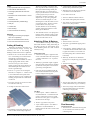
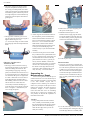
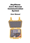
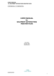
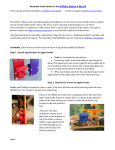
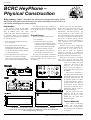
CAVE RADIO
BCRC HeyPhone –
Physical Construction
Brian Jopling, “Jopo”, describes the mechanical design philosophy for the
HeyPhone and gives some instruction for those intending to build a unit or to
use similar techniques for other projects.
Introduction
The electronic design of the BCRC
HeyPhone has already been published (Hey,
2000 & Bedford 2001). This article
completes the public domain documentation
by providing details of the mechanical
construction. The information presented here
serves three purposes:
• It will provide the information necessary
for servicing units.
• It will enable rescue teams who need
additional units after the end of the
official BCRC production run is complete,
to build units which are virtually identical
to a genuine HeyPhone.
• In providing details of the constructional
techniques it will assist those building
other cave-proof electronic equipment
who are unable to find suitable enclosures.
It is important that people intending to
build a HeyPhone read a statement released
by the BCRC which will be printed in the
next issue.
Overall Design
The aim was to produce a box which:
• was watertight;
• separated the transceiver from the
control box so that the damage-prone
components such as switches could be
replaced without interfering with the
more delicate electronic circuitry;
• could be fitted into a Peli 1200 case,
Daren drum or a small ammo box.
We could not find suitable commercial
boxes and having custom made diecast boxes
made was found to be very expensive given
the quantities.
Having spent some time prototyping, I
decided that using gaskets and screw lids
would be very difficult to achieve without
sophisticated – and hence expensive – jigs
for such a small run. It then occurred to me
that if we bonded the separate parts together
we would avoid gaskets and make the box
less prone to inquisitive opening, but still
reasonably easy to open for maintenance or
repair. I chose PVC as it is nice to machine
and easily solvent welded.
Basically we have three components:
1. A top box for the controls, terminated at a
D-type socket; 2. A top plate to carry a
D-type plug to which the transceiver
electronics is attached; 3. A bottom box.
Effectively, the top plate forms the bottom of
the top box and the top of the bottom box.
Both boxes are basically a rectangular
sheet “vee’d” along the fold lines, heatfolded, tack-bonded and a pillar fitted in each
corner to give rigidity and a good
corner seal. The pillars in the
transceiver box are solid with
those in the top box drilled as a
screw guide (with an extra pair in
the middle).
The boxes are separated by a
PVC plate which forms the barrier
between the top (control) box and
the bottom (transceiver) box and
to which the control box is fitted.
A waterproofed D-type socket in
the plate connects the controls to
the transceiver. On the underside
of the plate are bonded six 4mm ×
6mm∅ PVC buttons which are
blind drilled and taped.
The plate is kept level in the
transceiver box by the corner
pillars and four strips of PVC
bonded onto the inside faces
between the pillars.
Tools & Materials
The HeyPhone box has three components – a top (controls) box, the top plate
to which the circuit boards are connected, and a bottom box to house the circuit boards.
Side view (left) and top view (right).
4
I use mainly woodworking
machine tools with tungsten
cutters, as PVC soon dulls edges.
The following tools and materials
are required:
BCRA CAVE RADIO & ELECTRONICS GROUP, JOURNAL 44, JUNE 2001
CAVE RADIO
Tools
• High speed table saw with a good fence;
• Vertical Router table with fence;
• Small high speed band saw with fence
and stop;
• Belt linisher with at least 250mm x 100mm
flat face;
• Small bench drill;
• Small capstan lathe (metalworking);
• Heat gun;
• Cordless drill;
• Drills and taps;
• Various hand tools for dressing.
Materials
• Gap filling PVC solvent glue (PolyPipe
GFC 100 or equivalent);
• M3 x 30 round head machine screws;
• 3mm PVC sheet and 6mm∅ PVC rod.
Cutting & Bending
Both boxes are made in the same way –
only the dimensions change. Accuracy and
consistency are vital or the bending and
bonding to finished size will be a nightmare.
1. Sheets are cut to ±0.25 mm on the circular
saw. A new blade gives excellent results.
Guillotining is quicker but gives a
rounded edge which is difficult to work to
(keeps slipping under fences!). Both
boxes are cut to give a box which is
slightly too deep. This allows dressing to
the finished depth when folded. It also
ensures a good flat edge.
2. Four 90° “V” grooves are cut along the
fold lines, to a depth of 2 – 2.2mm. I used
a vertical-mounted router upside down
with fence guide. Two cuts, roughing and
finishing, are preferable as a better finish
is achieved.
The aim is to slightly over-bend as this
then stops the box from wanting to open
like a petal when bonding. Initially the
folding was done over a former but, as
long as your dimensions are accurate and
you keep square, this proved to be
unnecessary and time consuming – the
depth of the “V” proved a good guide.
The PVC is heated along the “V” and
folded against a cold, flat surface as soon
as it becomes plastic. The box is held in
position until it cools (only a few
seconds). Because we are not making
watches, judging the squareness of the
fold by eye is sufficient.
4. A bead of bond is applied all around the inner
fold lines and up each side of the pillars.
5. When the boxes are dry the top open face
is linished to size and de-frazed.
6. PVC dust is blown out.
7. The box is drilled to take the controls.
8. The controls and legend plate are fitted.
9. The controls are wired up and terminated
with a 25-way D-type socket.
6. Tack-bond the corners. I use superglue to
tack the corners. Initially I used a jig but
found that it was easier to hand hold for
the few seconds it takes to set.
Attaching Pillars & Buttons
I am fortunate in having a small capstan
lathe which made the cutting and drilling of
the pillars and the top plate buttons fairly
swift. Machining these on a lathe would be
extremely boring.
Transceiver Box
1. A bead of solvent glue is applied to each
corner of the tacked box and a solid pillar
– 6mm∅ x 58mm PVC rod – is pressed
into each.
2. When dry a good bead of glue is applied
along the inside of the fold lines and then
up each side of the pillars. This ensures a
good strong watertight bond.
Top Plate
1. The PVC sheet is cut to size.
2. The plate is jig-drilled M3 tapping size in
six places.
3. A PVC button – 6mm∅ x 4mm PVC rod
– is bonded onto the bottom surface of the
top plate at each hole (a convenient tit is
left when parting off to centre the button
to the hole).
4. When dry, the holes are re-drilled M3
tapping size to a depth stop, giving a blind
hole.
5. The holes are tapped M3.
3. Four strips of PVC (machined from offcuts) are then bonded between the pillars
to form a ledge for the top plate.
3. The corner sections are cut out on a band
saw with fence and stop.
6. The top edge of the plate is chamfered all
round, on the linisher, to give a bond key.
4. All edges are dressed to remove fraze.
7. The 25-way D-type socket is attached to
the plate and the transceiver electronics
connecting via flying leads.
Top Box
1. A hollow pillar – 6mm∅ x 25mm PVC
rod, drilled 4mm∅ – is bonded into each
corner as in the transceiver box. Unlike
the transceiver box, glue is not applied to
the fold lines at this stage.
2. The box is jig drilled in six places.
5. The folding is done using a heat gun, one
seam at a time and the longer edges first.
3. A pair of hollow pillars – also 6mm∅ x
25mm PVC rod, drilled 4mm∅ – is
tacked in place at the centre of each of the
long edges.
BCRA CAVE RADIO & ELECTRONICS GROUP, JOURNAL 44, JUNE 2001
Final Assembly
Transceiver Box
1. The transceiver is attached to the top plate
so care is taken not to strain any of the
connecting wires.
5
CAVE RADIO
2. The unit is cantered on a sheet of 5mm
neoprene and pushed carefully into the
box. Using a wooden spatula, the corners
of the neoprene sheet are tucked under the
lid and the top plate located into position.
Two light clamps are used to hold the top
plate down as the neoprene sheet forms a
good tight fit.
2. Remove the six screws and gently prise
the top box off the plate.
3. The top plate is centred to give an even
gap all round and a bead of solvent glue is
applied. When the glue is dry
(4 – 5 hours) the clamps are removed and
the small gaps where the clamps fitted are
filled.
Fitting the Top Box to the
Transceiver Box
1. The D-type socket connector in the top
box has little movement, so care must be
taken when fitting the socket into the
corresponding D-type plug on the topplate (now bonded to the transceiver box)
to avoid straining the wires. When the two
are connected, the top box is aligned and
six 3mm × 30mm M3 screws are fitted. I
must admit that this sometimes takes a
little fiddling. The boxes can bow a little
and one has to use a little skill, and
occasionally a little hole modifying, to
locate the screws. Screw down evenly but
don’t over tighten – remember that you
are screwing into plastic.
2. At this stage the unit should be tested. Fit
the microphone, power lead and battery,
and two short antennas and switch on. I
have a second set fired up and do a quick
transceiver – receive test and check the
LED and the volume control. Run the
function knob through all positions. If all
is OK you have fitted the plug to the
socket correctly so you can finish off the
assembly.
3. A bead of solvent glue is run all around
the join between the top and bottom boxes
to give a waterproof seal. At this stage you
can check that the seal between the top
plate and transceiver box is good. If you
see any small air bubbles, cut them out
with a sharp knife and re-fill. For cosmetic
reasons I run a small bead of glue along
the outside corner edges. Because each
corner has a pillar bonded in, this is not
really necessary – but it looks better.
Separating for
Maintenance or Repair
Access can be gained to both the top box
and the transceiver box. This should only be
done if the unit has failed or you suspect that
it has been flooded. Anyone who is
competent with a soldering iron should be
able to carry out repairs in the top-box. Faultfinding and repairing the main transceiver
electronics, though, is more specialised.
Unless the fault turns out to be something
obvious like a broken wire, therefore, this
will probably be beyond the capabilities of
individual rescue teams.
3. Remember that the top box is still
attached via the D-type plug and socket.
Lift up the antenna socket end of the top
box and carefully prise the plug from the
socket with a flat blade screwdriver.
4. Lift the top box clear.
Transceiver Box
1. Using care, cut vertically around the glue
bead between the top plate and transceiver
box. This bead is quite thick and you need
to make sure you cut deep enough. Once
the seal is broken all round, the top plate
will lift off; but again remember that the
transceiver unit is attached to the D-type
plug. Carefully lift the unit and neoprene
jacket out.
Top Box
1. Using a sharp knife and some common
sense, carefully cut horizontally around
the glue bead between the top box and top
plate. Be careful not to let the blade go
under the box edge, and if you see red
stuff you’re clumsy.
6
2. To re-fit, follow the procedures laid out in
Final Assembly after cleaning the old glue
from the edges. Before re-assembly make
BCRA CAVE RADIO & ELECTRONICS GROUP, JOURNAL 44, JUNE 2001
CAVE RADIO
sure there are no bits of glue or other
debris to become trapped.
Antennas
Loop Antennas
The HeyPhone has been designed to
work both with loop antennas and earth
antennas. However, only earth antennas are
provided as standard. Loop antennas may be
offered separately at a later stage or, failing
this, constructional details will be provided.
The main advantage of a loop antenna is a
shorter set-up time but this is at the expense
of performance. Earth antennas will nearly
always provide a stronger signal and,
therefore, a greater range so loops are only an
attractive alternative in shallow caves.
A surface set of electrodes consists of
one or more heavy-duty tent pegs which are
driven into the soil. Only two pegs are
actually provided (one for the end of each
piece of wire) and teams will have to
determine whether this is adequate or
whether additional pegs will be required.
Generally, the greater the depth the more tent
pegs will be required, but this is location
dependent. When multiple pegs are in use,
these must be connected together using short
leads with crocodile clips on each end. Once
again, teams will have to provide these if
multiple pegs are needed. Multiple pegs must
be separated by at least the length of the pegs
– full installation instructions are provided in
the HeyPhone User Manual.
Earth Electrodes
An earth antenna consists of two pieces
of wire and two sets of earth electrodes. The
earth electrodes are connected to the ground
some distance apart with the HeyPhone halfway between them. They are connected to the
HeyPhone using the two pieces of wire, each
of which has a crocodile clip at one end for
connecting to an electrode and a 4mm
banana plug at the other end for connecting
to the HeyPhone.
lead, a microphone and the antennas, all of
which are supplied with the HeyPhone.
Note on Storage
and General Handling
I suggest that the HeyPhone container is
left open when stored, provided that the store
is dry. This will allow any moisture from
usage to dry and prevent sweating.
Operate the unit with clean hands
whenever possible. Carrying a clean cloth
inside a plastic bag along with the HeyPhone
is a good idea for cleaning hands. Protect
from rain or spray.
If the antenna wires and earth electrodes
are transported in the same box, they must be
cleaned and dried before packing to move or
wrap up. Mud or water will be transferred
easily to the unit if simple precautions are not
taken. I suggest that the antenna wires and
earth electrodes are kept in a strong
polythene bag. Provide some form of wipe or
towel so the user can at least get the worst of
the mud and water off.
When carried in the container of choice,
make sure that the unit cannot bang around
inside. Use some form of non-absorbent
material to protect it and always treat it like a
piece of electronic equipment – which it is!
Surface Earth Electrodes
An underground earth electrode is a 20m
length of electric fence tape. This is trailed in
water or trodden into mud in order to provide
as good an earth connection as possible.
These electrodes would also be suitable for
surface use – and will probably be more
efficient than the intended surface electrodes
– if there are pools or a stream at the surface
location.
Antenna Wires – Used with both Surface
and Underground Earth Electrodes
Two types of earth electrode are provided
with each HeyPhone – one intended mainly
for use on the surface and the other for
underground use. It is recommended that
both sets of electrodes are kept with each
HeyPhone. All HeyPhone packages will,
therefore, be identical so it won’t be possible
to inadvertently take a HeyPhone
underground which has been packed only
with surface electrodes.
The wires provided with the HeyPhone
are each 25m long. If and when these wires
need replacing, the exact specification is
fairly non-critical. Thick wires are better, but
only because they are less likely to get
broken. Light coloured wires are easier to see
underground.
Underground Earth Electrodes
Container
The HeyPhone has been designed
specifically to fit the Peli 1200 case, although
it could be carried in any sufficiently large
tough waterproof container. The Peli 1200
case is large enough to take the HeyPhone
plus a 1.3Ah, 12V lead-acid battery, a power
BCRA CAVE RADIO & ELECTRONICS GROUP, JOURNAL 44, JUNE 2001
References
Bedford, Mike (2001) Update – HeyPhone
Circuit, CREGJ 44, pp8, 12.
Hey, John (2000) A New Rescue Radio – the
Electronic Design, CREGJ 41, pp4-10. See
also, Correction, CREGJ 44, p12.
“The HeyPhone – a Statement by the BCRC,”
will appear in the next issue.
CREG
7