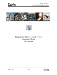
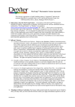
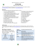
1
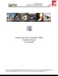
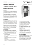
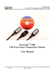
USER MANUAL
XP-0128 TSM USB Stick Demo Board
Temperature Sensor Module (TSM)
USB Stick Demo Board
User Manual
8685 rev nc.doc
Update: 05/2012
1 of 12
USER MANUAL
XP-0128 TSM USB Stick Demo Board
Table of Contents
1
2
3
4
5
6
7
Introduction…………………………………………………………… 3
Host computer requirements………………………………………….. 4
Installing the software ………………………………………………... 4
Where to begin with the XP-0128 EVB……………………………… 5
4.1 Demo board overview………………………………………… 5
Where to begin with the XP-0128 PC software……………………… 6
5.1 Temperature Sensor Module overview………………………... 6
5.2 Running TSM USB STICK software…………………………. 6
5.3 Main window buttons…………………………………………. 7
5.4 Zooming ……………………………….……………………… 9
Disclaimer ……………………………………………………………. 11
Revision Table ………………………………………………………… 12
8685 rev nc.doc
Update: 05/2012
2 of 12
USER MANUAL
XP-0128 TSM USB Stick Demo Board
1.
Introduction
The TSM USB STICK has very few parts to highlight how easy it is to interface the TSM
into your current design. Remember the SMBus only requires two digital I/O pins from
your microprocessor. (No analog signals to worry about!)
The featured component of the USB STICK is Dexter’s Temperature Sensor Module
(TSM), consists of the industry standard Dexter ST-60 with a special embedded signal
conditioning ASIC inside the TO-5 can. Due to the low noise amplifier, 17-bit high
resolution ADC and powerful DSP of the TSM very accurate non-contact temperature
measurements can be achieved. Factory Calibrated object and ambient temperatures is
available in RAM of the TSM. This is accessible by the industry standard two wire serial
SMBus protocol or via 10-bit PWM (Pulse Width Modulated) output of the device.
The SMBus allows for multiple zone temperature control – up to 100 sensors can be read
via four common wires.
Traditional IR Detector voltage output is in the microvolt range requiring specialized
electronics to minimize noise, readout electronics, calibration and compensation for
system integration. Using the integrated ASIC with our detectors inside the TO-5 can:
•
•
•
•
•
•
•
•
Electronics are placed at the detector, greatly reducing electrical noise.
Temperature measurements now in digital format.
System integration time and expertise is reduced
Less OEM time to market
Lower system costs
Smaller footprint
Plug and Play
Calibrated output from factory
System Flexibility
The TSM USB STICK demo board, (p/n: XP-0128) is designed to support the infrared
temperature sensor module (TSM). The main purpose of the TSM USB STICK demo kit
is to allow customers to evaluate the TSM for virtually any application quickly. The
communication between PC and the demo board is accomplished via USB.
The TSM USB STICK demo Kit contains the following items:
1. TSM USB STICK demo board (EVB), pre-programmed with USB a
boot loader and demonstration firmware.
2. DVD-ROM, containing the PC USB HID demo software.
Our TSM USB STICK is based on the Microchip PIC18F14K50 which offers a cost
completive hardware designs, low cost development tools and software which could be
an excellent starting point for any hardware design. Dexter offers design services and
could customize the demo board to meets your needs as well.
Please contact Dexter for further information.
8685 rev nc.doc
Update: 05/2012
3 of 12
USER MANUAL
XP-0128 TSM USB Stick Demo Board
2.
Host computer requirements
For the demo to function correctly the following hardware and software requirements
must be met:
• PC-Windows compatible system
• An available USB port
• DVD-ROM drive (for use with the accompanying DVD)
• Microsoft Windows XP sp 1 or higher. Graphics set to 1024x768 or higher.
Processor: 400 MHz Pentium processor or equivalent (Minimum);
1GHz Pentium processor or equivalent (Recommended)
RAM:96 MB (Minimum); 256 MB or above (Recommended)
Hard Disk: Up to 500 MB of available space may be required if Dot Net not installed
• Microsoft Dot Net 3.5 sp 1 or higher. Install DVD has this included.
• Microsoft Dot Net 3.5 sp 1 Chart Control. Install DVD has this included.
3.
Installing the software
The demo board requires very little effort to install. Most of the work is done by the installation
software. Insert the install DVD into the drive on your computer. If auto run is enabled on your
system the software installation should start automatically. If not simply click on the file
“setup.exe” on the DVD drive to start the process.
You may be asked to accept each of the Microsoft software license if not already installed on you
computer.
After the USB software is installed you can connect the demo board to any USB port on the
computer.
To connect the demo board:
1. Unpack and unwrap the TSM USB STICK.
2. Connect the TSM USB STICK to an open USB port on the host system.
The LED will shine a steady RED when on.
The software will be installed in a separate Dexter Research directory and can be accessed from a
shortcut Start/Programs/Dexter Research Center/TSM USB STICK.
8685 rev nc.doc
Update: 05/2012
4 of 12
USER MANUAL
XP-0128 TSM USB Stick Demo Board
4.
Where to begin with the TSM USB STICK demo.
4.1 Demo board overview.
3.
4.
1.
2.
FIG 4.1 Top View
5.
FIG 4.2 Bottom View
Fig.4.1. shows the top view of the demo board. The highlighted areas are:
8685 rev nc.doc
1.
Temperature Sensor Module with 70° Field of View TO-5 package.
“TSM” (p/n: MD-0003).
Please see accompanying TSM data sheet for other models and features.
2.
Status LED. LED is on solid when connected to the PC and talking to Windows.
During temperature sampling the LED will blink at the sample rate.
3.
Upgrade button. Should a firmware update be required, pressing this button while
plugging in the stick will place it in boot loader mode. Special PC boot loader
software will be released should this ever become necessary.
4.
Crystal for the microcontroller (PIC18F14K50).
5.
Microcontroller (PIC18F14K50).
Update: 05/2012
5 of 12
USER MANUAL
XP-0128 TSM USB Stick Demo Board
5.
Where to begin with the XP-0128 PC software.
5.1 Temperature Sensor Module overview.
The TSM USB STICK software is a Windows-based application designed to be used with the
XP-0128 demo board for evaluating Dexter’s TSM series of infrared non-contact Temperature
sensor modules. Basic ambient and object temperature readings of the TSM can be captured,
logged and displayed on the PC screen, providing an easy way to evaluate the TSM for use in
target applications.
5.2 Running TSM USB STICK software.
Insert the TSM USB STICK into any USB port on the PC. You may elect to use a USB extension
cable (not supplied) to provide greater flexibility on detector direction. The TSM USB STICK red
LED should be “ON”.
Launch the software from shortcut in:
Start/Programs/Dexter Research Center/TSM USB STICK .
The Startup screen will be appearing on desktop:
FIG 5.1
After loading, the software will automatically recognize the TSM type, voltage, SMBus address
and open the main screen. The status LED will be RED indicating power is applied, you should
see “TSM USB Stick attached” in the lower left corner indicating communication is established.
8685 rev nc.doc
Update: 05/2012
6 of 12
USER MANUAL
XP-0128 TSM USB Stick Demo Board
5.3 Main window buttons.
Exit button.
Exits the program.
Help button.
Pulls up this User Manual.
Start / Stop button.
Click the “Start” button to begin taking measurements and update graphs.
Button will turn to “Stop”. Click to end taking measurements.
Note: This button will not appear on the screen if there are no
communications with the TSM USB STICK.
Save Log / Log ON button.
Clicking the “Save Log” button will allow you to log a date and time
stamped readings for both temperatures in °C to an Excel csv file.
Note: You must specify a file of your choice each time you click the
“Save Log”. Data is always appended to this file never erased. Button will
change to a light red with “Log ON” when the data log feature is enabled.
Re-click to disable logging.
Print Graph button.
Clicking this button will call up printer dialog screen to print the current
displayed graph.
Erase Graph button.
Clicking this button will erase all data from the current displayed graph.
Thermometer check box.
Checking this check box will display both object and ambient
Thermometers on the screen.
8685 rev nc.doc
Update: 05/2012
7 of 12
USER MANUAL
XP-0128 TSM USB Stick Demo Board
°C °F button.
Here you can select Celsius or Fahrenheit scale. This will change the graph
and thermometer display scale. Note: the Log file is always in °C.
Caution: when changing this setting any data on the graph will be erased.
Display Length pull down button.
Here you can select how much time the “X” axis on the graph represents.
From 5 seconds to 1 hour. The “X” axis is a first in first out display; data
enters on the right and leaves on the left to maintain the selected temperature
history.
Update Time slider bar.
The slider bar in the middle of the screen “Update Time (msec)” sets the
approximate sample time that readings are taken and displayed.
Max and Min limit text boxes and Current reading digital display.
Both object and ambient graphs have “Y” axis maximum and minimum
setting boxes. This set the resolution of the graphs and thermometer on the
screen only; it has no effect on the TSM. Graphs maximum delta = 1000°.
Spline check box.
Checking this check box will display both object and ambient graphs as a
spline curve on the screen. During real time data collection the graph is show
as a point to point line for faster update speed.
Show labels check box.
Checking this check box will display on both object and ambient graphs data
labels for each point. This feature is only useful when you have a few points
on the graph. Labels will make the graph unreadable and slow with large
samples of data. This feature is most useful under zoom conditions. During
real time data collection this feature is disabled for a faster update speed.
Zoom out button.
Clicking this button will remove all zoom levels from the display.
8685 rev nc.doc
Update: 05/2012
8 of 12
USER MANUAL
XP-0128 TSM USB Stick Demo Board
5.4 Zooming.
One nice feature is the ability to zoom in on a section of either graph. This is very useful when
you have a large time window and you would like to see more detail on a small section of activity.
See Fig. 5.2
Axis zoom out
buttons
Fig. 5.2
Use the mouse to highlight the section of graph you are interested in. Place the mouse at the
starting corner, press and hold the left button dragging the mouse to the ending corner.
Now in this example we had elected to highlight a section on the T object graph, we could have
selected a section on the T ambient graph.
Releasing the mouse button will update both graphs as selected.
Zoom out button
Fig. 5.3
Each graph will now have a set of scroll bars and zoom out buttons. See Fig. 5.3.
Zoom out button for each axis will take you back one zoom level for that axis.
8685 rev nc.doc
Update: 05/2012
9 of 12
USER MANUAL
XP-0128 TSM USB Stick Demo Board
Fig. 5.4
Multiple zoom levels are possible; here we have highlighted another section on the first level to
get even finer detail. Now at this level it may be useful to try the “Show labels” checkbox.
Fig. 5.5
To get back to a “NO” zoom state you could click on
each axis zoom out buttons or just click on the global
zoom out button.
Fig. 5.6
Also note that clicking “Erase Graph” or “Start” will go back to the “NO”
zoom state.
8685 rev nc.doc
Update: 05/2012
10 of 12
USER MANUAL
XP-0128 TSM USB Stick Demo Board
6.
Disclaimer
Devices sold by Dexter are covered by the warranty and patent
indemnification provisions appearing in its Term of Sale. Dexter makes no
warranty, express, statutory, implied, or by description regarding the
information set forth herein or regarding the freedom of the described
devices from patent infringement. Dexter reserves the right to change
specifications and prices at any time and without notice. Therefore, prior
to designing this product into a system, it is necessary to check with
Dexter for current information. This product is intended for use in normal
commercial applications. Applications requiring extended temperature
range, unusual environmental requirements, or high reliability
applications, such as military, medical life-support or life-sustaining
equipment are specifically not recommended without additional
processing by Dexter for each application.
The information furnished by Dexter is believed to be correct and
accurate. However, Dexter shall not be liable to recipient or any third
party for any damages, including but not limited to personal injury,
property damage, loss of profits, loss of use, interrupt of business or
indirect, special incidental or consequential damages, of any kind, in
connection with or arising out of the furnishing, performance or use of the
technical data herein. No obligation or liability to recipient or any third
party shall arise or flow out of Dexter’s rendering of technical or other
services.
© 2012 Dexter Research Center, Inc. All rights reserved.
For the latest version of this Manual and software, go to our website at
www.DexterResearch.com
Or for additional information contact Dexter Direct:
Dexter Research Center, Inc.
7300 Huron River Drive
Dexter, MI. 48130 U.S.A.
Phone: +1 (734) 426-3921
Fax: +1 (734) 426-5090
[email protected]
8685 rev nc.doc
Update: 05/2012
11 of 12
USER MANUAL
XP-0128 TSM USB Stick Demo Board
7. Revision Table
Version
nc
8685 rev nc.doc
Modifications
Update: 05/2012
Comment
Release
Date
May 2012
12 of 12