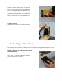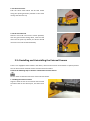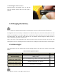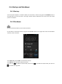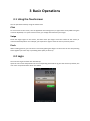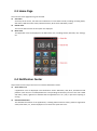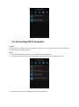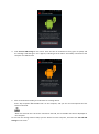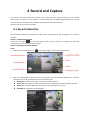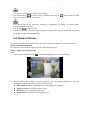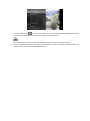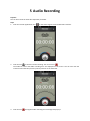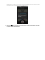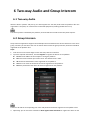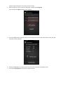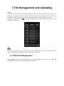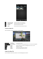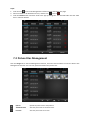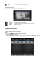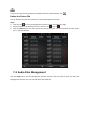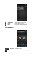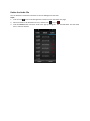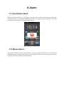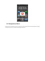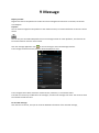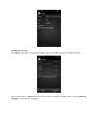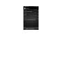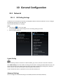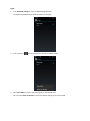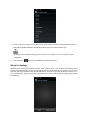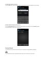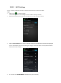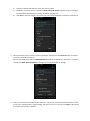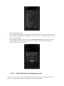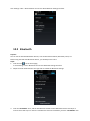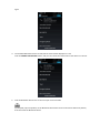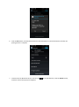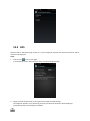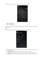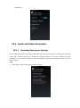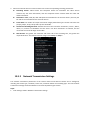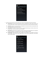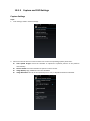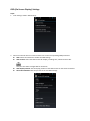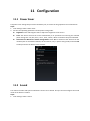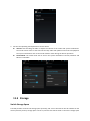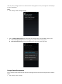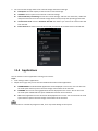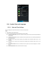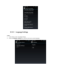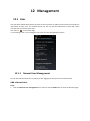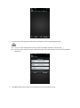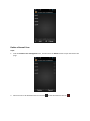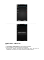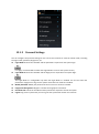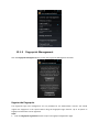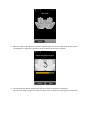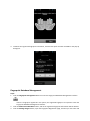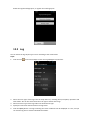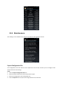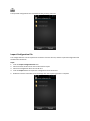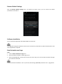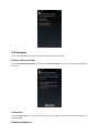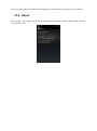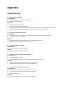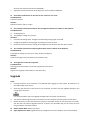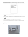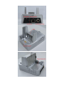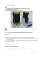
1
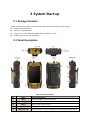
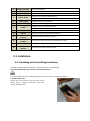
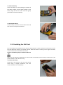
DS-6102HL Portable Video Recorder User Manual (V3.1) UD.6L0204D1029A01 Thank you for purchasing our product. If there is any question or request, please do not hesitate to contact dealer. This manual is applicable to DS-6102HL Portable Video Recorder (V3.1). This manual may contain several technically incorrect places or printing errors, and the content is subject to change without notice. The updates will be added into the new version of this manual. We will readily improve or update the products or procedures described in the manual. Safety Instruction Read, keep and follow these instructions. Make sure that all the related equipment is power-off during the installation. Do not place the product in high-temperature or damp environment, and do not expose it to high electromagnetic radiation. If the product does not function properly, please contact your dealer or the nearest service center. Do not disassemble the product for repair or maintenance by yourself. Only use the battery, power adapter and assembly parts specified by the manufacturer. Consult the authorized dealer or technician from Hikvision for any question and request for product using. Table of Contents Safety Instruction .............................................................................................................................. 2 Table of Contents .............................................................................................................................. 2 1 Introduction .............................................................................................................................. 4 1.1 Overview ........................................................................................................................... 4 1.2 Main Functions ................................................................................................................. 4 1.3 Product Features ............................................................................................................... 5 1.4 Conventions ...................................................................................................................... 5 2 System Start-up ......................................................................................................................... 6 2.1 Package Contents .............................................................................................................. 6 2.2 Panel Description .............................................................................................................. 6 2.3 Installation ........................................................................................................................ 7 2.3.1 Installing and Uninstalling the Battery .................................................................... 7 2.3.2 Installing the SIM Card ............................................................................................ 8 2.3.3 Installing the Micro SD Card .................................................................................... 9 2.3.4 Installing and Uninstalling the External Camera ................................................... 10 2.4 Charging the Battery ....................................................................................................... 11 2.5 Status Light...................................................................................................................... 11 2.6 Startup and Shutdown .................................................................................................... 12 2.6.1 Startup................................................................................................................... 12 2.6.2 Shutdown .............................................................................................................. 12 3 Basic Operations ..................................................................................................................... 13 3.1 Using the Touchscreen .................................................................................................... 13 3.2 Login................................................................................................................................ 13 3.3 Home Page ...................................................................................................................... 14 3.4 Notification Center.......................................................................................................... 14 3.5 Connecting PVR to Computer ......................................................................................... 15 4 Record and Capture................................................................................................................. 17 4.1 Record Video Files ........................................................................................................... 17 4.2 Capture Pictures.............................................................................................................. 18 5 Audio Recording ...................................................................................................................... 20 6 Two-way Audio and Group Intercom ...................................................................................... 22 6.1 Two-way Audio................................................................................................................ 22 6.2 Group Intercom ............................................................................................................... 22 7 File Management and Uploading ............................................................................................ 24 7.1 Video Files Management ................................................................................................ 24 7.2 Picture Files Management .............................................................................................. 26 7.3 Audio Files Management ................................................................................................ 28 8 Alarm ....................................................................................................................................... 31 8.1 Acceleration Alarm.......................................................................................................... 31 8.2 Manual Alarm ................................................................................................................. 31 8.3 Temperature Alarm ......................................................................................................... 32 9 Message .................................................................................................................................. 33 10 General Configuration ............................................................................................................. 36 10.1 Network .......................................................................................................................... 36 10.1.1 3G Dialing Settings .......................................................................................... 36 10.1.2 Wi-Fi Settings .................................................................................................. 40 10.1.3 Wired Network Settings (Reserved) ................................................................ 42 10.2 Bluetooth ........................................................................................................................ 43 10.3 GPS .................................................................................................................................. 46 10.4 Platform .......................................................................................................................... 47 10.5 Audio and Video Parameters .......................................................................................... 48 10.5.1 Recording Parameters Settings........................................................................ 48 10.5.2 Network Transmission Settings ....................................................................... 49 10.5.3 Capture and OSD Settings ............................................................................... 51 11 Configuration .......................................................................................................................... 53 11.1 Power Saver .................................................................................................................... 53 11.2 Sound .............................................................................................................................. 53 11.3 Storage ............................................................................................................................ 54 11.4 Applications .................................................................................................................... 56 11.5 System Time and Language............................................................................................. 57 11.5.1 Date and Time Settings ................................................................................... 57 11.5.2 Language Settings............................................................................................ 58 12 Management ........................................................................................................................... 59 12.1 User ................................................................................................................................. 59 12.1.1 Normal User Management.............................................................................. 59 12.1.2 Personal Settings ............................................................................................. 63 12.1.3 Fingerprint Management ................................................................................ 64 12.2 Log................................................................................................................................... 67 12.3 Maintenance ................................................................................................................... 68 12.4 About .............................................................................................................................. 72 Appendix ......................................................................................................................................... 73 Troubleshooting ...................................................................................................................... 73 Upgrade ................................................................................................................................... 75 Extension Base ........................................................................................................................ 76 Components .................................................................................................................... 76 Function Description ....................................................................................................... 78 Indicators......................................................................................................................... 78 Cautions .......................................................................................................................... 78 1 Introduction 1.1 Overview The portable video recorder (PVR) is operated by wireless control and transmits video and audio stream via 3G mobile networks or Wi-Fi networks. With the built-in GPS module, Bluetooth module, high-definition internal camera, it provides the functionalities of locating the device, capturing the picture, recording the video, etc. The fingerprint identification is also supported by the device and it has various extension ports to meet the actual needs. Thanks to these features, PVR is widely applied to the surveillance projects of crime scene investigations, remote depositions, etc. 1.2 Main Functions Network Settings: Supporting TCP/IP protocols; Transmitting video, audio and alarm data via network Wireless Settings: Built-in 3G and Wi-Fi (2.4G/5.8G) communication module connectable to platform for centralized monitoring Dual-stream Transmission: One for local high-definition storage and one for network transmission Dual SIM Card Design: Single card mode and double card mode are both available. Two 3G SIM cards are supported in double card mode. Two-way Audio: Supporting full duplex two-way audio between device and platform Group Intercom: Supporting half-duplex intercom between devices in the same group Location Service: Built-in GPS module precisely positioning the device and uploading location information to surveillance center Bluetooth: Built-in Bluetooth module supporting two-way audio and file printout using Bluetooth headset or printer Biometric Authentication: Fingerprint identification technology providing high security for access control User Management: User accounts assigned with different permissions in favor of central management and maintenance Built-in 5 megapixels camera taking high definition pictures Supporting external camera to realize simultaneous work of internal & external cameras Supporting one-touch capture Messages can be sent from platform to devices to release notification One-touch manual alarm can be uploaded to the platform Supporting acceleration alarm in special case such as device fall off Temperature alarm avoiding heat damage from the device Built-in LED flash lamp working as the flashlight of internal camera or electric torch Automatically switch to power saving mode to extend the life of battery Supporting date and time settings 1.3 Product Features Easy to carry the mobile terminal, meeting the actual needs of individual work Both internal camera (1080P, 720P, D1, VGA and QVGA) and external camera (D1 and CIF) are supported Adopt H.264 digital coding technology to reduce the storage pressure of the storage medium in the device Built-in 3G and Wi-Fi module transmit audio and video data stably in mobile conditions, using optimization algorithm Built-in GPS positioning module records the locations of the event Central platform software provides functionalities of live view, two-way audio, data storage, device positioning, etc. 16G internal storage space is available and up to 32G external SD card can be installed Different permissions can be assigned to the users The monitoring host provides the LED monitor and buttons, supporting the touch operations Three-proofing technology (water-proofing, dust-proofing, shock resistance) Lithium battery supporting at least 4 hours continuous work SDK of smart operation system can be provided for custom development 1.4 Conventions The DS-6102HL Portable Video Recorder will be briefed as PVR or device. 2 System Start-up 2.1 Package Contents Unpack and check the package contents carefully. The following assembly parts are supplied: Portable Video Recorder (1) Battery (1; 7.4V/2100mAh) Charger (1; AC Input: 100-240V 50/60Hz 0.8A; DC Output: 12V 2A) DVD/CD (with user manual supplied) (1) 2.2 Panel Description Table 2.1 Panel Description No. Name Function Description Show the hidden menu on the screen. 1 Menu 2 Home page 3 Return Return to the previous menu. 4 Record Long press it to enable/disable the recording. 5 Fingerprint area Return to the Home Page. Swipe the finger across the fingerprint area for fingerprint registration. 6 Headset interface Use for the headset. 7 Micro HDMI port HDMI video output connector. 8 PTT 9 Audio+, Audio- 10 Power supply Supply the power for the device. 11 USB interface Universal Serial Bus (USB) port for connecting to the computer. 12 Power 13 Alarm 14 Capture 15 16 External camera interface 3G antenna interface 17 Camera 18 Extension base interface Use for the group intercom. Increase or decrease the audio volume Zoom in or zoom out on the Camera interface Long press it to turn on/off the device Press it to lock/unlock the screen Long press it to send the manual alarm. Capture the picture on the Camera interface; Install the external camera if needed. Install the 3G antenna when the slave SIM card is used. 5 mega-pixel internal camera (with Flashlight built-in) Connect to the device extension base 2.3 Installation 2.3.1 Installing and Uninstalling the Battery The PVR is equipped with one battery to ensure the device normal working. Perform the following steps to install or uninstall the battery: Turn off the power of all the related equipment when you install or uninstall the battery. 1. Remove back cover Loosen the 4 set screws on the rear panel of the device using a straight screwdriver, and then remove the back cover. 2. Install the battery Insert the battery into the opening on the back of the device, making sure the gold contacts on the battery align that on the device. And then gently press down to secure the battery. 3. Uninstall the battery Lift the battery up from the device bottom side and then remove it away from the device. 2.3.2 Installing the SIM Card Two card sockets are provided, one for the main SIM card with a built-in antenna and the other one for the slave SIM card requiring an external antenna. When the device is working in the single card mode, insert the SIM card into the Main Card Socket. Perform the following steps to install the SIM card: When the slave SIM card is adopted, you need to install an external antenna at the top of the device. (The pictures below are for reference only.) 1. Remove the battery Loosen the 4 set screws on the rear panel of the device using a straight screwdriver, and then remove the back cover and battery. 2. Install the SIM card Carefully slide the SIM card into the SIM card socket until the card locks into place. Make sure that the card's gold contacts face into the device and that the upper-left angled corner of the card is positioned correctly. The upper one is Main Card Socket 1 and the lower one is Slave Card Socket 2. 3. Install the antenna Install the 3G antenna at the top of the device if the Slave Card Socket 2 is equipped with the SIM card. 2.3.3 Installing the Micro SD Card The device supports 16G memory itself. And you can also extend its storage capacity using a micro secure digital (SD) card. The SD card socket locates under the rear panel of the device. Perform the following steps to install the micro SD card: 1. Remove the battery Loosen the 4 set screws on the rear panel of the device using a straight screwdriver, and then remove the back cover and battery. 2. Lift the sheet metal Push the sheet metal above the SD card socket along the opening direction (marked on the sheet metal), and then lift it up. 3. Fix the micro SD card Slide the micro SD card into the socket provided, with the gold contacts facing down, until the card locks into the place. By default, the device should mount the micro SD card automatically. 2.3.4 Installing and Uninstalling the External Camera There is a 5 megapixels camera built in the device, which can be used to record videos or capture pictures. You can also install an external camera onto the device if needed. Perform the following steps to install or uninstall the external camera: Do not rotate or bend the connector of the external camera. 1. Installing the external camera Align the white arrow on the external camera with the white label on the device port, and then insert it. 2. Uninstalling the external camera Press the root of the interface, lift it up, and pull out the external camera after the snap joint is opened. 2.4 Charging the Battery Use the authentic original Hikvision battery and charger to ensure the safe operations of the device. Rechargeable Lithium-Ion battery is adopted for the device and you can check the battery level from the battery icon displayed in the upper-right corner of the screen. When the battery level is lower than 15%, the status light at the top of the device will turn to red and flash rapidly. Charge the battery timely to ensure the normal operations of the device. Pull up the cover on the right-side of the device, and then insert the end of charger into the jack. The status light is red in the charging process and it will turn to steady green when the battery is fully charged. 2.5 Status Light The status light at the top indicates the current working status of the device. For details, see the table below: Table 2.2 Status Light Description Status Light Function Description Priority Red and steady Battery is charging. 4 Green and steady Red and fast flashing (200ms open, 100ms close) Green and normal flashing (800ms open, 400ms close) Red and slow flashing (1200ms open, 600ms close) Battery is full. 4 Device is exceptional (e.g., battery level is lower than 15%). 3 Network transmission is in process. 2 The device is in recording. 1 The larger the numeric is, the higher the priority is. 2.6 Startup and Shutdown 2.6.1 Startup Insert the power adapter or install the battery into the device, and then long press the POWER button on the right-side to start up the device. The Login interface will be displayed on the screen after the startup process is complete. 2.6.2 Shutdown Do not uninstall the battery to shut down the device. To shut down or reboot the device, long press the POWER button on the right-side to enter the Shutdown interface, shown as below. Click Power off, and click OK to shut down the device. Click Reboot, and click OK to reboot the device. Click the icon to enable the silent mode; click the icon to enable the ring mode. to enable the vibrate mode; click the icon 3 Basic Operations 3.1 Using the Touchscreen You can operate the PVR by using the touchscreen. Click To act on items on the screen, such as application and settings icons, to type letters and symbols using the onscreen keyboard, or to press onscreen icons, you simply click them with your finger. Swipe Touch the target region on the screen, and then move your finger across the surface of the screen, to reach the desired position. For example, you swipe left or right to view the next or previous picture. Pinch When viewing pictures, you can zoom in and out by placing two fingers on the screen at once and pinching them together (to zoom out) or spreading them apart (to zoom in). 3.2 Login You enter the Login interface after PVR startup. Input the user name and password in the corresponding text fields to log into the device. By default, the user name and password are admin and 12345. 3.3 Home Page You enter the Home page after log into the PVR. Status Bar At the top of the screen, the status bar indicates the current status of PVR, including recording status, GPS status, USB connection status, Bluetooth status, Wi-Fi status and battery status. Date & Time The current date and time of the system are displayed Menu Item The application icons are displayed in the Menu Item area, including Camera, Recorder, File, Settings, etc. 3.4 Notification Center Swipe down from the top of the screen to view the Notification Center. Quick Start Icons 5 application icons are displayed in the Notification Center: Bluetooth, GPS, Wi-Fi, 3G SIM Card and platform. Click the icon to enable/disable the corresponding functionality. The icons are color-coded with blue / white / light-blue to indicate that the applications are on / off / in process of opening or closing. Detailed Information The detailed information of the applications, including USB connection status, platform registration status, GPS status, etc., will be displayed in a list under the quick start icons. 3.5 Connecting PVR to Computer Purpose: Connect PVR to a computer using the USB cable, and then you can copy files from PVR to the computer or copy files from the computer to PVR. Steps: 1. Start the PVR, and then connect it to the computer using a USB cable. 2. Enter the Notification Center, and the message “USB connected” will be displayed on the list. 3. Click the item to enter the USB Mass Storage Settings interface. 4. Click Turn on USB storage on the screen. Then the color of android turns from green to yellow, and the message “USB storage in use” appears, indicating that the PVR is successfully connected to the computer via USB interface. 5. After connected successfully, the PVR works as a storage device. Enter “My ComputerRemovable Disk” on the computer, and you can view and operate the files stored on the PVR. When the external micro SD card is mounted to the PVR, two removable disks will be displayed on the computer. To exit from the storage mode of PVR, eject the device from the computer, and then click Turn off USB storage on the screen. 4 Record and Capture The internal and external cameras can both record video files and capture pictures. For the internal camera, you can switch it to the capture or record mode with the Capture/Record Switch icon; for the external camera, two buttons are provided independently for the functionalities. Take the internal camera as an example: 4.1 Record Video Files Two recording methods are provided for PVR: quick recording mode and recording on the Camera interface. Option 1: Quick Recording Mode Long press the button on the front panel of PVR to start / stop the recording. The recording parameters can be set on the Camera interface. Option 2: Recording on Camera Interface Steps: 1. Click the camera application icon on the Home Page to enter the Camera interface. 2. Slide the Capture/Record Switch icon to the right-side, click the Parameter Settings icon and then configure the recording parameters to meet the actual needs. Resolution: the size of the image, namely, the number of pixels. Frame rate: the frequency of the unique consecutive images (called frames) produced by PVR. Bitrate: the number of bits that are conveyed or processed per unit of time. Flashlight: the dwell time of the flashlight. The external camera does not support the flashlight. 3. Click the Record icon to start recording. The Record icon turns to time in the upper-left corner of the screen. . You can view the record The duration time of the continuous recording is configurable. For details, see Section 10.5.1 Recording Parameters Settings. 4. Click the icon to stop recording. 5. Click the Video/Picture icon in the lower-left corner of the screen to view the record files. For details, see Section 7.1 Video Files Management. 4.2 Capture Pictures Two capture methods are provided for PVR: quick capture mode and capture on the Camera interface. Option 1: Quick Recording Mode Click the Camera button on the right-side panel of PVR capture pictures. Option 2: Capture on Camera Interface Steps: 1. Click the camera application icon on the Home Page to enter the Camera interface. 2. Slide the Capture/Record Switch icon to the left-side, click the Parameter Settings icon and then configure the capture parameters to meet the actual needs. Auto upload: upload the captured picture to the platform automatically. Capture sound: turn on/off the capture sound. Resolution: the size of the captured picture. Image quality: the quality of the captured picture. 3. Click the Capture icon to capture the picture. You can enable/disable the flashlight according to the external circumstances, to increase the clarity of captured picture. You can also capture pictures and set the capture parameters on the recording interface. 4. Click the Video/Picture icon in the lower-left corner of the screen to view the captured pictures. For details, see Section 7.2 Picture Files Management. 5 Audio Recording Purpose: You can also record the audio files separately if needed. Step: 1. Click the recorder application icon on the Home Page to enter the Recorder interface. 2. Click the icon to start the audio recording. The icon turns to . The audio file name and audio recording time are displayed on the screen. You can also view the real-time sound intensity from the pointer position on the index dial. 3. Click the icon during the audio recording and a message box pops up. Click OK, and you can stop the current audio recording; click Cancel, and you can continue the audio recording. The audio recording does not pause during this period. 4. Click the icon in the upper-right corner of the screen to view the recorded audio files. For details, see Section 7.3 Audio Files Management. 6 Two-way Audio and Group Intercom 6.1 Two-way Audio With the built-in speaker and pick-up, the PVR supports the two-way audio with the platform after the registration is complete, no need for other associated equipment (including headset and so on). The two-way audio is initiated by the platform, and the PVR cannot send the two-way audio request. 6.2 Group Intercom Group Intercom application supports the half-duplex intercom between the devices which are in the same group, and thus you can talk to the user of another PVR. To start the group intercom, the device should be registered on the platform first. Steps: 1. Click the icon on the Home Page to enter the Group Intercom interface. 2. Input the required information, and click Register to register the device on the platform. Server: the IP address of the computer running the platform. Port: the communication port of the server. The default value is 7333. ID: the device identification name registered on the platform. User: the user name of the device ID account registered on the platform. Pwd: the password of the device ID account registered on the platform. The device ID and the corresponding user name and password should be registered on the platform first. 3. Optionally, you can check the checkbox of Auto register when next boot to register the device on the platform automatically the next time you start the PVR. 4. Select the group to join in, input the password, and then click Join group. You can also click Logout the log out the platform. 5. Press the PTT button on the PVR. You can start the group intercom with other devices after the PVR ticks twice during vibration. 6. Release the PTT button, and the group intercom service stops after the PVR ticks once. 7. You can click Quit group to exit from the group intercom. 7 File Management and Uploading Purpose: 3 types of files are supported, including video files, picture files and audio files. The files created on the same date are stored in one folder which is named by the date, such as 20131106. The device provides a 16G memory, and you can insert an external SD card to extend the storage capacity of the device. Click the file application icon Management interface. on the Home Page and select the user account to enter the File The admin user account has the permission to view and manage the files of all users; while the normal user account only has the permission to view and manage its own files. 7.1 Video Files Management Click the Video tab on the File Management interface, and then click the folder to enter the Video File Management interface. You can view and delete the video files. Upload (reserved) Upload the video files to the platform. Thumbnail View View the video files in thumbnail view. List View View the video files in list view. Delete Delete selected video files from the device. View the Video File Click the video file, and you can play the selected video file. Pause/Play Pause/Play the video. Speed up/down Increase/Decrease the play speed of video. 1x, 2x and 3x are supported. Details View the details of the video, including file name, time, size, etc. Delete Delete the video file. Return Go back to the video file list interface. Record Go to the record interface of camera. Delete the Video File You can delete the video files in batches on the File Management interface. Steps: 1. Click the icon on the File Management interface to open the Delete File page. 2. Select the folder to be deleted on the list, and the icon turns to . 3. Click the Delete button and then confirm the pop-up dialog box. The selected folder and the video files in it will be deleted. 7.2 Picture Files Management Click the Image tab on the File Management interface, and then click the folder to enter the Picture File Management interface. You can view, upload and delete the picture files. Upload Upload the picture files to the platform. Thumbnail View View the picture files in thumbnail view. List View View the picture files in list view. Delete Delete selected picture files from the device. View the Picture File Click the picture file, and you can view the selected picture file. Upload Upload the picture file to the platform. Details View the details of the picture, including file name, time, size, etc. Delete Delete the picture file. You can swipe left or right to view another picture. Upload Picture to Platform Before you start: The device should be registered on the platform. Steps: 1. Click the icon on the Picture File Management interface, 2. Select the pictures to be uploaded. 3. Click the Upload button, and then confirm the pop-up dialog box. The selected pictures will be uploaded to the platform. The picture that has been uploaded to the platform will be marked with the icon Delete the Picture File You can delete the picture files in batches on the File Management interface. Steps: 4. Click the icon on the File Management interface to open the Delete File page. 5. Select the folder to be deleted on the list, and the icon turns to . 6. Click the Delete button and then confirm the pop-up dialog box. The selected folder and the picture files in it will be deleted. 7.3 Audio Files Management Click the Audio tab on the File Management interface, and then click the folder to enter the Audio File Management interface. You can view and delete the audio files. Thumbnail View View the audio files in thumbnail view. List View View the audio files in list view. Delete Delete selected audio files from the device. View the Audio File Click the audio file, and you can play the selected audio file. Pause/Play Pause/Play the audio. Details View the details of the audio file, including the name, time, size, etc. Delete Delete the audio file. You can click-and-drag the blue slider on the process bar to adjust the audio play process. Delete the Audio File You can delete the audio files in batches on the File Management interface. Steps: 1. Click the icon on the File Management interface to open the Delete File page. 2. Select the folder to be deleted on the list, and the icon turns to . 3. Click the Delete button and then confirm the pop-up dialog box. The selected folder and the audio files in it will be deleted. 8 Alarm 8.1 Acceleration Alarm When the PVR drops down at a fast speed, it will generate acceleration alarm and then upload the acceleration alarm to the platform. Meanwhile, the PVR will vibrate to send a notification, with the message “Acceleration alarm” displayed on the interface. 8.2 Manual Alarm In emergency conditions, press the Alarm button on the side of PVR manually. Then, the manual alarm information will be uploaded to the platform, and the PVR will vibrate to send a notification, with the message “Manual alarm” displayed on the interface. 8.3 Temperature Alarm With the built-in temperature sensor, the PVR will send alarm signal when the body temperature exceeds the upper limit (75°C), to avoid the heat damage to the device. 9 Message Before you start: Register the PVR on the platform to realize the central management of devices. For details, see Section 10.4 Platform. Purpose: You can send message from the platform to the mobile terminal, to release notification to the users of the device. You can only use the iVMS-7200 platform to send message to PVR. For other platforms, this function can be custom-made to meet the actual needs. Click the message application icon on the Home Page to enter the Message interface. The messages received from the platform will be displayed on a list. The message that has been checked is marked as blue; otherwise, it is marked as white. The PVR can receive up to 1000 items of messages, and the new messages will cover the old ones when the number exceeds the limit. To view the message: Click the item on the list, and you can view the detailed information of the selected message, To delete the message: Click Delete under the list, select the messages, and then click OK to delete the selected messages. You can also press the Menu button on the front panel to show the hidden menu, and click Delete all messages to remove all the messages. 10 General Configuration 10.1 Network 10.1.1 3G Dialing Settings 2 SIM cards can be installed on the PVR, including Main SIM Card and Slave SIM Card. You can configure the 3G dialing settings for each SIM card. Take the Main SIM Card as an example: Steps: 1. Click the icon on the home page, or click Settings > NET > Dial settings to enter the Dialing Settings interface. 2. Select the Main SIM Card. Enable Dialing When 3G dialing and Wi-Fi networks are both available, give priority selection to the Wi-Fi networks. Click Enable dialing on the main SIM card settings interface after installing the Main SIM Card. Then, the device will connect to the mobile networks and the information including the dialing status, SIM card status, network standard and IP address will be displayed automatically. 3 types of SIM card status are provided: No card, Normal and Abnormal. Advanced Settings You can configure the advanced settings for 3G VPDN (Virtual Private Dialup Network). Steps: 1. Click Advanced settings to enter the APN Settings interface. The default 3G VPDN account will be displayed on the page. 2. Click the button on the front panel to shown the hidden menu. 3. Select New APN to create a new access point for the 3G SIM card. You can select Reset to default to restore the default settings of the current APN. 4. Input the service provider’s name, access point name (APN), username, password, Mobile Country Code (MCC), Mobile Network Code (MNC) and then select the authentication type. To configure the 3G VPDN settings, please contact the local operator and consult the network parameters. 5. Click the button again, and click Save to save the parameters. White List Settings With the white list settings, the device will get online / offline (log in / out the platform) according to the remote command message. Up to 8 groups mobile number can be added to the white list. You can send text with authorized mobile number to the SIM card No. of device to operate the device remotely. Text “on”, and the device will get online (log in the platform); text “off”, and the device will get offline (log out the platform). To add mobile number to white list: Click the Add button, input the mobile number on the text field, and then click OK to save the settings. To delete mobile number from the white list: Click the Delete white list button, select the mobile number on the white list, and click Delete to delete the selected mobile number from the white list. Standard Format The standard format has been set when the device is delivered, including CDMA and WCDMA. The standard format of the installed SIM card should be the same with that of the device. 10.1.2 Wi-Fi Settings You can connect the device to the Wi-Fi networks and transmit the data via the Wi-Fi. Steps: 1. Click the icon on the home page, or click Settings > NET > Wi-Fi settings to enter the Wi-Fi Settings interface. 2. Swipe the slider of Search network to the right side to enable the Wi-Fi settings. 3. Click the Search network item, and then the Wi-Fi networks available will be searched and displayed on a list automatically. You can view the signal strength, connection status, security mode and other information of the networks. 4. You can also click ADD NETWORK to add the access point manually. 1) 2) 3) Input the network SSID and then select the security mode. Optionally, you can check the checkbox of Show advanced options, and then input to configure the information including proxy settings, IP address, gateway, etc. Click Save to save the settings. The new access point will be displayed on the Wi-Fi networks list. 5. Select the access point on the list, input the password, and then click the Connect button to connect the device to the Wi-Fi networks. You can also check the checkbox of Show password to display the password in plaintext, or check the checkbox of Show advanced options to configure the proxy settings or IP settings. 6. Click the connected access point of Wi-Fi networks, and you can view the detailed information of the access point, including status, signal strength, link speed, and so on. You can click Forget to disconnect the device from the Wi-Fi networks. 7. Wi-Fi Protected Setup (WPS) Wi-Fi Protected Setup (WPS) is a computing standard that attempts to allow easy establishment of a secure wireless network. With the WPS function, the device can be connected to the Wi-Fi networks, with no need of password. Press the WPS push button on the router, and click WPS PUSH BUTTON on the device interface to search the WPS networks. Then, the device will be connected to the available WPS networks automatically without the password. 10.1.3 Wired Network Settings (Reserved) The device can be connected to the wired networks and transmit the data via the network cables. This function is reserved and it requires for the support of device extension base. Click Settings > NET > Wired network to enter the Wired Network Settings interface. 10.2 Bluetooth Purpose: You can use the PVR with Bluetooth devices, such as Bluetooth headsets, Bluetooth printer, etc. Before using the PVR with Bluetooth devices, you should pair them first. Steps: 1. Click the icon on the home page, or click Settings > NET > Bluetooth to enter the Bluetooth Settings interface. 2. Swipe the slider of Bluetooth to the right side to enable the Bluetooth settings. 3. Click the “DS-6102HL” item, and the PVR becomes visible to other Bluetooth devices nearby for 2 minutes and it will stop in 2 minutes. To disable the function immediately, click the “DS-6102HL” item again. 4. The available Bluetooth devices nearby will be searched and displayed on a list. Click the SEARCH FOR DEVICES button, and you can refresh the information of the devices on the list. 5. Click the Bluetooth device item on the list to pair it with the PVR. If prompted, input the passkey on the Bluetooth device side. See the instructions about the passkey that came with the Bluetooth device 6. Click the Pair button, and the Bluetooth device will be displayed on the Paired Devices list after the pairing process is complete. 7. To disconnect the Bluetooth device, click the icon and then confirm the pop-up message box. of the paired device, click the Unpair button, 10.3 GPS With the built-in GPS positioning module, the current longitude, latitude and speed of the device will be detected and displayed. Steps: 1. Click the icon on the home page, or click Settings > NET > GPS settings to enter the GPS Settings interface. 2. Swipe the slider of GPS switch to the right side to enable the GPS settings. The longitude, latitude, time, positioning accuracy and speed of the device will be displayed automatically when the GPS signal is available. Locate the device in open space to receive the GPS signal if no data is displayed. 10.4 Platform The PVR can be connected to iVMS-7200 series platform, providing functions including live view, two-way audio, alarm, etc. Steps: 1. Click Settings > NET > Platform settings to enter the Platform Settings interface. 2. Swipe the slider of Platform to the right side to enable the platform settings, and then input the required information. Platform IP Address: the IP address of the computer running the platform server. Platform Port: the network communication port of the platform. The default value is 7660. Device ID: the identification name of the device. The device ID should be registered on the platform first. 10.5 Audio and Video Parameters 10.5.1 Recording Parameters Settings The recording parameters of the internal and external camera can be configured, including the recording stream type, resolution, frame rate, duration and maximum bitrate. You can also configure the basic parameters on the Camera interface. The new recording settings will be activated the next time the camera started. Steps: 1. Click Settings > MED > Recording parameters settings. 2. Select the internal camera or external camera to set the corresponding recording parameters. Recording Stream: Video stream and composite stream are selectable. The video stream contains only the video information, and the composite stream contains both the video and audio information. Resolution: 1080P, 720P, D1, VGA and QVGA are selectable for the internal camera; and only the D1 and CIF are selectable for the external camera. Frame Rate: the number of unique consecutive images (called frame) per second. Full frame rate (24 fps), 20 fps, 15 fps, 10 fps and 5 fps are selectable. Continuous Recording Duration: indicates the size of the record file. Continuous, 15 min., 30min., 45min, 1h, and 2h are selectable. No time limit is set when Continuous is selected, and the record file size cannot be larger than 1.99G. Max. Bitrate: The greater the resolution and frame rate of the recordings are, the greater the required bitrate is. The maximum bitrate ranges from 64Kbps to 8Mbps. 10.5.2 Network Transmission Settings The network transmission parameters of the internal camera and external camera can be configured, including the stream type, resolution, frame rate, maximum bitrate and encoding type. The new network transmission settings will be activated the next time the platform gets stream. Steps: 1. Click Settings > MED > Network transmission settings. 2. Select the internal camera or external camera to set the corresponding transmission parameters. Stream Type: Video stream and composite stream are selectable. The video stream contains only the video information, and the composite stream contains both the video and audio information. Resolution: 720P, D1, VGA and QVGA are selectable for the internal camera; and only the D1 and CIF are selectable for the external camera. Frame Rate: the number of unique consecutive images (called frame) per second. Full frame rate (24 fps), 20 fps, 15 fps, 10 fps and 5 fps are selectable. Max. Bitrate: The greater the resolution and frame rate of the transmitted video are, the greater the required bitrate is. The maximum bitrate ranges from 64Kbps to 4Mbps. Encoding Type: VBR (Variable Bit Rate) and CBR (Constant Bit Rate) are selectable. The value of selected CBR is the same with that of Max. Bitrate; and the value of VBR adjusts automatically under the Max. Bitrate. 10.5.3 Capture and OSD Settings Capture Settings Steps: 1. Click Settings > MED > Camera settings. 2. Select the internal camera or external camera to set the corresponding capture parameters. Auto Upload Images: Check the checkbox to upload the captured pictures to the platform automatically. Camera Sound: Check the checkbox to open the camera sound. Image Quality: High, Middle and Low are selectable. Image Resolution: the size of the captured picture. VGA, 1.3M, 3M and 5M are selectable. OSD (On Screen Display) Settings Steps: 1. Click Settings > MED > OSD settings. 2. Select the internal camera or external camera to set the corresponding OSD parameters. OSD: Check the checkbox to enable the OSD settings. OSD Content: Select the OSD content for display, including time, GPS and camera No.. Only the time OSD is configurable for the device. OSD Display Position: Set the display position of the OSD content on the Camera interface. Check the OSD Effect: Get the preview of the new OSD settings. 11 Configuration 11.1 Power Saver The power saver settings help to stretch the battery life, to ensure the long operation time of the device. Steps: 1. Click Settings > DEV > Power saver. 2. Set the corresponding parameters for the power saving mode. Brightness: Click-and-drag the slider to adjust the brightness of the screen. Time: The device will lock the screen automatically if no operations occur during the selected power saving time. 15s, 30s, 1min., 2min., 5min., 10min., 30min. and Never sleep are selectable. Disconnect the Network in Power Saving Mode: Select Yes to disconnect the device from the network (such as 3G mobile networks, Wi-Fi networks, etc.) in power saving mode; and select No to always connect the device to the network. 11.2 Sound The volume of media and system notifications can be set as desired. And you can also configure the sound mode of the device if needed. Steps: 1. Click Settings > DEV > Sound. 2. Set the corresponding sound parameters for the device. Volume: Click-and-drag the slider to adjust the volume of the media and system notifications. The media volume refers to the sound of two-way audio with platform and record file playback. The system notifications refer to the sound of button touch during the device operations. Sound Mode: The sound mode can be set for the system notifications. Normal, Vibration and Mute are selectable. 11.3 Storage Switch Storage Space The PVR provides a built-in 16G storage space (internal); and a micro SD card can also be installed on the device (external). Priority storage space can be set, and the files will be saved on the other storage space until the priority storage space is full. When both the storage spaces are full, a message will be displayed to send a notification. Steps: 1. Click Settings > MED > Storage settings. 2. Click the Audio & Video storage item, and select the storage priority for the audio & video stream. Internal Storage Priority: Give the storage priority to the internal storage space. External Storage Priority: Give the storage priority to the external storage space. Storage Space Management You can view the status of the internal and external storage space and format the storage space if needed. Steps: 1. Click Settings > DEV > Storage. 2. You can view the storage status of the internal storage and external storage. Total Space: the total capacity of the internal or external storage. Available: the free space of the internal or external storage. Internal Memory Formatting: Format the internal storage, and then the video files, audio files and picture files stored on the internal storage will be erased, except the operating system data. Unmount SD Card: Click the Unmount SD card item before you remove the external SD card from the PVR. Erase SD Card: Format the external SD card and you will lose all the data stored on the SD card. 11.4 Applications You can view the current applications running on the device. Steps: 1. Click Settings > DEV > Applications. 2. Swipe left or right, and you can view the detailed information of the applications. DOWNLOADED: The downloaded applications will be displayed on the screen. You can also view the used space and free space of internal storage at the bottom of the interface. RUNNING: The current running applications will be displayed on the screen. You can also view the used space of RAM and free space of RAM at the bottom of the interface. ALL: All the applications on the device will be displayed on the screen. You can also view the used space and free space of internal storage at the bottom of the interface. Do not delete or uninstall the programs at will, for it may cause damage to the system. 11.5 System Time and Language 11.5.1 Date and Time Settings You can configure the system data and time to meet the actual needs. Steps: 1. Click Setting > SYS > Date and time. 2. Set the corresponding date and time parameters for the system. Automatic Date & Time: Check the checkbox and the system will use the network-provided time automatically. Automatic Time Zone: Check the checkbox and the system will use the network-provided time zone automatically. Set Date: Set the system date manually (only available when Automatic Date & Time is not enabled). Set Time: Set the system time manually (only available when Automatic Date & Time is not enabled). Use 24-hour Format: Check the checkbox and the system time will be displayed in 24-hour format. Choose Date Format: Select the date format for display. 11.5.2 Language Settings Steps: 1. Click Setting > SYS > Language settings. 2. Click the Language settings item, and then select the system language. 12 Management 12.1 User Only the admin (called administrator) account has the permission to add the new normal user and edit the information of other users. The created normal user can only edit the information of itself, and cannot view the files recorded by other users. Click the icon on the Home page; or click Settings > SYS > User management to enter the User Management interface. 12.1.1 Normal User Management You can add, edit and delete the normal users after logging into the system as the administrator. Add a Normal User Steps: 1. Click the Common user management item, and then click the Add button to open the Add User page. 2. Input the user name, password and confirm password in the corresponding text fields. The user name and password can only contain the English alphabets, numeric and “_”. The user name cannot be longer than 20 characters; and the password cannot be longer than 16 characters. 3. Click OK to confirm the settings. The created users will be displayed on a list. Delete a Normal User Steps: 1. Click the Common user management item, and then click the Delete button to open the Delete User page. 2. Select the user to be deleted on the list. The icon of the selected user turns to . 3. Click the Delete button and confirm the pop-up dialog box. The selected user will be deleted. Assign Permissions for Normal User Steps: 1. Click the Common user management item, and then select the user on the list. 2. Check the checkboxes to assign the permissions for the selected user. 9 permissions are selectable: camera settings, file management, GPS settings, Wi-Fi settings, 3G settings, platform management, time settings, maintenance and storage management. 12.1.2 Personal Settings You can configure the personal settings for the current user account to meet the actual needs, including the login mode, password, fingerprint, etc. Login Mode 1: Check the checkbox and the password is required for the system login. It is highly recommended to enable the Login Mode 1 to ensure the system security. Login Mode 2: Check the checkbox and the fingerprint is required for the system login. The Login Mode 2 is configurable only when the Login Mode 1 is enabled. You can use either the password or fingerprint to log into the system when both the modes are enabled. Modify Password: Modify the password of the current user account if needed. Fingerprint Management: Register or delete the fingerprint information. Password Lock: Check the checkbox and the password is required to unlock the system. Logout: Log out the system and you can log into the system with another user account. 12.1.3 Fingerprint Management Click the Fingerprint management item to enter the Fingerprint Management interface. Register the Fingerprint The fingerprint login and management are only available for the administrator account. You should register the fingerprint in the system before using the fingerprint login function. Up to 10 pieces of fingerprint information can be registered. Steps: 1. Click the Fingerprint registration button to open the Fingerprint Registration page. 2. Select the finger to be registered, and then swipe the finger you select on the sensor at least 3 times. The fingerprint is registered successfully when the yellow process bar is complete. 3. The selected finger will be marked with a blue point after the fingerprint registration. You can select another finger and repeat the above steps to register the new fingerprint information. 4. To delete the registered fingerprint information, click the blue point and then click Yes on the pop-up dialog box. Fingerprint Database Management Steps: 1. Click the Fingerprint management button to enter the Fingerprint Database Management interface. If there is fingerprint registered in the system, the registered fingerprint is required to enter the Fingerprint Database Management interface. 2. Click the Delete Entire Database button, and all the registered fingerprint information will be deleted. 3. Click the Manage Fingers button, open the Fingerprint Registration page, and then you can select and delete the registered fingerprint, or register the new fingerprint. 12.2 Log You can search the logs by the type or time according to the actual needs. Steps: 1. Click the icon on the Home Page to enter the Log Management interface. 2. Select the main type of the logs from the drop-down list, including Alarm, Exception, Operation and Information. You can also select All as the main type to search all the logs. 3. Select the minor type of the logs under the selected main type. 4. Specify the start time and end time for the log search. 5. Click the Query button. The logs matching the search conditions will be displayed on a list, and you can click the log item to view the detailed information. 12.3 Maintenance Click Settings > SYS > Maintenance, and you can maintain and upgrade the device. Export Configuration File The configuration file of the device can be exported to the SD card, and thus you can configure other devices with the same settings. Steps: 1. Click the Export configuration file item. 2. Select the external SD card or internal SD card for export. 3. Select the saving path for the configuration file. 4. Click the Export button to export the configuration file to the SD card. The exported configuration file is formatted as PVR_version_date.CFG. Import Configuration File The configuration file can be imported to the device from the SD card, and the imported configuration file should match the device. Steps: 1. Click the Import configuration file item. 2. Select the external SD card or internal SD card for import. 3. Select the configuration file from the SD card. 4. Click the Import button to import the configuration file to the device. 5. Reboot the device to activate the new settings after the importing process is complete. Restore Default Settings Click the Restore default settings item, and reboot the device. Then, you can restore the default parameters of the device. Software Installation You can install the application files downloaded on the SD card. The application program should be stored on the root directory of the SD card and the authorization code of the application is required. Boot Animation and Logo Step: 1. Click the Boot animation or logo item. 2. Select the boot animation or boot logo for set. 3. Select the package file or picture file from the SD card, and you can set the boot animation and logo for the device as desired. The boot animation should be in the *.zip format; the boot logo (480*800) should be in the *.jpeg format. USB Debugging Only for the R&D (Research & Development) engineer to debug the device. Restore Factory Settings Click the Restore factory settings item, and click the Reset device button to restore the factory settings for the device. Device Test Click the Device test item, and you can detect the running status of the device’s hardware module (not recommended). Running Information Only for the R&D (Research & Development) engineer to locate and solve the system error information. 12.4 About Click Settings > SYS > About, and you can view the system information including device model, serial No. and software version. Appendix Troubleshooting The device cannot start up. Possible Reasons: a) The battery has not been installed on the device. b) The battery is out of power Solutions: 1. Install the battery on the device. 2. Connect the power adapter to the device. 3. After connecting the device to the power adapter, wait for the icon of charging battery which will be displayed on the screen. And then long press the Power button to start up the device. No signal is displayed on the screen. Possible Reasons: a) The camera is set in External Camera mode while the external camera has not been installed. b) The external camera is out of work. Solutions: 1. Switch the camera to Internal Camera mode or install the external camera. 2. Check the external camera and replace it if needed. There is no audio in record files. Possible Reason: The recording stream is set as Video Stream. Solution: Set the recording stream as Composite Stream. Failed to start the two-way audio with platform. Possible Reasons: a) The network signal is unstable. b) The two-way audio function of the device has been enabled by other client. Solutions: 1. Move the device to places where the network signal is available. 2. Try it again after the two-way audio of the device stopped. The voice heard on the device side is small. Possible Reasons: a) The volume of the audio output on the device side is low. b) The volume of the microphone on the platform side is low. c) The headset is broken. Solutions: 1. Adjust the volume of the audio output on the device side. 2. 3. Adjust the volume of the microphone on the platform side. Replace the broken headset. The SD card cannot be detected. Possible Reasons: a) The SD card is damaged. b) The file system in the SD card is damaged. Solutions: 1. Insert the SD card to the card reader and then connect it to the computer. If you cannot open the storage space of SD card, replace the damaged SD card. 2. Back up the data stored on the SD card and then format it. 3G Dialing failure Possible Reasons: a) No 3G SIM card is installed on the device. b) The format of the 3G SIM card does not match that of the device. c) The external antenna has not been installed when the slave SIM card is used. Solutions: 1. Install the 3G SIM card on the device. 2. Select the 3G SIM card which has the same format of the device. 3. Install the external antenna when using the slave SIM card. The network transmission indicator does not light after successful dialing. Possible Reasons: a) The platform settings are incorrect. b) The platform account conflicted. c) It’s in the platform registration process. d) Only one indicator is available for the device and there is a process with higher priority than network transmission running on the device. Solutions: 1. Edit the platform settings to according to the actual needs. 2. Use another platform account to avoid the conflict. 3. The indicator will light after the platform registration process is complete. 4. Check the current indicator status. For details, see Table 2.2 Status Light Description. It’s too slow to transmit images. Possible Reasons: a) The current network signal is bad. b) The bitrate of the network transmission is too large. Solutions: 1. If 3G dialing is adopted, check the current signal strength; if Wi-Fi networks is adopted, check that whether there is another wireless network with the same frequency band, and if yes, use a new wireless network which has the only frequency band. Wireless networks with the same frequency band cause interference to each other, and it will 2. decrease the network transmission bandwidth. Adjust the transmission bitrate according to the actual network bandwidth. The buttons of the device or the icons on the screen are out of use. Possible Reason: The device crashes. Solution: Reboot the device and try it again. The network transmission indicator does not light and the device is offline on the platform. Possible Reasons: a) 3G dialing failure. b) The platform settings are incorrect. Solutions: 1. Check the 3G dialing status. Configure the 3G dialing settings again if needed. 2. Configure the platform settings again according to the actual needs. 3. Restore the device to factory settings and configure the parameters after the device reboot. The network transmission indicator lights and the device is offline on the platform. Possible Reason: The platform settings are incorrect or have not been configured. Solution: Check and configure the parameters on the platform side. The fingerprint cannot be recognized. Possible Reason: The fingerprint information has not been registered on the device. Solution: Register the fingerprint information on the device first. Upgrade Steps: 1. Connect the device to the computer via a USB cable after logging in to the system. And then turn on the USB storage of the device. 2. Select the disk directory of the device on the computer, and then copy the upgrade package to the storage space of device. 3. 4. It is recommended to store the upgrade package under the system root directory. Turn off the USB storage, disconnect the device from the computer and then power off the device. Restart the device, and at the same time long press the Audio+ button on the device for 15 seconds. You will enter the System Upgrade interface. 4 options are selectable and you can select the item using the Audio+ and Audio- button. Reboot System Now: Reboot the device. Apply Update from ADB: Upgrade device by package stored on the computer (not recommended). Install Package from SD Card: Select it when the upgrade package is stored on the internal SD card. Install Package from External SD Card: Select it when the upgrade package is stored on the external SD card 5. 6. Press the PTT button to activate the selected item. Select the upgrade package from the storage space of SD card, using the Audio+/Audio- to move up/down. Press the PTT button to upgrade the device. The upgrading process will be complete after about 15 seconds. 7. 8. 9. Do not power off the device in the upgrading process. Select the reboot system now item and click the PTT button to reboot the device. Input the user name and password to log in to the system, and the new settings will be activated. Extension Base Components Function Description Steps: 1. Lift up the rubber strip on the bottom of PVR to expose the metallic contact. 2. Put the device into the extension base. 3. Fix the device to the extension base with the holder. You can connect the PVR to computer via the USB interface on the extension base for data backup. The PVR can access the internet via the network interface. The RS-232 serial interface provides debugging functionality for the device developer. Indicators The battery charging indicator is off when there is no battery in the battery charging cabin. Plug in the power adapter after the battery is put into the battery charging cabin, and the power supply indicator lights. The battery charging indicator lights in red during the charging process; and it turns to green when the charging is complete. Cautions Avoid heat source and direct sunlight. Charging temperature ranges from 32°F (0°C) to 113°F (45°C), in voltage of 8.4V. Use only the battery and charger specified by the manufacturer. 0301001031203