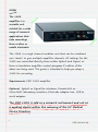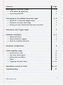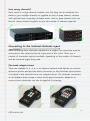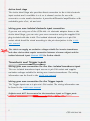
1
1902 application guide
A guide to setting up CED 1902 amplifiers
03/9/2012
Cambridge Electronic Design Ltd.
Notes
The 1902
amplifier is a
versatile unit
suitable for a wide
range of research
applications that
take recordings
from surface or
needle electrodes.
The 1902 is a single channel modular unit that can be combined
into ‘stacks’ to give multiple amplifier channels. All settings for the
1902 are controlled directly from within Spike2 and Signal, or
from a standalone amplifier control program if neither of the
above are being used. This guide is intended to help you setup a
1902 for recording.
Requirements: CED 1902 amplifier
Optional: Spike2 or Signal for Windows, Power1401 or
Micro1401 laboratory interface, Electrode adaptor box, USB to
serial adaptor.
The CED 1902 is sold as a research instrument and not as
a medical device within the meaning of the EC Medical
Device Directive.
1
CED 03/09/12
Contents
Page
What type of 1902 do I need?
3-4
• 1902 options by application
• How many channels?
Connecting to the Isolated electrodes input
• CED1902-11 Electrode adaptor boxes
• CED1902-10 Active Head Stage
• Wiring your own Isolated electrode input connection
Transducer and Trigger inputs
3
4
4-5
4
5
5
5
Software Installation
6-7
• Spike2 and Signal
6
• Signal conditioner support
6
• Check for available COM ports
7
Hardware configuration
8
1902 amplifier setup
9
• Control of the 1902
10
• The 1902 control panel
11
• Setting Gain and Offset
• Filters
12
13
• Triggering the Input clamp
14-15
Standalone control of 1902
16-17
Troubleshooting
17
2
CED 03/09/12
What type of 1902 do I need?
1902 options by application
The following table shows the 1902 options that would typically be required
for a range of research applications. This table is intended for use as a guide
only. If you have other requirements or wish to check the suitability of the
1902 for your specific application, you should contact CED directly.
Application
Transducer
(non-invasive)*
Non-Isolated
Isolated
Standard gain
Optional gain
x100,000)
x1,000,000)
(x100 –
(x1000 –
Optional Input
clamp#
Optional
ECG front
end##
*
Transducer
(invasive)**
MEP recording
(TMS)#
EMG
ECG##
EEG
Evoked
potentials
* Including Force, acceleration, temperature, strain and displacement transducers. Standard gain is x1 – x100,000
**Includes Blood pressure or other invasive transducers that are connected to a subject
#Input clamp is required if recording fast responses or from close to the site of stimulation
##ECG front end with 5 lead switching under software control
The isolated input port of the 1902 will give the best results for
most recordings due to its superior gain and low-noise.
3
CED 03/09/12
How many channels?
Each 1902 is a single channel modular unit, but they can be combined into
stacks to give multiple channels or supplied as dual or quad channel variants
with optional rack-mounting. Multiple stacks, dual or quad channel units can
then be ‘daisy-chained’ together to give the number of channels required.
Connecting to the Isolated electrode input
When recording from electrodes attached to a subject, the electrodes must be
connected to the isolated electrode input port of the 1902. There are a
number of connection options available, depending on the number of channels
and the electrode types being used.
Electrode adaptor boxes
These are available in 2, 4, 8 or 16 channel variants with bipolar or common
reference options and provide direct connection to the Electrode input sockets
of multiple 1902 channels from one compact device. The electrode connectors
on the adaptor boxes accept 1.5mm touch-proof electrodes. Adaptors to
connect 2mm electrodes can also be supplied if necessary.
4
CED 03/09/12
Active head stage
The Active Head Stage also provides direct connection to the 1902 electrode
input sockets and is available in a 2 or 4 channel version for use with
concentric or wire needle electrodes. It provides differential amplification with
switchable gains of x1, x3 and x10.
Wiring your own Isolated electrode input connection
If you are not using one of the CED1902-11 electrode adaptor boxes or the
Active Head Stage, you can wire your own connectors using the supplied DIN
plug included with the 1902. The Isolated electrode input is a 6-pin DIN
socket which should be wired according to the pin descriptions in the 1902
user manual.
The 1902 can supply an excitation voltage suitable for invasive transducers
and other devices that require connection between a human subject and the
Isolated electrode input. Contact CED for further details.
Transducer and Trigger inputs
Wiring your own connection for the Non-isolated transducer input
The non-isolated transducer input uses an 8-pin DIN socket and supplies
excitation voltages suitable for driving non-invasive transducers. The wiring
information can be found in the 1902 user manual.
Wiring your own connection for the Trigger inputs
The Trigger inputs use a 4-pin mini-DIN socket. The wiring information can
be found in the 1902 user manual.
Subjects must NOT be connected to the transducer input or Trigger ports.
5
CED 03/09/12
Software installation
Spike2 and Signal
Install the software from the supplied CD. After setting the installation
directory, your name and organisation and selecting Compact, Custom or
Typical setup, the following page will appear.
Signal conditioner support
This option is used to install software
support for a signal conditioner along
with Spike2 or Signal. Select CED
1902 signal conditioner and click Next.
Information on setting up a 1902
amplifier for recording can be found in
the 1902 amplifier setup section.
The CED 1902 amplifier is
controlled via a COM port
(RS232). Many desktop PC's will
have at least one COM port
available (usually COM1). For
laptops and PCs without an
available COM port, a USB to serial
adaptor can be used instead. This
should be plugged in to an available
USB port before continuing.
6
CED 03/09/12
If you know the COM port you want to use, select it here and click Next. If
you are not yet sure which port you want to use you can check for available
COM ports as described below, or select COM1 at this stage and then simply
change the 1902 COM port in the Edit menu Preferences > Conditioner
section in Spike2 or Signal later on.
Check for available COM ports
All available COM ports are listed in the
Windows Device Manager. The quickest way to
open the Device Manager on any version of
Windows is to use the Windows key + R
keyboard shortcut to open the Run command,
enter devmgmt.msc in the dialog and Click OK.
You can also open the Run command from the
Start menu in Windows XP. In Windows 7 you
can access the Device Manager from the
Control Panel in the Start menu or open the
Run command from the All Programs >
Accessories folder in the Start menu.
In the list of hardware devices should be an entry for Ports (COM & LPT).
Click on this to show the available ports. You can edit the COM number
assigned to a port for most devices by double-clicking on the entry. Click on
the Port Settings tab and then the Advanced... button. You can set the COM
port number from a drop-down list.
Once the 1902 conditoner support option has been selected you can continue
with the installation. There are a number of other options, some specific to
Spike2 or Signal, that you can select as required.
7
CED 03/09/12
Hardware configuration
The diagram below shows the control line from the computer as either a
direct serial port connection OR via a USB to serial converter. This connection
is made to the back of the 1902 amplifier unit or to the bottom-most 1902
in a stack of multiple amplifiers.
For recording from surface electrodes on humans the isolated ‘Electrode’ input
of the 1902 must be used. Output of the amplified/filtered signal is then
produced at the ‘Amp Out’ BNC connector.
8
CED 03/09/12
1902 amplifier setup
With mains power off, connect the power cable and included RS232 serial
cable to the rear of the 1902. Connect the power cable to a power outlet and
the RS232 cable to an available COM port on the host PC or to the USBserial adaptor that you connected to a USB port on the host computer during
software installation. Switch on the mains outlet to power up the 1902. Once
the green Power LED is lit, the 1902 is ready for use.
If you are using Spike2 or Signal and the 1902 conditioner support option
was selected during the installation, complete control over the 1902 amplifier
settings is provided via a control panel which can be used to adjust amplifier
gain and offset, modify filter settings and enable triggering and clamp
duration if the 1902 has been fitted with the input clamp option. If powered
up and connected to the PC, the 1902 will be detected when Spike and
Signal are first run.
By default, the control software expects each 1902 channel to be connected
to the corresponding ADC port number on the 1401 interface using BNC
cables, which you should connect now. This example uses a single 1902,
channel 0, which is connected to ADC 0.
Don’t want to use the ADC port on the 1401 that matches the 1902 channel
number by default? For instance you may already be using ADC Inputs 0-2
but want to connect a 1902, which is set to channel 0, to ADC Input 3. To
do this you need to change the 1902 channel number to match the ADC
Input using the rotary switch on the rear panel of each 1902 channel.
9
CED 03/09/12
Control of the 1902
Spike2
The 1902 control panel is accessed from the Conditioner… button in the
Channel parameters dialog. Double click on a channel in the Channels tab of
the Spike2 sampling configuration to open the Channel parameters. If a 1902
is connected to the 1401 port that is selected in the Channel parameters
dialog, the Conditioner… button will be enabled. Click on this to open the
1902 controls. During sampling you can access the 1902 control panel from
the Sample menu Conditioner option
Signal
The control panel for the 1902 is available from the Port setup tab of the
sampling configuration in Signal. If you select an ADC port in the list, and
there is a corresponding 1902 attached, the CED 1902 button is enabled.
Click on this to open the 1902 controls. During sampling you can access the
1902 control panel from the Sample menu Conditioner option.
If Spike2 or Signal fail to detect the 1902, check that the COM port settings
in the software match the COM port that the 1902 is connected to. You set
the COM port to use from the Edit Preferences menu Conditioner tab. To
check which COM port the 1902 is connected to, see Check for available COM
ports above.
10
CED 03/09/12
The 1902 control panel
To the right of the main control panel is an oscilloscope window which shows
incoming data for the currently selected 1902. The control panel can also be
accessed during sampling by selecting Signal conditioner... from the Sample
menu.
The oscilloscope window in the control panel is only shown if a 1401 is
connected to the PC and switched on.
The Port list shows the current 1902 channel and the Input drop down list
sets the input mode for the selected 1902. With an input clamp the list will
display EEG unclamped and will also contain a list of times in milliseconds.
These specify the length of time to apply the input clamp in response to a
pulse input on the Trigger 2 port of the 1902. If the clamp option is not
fitted you should set the input to use Isolated EEG for recording from
electrodes.
The EEG unclamped, clamp duration settings and Isolated EEG options all use
the isolated stage of the amplifier and are the only inputs suitable for
recording responses from surface electrodes.
11
CED 03/09/12
Setting the Gain and Offset
The Gain and Offset controls scale the incoming data. The Reset calibration
button can be used to automatically adjust the scale and offset values in the
sampling configuration so that the incoming data is displayed in units of Volts,
millivolts or microvolts, depending on the gain you have selected in the 1902
control panel. Whenever the gain or offset is changed in the control panel,
Spike2 and Signal will adjust the gain and offset settings in the sampling
configuration to keep the y-axis display showing the same units in the data
file but, for this to update automatically, you first need to set how the
incoming data should be scaled into the y-axis units.
Using the Reset calibration option
If you have set the units to Volts, millivolts or microvolts in the sampling
configuration, you can use the Reset calibration button. Adjust the gain and
offset controls so that the largest waveform feature you want to record fits in
the oscilloscope display window without clipping, and then click the Reset
Calibration button. During recording any changes to the gain will be
automatically applied to the y-axis display in the data file.
Want to use different y-axis units?
If you want to use different units of measurement you first need to set these
in the sampling configuration. For example, you may be recording from a
force transducer that has an output of 0.1525 Newtons per mV and want to
apply this scale to the data file. In this case you need to express the
transducer output in terms of Units per Volt (152.5), which can then be set
in the Input in Volts x field in the Channel parameters dialog in Spike2. If you
are using Signal, you need to multiply this value by the full scale input (5 or
10V) and enter it in the Data value at full scale input field in the Port setup
Parameters dialog in Signal. Once the correct units have been set you can
then adjust the gain settings in the 1902 control panel to setup recording.
Any changes made to the gain settings from this point will automatically
update the y-axis display in the data file.
12
CED 03/09/12
Filters
The Filters section of the control panel is used to apply filtering to the
incoming data.
High and Low pass filters
You can specify the type of filter to use and the frequency cut-off values from
the drop-down menus for both high and low pass filters. You can also type
your own values into the Cutoff fields if the value you want to apply is not
displayed in the drop-down list.
Notch filter
The notch filter is set to remove a single frequency and is usually set to the
local mains power supply (50 or 60Hz, depending on location).
The Notch filter is only provided for diagnostic purposes and should not be
used during experiments.
AC couple
This option blocks the DC component of a waveform and can be thought of as
a high-pass filter with a cutoff of 0.16Hz. This can be useful if your feature of
interest is small compared to the large DC level. Unlike the High and Low pass
filter settings, which are applied at the amplifier output, the AC couple is
applied at the input.
13
CED 03/09/12
Triggering the input clamp
Stimulus artefacts can often saturate the input of an amplifier, causing a
period of ‘lost’ recording while the amplifier input returns to a normal level.
This can cause problems if the response is very fast or is being recorded from
close to the site of stimulation. The diagram above shows a fast MEP response
from the electrode (Fig. A) that is missed due to the amplifier saturation
caused by the stimulus artefact (Fig. B).
14
CED 03/09/12
The CED 1902 amplifier can have a stimulus clamp option fitted that
suppresses the artefact by clamping the amplifier input to ground during
stimulation. This prevents saturation of the amplifier input, allowing fast
responses to be recorded (Fig. C).
The input clamp should be triggered marginally before the stimulator to
ensure that the clamp circuit is fully engaged before the stimulus is applied, as
in the above diagram. Depending on the stimulator specifications, one way to
achieve this is to use a single pulse output of 0.5 to 1ms duration and route
this to both the trigger input of the stimulator and the Trigger 2 input using
a T-piece. The same pulse can then trigger the 1902 clamp with the rising
edge of the pulse and the stimulator with the falling edge, ensuring the
necessary delay. Alternatively you can set up a second pulse on another digital
output to trigger the 1902 clamp circuit separately from the stimulator.
When using the input clamp, the active head stage should not be used. You
should also turn off the AC couple option and set the 1902 high-pass filter
setting to None.
15
CED 03/09/12
Standalone control with Try1902 and Ctl1902
Don’t have Spike2 or Signal? In this case you can use the diagnostic program
(Try1902) and standalone amplifier control program (Ctl1902) supplied on
the installation CD shipped with the 1902. These applications provide the
necessary setup and control applications for standalone 1902 use and are
installed in a folder called CED 1902 Support, available from the Windows
Start menu
Open the Try1902 program to set the required COM port and
communications for the 1902. To check which COM port the 1902 is
connected to, see Check for available COM ports above.
Select the COM port and a corresponding 1902 Channel from the drop down
lists in the main toolbar of Try1902. A message at the bottom of the toolbar
gives information about the detected 1902. If you are using multiple 1902’s
you can check each channel for communication using the drop-down list.
Once communication with the 1902 has been established, select Set port and
channels… from the File menu in Try1902. This allows you to set global
settings for COM port and the first and last 1902 channels for use by the
Ctl1902 application.
16
CED 03/09/12
By default the Try 1902 application will try and communicate with channel
0 as the first available channel on the 1902. If the first channel on your
1902 is not 0, you need to set the First 1902 channel to use option to match
your first 1902 channel number. Try1902 will then search up to the channel
number specified in the Last… field. If you are using multiple 1902 units
where the channel numbers have a gap (for example, dual and quad-channel
units numbered 2-3 and 8-11 respectively) you should set the Last field to
match the highest channel number you want to use.
Click OK to confirm these settings and then exit the Try1902 program,
before opening Ctl1902 from the CED 1902 Support folder. This opens a
control panel similar to that supplied in Spike2 and Signal but without the
oscilloscope display of incoming data. See The 1902 control panel section for
details on how to set inputs, gain and filter settings.
Troubleshooting
A diagnostic program, Try1902, is included on the 1902 installation CD and
can be used to provide details of any problems. Double-check that the 1902 is
connected to the PC via a COM port or USB-serial interface and open the
Try1902 program, which can be found in the 1902 folder and accessed from
the Start menu. The main toolbar displays the current communication status
of any detected 1902’s and also contains drop-down lists for COM ports and
1902 channels, from which you can select a 1902 channel to check. If a
1902 channel has been detected there are also
options to perform Communications, Trigger and
EEPROM tests and to Calibrate. There is also an
Interactive mode with which individual software
commands can be sent to the 1902 for diagnostic
purposes. If you are still having problems establishing
communications with the 1902, you should contact
CED directly for help either by phone or email at
[email protected].
17
CED 03/09/12