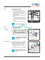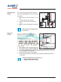
1
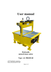
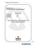
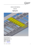
Panel saw Model DS
User manual
/i
Machine
Model DS - Type 123
Order (machine) number
123456
Customer
AaBbCcDdEeFf
Date
03-2010
Version
Final (Version 1.0)
© Machinefabriek Elcon B.V.
No part of this publication may be reproduced, transmitted, transcribed, stored in any retrieval system or
translated into any human or computer language by any means or in any form, without the prior written
permission of Elcon.
Elcon reserves the right to make changes without notice to both this manual and to its products described
within this manual. Nothing in this manual represents any contractual or other commitment on the part of
Elcon and should not be taken as such. All possible care has been taken in the preparation of this
publication. However, if you find errors or would like to make suggestions for improvement then write to
Elcon.
This manual was originally written in English. If applicable, a copy is available on written request.
/i
Machinefabriek Elcon B.V.
P.O. 72
2450 AB Leimuiden
The Netherlands
Visiting address: Waaier 2, 2451 VV Leimuiden
Tel.: +31 (0) 172 508891; Fax: +31 (0) 172 507892
e-mail: [email protected]
Table of contents
1
2
3
Safety
1.1
General................................................................................................................................... 7
1.2
Warning signs......................................................................................................................... 7
Classification ..................................................................................................................... 7
Signs on the machine ........................................................................................................ 8
1.3
EC declaration of conformity (Certification) ............................................................................ 8
1.4
Intended use........................................................................................................................... 8
1.5
Safety devices ........................................................................................................................ 9
Emergency stop................................................................................................................. 9
Protective cover................................................................................................................. 9
Signs on the machine ........................................................................................................ 9
Cutting restrictions............................................................................................................. 9
Exhaust ............................................................................................................................. 9
Thermal cut-off .................................................................................................................. 9
1.6
Disposal.................................................................................................................................. 9
Description
2.1
Overview............................................................................................................................... 11
2.2
Characteristics...................................................................................................................... 11
Cutting restraints ............................................................................................................. 11
2.3
Specifications ....................................................................................................................... 12
Standard machine ........................................................................................................... 12
Exhaust (requirements) ................................................................................................... 12
Ambient conditions .......................................................................................................... 12
Type plate........................................................................................................................ 12
2.4
Control unit ........................................................................................................................... 13
Operation
3.1
Overview............................................................................................................................... 15
3.2
Preliminary............................................................................................................................ 15
Personal safety................................................................................................................ 15
Start-up............................................................................................................................ 15
Direction change over...................................................................................................... 16
3.3
Vertical cutting ...................................................................................................................... 16
Example 1 ....................................................................................................................... 16
Example 2 ....................................................................................................................... 16
Stop with fine tuning ........................................................................................................ 17
3.4
Horizontal cutting.................................................................................................................. 18
3.5
Additional utilities.................................................................................................................. 18
Panel lifters...................................................................................................................... 18
Mid fence system............................................................................................................. 18
Horizontal strip cutting ..................................................................................................... 19
Double cut scoring........................................................................................................... 19
Programming rail for repetitive dimensions ..................................................................... 20
4
5
6
Maintenance
4.1
Preventive actions ................................................................................................................ 21
4.2
Corrective actions ................................................................................................................. 21
Troubleshooting
5.1
Diagnostics ........................................................................................................................... 23
5.2
Observed irregulations.......................................................................................................... 23
Machine related ............................................................................................................... 23
Reset the thermal protection ........................................................................................... 24
Product related ................................................................................................................ 24
Additional deliveries
About this manual
The vertical panel saw model DS, hereafter referred to as ‘the machine’ is an Elcon
product. This user manual provides information about day-to-day use, cleaning,
maintenance and repair. If applicable, the appendix includes information about the
options that go with the standard machine.
-
Familiarize yourself with the content;
Follow the instructions;
Never change the order of he operations to be carried out.
Other accompanying documentation:
/i
Quick start guide
Information and procedures to get going quickly
Installation manual
Information about assembling and connecting the machine
Commissioning form
A tick-off list, used for end delivery
1
Safety
1.1
General
WARNING
-
1.2
Operation, maintenance and repair activities are reserved to qualified
persons only.
Do not modify the machine.
Do not remove any safety devices.
Obey the local statutory regulations.
Warning signs
Safety signs are attached to the machine to give safety information. All safety signs
are repeated and usually further explained in this manual.
Classification
Safety signs are of the three internationally accepted types and described below.
/i
Warning sign that identifies a hazard.
In this example: Cutting danger.
Mandatory action sign that communicates an action to be taken to avoid a hazard.
In this example: Put on protective gloves.
Prohibition symbol that defines a prohibited action.
In this example: Do not use a forklift.
User manual Model DS - Version 1.0
7
Signs on the
machine
/i
High voltage
Do not use a forklift truck.
Hand injury (in the two cutting
directions)
Read me.
Lift position
1.3
EC declaration of conformity (Certification)
The machine is CE certified. It means that the machine complies with the essential
requirements concerning safety and hygiene. The directives that have been taken
into consideration in the design are listed in an enclosed document.
1.4
Intended use
The machine is designed and manufactured to cut panel material horizontally (from
the left to the right) or vertically (from top to bottom). All other or additional use will
be considered to be not in conformity with the purpose.
/i
Item
Specification
Material
Sheet work such as wood fibre and block board, plywood, synthetic material, formica and the like*. This specification excludes processing solid
wood.
*
8
If any doubt, contact your supplier.
User manual Model DS - Version 1.0
1.5
Safety devices
Emergency stop
The machine is provided with one emergency
stop button (A) on the control unit. Hit the
button in case of an emergency. The power
supply will be interrupted immediately.
The machine has no main switch.
Use this button as such, if necessary.
A
Protective cover
In case of opening the cover of the saw housing, the electrical power supply will be
interrupted immediately.
Signs on the
machine
The signs on the machine are part of the safety provisions. They must not be
covered over or removed, and must be legible during the entire life of the machine.
- Check this regularly;
- Replace or repair signs that have become illegible or damaged.
Cutting
restrictions
Horizontal cutting
Red spots on the rulers indicate a not allowed linear measure. Use the panel lifters
to by-pass this problem. Refer to chapter 3: Operation.
Vertical cutting
If the saw-beam is not fixed in a pre-defined position, the motor will not start.
Exhaust
The machine is equipped with a provision to connect an exhaust system. When
installed properly, this system starts-up at one go with the machine.
Thermal cut-off
The machine is protected against overheating. I.e.: if the power consumption
exceeds the factory setting, the motor stops running.
1.6
Disposal
The use and maintenance of the machine includes no environmental dangers. Most
parts can be disposed in the regular way. The lead parts inside this machine require
special disposal.
/i
ENVIRONMENT
Make sure to comply with local legislation, regulations, instructions and
precautions concerning health, safety and environment.
Dismantle the machine as follows:
- Have an expert supervise the dismantling process;
- Dismantle the machine in easy to handle parts;
- Dispose the dismantled parts according the regulations.
User manual Model DS - Version 1.0
9
10
User manual Model DS - Version 1.0
2
Description
2.1
Overview
F
G
A
B
H
E
I
D
A
B
C
D
E
F
G
H
I
2.2
Cutting restraints
C
Control unit
Emergency stop
Lower beam
Saw-beam
Saw-unit (with saw blade housing)
Fixed meter point(s)
Stop for vertical cutting
Entry (exit) roller
Mid fence system
Characteristics
/i
Cutting length [mm]
Panel length [mm]
- maximum
- minimum
Panel dimensions (lxw) [mm]
- minimum
User manual Model DS - Version 1.0
3.300
4.300
with mid fence
3.300
200
4.300
200
3.000
200
600 x 200
600 x 200
600 x 200
11
2.3
Standard
machine
Exhaust
(requirements)
Ambient
conditions
Type plate
Specifications
/i
Type 155
Type 185
Type 215
Dimensions (lxdxh)
4510 x 1450 x 2265
mm
4510 x 1450 x 2565
mm
5510 x 1140 x 2865
mm
Weight
700 kg
745 kg
865 kg
Noise emission
< 75,6 dB(A)
< 75,6 dB(A)
< 75,6 dB(A)
Cutting length
3300 mm
3300 mm
4300 mm
Cutting height
1550 mm
1850 mm
2100 mm horizontal /
2150 mm vertical
Cutting depth
55 mm
55 mm
55 mm
Saw blade diameters
250 mm; bore 30 mm (carrier pawls 7 mm; pitch 42 mm)
Speed
5100 rpm
Feed through
Hand operated
Power (S6)
3 kW
Pressure P
6 < P < 10 bar
Item
Specification
Connection
100 mm
Minimum air speed
20 m/s
Under-pressure
3500 Pa at 20 m/s
Item
Condition
Temperature T
5 < T < 40
Relative humidity
< 90%
/i
/i
The (standard) Elcon type plate is attached to the saw-unit and contains information
about the items below.
/i
Type
NR.
A.D.
∅
VOLT.
12
Model
Machine serial number
Year (of production)
Saw blade diameter [mm]
Voltage [V]
AMP
FREQ.
P
N
Current [A]
Frequency [Hz]
Power consumption [kW]
Speed [rpm]
(CE logo)
User manual Model DS - Version 1.0
2.4
Control unit
A, B and C are standard positions. The positions D until G are reserved for options,
identifiable by a term or an icon. Position H is the fixed place for the option Digital
read-out.
A
B
C
D
E
F
G
H
Emergency stop button
Stop
Start
H
G
F
Digital read-out
E
D
C
B
A
User manual Model DS - Version 1.0
13
14
User manual Model DS - Version 1.0
3
Operation
WARNING
-
3.1
Operation work is reserved to qualified persons only.
Keep clean the immediate vicinity of the machine to prevent dust
explosion. Clear up the daily waste and dust.
Also refer to chapter 1: Safety.
Overview
A
B
C
G
E
F
D
A
B
C
D
E
F
G
3.2
Personal safety
Control unit
Emergency stop
Stop for horizontal cutting
Saw-beam
Saw-unit (with saw blade housing)
Mid fence system (with pull in/out mechanism)
Stop for vertical cutting
Preliminary
Put on appropriate protective clothes.
/i
Start-up
1.
2.
Connect the plug to an electrical outlet, if not already done.
Release the emergency stop button by turning. Now the machine is in working
order.
User manual Model DS - Version 1.0
15
Direction change
over
The change over from vertical to horizontal
cutting and vice versa is in fact the same
procedure. In one single flowing movement:
- Pull the saw-unit forward (a little
counterclockwise) in a free position by
forcing some resistance, turn over the unit
and push it (clockwise) back.
3.3
Vertical cutting
Vertical cutting starts from fixed marked positions (meter points) on the machine.
The examples below clarify this mode of operation.
Example 1
Example 2
16
Cut off a part with a width of 850 mm
1. Put the panel via the entry roller on the
lower beam.
2. Move the saw-beam to ‘0’ (metres) and
lock this position (A).
3. Move the stop (B) to 850 mm and put the
panel against it.
4. Move the saw-unit above the panel.
5. Push Start to switch on the machine.
6. Put the saw blade into the panel, pull it
steadily downwards and take it out
beneath.
7. Push Stop to switch off the machine.
Cut off a part with a width of 2450 mm
1. Put the panel via the entry roller on the
lower beam.
2. Move the saw-beam to ‘2’ (metres) and
lock this position (A).
3. Move the stop (B) to 450 mm and put the
panel against it.
4. Continue with step 4 until 7 from example
1.
A
B
A
B
User manual Model DS - Version 1.0
Stop with fine
tuning
The stop gives the possibility to fine tune the
set value to a certain extent.
1. Fold up the flip (D), against the ruler.
2. Move the stop to a chosen value and lock
this position with the lever (A).
3. Fine tune this value with the roller (C) and
lock the new, precise value with the lever
(B).
4. Fold down the flip again.
94
96
95
97
98
1 10
2
3
4
6
8
10
4
5
6
7
8
1
12
0
9
11
11
7
10
10
10
5
10
10
10
10
0
99
A
3
11
11
11
11
11
B
C
12
D
To use the maximum margin: turn
the roller to a position in the middle.
User manual Model DS - Version 1.0
17
3.4
Horizontal cutting
Cut off a part with a height of 850 mm
1. Put the panel via the entry roller on the
lower beam, against the stop (A).
2. Move the saw-unit to 850 mm and lock
this position (B).
3. Move the saw-beam to the left of the
panel.
4. Push Start to switch on the machine.
5. Put the saw blade into the panel, pull it
steadily to the right and take it out at the
end.
6. Push Stop to switch off the machine.
A
B
Put wedges in the saw-cut. It prevents the upper part from bending.
3.5
Additional utilities
Panel lifters
Red spots on the rulers indicate a not allowed
linear measure. Use the panel lifters to by-pass
this problem.
- Fold up the panel lifters (A) one by one.
- Take into account that the distance
changes for 20 mm (see the sticker on the
saw-unit).
A
An alternative (optional) method to
by-pass the problem is to move the
back frame.
Mid fence system
The mid fence (with end stop) is in fact the
lower beam at a higher level with the same
functionality. The system is made up of
modules that are built-in every metre.
- Use the knob (A) to pull out a mid fence
module.
- Touch the key (B) to let the module go in.
The use of the mid fence makes
handling small panels more comfortable.
18
B
A
User manual Model DS - Version 1.0
Horizontal strip
cutting
The repeat-stop allows repetitive horizontal
strip cutting, adjustable from 40 up to 500 mm.
26
C B A
25
20
Adjustment
1. Set the stop to a chosen value (A), i.e. 50
mm.
2. Lock the stop with the knob (B).
3. Lower the runner (C) to the top of the
panel.
4. Lock the saw-unit hand tight with the knob
(D).
13
12
11
10
9
D
8
7
6
5
4
E
50
49
48
47
46
45
44
43
42
4
Put the stop in the storage bar (E) if
it is not used.
Double cut
scoring
Scoring is a preliminary treatment that
provides chip-free cutting. The depth of the
notch made by scoring is adjustable.
B
Adjustment (on a waste panel)
1. Turn the Allen screw (A) to set the depth.
2. Make sure that the result is satisfactory.
3. Repeat the setting, if necessary. This
adjustment comes about by trial and error.
A
Vertical cutting
1. Move the saw-unit underneath the panel.
2. Push the device (B) up (is: score position).
3. Put the saw blade into the panel, pull it steadily upwards and take it out at the
top. The result is a chip-free notch.
4. Push the device down (is: cut position).
5. Put the saw blade into the panel again, pull it steadily downwards and take it
out beneath.
Horizontal cutting works out in the same way:
- Scoring: from the right to the left.
- Cutting: from the left to the right.
User manual Model DS - Version 1.0
19
Programming rail
for repetitive
dimensions
20
For horizontal cutting, the programming rail
provides the possibility to lock extra stops for
repetitive dimensions.
1. Move the saw unit to the chosen value
and lock this position.
2. Push in the catch (A).
3. Loosen the nearest displaceble stop (B)
inside the rail, move this stop against the
pin (catch, A) and fasten it again. Use an
Allen key.
B
A
User manual Model DS - Version 1.0
4
Maintenance
WARNING
-
4.1
Maintenance work is reserved to qualified persons only.
Also refer to chapter 1: Safety.
Preventive actions
/i
Machine part
Check
Action
Frequency
Guides
For dirt
Clean. Do not use
compressed air.
Daily
Brass scrapers
For a build-up of dirt
Clean.
Every 50 hours
Horizontal saw-unit
guide on both sides
Clean. Use light oil
and finish with a dry
cloth.
Every 50 hours
Upper and lower vertical saw-beam
guides
Clean. Use light oil
and finish with a dry
cloth.
Every 50/100 hours
Dust scrapers on the
top rail
Soak in light oil.
Every 100 hours
CAUTION
-
4.2
Do not apply oil or grease to the chains.
Anyhow: do not apply oil to a machine part unless this is specified explicitly.
Corrective actions
/i
Machine part
Check
Action
Frequency
Saw blade
Sharpness
Replace*.
If required
Motor
Running-out time
Contact your supplier if this time goes
beyond 8 seconds.
Regularly
*
Explained in this section.
User manual Model DS - Version 1.0
21
1.
2.
3.
4.
Turn the screws (A) a quarter to open the
saw house. Use a screwdriver or a coin.
Hold the flange (B) with the supplied tool
(C).
Loosen the socket head screw (D).
Replace the saw blade. The mortise joint
assures a correct placement.
Only install saw blades that correspond with the specifications of
Elcon. Refer to section 2.3: Specifications.
22
C
D
B
A
User manual Model DS - Version 1.0
5
Troubleshooting
WARNING
-
5.1
Repair work is reserved to qualified persons only.
Also refer to chapter 1: Safety.
Diagnostics
LED indicators in the back side of the control unit show the status of the electronic
functions. From top to bottom:
/i
5.2
Machine related
Colour
Description
1
Green
On: the saw-beam is locked vertically
2
Green
Not used
3
Green
H/V switch. On: vertical cutting position. Off: horizontal cutting position
4
Red
On: the emergency stop circuit is active
5
Green
On: during normal operation. Off: Stop is pushed
6
Green
Off: during normal operation. On: Start is pushed
7
Green
Reserved for the option ‘Automatic shifting back frame’
8
Green
Not used
9
Yellow
Indication power supply (24 V DC)
Observed irregulations
/i
Problem
Possible cause
Solution
The indicator on the
control unit is off.
The emergency stop button is
activated.
Release the E-stop and push
Reset.
No voltage
Check (replace) the fuses.
The saw housing is not closed
(properly).
Close.
The thermal protection is out.
Reset. Explained in this section.
Fuse 1 (...) has gone.
Replace.
The saw-beam is not blocked.
Block.
Pushing Start is ineffective (vertical cutting).
The saw-beam is not blocked.
Block.
The saw-unit is set to cut horizontally.
Turn over the saw-unit.
Pushing Start is ineffective (horizontal cutting).
The saw-unit is set to cut vertically.
Turn over the saw-unit.
User manual Model DS - Version 1.0
23
Reset the thermal
protection
A thermal cut-off is generally the outcome of a
motor overload. It is therefore evident to allow
the motor to cool down. To reset:
1. Switch off the power supply.
2. Remove the cover from the electrical
cabinet (at the rear side of the machine).
3. Push back the black button (B). The red
one (A) comes out. The machine is reset.
A B
Ask assistance If this method does not work
out.
Product related
/i
Problem
Possible cause
Solution
The saw cut is not satisfactory.
Saw blade sharpness is not opti- Replace. Refer to chapter 4:
mal.
Maintenance.
Saw blade securing
Tighten the saw blade again.
Cutting depth is inadequate.
Replace, if necessary.
Saw blade squareness
Dirty guides
The saw cut is not
square.
Clean.
Lower bar guides
Frame is out of position.
Re-adjust. Refer to the Installation manual.
Saw-unit squareness
The dimensions differ.
24
Dirty guides
Clean.
Stops not used
Use the stops.
Wrong adjustments
Cutting horizontally: adjust the
read-out pegs.
Cutting vertically: adjust the
scale.
User manual Model DS - Version 1.0
6
Additional deliveries
User manual Model DS - Version 1.0
25