1
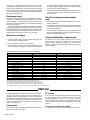
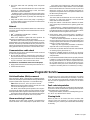
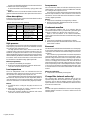
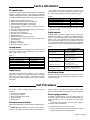
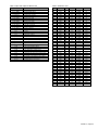
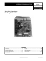
Installation & Maintenance Data IM 660-1 Group: WSHP Part Number: 106018961 Date: May 1999 MicroTech® Water Source Heat Pump Unit Controller Contents Introduction ..................................................................... 2 General Description ......................................................... 3 Component Data ............................................................. 3 Standard Control Features ............................................ 3-4 Factory Configured Options .......................................... 4-5 Commissioning ................................................................ 5 Pre-Start ....................................................................... 5-6 Start-Up ........................................................................ 6-7 Diagnostics and Service ............................................... 7-8 Service Information .......................................................... 9 Test Procedures ......................................................... 9-11 ©1999 AAF-McQuay Incorporated IM 660-1 (Rev. 5/99) Introduction This manual, in conjunction with the Operation & Maintenance Manual, provides information about the new MicroTech Water Source Heat Pump (WSHP) controller and control system used in the AAF-McQuay Incorporated WSHP product lines. The manual describes the controller’s components, input/output configurations, and service procedures. For network installation or commissioning instructions refer to the Operation & Maintenance manual for the MicroTech gateway panel. For general information on a particular WSHP unit, refer to the model-specific Installation Manual (see Table 1). Table 1. Model-specific water source heat pump installation literature WSHP UNIT MODEL CCH/HWH (007-120) CCH/HWH (006-060)* FCV/VWH (007-060) LHP/VWH (07-27) WMH/CWH (007-019) CCW (019-060) INSTALLATION & MAINTENANCE DATA BULLETIN NUMBER lM 526 lM 544 lM 407 lM 439 lM 494 lM 656 *50 Hz only. WARNING Electric shock hazard. Can cause personal injury or equipment damage. This equipment must be properly grounded. Connections and service to the new MicroTech WSHP controller control panel must be performed only by personnel that are knowledgeable in the operation of the equipment being controlled. WARNING Excessive moisture in the control panel can cause hazardous working conditions and improper equipment operation. When servicing this equipment during rainy weather or high humidity conditions, the electrical components in the main control panel must be protected. CAUTION Extreme temperature hazard. Can cause damage to system components. The controller is designed to operate in ambient temperatures from 32°F to 140°F (O°C to 60°C), and in relative humidity up to 95% (noncondensing). The controller can be stored in ambient temperatures from -40°F to 176°F (-40°C to 80°C), and in relative humidity up to 95% (noncondensing). WARNING If the water source heat pump is to be used for temporary heating or cooling, the unit must first be properly commissioned. Failure to comply with this requirement will void the warranty. CAUTION Static sensitive components. Astatic discharge while handling electronic circuit boards can cause damage to the components. Discharge any static electrical charge by touching the bare metal inside the main control panel before performing any service work. Never unplug cables, circuit board terminal blocks, relay modules, or power plugs while power is applied to the panel. NOTICE: This equipment generates, uses and can radiate radio frequency energy and, if not installed and used in accordance with this instruction manual, may cause interference to radio communications. It has been tested and found to comply with the limits for a Class B digital device, pursuant to part 15 of the FCC rules. Operation is subject to the following two conditions: 1. This device may not cause harmful interference. 2. This device must accept any interference received, including interference that may cause undesired operation. These limits are designed to provide reasonable protection against harmful interference when the equipment is operated in a commercial environment. Operation of this equipment in a residential area is likely to cause harmful interference in which case the user will be required to correct the interference at his own expense. McQuay International disclaims any liability resulting from any interference or for the correction thereof. Page 2 / IM 66-1 General Description The new MicroTech WSHP controller is a control system designed to provide control of McQuay and AAF water source heat pumps. The controller enables the mode of operation, monitors the water and air temperatures, and indicates fault conditions. Each new MicroTech WSHP controller is factory wired and factory programmed. The controller is capable of complete, stand-alone unit control if desired, or can be incorporated into a MicroTech network using a MicroTech gateway panel. This new controller utilizes LonWorks technology – the technology geared toward total interoperability of products among different manufacturers. This innovative technology allows the utilization of a central LonWorks-based building control system capable of communicating with all internal building systems. The controller’s intelligence, code written in the Neuron C programming language, is contained within an on-board Neuron chip. Component Data Microprocessor The new MicroTechWSHP unit controller is a preprogrammed microprocessor containing the software required to monitor and control the unit. The controller supports a minimum of 6 analog inputs, 4 digital inputs and 5 digital outputs (including the LED). All electrical connections to the board are provided by three mass termination style headers. Two of the headers are designated strictly for factory wiring; the other for a field wiring harness which terminates to a screw type terminal strip on the unit’s exterior. The controller uses field-adjustable setpoints and fixed, preprogrammed parameters to maintain unit control (many of the preprogrammed parameters can be adjusted with a PC equipped with Monitor software on network units). Status LED An amber, on-board status LED aids in diagnostics by indicating the water source heat pump operating mode and alarm conditions. If there are no current alarrn conditions, the LED will indicate the unit operating mode as shown in Table 2. For more information on alarms, refer to the “Alarm Monitoring & Control” section on page 7 of this manual. A remote status LED is provided with all optional wall mounted temperature sensor packages. It has the same function as the on-board status LED. If used, the remote LED is connected to the new MicroTech WSHP controller at connection #1 on Terminal Board #1. Table 2. Status LED indication STATUS LED STATE On Continually On 0.5 sec, Off 5.5 sec On 5.5 sec, Off 0.5 sec On 0.1 sec, Off 0.1 sec MODE Occupied, Occupied Load Shed Unoccupied Tenant Override, Override Load Shed Alarm Condition (Condensate Overflow, Brownout, Compressor Fault) If the unit controller has not been assigned a logical address, the intensity of the LED is low. If a logical address has been assigned, the LED intensity is high. Temperature sensing The MicroTech WSHP unit controller uses negative temperature coefficient (NTC) thermistors for temperature sensing. A thermistor chart, which provides voltage-to-temperature and resistance-to-temperature conversion data, is included in the “Service Information” section of this manual (Table 9, page 11). The discharge air temperature sensor is located at the inlet to the fan. The leaving water temperature sensor is located in the leaving water line. Standard Control Features The following are standard MicroTech WSHP control features as applicable to the various water source heat pump model types: ● ● ● ● ● ● ● Control heating and cooling from a room sensor. Monitor all safety controls. Provide fan and compressor operation. Monitor discharge air temperature. Monitor leaving water temperature. Provide status of all vital unit functions. Provide optional control outputs. Control heating and cooling from a room sensor All water source heat pumps are designed to control the room (or zone) temperature in response to space temperature detected by the room temperature sensor. Compressor short-cycle protection All water source heat pumps include compressor short-cycle protection. When a compressor is energized, it will remain energized for at least 2 minutes before the temperature control sequence will be allowed to de-energize it. An alarm condition can override this “minimum-on” timer and stop the compressor if necessary. When a compressor is de-energized, it will remain de-energized for at least 5 minutes before the temperature control sequence will be allowed to energize it again. Random start A random start feature is provided with all water source heat pumps. This feature will prevent simultaneous compressor start-up that could otherwise occur after the following events: IM 660-1 / Page 3 • Unit power-up • Unoccupied to occupied changeover • Brownout condition indicate it, and de-energize the compressor. Upon rectification of the brownout condition (when supply voltage remains above 90% of nameplate), normal unit operation will resume. The compressor start delay can be from 180 to 243 seconds (assuming a default initial delay of 180 seconds) and is determined by the unique 48 bit unit ID. High pressure refrigerant alarm Delayed reversing valve de-energization All water source heat pump units have a 10 second reversing valve de-energization delay feature to prevent “swishing.” This delay prevents the reversing valve from returning to its normal (cooling) position for a period of approximately 10 seconds after the compressor is re-energized when the unit is in the heating mode. If necessary, an alarm condition can override the delay timer and de-energize the reversing valve with the compressor. Condensate overflow alarm Should a condensate overflow alarm be detected, the unit controllerwill immediately disable the compressor. Once the overflow alarm disappears, the unit controller will automatically reset the WSHP unit. The condensate overflow sensor is an exposed ring terminal located in the condensate drain pan. The condensate overflow alarm will occur only when the unit is in cooling mode. Brownout alarm The on-board brownout feature is meant to protect the compressor contactors from low voltage or “brownout” conditions. If the supply voltage to the water source heat pumps is below 82% of the nameplate value, the WSHP controller will detect it, If excessive pressure in the refrigeration circuit is detected by the high pressure switch, the compressor and reversing valve will be de-energized immediately. Should the high pressure alarm disappear, the unit controller must be manually reset by disconnecting and reconnecting power to the unit. Low temperature refrigerant alarm Upon detection of a low temperature refrigerant alarm, the unit controller will immediately put the reversing valve in the cooling position for sixty (60) seconds. After sixty (60) seconds, the compressor will be disabled. Should the low temperature alarm disappear, the unit controller must be manually reset by disconnecting and reconnecting power to the unit. The low temperature alarm will occur only when the unit is in heating mode. Low pressure refrigerant alarm Upon detection of a low pressure refrigerant alarm, the unit controller will immediately disable the compressor. Should the low pressure alarm disappear, the unit controller must be manually reset by disconnecting and reconnecting power to the unit. Change filter (network units only) When the water source heat pump fan run-time exceeds a network-adjustable setpoint, a change filter notification is indicated locally and over the MicroTech network. Factory Configured Options In addition to the various heating and cooling options, the water source heat pump product line provides several factory-configured options that affect installation requirements and unit control. These options can be factory programmed and factory wired. Factory installation and wiring can accommodate only one option at a time. The model number code string specifles which options are present in a particular water source heat pump. Field installation will allow all four options simultaneously utilizing an auxiliary module. The following options are described in this section: • Boilerless System Relay • Motorized Valve Relay • Fresh Air Damper Relay • Timed Output Relay Boilerless system relay Relay receives loop water temperature input from MicroTech Loop Water Controller through the gateway panel and provides relay output to electric heat on a call for heat after loop temperature falls. Motorized valve relay Relay provides relay output to motorized valve to shut off water through the unit when compressor is not operating. Fresh air damper relay Provides relay output to open damper whenever the fan is operating in the occupied cycle. Page 4 / IM 66-1 Timed output relay Provides relay output auxiliary load to control its operation based on a specific time schedule different f rom that of the heat pump unit. MicroTech network A varlety of MicroTech unit and auxiliary controllers can be interconnected to form a MicroTech network. A MicroTech network provides a building operator with the capability to perform advanced equipment control and monitoring from a PC equipped with Monitor™ software at a central or remote location. All control sequencing, stop/start and safety monitoring is displayed on the PC screen with the following unique values and parameters for each unit: ● Return air and discharge air temperatures ● Compressor, fan and reversing valve status ● High pressure, low temperature, brownout and drain pan status ● Occupied and unoccupied heat and cool setpoints. Auto/ manual and occupied/unoccupied fan control ● Mode, fault, system, schedule and setpoint operation ● Compressor starts and fan run hours ● Load shed level and tenant override In addition, the following unique operation and maintenance parameters can be displayed for each unit: ● Leaving water temperature ● Return air temperature setpoint adjustment ● ● ● ● ● Adaptive optimal start Occupied/unoccupied (on/cycle) fan mode Room temperature warning Filter changes from fan hours Compressor management: On/off differential, minimum off time, maximum cycle Communication Fallure: If the MicroTech network communication link fails for any reason, the affected WSHP controller will remain operational. Its operating mode will be that last received over the network, or if power is cycled, it will default to occupied. Its minimum position, heating, and cooling setpoints will be those last received over the network, regardless of whether power is cycled. Wall mounted sensor There are four optional wall sensor packages avallable. All wall sensors include a remote status LED and tenant override button. Setpoint adjustment and thermometer are optional wall sensor features that are available in addition to the basic sensor. The wall mounted sensor must be field installed and field wired to the water source heat pump. Terminal Board #1 provides the connections for all room temperature sensor field wiring. Refer to the unit wiring diagram provided and to Bulletin No. IM 529, MicroTech Room Temperature Sensors, for information on wall sensor package installation. Remote room setpoint adjustment The remote setpoint adjustment potentiometer allows the room setpoint to be adjusted up or down by as much as 3°F (1.7°C). It is available with several of the optional wall sensor packages. Tenant override A wall mounted tenant override switch is available for use with all MicroTech WSHP unit controllers. A single press of the tenant override button lasting 1.0 to 6.0 seconds provides a momentary contact closure that causes the unit to enter the “tenant override” operating mode for a set time period (default = 60 minutes). Except for the fact that it is temporary, tenant override operating mode is identical to the occupied operating mode. Pressing and holding the tenant override button for at least 6.0 seconds but not more than 10.0 seconds will activate the network “query address” mode, indicating the unit address in question at the MicroTech gateway panel. Pressing and holding the tenant override button for greater than 10.0 seconds will activate the network “self-configure” mode, requesting the assignment of the next sequential address from the MicroTech gateway panel. Commissioning WARNING Electrical Shock Hazard. Could cause severe injury or death. Fallure to bond the frame of this equipment to the building electrical ground by use of the grounding terminal provided or other acceptable means may result in electrical shock. Service must be performed only by qualified personnel. The following commissioning prodcedures pertain to water source heat pumps equipped with the MicroTech Water Source Heat Pump Controller. These procedures must be performed in addition to the mechanical and electrical system commissioning proceedures that are outlined in the modelspecific installation literature (listing provided in Table 1). Caution: Before power is applied to any unit, the pre-start procedures in the model-specific installation literature must be closely followed. A large part of the commissioned procedure is ensuring that the water source heat pump operates according to its programmed sequence of operation. The water source heat pump sequences of operation are described in the Operation and Maintenance Manual for the MicroTech Water Source Heat Pump Unit Controller. Pre-Start Required tools and literature The following tools and additional literature may be required to properly commission a MicroTech Water Source Heat Pump Controller. Tools: ● Digital voltmeter ● Digital ohmmeter ● Digital thermometer ● General technician’s tools ● PC equipped with Monitor™ software (NetworkWaterSource Heat Pumps only) Literature: ● Model-specific water source heat pump installation bulletin (see Table 1) ● Program-specific sequence of operation bulletin ● MicroTech Monitor Program User’s Manual (if PC is used) Water source heat pump identification Although the water source heat pumps look similar, there are significant intemal differences which are defined by the model number code string. In addition to the basic heating and cooling equipment, the model number code string specifies which factory-configured options have been provided. These options determine the internal wiring configuration and the field wiring requirements. IM 660-1 / Page 5 Obviously, it is extremely important that the correct water source heat pump be placed in the correct location in accordance with job requirements. Proper water source heat pump location should have been determined during the installation process. Nevertheless, proper location must be verified during the commissioning process. Field wiring check The water source heat pump factory-configured options determine the low voltage field wiring requirements. If a specific option is present on a particular water source heat pump (as denoted by the model number), the associated field wiring (if any) must be checked. A unit wiring diagram is provided with each unit shipped, along with a model specific Installation and Maintenance Guide. Referring to this literature and using the following check lists, the start-up technician should thoroughly check the electrical installation before the commissioning process proceeds. Wall sensor packages accordance with the field wiring diagram, on which terminals are clearly labeled. Terminal 4 is used for both the room sensor common and the shield wire. 4. Check that the cable length between the wall sensor package and its water source heat pump controller does not exceed 260 feet. MicroTech network communications units 1. Check that the cable is a twisted, unshielded pair of copper strand conductors. 2. Check that the conductors have been terminated at the units to terminals 5 and 6 of Terminal Board #1 in accordance with the field wiring diagram. 3. Check that the conductors have been terminated at the MicroTech gateway panel in accordance with the field wiring diagram supplied with the panel. Setpoint initialization - network units 1. Check that the cable is twisted, shielded with drain wire (Belden 8729 or equivalent, 22GA). 2. Check that four (4) conductors are available. 3. Check that the conductors have been terminated at the unit and the wall sensor package to screw terminal board #1 in The Water Source Heat Pump setpoint values are held in memory and can only be modified over the MicroTech network. Initially, before any changes are made over the network, the WSHP will use the default factory-set setpoints shown in Table 3. Table 3. Network WSHP default setpoints and adjustability DESCRIPTION Occupied Heating Setpoint Occupied Cooling Setpoint Fan – Occupied Unoccupied Heating Setpoint Unoccupied Cooling Setpoint Fan – Unoccupied Tenant Override – 1st press Tenant Override – 2nd press Differential Auto / Manual Next Filter Change (hours) Clock Schedule Load Shed Start Level Tenant Setpoint Adjustment Low Temperature Waming High Temperature Warning FACTORY PROGRAMMED SETPOINT 70°F(21°C) 74°F (23°C) On 60°F (16°C) 85°F(29°C) Cycle 1:00 Off 2°F (1.2°C) Auto 600 1 Off Off (0°F, 0°C) 55°F (13°C) 95°F (35°C) ADJUSTABILITY RANGE 35°-120°F (1.7°-49°C) 35°-120°F (1.7°-49-C) On, Cycle, Heat, Cycle/Cool On 35°-120°F (1.7°-49°C) 35°-120°F (1.7°-49°C) On, Cycle Off, 0:30 - 8:00 Off, 0:30 - 8:00 1°-10°F (0.6°-5.6°C) Manual (occupied, unoccupied, fan only, off) 100-5000 up to 32 Off, 1 to 7 Off, On (3°F, 1.7°C) 35°F (1.7°C) - high not used low not used - 120°F (49°C) Unoccupied heating setpoint cannot exceed high warning setpoint. Occupied heating setpoint cannot exceed unoccupied heating setpoint. Unoccupied cooling setpoint cannot be lower than low warning setpoint. Occupied cooling setpoint cannot be lower than unoccupied cooling setpoint. Occupied heating and occupied cooling setpoints must differ by at least the differential. Start-Up Following are WSHP start-up procedures for each communication type. The start-up procedure must be performed by a qualified technician for every WSHP on a job. Connections for network wiring are made at terminals 5 and 6 of Terminal Board #1. The FTT-10 (free topology transceiver) on the MicroTech WSHP Controller is polarity insensitive; thus polarity issues need not be addressed. Stand-alone Because stand-alone controllers are independent of each other, they may be started in any order. Page 6 / IM 66-1 PC access A PC cannot be used for stand-alone WSHP start-up; however, the start-up process will be easier and faster if a PC and MicroTech Network are used. If a PC is used, it must be equipped with Monitor™ software. For further information, refer to “PC Connection” in the “Service Information” section of this manual. Procedures for each stand-alone WSHP: 1. Apply power to the unit. Turn the main power switch to “On.” 2. Check the status LED and operating mode changeover devices. The status LED should illuminate 30 to 40 seconds after power-up. If a wall sensor package is used, the remote status LED should also illuminate. Referring to Table 2, verify that the tenant override option is working properly. Do this by pressing the tenant override switch on the wall sensor (if present) and observing the status LED. 3. Verify that the water source heat pump is operating in accordance with its sequence of operation as outlined in the appropriate documentation. Network Prior to the start-up of any Network Water Source Heat Pump Controllers, the following MicroTech network devices must be commissioned: • IBM ® compatible PC with Monitor™ software • MicroTech gateway panel Each water source heat pump on a MicroTech gateway panel trunk must have a unique address. Press and hold the tenant override switch for at least 10 seconds or press and release the service pin at each individual heat pump to request the assignment of the next sequential address from the MicroTech gateway panel. 3. Check the status LED. The status LED should illuminate 30 to 40 seconds after power-up. If a wall sensor package is used, the remote status LED should also illuminate. 4. Verify that network communications between the water source heat pump and the MicroTech gateway panel have initiated. At the network PC, change the operating mode to unoccupied and check that the status LED responds accordingly. For further information on verifying communications, refer to the MicroTech Monitor Program User’s Manual. Refer to the literature supplied with these products for information on installing and commissioning them. After these devices have been properly commissioned, the network water source heat pumps may be started in any order. However, if the start-up order follows the daisy chain from one water source heat pump to the next, it wili be easier to detect any wiring problems that may exist in the communications trunk. 5. Verify that the water source heat pump is operating in accordance with its sequence of operation as outlined in the appropriate documentation. Since the sensed temperatures are fixed at any given moment, adjust the water source heat pump heating and cooling setpoints (at the network PC) to obtain the expected heating or cooling control actions. Adjust any other applicable parameters to obtain the expected water source heat pump control actions. Communications cable check 6. Check that any desired network-executed control features are working properly (load shed, etc.). Perform this check for every communications trunk connected to a MicroTech gateway panel. 1. Be sure that the network communication connectors are disconnected at every water source heat pump on thetrunk. 7. Review the submittal drawings and make any necessary changes to the default water source heat pump setpoints and parameters. 2. Using an ohmmeter, check that there are no shorts between any two connectors in the communications trunk. Procedures for each network water source heat pump: 1. Apply power to the unit. Turn the main power switch to “On.” 2. Set the network address. 8. Check that the fan interlock feature works properly. If the unit is heating or cooling, the fan will be on. If the compressor is running, the fan will be on. In the unoccupied mode, if the fan occupied setpoint is on, the fan will always be on. If the setpoint is heat cycle/cool on, the fan will cycle with the compressor in heating and be on continuously in cooling. Diagnostic Service Unit identification (Wink) command Upon receiving a “Wink” command from a network management node, the heat pump will exhibit the following identification sequence (LED and fan sequences occur simultaneously): LED: Flashes (on 0.5 sec, off 0.5 sec) for 15 seconds. Fan: The heat pump fan will turn off for 5 seconds, turn on for 5 seconds, then off again for 5 seconds. The “Wink” action will disrupt unit operation. The compressor will shut off during this period and the minimum off timer must expire before the compressor will be allowed to run again. This function allows verification of an individual unit network address without a need to open the unit access panels. Alarm monitoring & control The Water Source Heat Pump Controller is programmed to monitor the water source heat pump for specific alarm condi- tions that may occur on the various model types. If an alarm condition exists and is detected by the controller, a “fault” will occur. The water source heat pump controller will indicate the fault and execute appropriate control actions for the alarm conditions. Fault code interpretation Water source heat pump faults are indicated at the status LED (on-board or remote). If a fault exists, operating mode indication will be replaced by a fault indication. During a fault condition, the LED is constantly flashing (on 0.1 sec, off 0.1 sec) until the fault is cleared. Clearing faults Before any fault can be cleared, the alarm conditions that caused it must have returned to normal. When the alarm conditions are gone, a fault may be cleared either automatically or manually. IM 660-1 / Page 7 An auto reset fault will immediately clear whenever the alarm conditions that caused it disappear. A manual reset fault can be cleared by cycling power to the controller. Note: The cause of a manual reset fault should be investigated and eliminated before the unit is placed back into service. Alarm descriptions Following are descriptions of the various faults listed in Table 4 and the low temperature fault. Table 4. Alarm and fault code summary ALARM DESCRIPTION (Fault) TRIGGER High Pressure Hardware Low Pressure Hardware Condensate Overflow Hardware Brownout Software FACTORY SETTING Opens at 395 ± 10 psig Closes at 250 ± 25 psig Opens et 7 ± 3 psig Closes at 22 ± 7 psig Conductivity trip point: 2.5 microohms Line Voltage ± 82% of Nameplate Voltage FAULT RESET (Clear) Manual Manual Manual Auto High pressure The “High Pressure” fault is an indication that the high pressure switch input (J4-9) sensed an open circuit while the controller was calling for the compressor to run. The high pressure switch (HP) is wired in series with the compressor relay output (J4-5) and the compressor relay coil. Therefore, if a high pressure condition occurs, the compressor will be immediately shut down by the switch; then unit operation will be disabled by the WSHP controller software. Refer to “Test Procedures” in the “Service Information” section of this manual for information on troubleshooting digital input faults. Effects (as applicable): ● Compressor immediately de-energized. ● Normal unit operation disabled by software until manual correction and reset of fault condition. Low temperature The “Low Temperature” fault is an indication that the low temperature switch input (J4-12) sensed an open circuit while the controller was calling for the compressor to run. The low temperature switch will open when the temperature falls below its setpoint (model and size dependent). Refer to “Test Procedures” in the “Service Information” section of this manual for information on troubleshooting digital input faults. Effects: ● Unit will fail safe to cooling for sixty (60) seconds for coil defrost. ● After sixty (60) seconds in cooling, compressor and fan immediately de-energized by software. ● Normal unit operation disabled by software until manual correction and reset of fault condition, Page 8 / IM 66-1 Low pressure The “Low Pressure” fault is an indication that the low pressure switch input (J4-11) sensed an open circuit while the controller was calling for the compressor to run. The low pressure switch will open when the temperature falls below its setpoint. Refer to “Test Procedures” in the “Service Information” section of this manual for information on troubleshooting digital input faults. Effects: ● Compressor immediately de-energized by software. ● Normal unit operation disabled until manual correction and reset of fault condition. Condensate overflow The “Condensate Overflow” fault is an indication that the condensate overflow sensor (J4-14) sensed a grounded signal while the controller was calling for the compressor to run. Refer to “Test Procedures” in the “Service Information” section of this manual for information on troubleshooting analog input faults. Effects: ● Compressor immediately de-energized by software. ● Normal unit operation disabled until manual correction and reset of fault condition. Brownout The “Brownout” fault indicates that the water source heat pump is sensing low voltage levels. It is a safety intended to protect the compressor and contactors from low line voltage or “brownout” conditions. The controller is programmed with a brownout setpoint that corresponds to 82% of the water source heat pump’s nameplate line voltage value. If the water source heat pump controller senses a voltage level less than its setpoint for more than 1 second, it will trigger the brownout fault. The fault will reset automatically when the sensed voltage remains at or above a level corresponding to 90% of the nameplate value for a period of 1 second. For information on troubleshooting this alarm, refer to “Test Procedures” in the “Service Information” section of this manual. Effects (as applicable): ● Compressor is immediately de-energized. Change fliter (network units only) The “Change Filter” notification indicates that the fan has operated longer than the set number of hours. Typically, this warning is used to alert the building operator of the need to replace the filter. To clear the notification, the filter timer must be reset at the network PC. Effect: An alarm message that identifies the water source heat pump network address and time of occurrence will be sent to the network printer. Service Information PC specification A personal computer may be used for monitoring network unit operation, changing setpoints, trend logging, downloading software, and diagnostics. The PC must be an IBM or 100% true compatible with the following features (minimum requirements): ● ● ● ● ● ● ● ● ● ● ● ● ● ● ● 486SX CPU (Central Processing Unit) 640 KB base RAM (Random Access Memory) 4 MB extended RAM (8 MB recommended) 40 MB hard drive (200 MB+ recommended) VGA card and monitor (SVGA recommended/color recommended) 640 x 480 resolution (800 x 600 resolution recommended) 1.44 MB (31⁄2") floppy disk drive Bus mouse card and mouse RS-232C serial communications port Parallel printer port Printer that supports Windows version 3.1 (Optional) 2400 Baud internal modem (9600 Baud recommended) DOS 5.0 or higher Windows 3.1 or higher MicroTech Monitor™ software Table 6. DESCRIPTION Refrigerant High Pressure - N/C Refrigerant Low Pressure - N/C Refrigerant Low Temp - N/C Remote Start/Stop - N/O LOCATION HP Switch LP Switch LT Switch Remote Switch Refer to the wiring diagram supplied with your unit for specific wiring details. Digital outputs Ail digital outputs, with the exception of the on-board and offboard status LEDs, are capable of controlling electromechanical or solid state relays which switch inductive loads @ 24VAC ± 20%,0.4 pF @ steady state AC RMS currents listed below, assuming 10x single cycle surge currents on initial turn on. The on-board and off-board status LEDs are controlled by one of the Neuron’s I/0 pins capable of PuIse Width Modulation. Table 7 Analog inputs The MicroTech WSHP unit controller has six standard analog inputs. The controller can sense temperatures in the range of 0°F to 158°F (-70°C to 70°C). DESCRIPTION Fan Contactor Compressor Contactor Table 5. DESCRIPTION Discharge Air Temp Sensor Leaving Water Temp Sensor Condensate Overflow Sensor Brown Out (supply voltage) Sensor Room Air Temp Sensor Tenant Override/Setpoint Adjust The digital inputs sense the presence or absence of an extemal 24 VAC ± 20% power source with a minimum of 10 ma AC current flowing through the following isolated contacts: LOCATION Inlet to Fan Lvg Water Line Condensate Drain Pan On Board Remote Basic Wall Sensor Remote Wall Sensor Reversing Valve Solenoid On-Board Status LED Off-Board Status LED Multi-Purpose (Spare) Isolated E/M Contacts TYPE/AC RMS CURRENT RATING E/M Pilot Duty Relay @ 300 ma-AC (SPST N/0 contacts) E/M Pilot Duty Relay @ 300 ma-AC (SPST N/O contacts) E/M Pilot Duty Relay or SS Random tum on Triac @ 600 ma-AC (SPST N/O contacts) Yellow DC sourced signal current limited to 10 ma-DC E/M Pilot Duty Relay @ 600 ma-AC (Jumper selectable isolated or 24VAC sourced SPDT contacts) Digital inputs The water source heat pump controller has four standard digital inputs. Digital input conditioning includes RC filtering with a time constant of at least 4.7 milliseconds. The base module provides additional filtering using software filtering techniques. Inputloutput tables All WSHP controller input and output connections and their corresponding water source heat pump components are shown in Table 8 (page 11). Test Procedures This section contains troubleshooting procedures for the following: ● ● ● ● ● Microprocessor problems Power supply problems Erroneous temperature readings Digital input faults Brownout fault Microprocessor problems The status LED indications can aid in WSHP controller, diagnostics. Status LED: Approximately 40 seconds after power is applied to the WSHP, the status LED should illuminate as shown in Table 2. If the LED fails to respond properly, either there is a software problem or the WSHP controller is defective. Power supply problems The WSHP controller requires a 24 VAC power supply. It is connected to the board at the section labeled 24V GND and 24VAC (terminais J4-1 and J4-2). Refer to the unit wiring diagram. If a problem with the WSHP controller power supply is suspected, check the following: 1. Verify that the main power switch is at “On.” 2. Check the voltage at the secondary of transformer. It should be approximately 24 VAC (load dependent). IM 660-1 / Page 9 Erroneous temperature readings If it is suspected that the WSHP controller is operating using erroneous temperature data, the following procedure may be used to check the sensors: 1. Measure the temperature at the suspect sensor using an accurate thermometer. 2. Determine the sensor’s analog input number. Refer to the unit wiring diagram orto the input/output tables (Table 8). 3. Remove the connector from its WSHP controller terminals and measure the resistance of the sensor (through the sensor connections). Using the thermistor chart (Table 9), compare this value with the measured temperature. If the measured resistance and temperature match, the WSHP controller may require factory service, or it may be defective. If the measured resistance and temperature do not match, elther there is a wiring problem or the sensor is defective. Check the wiring connection and the sensor circuit wiring for defects. Digital input faults Brownout fault The WSHP controller senses the AC voltage at the power input section terminais J4-1 and J4-2 (see unit wiring diagram). If the voltage at these terminals is less than 19.68VAC for at least 1 second, the brownout fault will occur. The fault will automatically clear if the voltage at the terminals remains greater than 21.6 VAC for at least 1 second. If a brownout fault occurs, check the line voltage to the water source heat pump. If it is less than 82% of the nameplate value, contact the power company. If the line voltage remains greater than 90% of the nameplate value for more than 1 second but the fault does not reset, perform the following procedure: 1. Measure the voltage between terminais J4-1 and J4-2 on the WSHP controller. If the voltage is unacceptably low or fluctuates around 19.68 VAC, the WSHP controller is functioning properly. Go on to step 2. If the voltage remains above 21.6 VAC for 1 second but the fault does not reset, the WSHP controller is defective. 2. Check the primary and secondary voltages of power supply transformers. Usually, a digital input fault is caused by high pressure, low pressure or low temperature alarrn conditions that are due to mechanical problems in the water source heat pump. However, this type of fault could also be caused by a problern in the digital input circuit. Following is a procedure that may be used to check for problems in the digital input circuit. If the probable cause of the fault is found using the procedure, attempt to clear the fault by cycling power to the WSHP. If the probable cause of the fault is not found using the procedure, assume that mechanical problems exist and have a qualified technician service the unit before attempting to reset the WSHP Controller. 3. Check for faulty wiring or connections throughout the power supply circuit. 1. Check the voltage at the secondary of transformer; it should be approximately 24 VAC. ● ● ● ● 2. Determine the switch’s digital input number. Refer to the unit wiring diagram or to the input/output tables (Table 8). 3. Check the wiring and connections throughout the digital input circuit. 4. Measure the resistance through the switch contacts (with at least one wire disconnected). The switches are normally closed. Page 10 / IM 66-1 WSHP controller replacement Data relating to the water source heat pump controller configuration and characteristics are stored at the factory when each unit is built and tested. If a WSHP controller is defective and must be replaced, its unit-specific software (defined by the above data) must be loaded into the replacement controller at the factory. To do this, the factory needs the following information: Full model number Serial number Date code for time of manufacture Software version of code loaded in controller The unit model and serial numbers are listed on the unit dataplate. The date code and software version of code are printed on the MicroTech unit controller adhesive-backed label. This information must be included with the replacement WSHP controller part order. Table 8. Inputs and outputs for WSHP units CONNECTION J1 -1 / TB#2-E J1 -2 / TB#2-L J1 -3 / TB#2-U J1-4/TB#2-P J1-5 / TB#2-C J2-6 / TB#1-1 J2-7 / TB#1-2 J2-8 / TB#1-3 J2-9 / TB#1-4 J2-10 / TB#1-5 J2-11 /TB#1-6 J2-12 / TB#1-7 J4-1 J4-2 J4-3 J4-4 J4-5 J4-6 J4-7 J4-8 J4-9 J4-1 0 J4-11 J4-12 J4-13 J4-14 J5-8 J5-9 J5-10 J5-11 J6-1-7 COMPONENT DESCRIPTION Remote Digital Source Remote Digital Signal Spare Relay Normally Closed Spare Relay Common Spare Relay Normally Open Room Sensor LED Tenant Override Room Sensor Input Room Sensor Common Lon Talk Connection Lon Talk Connection 24 VAC Common 24 V Ground 24 VAC Fan Relay Output Fan Relay Common Compressor Contactor Output Compressor Contactor Common Reversing Valve Solenoid Output Reversing Valve Solenoid Common High Pressure Switch Signal Low Pressure Switch Source Low Pressure Switch Signal Low Temperature Switch Signal Low Temperature Switch Source Condensate Overflow Sensor Leaving Water Temperature Sensor Input Leaving Water Temperature Sensor Common Discharge Air Temperature Sensor Input Discharge Air Temperature Sensor Common Auxiliary Module Connections Table 9. Thertnistor chart °C -18 -17 -16 -15 -14 -13 -12 -11 -10 -9 -8 -7 -6 -5 -4 -3 -2 -1 0 1 2 3 4 5 6 7 8 9 10 11 12 13 14 15 16 17 18 19 20 21 22 23 24 25 26 27 OHMS 8.654 8.173 7.722 7.298 6.900 6.526 6.175 5.845 5.534 5.242 4.967 4.708 4.464 4.234 4.017 3.812 3.620 3.438 3.266 3.104 2.951 2.806 2.669 2.540 2.418 2.302 2.192 2.089 1.990 1.897 1.809 1.726 1.647 1.571 1.500 1.432 1.368 1.307 1.249 1.194 1.142 1.092 1.045 1.000 0.9572 0.9165 °F 0 1 3 5 7 9 10 12 14 16 18 19 21 23 25 27 28 30 32 34 36 37 39 41 43 45 46 48 50 52 54 55 57 59 61 63 64 66 68 70 72 73 75 77 79 81 °C 28 29 30 31 32 33 34 35 36 37 38 39 40 41 42 43 44 45 46 47 48 49 50 51 52 53 54 55 56 57 58 59 60 61 62 63 64 65 66 67 68 69 70 71 72 73 OHMS 0.8777 0.8408 0.8056 0.7721 0.7402 0.7098 0.6808 0.6531 0.6267 0.6015 0.5774 0.5545 0.5326 0.5116 0.4916 0.4725 0.4543 0.4368 0.4201 0.4041 0.3888 0.3742 0.3602 0.3468 0.3340 0.3217 0.3099 0.2987 0.2878 0.2775 0.2675 0.2580 0.2489 0.2401 0.2317 0.2236 0.2158 0.2084 0.2012 0.1944 0.1878 0.1814 0.1753 0.1695 0.1638 0.1584 °F 82 84 86 88 90 91 93 95 97 99 100 102 104 106 108 109 111 113 115 117 118 120 122 124 126 127 129 131 133 135 136 138 140 142 144 145 147 149 151 153 154 156 158 160 162 163 IM 660-1 / Page 11 AAF-McQuay Incorporated 4900 Technology Park Boulevard, Auburn, NY 13201-9030 USA, (315) 253-2771 Printed on recycled paper containing at least 10% post-consumer material. ©1999 AAF-McQuay Incorporated IM 660-1 (Rev. 5/99)