1
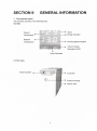
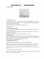
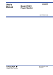
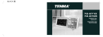
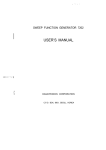
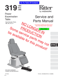
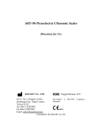
ISO 9001
(
E
Water Chiller
HSO
USER'S MANUAL
CONTENTS
SAFETY ........... .. ..... ... .. .. ... .. ............. ..... .. .. .... ......... 3
SECTIONI
S~CTION
II
GENERAL INFORMATION .................... .... .......... .. 4
SECTIONIII
INSTALLATION ........ .. ........... ............... .. .... ......... .. . 6
SECTIONIV
OPERATION ............................ ..... ...... ... ... ......... .... 8
SECTIONV
MAINTENANCE .. .... .. ........ .. .... ....... .............. .... ..... 9
SECTIONVI
TROUBLESHOOTING ...... .. .. .. .... .................... ... .. 10
2
SECTION I
SAFETY
1. WARNINGS
Make sure you read and understand all instructions and safety precautions Iist in this
manual before installing or operating your unit. lf you have any questions concerning the
operation of your unit or the information in this manual , please contact our Customer Service
Center.
2. PRECAUTIONS
Never place the unit in a location where excessive heat, moisture , or corrosive materials are
present.
The unit construction provides extra protection against the risk of electrical shock by grounding
appropriate metal parts. The extra protection may not function unless the power cord is
connected to a properly grounded outlet. lt is the user's responsibility to assure a proper
ground connection is provided .
Never connect the inlet or outlet fitting to your building water supply or any water pressure
source.
Never use flammable or corrosive fluids with this unit.
Do not use automotive antifreeze. Commercial antifreeze contains silicates that can darnage
the pump seals. Use of automotive antifreeze will void the manufacturer's warranty.
Transport the unit with care. lnclination angle must be less than 60 degrees otherwise the
refrigeration system would be damaged . Sudden jolts or drops can darnage the refrigeration
lines.
Pay attention to all warning Iabeis and never remove warning Iabeis.
Never operate damaged or leaking equipment.
Never operate the unit without cooling fluid in the reservoir.
Always turn off the unit and disconnect the power cord from the power source before
performing any service or maintenance procedures, or before moving the unit.
Never operate equipment with damaged power cords.
Performance of installation , operation , or maintenance procedures other than those described
in this manual may result in a hazardous situation and may void the manufacturer's warranty .
3
SECTION II
GENERAL INFORMATION
1. The controller panel
The controller consists of the following keys .
For H50
Alarm
__:____ _.,., Cooling lndication
Present
Temperature
Setpoint
Running State lndication
Temperature
-+---...
Value lncrease
Backlight On/Off
Value Decrease
2. Front view
Power Swithch •1 1 ----=-~J--H
,
Controller
Pressure Gauge
Hot Air Vent
4
3. Rearview
Electrical Socket.,..,.f-----L4W•
- r;e~'Jrl
,
(1-(9-r
' _ __.., Plumbing Supply
~1.___0_'"_ _ ___.: Plumbing Return
(1__,
• ~--•
Water Drain
4. Specification
Model
H50
Temp . control
range
-5 ~ 35
I'C
Temp . control
PID
mode
Cooling mode
Compressor cooling
Refrigerant
R134A/R22
Temp . Stability /'C
± 0.3
Cooling capacity
500
tW@2s ·c
Reservoir
volume
1.2
/L
Recirculating
DP60
pump
Pressure /MPa
0.05
NOTE: The value of temperature stability is tested in standard operating mode .
5
SECTION 111
INSTALLATION
1. LOCATION
The unit should be located in a clean environment where ambient temperature is between
1o ·c and 35 .C(50 r to 94r) .
Never place the unit in a location where excessive heat, moisture, or corrosive materials are
present.
The unit has an air-cooled refrigeration system . Air is drawn through the front of the unit and
discharged through the rear and side panels . The unit must be positioned so the intake and
discharge are not impeded . A minimum clearance of 3 feet (1 meter) on all vented sides is
necessary for adequate ventilation. lnadequate ventilation will cause a reduction in cooling
capacity and , in extreme cases, compressor failure.
Excessively dusty areas should be avoided and a periodic cleaning schedule should be
instituted (see Section VIII, Maintenance). Optional air filters are available , contact our
Customer Service Center.
The unit will retain its full rated capacity in ambient temperatures up to approximately 25 ·c
(77"F) . Reduce the cooling capacity 1% for every OSC(1 .F) above 25 .C(77 r ), up to a
maximum ambient temperature of 35 .C (94.F ).
2. ELECTRICAL REQUIREMENTS
The unit provides extra protection against the risk of electrical shock by grounding
appropriate meta I parts . The extra protection may not function unless the power cord is
connected to a properly grounded outlet. lt is the user's responsibility to assure a proper
ground connection is provided .
The following power options are available:
Model
VoltageN
H50
220
Frequency
/Hz
50
Phase
1
Circuit
IP
CapacitylA
Degree
6
20
The unit is attached with a piece of European Standard power cord. lt is used to connected
with power supply . Plug the cord into power supply on wall , and plug the rear into electric
socket of the unit. Then the unit is readytobe used.
3. PLUMBING REQUIREMENTS
The plumbing connections are located on the rear of the unit and labeled
"SUPPL Y" and
"RETURN". The connections are 1/2 inch Fernale Pipe Thread . Units with 1/2 inch fittings are
supplied with 3/8 inch and 1/2 inch barbed adapters.
Remave the plastic protective plugs from both plumbing connections. lnstall the barbed
adapters to these connections.
6
Connect the fitting "SUPPL Y" to the hose feeding the inlet of your application . Connect the
fitting
"RETURN " to the hose from the outlet of your application . Clamp all Connections.
Never connect the fitting to your tap water supply or any water pressure source.
NOTE: On units equipped with PO pumps, ensure your plumbing is rated to withstand 90 Psi
at the highest operating temperature .
lt is important to keep the distance between the unit and the instrument being cooled as
short as possible _Tubing should be straight and without bends. lf diameter reductions must be
made, they should be made at the inlet and outlet of your application , not at the chiller.
When you want to change the fitting or keep the chiller idle for a long period , be sure to drain
water out of the water tank . Shut down the unitat first . then put a cup on the ground , and open
water drain outlet to Iet the fluids in reservoir flow out into the cup , at last close water drain
outlet when there is no water in the reservoir.
4. FLUIDS
Never use flammable or corrosive fluids with this unit. Do not use autornative antifreeze.
Commercial antifreeze contains silicates that can darnage the pump seals. Use of autornative
antifreeze will void the manufacturer's warranty.
Fluids should be pure , contain none of impurity such as grains. Otherwise, the impurity will be
prone to darnage the pump. Use of unpurged fluids will void the manufacturer's warranty.
Fluids should be exchanged once every month .
Whenever fluid is exchanged , please kindly add water cleanser into fluid to keep cleaning . As
for Smart SH 150-Series, the volume is 1-2 drops.
7
SECTION IV
OPERATION
1. CONTROLLER
1.1 Change the set point
Press SET to enter into temperature set interface, use
increase the temperature of setpoint.
@
©
@buttons to decrease or
is a transposition key . Press SET again to save
and quit the temperature set interface.
The controllerwill back to normal state if no operation in 1 min .
1.2 Alarm function
A. High-low temperature alarm
Alarm code L-A will be displayed and buzzer alarm when the temperature is lower than the
low temperature Iimit -10 'C
Alarm code H-A will be displayed and buzzer alarm when the temperature is higher than the
high temperature Iimit 50 'C
While alarm , switch off the chiller and restart it to back to normal state.
B. Water Ievei alarm
When the water Ievei is lower than the Iimitation , the water Ievei indicator willlight up and the
buzzer will alarm , system will also cut off the compressor and solenoid valve automatically.
Fullfill the water tank, the compressor will restart after1 minute.
Note: Press any key can stop the buzzer.
2. PRESSURE RELIEF VALVE
The Pressure Relief Valve is used to adjust the unit's fluid flow/pressure.
NOTE: The valve is factory preset for the most common applications and normally requires no
further adjustment. Also , the unit's pump is factory preset not to exceed 60 Psi (4.0Bar) .
Before adjusting the valve turn the unit off. Locate the circular relief valve opening on the rear
of the unit.
Turn the threaded stem fully counterclockwise .
lf the unit is not plumbed to an application , install a loop of hose equipped with a shut-off valve
between the supply and return fittings.
8
Turn the unit on.
Use the pressure gauge to read the relief valve setting.
Back out the threaded stem on the relief valve clockwise. Continue until the gauge indicates 60
psi (48ar) or desired setting.
NOTE: The relief valve may drip if the threaded stem is backed out too far.
3. START UP/SHUT DOWN
Before starting the unit, double-check all electrical and plumbing connections. Have extra
recirculating fluid on hand .
Place the switch located on the rear of the unit to the up position , the controllerwill flash and
the unit will start up .
Place the switch located on the rear of the unit to the down position , the unit will shut down.
NOTE: lf you want to turn on the unitat once after shut down , please wait for 10 seconds.
MAINTENANCE
SECTION V
1. RESERVOIR CLEANING
Periodically inspect the fluid inside the reservoir. lf cleaning is necessary, flush the reservoir
with a cleaning fluid compatible with the circulating system and the cooling fluid .
The cooling fluid should be replaced periodically. Replacement frequency depends on the
operating environment and running time .
Before changing the cooling fluid ensure that it is at a safe handing temperature.
When you want to change the fitting or keep the chiller idle for a long period , be sure to drain
water out of the water tank. Shut down the unit at first, then put a cup on the ground , and
disconnect the fitting "DRAIN" on your application , Iet the fluids in reservoir flow out into the
cup , and disconnect the fitting on our unit.
2. CONDENSER CLEANING
For proper operation , the unit needs to pull substantial amounts of air through a condenser. A
build up of dust or debris on the fins of the condenser will Iead to a loss of cooling capacity.
Optional air filters are available, if need please contact our Customer Service Center.
The lower front of the unit has a one-piece grille assembly. Using your hands gently pry the
assembly off. Use care not to scratch the paint.
Periodic vacuuming of the condenser fins is necessary. The cleaning frequency depends on
the operating environment. Afterinitial installation we recommend a monthly visual inspection
of the condenser. After several months, the cleaning frequency will be established .
Use care cleaning the condenser fins , they can easily bend .
9
3. PO Pumpstrainer cleaning
lf debris is in the system , the strainer will prevent the material from being drawn into the pump
and damaging the pump vanes. A clogged strainer will also cause increased discharge pump
pressures .
Afterinitial installation , the strainer may become clogged with debris and scale. Therefore , the
strainer must be cleaned after the first week of installation . After this first cleaning, we
recommend a monthly visual inspection. After several months , the cleaning frequency will be
established .
PO pumps have a strainer located in the pump. Clean the screen by rinsing it with water.
When the screen is clean , replace it in the strainer, tighten the fitting and replace the panel.
lf water circuit of the unit is equipped with filter system , please change filter cartridge
periodically.
SECTION VI
TROUBLESHOOTING
1. UNIT NOT START
Check the line cord ; ensure it is plugged in .
Check the position of the circuit breaker on the front of the unit. lt ought to be in upper position.
Check the Valtage of power supply.
NOTE: On units with a Low Flow Switch and configured to shut down with a low flow fault,
several starting attempts may be necessary.
2. UNIT NOT CIRCULATE FLUID
Check the water Ievei in reservoir. Fill, if necessary .
Check the instrument being cooled for restrictions in the cooling line .
Check the pump strainer.
Check the pressure gauge, adjust the relief valve as necessary.
3. INADEQUATE TEMPERATURE CONTROL
Verify the setpoint.
lf the temperature continues to rise, make sure your application 's heat Ioad does not exceed
the rated specification.
Make sure the air intake and discharge are not impeded and the ambient temperature does
not exceed +35 ·c .
Make sure the condenser is free of dust and debris .
4. LEAKAGE
Since vapor always contained in the atmosphere , liquid water will occur outside the tube when
the temperature of refrigeration system is lower than the ambient temperature, especially
when the humidity of the atmosphere is high while the set point is lower, the liquid wate r will
get more. To avoid such results , user should turn on the dehumidifier or set the temperature
higher.
10