1
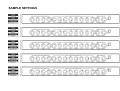
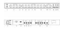
POWERTONE - USER MANUAL
FRONT PANEL FUNCTIONS
[8] PRESENCE : Controls the amount of boost in the upper mid frequency
range of the Gain/Ultra-Gain channel.
[1] INPUTS :
HIGH - Input for standard-level instruments, e.g. guitars with passive pickups.
LOW - Input for high-level instruments, e.g. guitars with high-output passive or
active pickups.
Both inputs may be used for connecting two instruments simultaneously.
[9] BASS, MID & TREBLE : Classic post-distortion passive tone controls that
regulate low, mid and high frequencies respectively, of the Gain/Ultra-Gain
channel. In this channel the tone control circuit is located behind the overdrive
stage, therefore equalising the overdrive tone which results in better control
over the harmonics at high gain settings and a powerfull overdrive sound.
[2] BASS, MID & TREBLE : Classic passive tone controls that regulate low,
mid and high frequencies respectively, of the Clean channel.
[10] RHYTHM VOLUME : When activated (see Footswitch), this control
functions as a master volume and can be preset at a lower (rhythm) volume.
[3] VOLUME : Controls the volume level of the Clean channel.
NOTE: If the Footswitch is not connected, the RHM VOLUME is active.
[4] GAIN : This ‘Dual-Gain’ is a very powerful feature combining Drive and
Gain-Boost in one knob. This has been achieved by controling the amount of
amplification in the Post-EQ Overdrive channel preamp in two stages
simultaneously. Cleaner sound is achieved at lower settings (3 to 5), at middle
settings (5 to 10) medium overdrive occurs which will produce more sustain and
distortion. At high settings (15-30) mega overdrive occurs, adding a lot of of
sustain and compression. Accurate pre and post shaping circuitry prevent the
low-end from getting muddy even at the highest settings.
[11] REV/FX MIX CONTROL : Controls the amount of the Spring Reverb or
Effects signal (see rear panel [5]) mixed with the original dry signal.
[5] VOLUME : Controls the volume level of the Gain channel.
[6] ULTRA-GAIN : This channel has an additional (fifth) gain stage and
therefore delivers extra sustain and compression. Distorted sound is achieved
at lower settings (3 to 6), at higher settings (6 to 15) heavy overdrive occurs
which will produce a more powerfull distortion. At high settings (15-30) ultra
overdrive occurs, adding tons of power, sustain and compression.
[7] VOLUME : Controls the volume level of the Ultra-Gain channel.
NOTE: High gain settings may cause squealing and/or excessive hum and
noise, due to microphonic guitar pick-ups and insufficient screening of circuitry.
[13] DAMPING SWITCH : Switches speaker damping from High to Low. In
High (normal) position the power amp damps the speaker which results in a
more controlled sound. In Low position the power amp’s damping of the
speaker’s cone-movement is minimal, which results in a more open sound.
[13] STANDBY SWITCH : Allows the amp to be placed in standby or active
mode. In standby mode the tubes remain hot, but the amplifier is not
operational.
[14] POWER SWITCH : Turns AC power On and Off. When the switch is Off
the amplifier is completely shut down. When switching the amplifier On, allow
the tubes to get hot before switching to the active mode [13].
POWERTONE - USER MANUAL
REAR PANEL FUNCTIONS
[1] A.C. POWER :
INPUT- Power cord input. The amp is equipped with a worldwide power supply.
It is possible to rewire for selecting one of two voltages, 115 or 230
inside the amp. Either of these voltages will work worldwide with minor
power differences. The amp will work on either 50 or 60 hertz. After
rewiring MAKE SURE FUSES ARE REPLACED WITH PRINTED
RATINGS ON REAR OF AMP.
FUSE - Both fuse and spare fuse are located within the cap of the fuseholder.
Fuse sled can be removed with a screwdriver. If the fuse should fail, IT
MUST BE REPLACED WITH THE SAME TYPE AND VALUE IN
ORDER TO AVOID DAMAGE TO THE AMP AND TO PREVENT
VOIDING THE WARRANTY.
If the amp repeatedly blows fuses, check for a bad power tube. If tubefailure is not the cause, the amp should be taken to a qualified service
center for repair.
WARNING: ONLY A QUALIFIED TECHNICIAN SHOULD ATTEMPT AN
INPUT VOLTAGE CHANGE. PERSONEL INJURY OR EQUIPMENT DAMAGE
MAY OCCUR IF DONE INCORRECTLY.
WARNING: THE FUSE SHOULD ONLY BE REPLACED WHEN THE
POWER CORD HAS BEEN DISCONNECTED FROM ITS POWER SOURCE.
[2] CHANNELS SWITCH : Selects the Clean, the Gain and the Ultra-Gain
channel if the Footswitch is not connected.
[3] FOOTSWITCH CONNECTOR : Provides an input for the FOOTSWITCH
and automatically disconnects the Channels Switch [2].
THE FS-5 FOOTSWITCH
The Footswitch (included) is equipped with five switches:
- three CHANNEL switches for selecting the Clean channel, the Gain channel
or the Ultra-Gain channel (red LED indicators).
- a SOLO/RHYTHM switch for activating (green LED on) or bypassing the
RHYTHM VOLUME control [11].
- a REV/FX switch for switching the Parallel Effects Loop on/off (yellow LED).
Thus functioning as a Reverb on/off switch or, if an effects unit is plugged in to
this loop, as an Effects on/off switch [5].
[4] PARALLEL EFFECTS LOOP SEND (TO FX) : This jack provides a
buffered mono output from the preamp and can be used in conjunction with the
RETURN (FROM FX) [5] jack as a patch point for external effects units. (see
CONNECTION DIAGRAM page.)
[5] PARALLEL EFFECTS LOOP RETURN (FROM FX) : This jack disconnects
the internal spring reverb and inputs external (effects) signal via the REV/FX
MIX control at the front panel directly to the power amp where it is mixed with
the original dry signal from the preamp.
IF THIS LOOP IS USED, DIRECT SIGNAL MUST BE TAKEN OFF THE
EFFECTS UNITS SIGNAL FOR EXAMPLE WITH ITS DRY/WET MIX
CONTROL.
[6] SERIAL EFFECTS LOOP SEND (TO FX) : This jack provides a buffered
mono output from the preamp and can be used in conjunction with the
RETURN (FROM FX) [7] jack as a patch point for external effects units. (see
CONNECTION DIAGRAM page.)
[7] SERIAL EFFECTS LOOP RETURN (FROM FX) : This jack inputs external
(direct+effects) signal directly to the power amp and automatically disconnects
the preamp.
NOTE: The EFFECT LOOPS operate on a -10dBV SIGNAL LEVEL which
guarantees compatibility with both instrument-level effects like floor-pedals and
guitar-processors, as well as line-level effects like professional 19 inch rack
mount devices.
NOTE: If the connecting of an effects unit to the POWERTONE causes hum, a
ground-loop may be the reason for it. This ground-loop may be eliminated by
isolating or disconnecting the effects units earth from the mains sockets earth.
[8] SPEAKER OUTPUT JACKS : Provided for connection of speaker(s) or
speaker cabinet(s) with a minimum total impedance of 4, 8 or 16 ohms.
[9] RECORDING OUTPUT : ThIs jack provides a mono output from the power
amp and includes Reverb and External Effects signals. The signal is derived
from the speaker output and filtered by a special Speaker Simulating Filter
which simulates the sound coming from the speaker. Now the signal can be fed
directly to a recording or sound reinforcement mixer while the amp will sound
as if it is miked.
POWER TUBE OPTIONS
Due to special bias control circuitry, the POWERTONE is able to accept almost
any type of power tube, for example: EL34, 6CA7, 6L6, 6550, KT66, KT77,
KT88, KT90, KT100.
Also, the POWERTONE is provided with two seperate bias control trimmers (on
the PC board), one for the inner two power tubes and one for the outer two
power tubes, thus enabling the use of mixed sets of power tubes (two + two).
So for example the two outer tubes may be EL34’s while the two inner tubes
are 6L6’s or 6550’s.
Each type of power tube has its own distinctive sound character, therefore
changing to a different type (or mix of types) of power tubes also changes your
amp’s overall sound.
REPLACING TUBES
•
•
•
•
•
SAFETY FIRST: DISCONNECT THE POWER CORD FROM ITS POWER
SOURCE AND LET HOT TUBES COOL.
CHECK THE ‘TUBE LOCATION DIAGRAM’ ON THE CHASSIS FOR THE
CORRECT TYPE NUMBERS AND LOCATIONS.
REPLACE TUBES ONLY WITH ORIGINAL KOCH HIGH QUALITY
TUBES. (IF OTHER TUBES ARE USED THE WARRANTEE OBLIGATION
EXPIRES)
BEFORE REPLACING THE POWER TUBES, REMOVE THE CE SAFETY
CAP FIRST.
AFTER REPLACING THE POWER TUBES, PUT THE CE SAFETY CAP
BACK IN PLACE.
NOTE: ALWAYS HAVE THE AMP REBIASED AFTER PEPLACING THE
POWER TUBES. BIASING INSTRUCTIONS CAN BE FOUND INSIDE THE
AMP.
REBIASING THE AMP IS NOT NECCESSARY ONLY IF KOCH POWER
TUBES ARE USED WITH THE SAME TYPE AND BIAS-CLASS NUMBER.
Preamp and Power tubes wear out and have to be changed from time to time to
maintain the amps best performance. Tubes behave like strings, they loose
highs, lows and dynamics and after a period of time they have to be changed.
Exactly when is hard to say but this is an indication: if you play almost every
day change tubes each year, if you play once or twice a week change tubes
every 2-3 years.
Tubes rarely fail. If they are bad, these might be the symptoms:
PREAMP TUBES (ECC83/12AX7A, 7025/12AX7WA):
- Microphonic whistling or squealing on one or both channels.
- No or low amp volume on one or both channels.
- Excessive noise on one or both channels.
POWER TUBES:
- Loud crackling that is not affected by front panel controls.
- Intermittent or regular blowing fuses.
- Weird amp ‘distorting’.
- Hum.
Changing a tube is a simple and quick fix for most problems in your amp.
In case of failure, just one or more POWER TUBES can be replaced without
rebiasing only if KOCH tubes with the SAME TYPE AND BIAS-CLASS
NUMBER are used.
If power tubes with a different or unknown bias-class number are used for
replacement, BOTH TUBES (the two inner or the two outer tubes) have to be
replaced and the amp has to be REBIASED.
Please always use four or two + two (see above) matched replacement power
tubes to obtain the amps best performance.
SAMPLE SETTINGS
CONNECTION DIAGRAM
TECHNICAL SPECIFICATIONS
INPUT IMPEDANCES
Input HIGH
Input LOW
From FX
1 M ohms
136 K ohms
100 K ohms
OUTPUT IMPEDANCES
To FX
1K ohms
SIGNAL LEVELS
Effect Loops
-10 dBV
TUBES
Preamp
2x 12AX7A/ECC83
1x 12AX7WA/7025
1x 12AX7A/ECC83
EL34 / 6L6 / 6550 (see text)
Power amp
OUTPUT POWER
MAINS
120 Watts in 4, 8 and 16 ohms
230VAC, 50Hz
115VAC, 60Hz
250 Watts
250 Watts