1
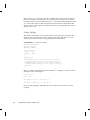
Writing Device Drivers
Sun Microsystems, Inc.
2550 Garcia Avenue
Mountain View, CA 94043-1100
U.S.A.
Part No: 805-3024–10
October 1998
Copyright Years(s) Sun Microsystems, Inc. 901 San Antonio Road, Palo Alto, California 94303-4900 U.S.A. All rights reserved.
This product or document is protected by copyright and distributed under licenses restricting its use, copying, distribution, and
decompilation. No part of this product or document may be reproduced in any form by any means without prior written authorization of
Sun and its licensors, if any. Third-party software, including font technology, is copyrighted and licensed from Sun suppliers.
Parts of the product may be derived from Berkeley BSD systems, licensed from the University of California. UNIX is a registered
trademark in the U.S. and other countries, exclusively licensed through X/Open Company, Ltd.
Sun, Sun Microsystems, the Sun logo, SunDocs, Java, the Java Coffee Cup logo, and Solaris are trademarks, registered trademarks, or
service marks of Sun Microsystems, Inc. in the U.S. and other countries. All SPARC trademarks are used under license and are trademarks
or registered trademarks of SPARC International, Inc. in the U.S. and other countries. Products bearing SPARC trademarks are based upon
an architecture developed by Sun Microsystems, Inc.
The OPEN LOOK and SunTM Graphical User Interface was developed by Sun Microsystems, Inc. for its users and licensees. Sun
acknowledges the pioneering efforts of Xerox in researching and developing the concept of visual or graphical user interfaces for the
computer industry. Sun holds a non-exclusive license from Xerox to the Xerox Graphical User Interface, which license also covers Sun’s
licensees who implement OPEN LOOK GUIs and otherwise comply with Sun’s written license agreements.
RESTRICTED RIGHTS: Use, duplication, or disclosure by the U.S. Government is subject to restrictions of FAR 52.227–14(g)(2)(6/87) and
FAR 52.227–19(6/87), or DFAR 252.227–7015(b)(6/95) and DFAR 227.7202–3(a).
DOCUMENTATION IS PROVIDED “AS IS” AND ALL EXPRESS OR IMPLIED CONDITIONS, REPRESENTATIONS AND WARRANTIES,
INCLUDING ANY IMPLIED WARRANTY OF MERCHANTABILITY, FITNESS FOR A PARTICULAR PURPOSE OR
NON-INFRINGEMENT, ARE DISCLAIMED, EXCEPT TO THE EXTENT THAT SUCH DISCLAIMERS ARE HELD TO BE LEGALLY
INVALID.
Copyright Years(s) Sun Microsystems, Inc. 901 San Antonio Road, Palo Alto, Californie 94303-4900 Etats-Unis. Tous droits réservés.
Ce produit ou document est protégé par un copyright et distribué avec des licences qui en restreignent l’utilisation, la copie, la
distribution, et la décompilation. Aucune partie de ce produit ou document ne peut être reproduite sous aucune forme, par quelque
moyen que ce soit, sans l’autorisation préalable et écrite de Sun et de ses bailleurs de licence, s’il y en a. Le logiciel détenu par des tiers, et
qui comprend la technologie relative aux polices de caractères, est protégé par un copyright et licencié par des fournisseurs de Sun.
Des parties de ce produit pourront être dérivées du système Berkeley BSD licenciés par l’Université de Californie. UNIX est une marque
déposée aux Etats-Unis et dans d’autres pays et licenciée exclusivement par X/Open Company, Ltd.
Sun, Sun Microsystems, le logo Sun, SunDocs, Java, le logo Java Coffee Cup, et Solaris sont des marques de fabrique ou des marques
déposées, ou marques de service, de Sun Microsystems, Inc. aux Etats-Unis et dans d’autres pays. Toutes les marques SPARC sont utilisées
sous licence et sont des marques de fabrique ou des marques déposées de SPARC International, Inc. aux Etats-Unis et dans d’autres pays.
Les produits portant les marques SPARC sont basés sur une architecture développée par Sun Microsystems, Inc.
TM
L’interface d’utilisation graphique OPEN LOOK et Sun
a été développée par Sun Microsystems, Inc. pour ses utilisateurs et licenciés.
Sun reconnaît les efforts de pionniers de Xerox pour la recherche et le développement du concept des interfaces d’utilisation visuelle ou
graphique pour l’industrie de l’informatique. Sun détient une licence non exclusive de Xerox sur l’interface d’utilisation graphique Xerox,
cette licence couvrant également les licenciés de Sun qui mettent en place l’interface d’utilisation graphique OPEN LOOK et qui en outre
se conforment aux licences écrites de Sun.
CETTE PUBLICATION EST FOURNIE “EN L’ETAT” ET AUCUNE GARANTIE, EXPRESSE OU IMPLICITE, N’EST ACCORDEE, Y
COMPRIS DES GARANTIES CONCERNANT LA VALEUR MARCHANDE, L’APTITUDE DE LA PUBLICATION A REPONDRE A UNE
UTILISATION PARTICULIERE, OU LE FAIT QU’ELLE NE SOIT PAS CONTREFAISANTE DE PRODUIT DE TIERS. CE DENI DE
GARANTIE NE S’APPLIQUERAIT PAS, DANS LA MESURE OU IL SERAIT TENU JURIDIQUEMENT NUL ET NON AVENU.
Please
Recycle
Contents
Preface
1.
xxi
SunOS Kernel and Device Tree 1
What Is the Kernel? 1
Multithreading Considerations
Virtual Memory
Special Files
2
2
2
Dynamic Loading of Kernel Modules 3
Overview of the Solaris 7 DDI/DKI 3
Device Tree
4
Example Device Tree
5
Displaying the Device Tree
7
Binding a Driver to a Device Node
2.
8
Hardware Overview 11
SPARC Processor Issues
11
SPARC Data Alignment 11
SPARC Structure Member Alignment 12
SPARC Byte Ordering
12
SPARC Register Windows 12
SPARC Floating-Point Operations
13
Contents
iii
SPARC Multiply and Divide Instructions 13
SPARC Architecture Manual 13
x86 Processor Issues
13
x86 Data Alignment 13
x86 Structure Member Alignment 13
x86 Byte Ordering
14
x86 Floating-Point Operations
14
x86 Architecture Manuals 14
Store Buffers
14
System Memory Model
15
Total Store Ordering (TSO) 15
Partial Store Ordering (PSO)
Bus Architectures
16
Device Identification
16
Interrupts 17
Bus Specifics
17
PCI Local Bus 17
PCI Address Domain
19
SBus 22
VMEbus 24
ISA Bus 25
EISA Bus 26
MCA Bus 27
Device Issues 27
Timing-Critical Sections 27
Delays 28
Internal Sequencing Logic
Interrupt Issues
iv
28
Writing Device Drivers ♦ October 1998
28
15
Byte Ordering
29
Device Attribute Representations
PROM on SPARC Machines
Open Boot PROM 3.x
30
30
31
Reading and Writing 34
3.
Overview of SunOS Device Drivers 37
What Is a Device Driver? 37
Types of Device Drivers 37
Block Device Drivers
38
Standard Character Device Drivers
38
STREAMS Drivers 39
Bus Address Spaces
40
Address Mapping Setup 40
Data Access Functions 42
Example Device Registers 44
Device Register Structure
Driver Interfaces
47
Entry Points
47
45
Driver Structure Overview
49
Callback Functions 50
Interrupt Handling
51
Device-Interrupt Cookies 51
Block-Interrupt Cookies 52
Driver Context
52
Printing Messages
52
Dynamic Memory Allocation
53
Software State Management 54
Software State Structure
54
Contents v
Software State Management Routines
Properties
55
55
prop_op(9E) 58
Driver Layout
59
Header Files
Source Files
60
60
Configuration Files
60
64-Bit-Safe Device Drivers
60
C Language and Compiler Modes
Compiler Modes
61
Function Prototypes
Keywords
4.
61
61
62
Multithreading 65
Threads
65
User Threads
65
Kernel Threads
66
Multiprocessing Changes Since the SunOS 4.1 System 66
Locking Primitives 68
Storage Classes of Driver Data 68
Mutual-Exclusion Locks 68
Readers/Writer Locks 70
Semaphores
70
Thread Synchronization 70
Condition Variables
70
cv_timedwait(9F) 73
cv_wait_sig( ) 74
cv_timedwait_sig() 75
Choosing a Locking Scheme 75
vi
Writing Device Drivers ♦ October 1998
5.
Autoconfiguration 77
Autoconfiguration Overview 77
Autoconfiguration Additions to the State Structure
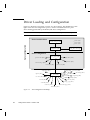
Driver Loading and Configuration
Data Structures
77
78
79
modlinkage Structure
modldrv Structure
79
dev_ops Structure
79
cb_ops Structure
79
80
Loadable Driver Interface 81
Device Configuration 83
Instance Numbers
84
identify( ) 84
probe( ) 84
attach()
87
detach()
92
getinfo() 94
6.
Interrupt Handlers
97
Interrupt Handler Overview
Interrupt Specification
97
97
Interrupt Number 98
Interrupt Block Cookies 98
Bus Interrupt Levels
98
High-Level Interrupts 98
Types of Interrupts 99
Vectored Interrupts 99
Polled Interrupts 99
Software Interrupts
100
Contents vii
Registering Interrupts 101
Responsibilities of an Interrupt Handler
102
Interrupt Handling Additions to the State Structure
104
Handling High-Level Interrupts 104
High-level Mutexes 105
High-Level Interrupt Handling Example 105
7.
DMA 109
DMA Model 109
Types of Device DMA 110
Bus-Master DMA
110
Third-party DMA
110
First-party DMA
111
Types of Host Platform DMA
111
DMA Software Components: Handles, Windows, and Cookies 111
Scatter-Gather 112
DMA Operations
112
Bus-Master DMA
First-Party DMA
112
113
Third-Party DMA
DMA Attributes
Object Locking
113
114
117
Allocating a DMA Handle 117
Allocating DMA Resources
118
Determining Maximum Burst Sizes
Programming the DMA Engine
Freeing the DMA Resources
Freeing the DMA Handle
Canceling DMA Callbacks
viii
Writing Device Drivers ♦ October 1998
123
124
124
121
122
Synchronizing Memory Objects 125
DMA Windows 127
State Structure
128
Allocating Private DMA Buffers
8.
130
Power Management 133
Power Management Overview
Device Power Management
133
134
System Power Management 134
Power Management Additions to the State Structure
135
Device Power Management Model 135
Components 135
Idleness 136
Power Levels 136
Dependency 136
Policy 137
Device Power Management Interfaces
137
Entry Points Used by Device Power Management 139
System Power Management Model
Autoshutdown Threshold
Busy State
142
143
143
Hardware State 143
Policy 144
Entry Points Used by System Power Management
Device Access
144
147
Power Management Flow of Control 148
Device Power Management Flow of Control for Component Zero
148
Device Power Manangement Flow of Control for Components Other
Than Component Zero 149
Contents ix
9.
Drivers for Character Devices
151
Character Driver Structure Overview
151
Character Driver Device Access 151
Entry Points 152
Autoconfiguration
154
Controlling Device Access
155
open(9E) 155
I/O Request Handling
User Addresses
Vectored I/O
157
157
157
Synchronous Versus Asynchronous I/O
Data Transfer Methods
159
160
Mapping Device Memory 165
segmap(9E) 166
Multiplexing I/O on File Descriptors
166
Adding Polling to the State Structure
167
chpoll(9E) 167
Miscellaneous I/O Control
ioctl(9E)
169
169
I/O Control Support for 64-Bit Capable Device Drivers 171
10.
Drivers for Block Devices 173
Block Driver Structure Overview
173
Block Driver Device Access 173
File I/O
174
Block Driver Additions to the State Structure
Entry Points 175
Autoconfiguration
176
Controlling Device Access 178
x
Writing Device Drivers ♦ October 1998
175
open(9E)
178
179
close(9E)
Data Transfers
180
strategy(9E)
buf Structure
180
181
Synchronous Data Transfers
182
Asynchronous Data Transfers
Miscellaneous Entry Points
186
189
dump(9E) 189
print(9E)
11.
190
Mapping Device or Kernel Memory
Memory Mapping Operations
Exporting the Mapping
devmap()()
191
191
191
192
Associating Device Memory With User Mappings
192
Associating Kernel Memory With User Mappings
194
Device Mapping Additions to the State Structure
194
Allocating Kernel Memory for User Access 194
Exporting Kernel Memory to Applications 196
Freeing Kernel Memory Exported for User Access
12.
198
Device Context Management 199
What Is a Device Context? 199
Context Management Model 199
Multiprocessor Considerations
201
Context Management Additions to the State Structure
201
Context Management Operation 202
devmap_callback_ctl Structure
202
Associating User Mappings With Driver Notifications
203
Contents xi
Managing Mapping Accesses 204
Device Context Management Entry Points 205
13.
SCSI Target Drivers 213
SCSI Target Driver Overview
213
Reference Documents 214
Sun Common SCSI Architecture Overview
General Flow of Control
215
SCSA Functions 217
SCSA Compatibility Functions 218
SCSI Target Drivers 219
Hardware Configuration File 219
Declarations and Data Structures 220
Autoconfiguration
222
Resource Allocation
228
Building and Transporting a Command 229
Building a Command 230
Setting Target Capabilities
Transporting a Command
230
231
Command Completion 232
Reuse of Packets
233
Auto-Request Sense Mode 233
Dump Handling
14.
235
SCSI Host Bus Adapter Drivers 239
SCSI HBA Driver Overview
239
SCSA Interface 240
HBA Transport Layer 241
SCSA HBA Interfaces
241
SCSA HBA Entry Point Summary
xii
Writing Device Drivers ♦ October 1998
242
214
SCSA HBA Data Structures 243
Per-Target Instance Data 247
Transport Structure Cloning (optional)
248
SCSA HBA Functions 250
HBA Driver Dependency and Configuration Issues 251
HBA Configuration Properties 252
Declarations and Structures
253
HBA Additions to the State Structure
254
Module Initialization Entry Points 254
Autoconfiguration Entry Points
SCSA HBA Entry Points
256
260
Target Driver Instance Initialization
Resource Allocation
261
263
Command Transport 272
Capability Management 278
Abort and Reset Management
Driver Installation
283
284
Hardware Configuration File
284
Installing the Driver 285
x86 Target Driver Configuration Properties
15.
285
Loading and Unloading Drivers 287
Preparing for Installation
287
Module Naming 287
Compiling and Linking the Driver
288
Writing a Hardware Configuration File 288
Installing and Removing Drivers
288
Copying the Driver to a Module Directory
289
Running add_drv add_drv(1M) 289
Contents xiii
Removing the Driver
290
Loading Drivers 290
Getting the Driver Module’s ID
290
Unloading Drivers 291
Driver Packaging
291
Package Postinstall 291
Package Postremove
16.
292
Debugging 295
Machine Configuration 295
Setting Up a tip(1) Connection 295
Preparing for Disasters
297
Coding Hints 300
Process Layout for Sun4m, Sun4c, Sun4d, and x86 Platforms 300
Process Layout for Sun4u Platforms 301
System Support 301
Conditional Compilation and Variables
303
volatile and _depends_on 304
Debugging Tools
304
/etc/system 304
moddebug 305
modload and modunload 305
Saving System Core Dumps
adb and kadb
306
306
Example: adb on a Core Dump
317
Example: kadb on a Deadlocked Thread
Testing
322
Configuration Testing
Functionality Testing
xiv
Writing Device Drivers ♦ October 1998
322
322
319
Error Handling
323
Stress, Performance, and Interoperability Testing
323
DDI/DKI Compliance Testing 324
Installation and Packaging Testing
324
Testing Specific Types of Drivers 324
A.
Converting a SunOS 4.1 Device Driver to SunOS 5.7
327
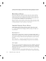
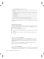
Before Starting the Conversion 327
Review Existing Functionality 327
Read the Manual 328
ANSI C Compliance
328
Development Environment
328
DDI/DKI 328
Avoid Using Non-DDI/DKI Interfaces
328
UNIX System V Release 4 329
Development Tools
329
Debugging Tools
329
ANSI C Features
330
Header Files
330
Summary of Changes
331
Autoconfiguration Changes
Changes to /devices
331
332
Changes to/dev 332
Multithreading Changes
Locking Changes
333
Interrupt Changes
DMA Changes
332
337
337
Conversion Notes 338
identify(9E)
338
Contents xv
probe(9E)
339
attach(9E) 339
getinfo(9E) 340
open(9E) 340
psize( ) 340
read(9E) and write(9E) 341
ioctl(9E)
341
342
strategy(9E)
mmap(9E) 342
chpoll(9E) 342
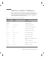
SunOS 4.1 to SunOS 5.7 Differences
343
B.
Interface Transition List 353
C.
Summary of Solaris 7 DDI/DKI Services
buf(9S) Handling
356
Copying Data 359
Device Access 361
Device Configuration 361
Device Information 362
DMA Handling 364
Flow of Control 371
Interrupt Handling
372
Kernel Statistics 374
Memory Allocation
376
Memory Space Access 378
Common Device Access Functions
Polling 386
Power Management 387
Printing System Messages
xvi
Writing Device Drivers ♦ October 1998
388
382
355
Process Signaling 390
Properties
390
Register and Memory Mapping 396
Device Context Management
PCI Configuration
I/O Port Access
398
399
400
SCSI and SCSA 404
Soft State Management 410
String Manipulation 411
System Information 413
Thread Synchronization 414
Timing 420
uio(9S) Handling
421
Utility Functions 422
D.
Sample Driver Source Code
Sample Drivers
E.
429
Driver Code Layout Structure
Header Files
xx.c Files
431
431
432
driver .conf Files
F.
429
435
Making a Device Driver 64-Bit Ready
437
How 64-Bit Drivers Differ From 32-Bit Drivers
437
C Language Data Type Models: LP64 and ILP32 437
Overview of Driver-Specific Issues
General Conversion Steps
438
439
Convert Driver Code to Be 64-Bit Clean 439
Update Data Structures to Preserve 32-Bit Data in Register Layouts 441
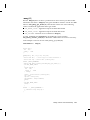
Contents xvii
Check Use of Derived Types That Change Size Between 32-Bit and
64-Bit Environments 441
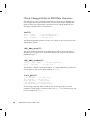
Change Common Access Functions to Fixed-Width Versions 442
Modify Routines That Handle Data Sharing
Check Changed Fields in DDI Data Structures
443
448
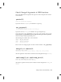
Check Changed Arguments of DDI Functions 449
Convert Well-Known Ioctl Interfaces
Data Structure Macros
451
452
How Structure Macros Work
453
Declaring and Initializing Structure Handles 454
Operations on Structure Handles 455
Other Operations
456
When to Use Structure Macros
G.
456
Advanced Topics 459
Multithreading
459
Lock Granularity 459
Avoiding Unnecessary Locks
Locking Order
460
460
Scope of a Lock 461
Potential Panics
461
Sun Disk Device Drivers
462
Disk I/O Controls 462
Disk Performance
463
SCSA 464
Global Data Definitions
464
Tagged Queuing 465
Untagged Queueing 466
H.
xviii
Converting Device Drivers to Support Hotplugging 467
Writing Device Drivers ♦ October 1998
Introduction
467
Overview of Hotplugging
468
Hot Removal With No Replacement
Hot Insertion
468
468
Hot Removal Followed by Insertion
Solaris Hotplugging Driver Issues
Hot Removal
469
Hot Insertion
470
469
469
Hotplug-Capable Device Driver Development 470
D_HOTPLUG Flag 470
Detach Entry Point 470
Attach Entry Point 474
Special Issues With SCSI HBA Drivers 475
Device Driver Testing
Unloading
476
476
Suspend/Resume Testing
476
Conclusion 477
Contents xix
xx
Writing Device Drivers ♦ October 1998
Preface
Writing Device Drivers provides information on developing device drivers for
character-oriented devices, block-oriented devices, and small computer system
interface (SCSI) target devices. This book discusses the development of a
dynamically loadable and unloadable, multithreaded reentrant device driver
applicable to all architectures that conform to the SolarisTM 7 DDI/DKI. A common
driver programming approach is taken so that drivers can be written without
concern for platform-specific issues such as endianness and data ordering.
Who Should Use This Book
The audience for this book is UNIX® programmers familiar with UNIX device
drivers. Several overview chapters at the beginning of the book provide background
information for the detailed technical chapters that follow, but they are not intended
as a general tutorial or text on device drivers.
How This Book Is Organized
This book is organized into the following chapters.
4 Chapter 1,provides an overview of the SunOSTM kernel and the manner in which it
represents devices as nodes in a device tree.
4 Chapter 2 discusses multiplatform hardware issues related to device drivers.
Preface xxi
4 Chapter 3 gives an outline of the kinds of device drivers and their basic structure.
It points out the common data access routines and concludes with an illustrated
roadmap of common driver entry points and structures.
4 Chapter 4 describes the mechanisms of the SunOS multithreaded kernel that are of
interest to driver writers.
4 Chapter 5 details the support a driver must provide for autoconfiguration.
4 Chapter 6 describes the interrupt handling mechanisms. These include registering,
servicing, and removing interrupts.
4 Chapter 7 describes direct memory access (DMA) and the DMA interfaces.
4 Chapter 8 covers the interfaces for Power ManagementTM , a framework designed
to regulate and reduce the power consumed by computer systems and devices.
4 Chapter 9 describes the structure and functions of a driver for a character-oriented
device.
4 Chapter 10 describes the structure and functions of a driver for a block-oriented
device.
4 Chapter 11 describes the set of interfaces that allow device drivers to manage
access to memory, control the context of user processes accessing a device, and
take advantage of large data transfers using new MMU hardware.
4 Chapter 12 describes the set of interfaces that allow device drivers to manage user
access to devices.
4 Chapter 13 outlines the Sun Common SCSI Architecture and describes the
additional requirements of SCSI target drivers.
4 Chapter 14 explains how to write a SCSI Host Bus Adapter (HBA) driver using the
Sun Common SCSI Architecture (SCSA).
4 Chapter 15 provides information on compiling and linking a driver, and for
installing it in the system.
4 Chapter 16 gives coding suggestions, debugging hints, a simple adb/kadb
tutorial, and some hints on testing the driver.
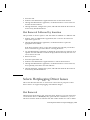
4 Appendix A gives hints on converting SunOS 4.1 drivers to SunOS 5.7.
4 Appendix B presents a list of DDI/DKI data access interface functions that have
changed from Solaris 2.6 to Solaris 7. It also presents data access functions new to
Solaris 7.
4 Appendix C summarizes, by topic, the kernel functions device driver can use.
4 Appendix D displays a list of sample drivers, and the location of the sample code
in the DDK.
4 Appendix E presents header files and an outline of xx.c source code samples for a
typical driver.
4 Appendix F provides guidelines for updating a device driver to run in a 64-bit
environment.
xxii
Writing Device Drivers ♦ October 1998
4 Appendix G presents a collection of optional topics.
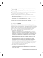
Related Books
For detailed reference information about the device driver interfaces, see the man
page sections 9, 9E (entry points), 9F (functions), and 9S (structures). For information
on hardware issues and other driver-related issues, the following books may be
helpful.
4 Writing PCMCIA Device Drivers, SunSoft, 1997.
4 Application Packaging Guide, SunSoft, 1996.
4 Streams Programming Guide, SunSoft, 1996.
4 Multithreading Programming Guide, SunSoft 1996.
4 SPARC Architecture Manual, Version 9, Sun Microsystems Computer Company,
1996.
4 80386 Programmer’s Reference Manual, Intel Corporation, 1986. ISBN 1-55512-022-9.
4 i486 Microprocessor Hardware Reference Manual, Intel Corporation, 1990. ISBN
1-55512-112-8.
4 Pentium Processor User’s Manual - Volume 3: Architecture and Programming
Manual, Intel Corporation, 1993. ISBN 1-55512-195-0.
4 Open Boot PROM Toolkit User’s Guide, Sun Microsystems Computer Company,
1996.
4 Dynamic Reconfiguration AnswerBook
4 PCI Special Internet Group Web Site:
http://www.pcisig.com/contents.html
4 Advanced Configuration and Power Interface (ACPI) Web Site:
http://www.teleport.com/~acpi
Ordering Sun Documents
The SunDocsSM program provides more than 250 manuals from Sun Microsystems,
Inc. If you live in the United States, Canada, Europe, or Japan, you can purchase
documentation sets or individual manuals using this program.
For a list of documents and how to order them, see the catalog section of the
SunExpressTM Internet site at http://www.sun.com/sunexpress.
xxiii
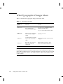
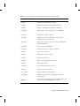
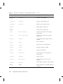
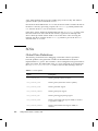
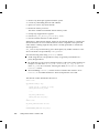
What Typographic Changes Mean
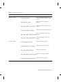
Table P–1 describes the typographic changes used in this book.
TABLE P–1
Typographic Conventions
Typeface or
Symbol
Meaning
Example
AaBbCc123
The names of commands,
files, and directories;
on-screen computer output
di_add_intr( ) registers a device
interrupt with the system.
add_drv adds a driver to the system.
AaBbCc123
What you type, contrasted
with on-screen computer
output
machine_name% su
Password:
AaBbCc123
Command-line placeholder:
number is the number of the interrupt
to register.
replace with a real name or
value
AaBbCc123
Book titles, new words or
terms, or words to be
emphasized
Read Chapter 6 in Writing Device
Drivers. A mutual exclusion lock is....
Note - The term “x86” refers to the Intel 8086 family of microprocessor chips,
including the Pentium and Pentium Pro processors and compatible microprocessor
chips made by AMD and Cyrix. In this document the term “x86” refers to the overall
platform architecture, whereas “Intel Platform Edition” appears in the product name
of x86 products.
xxiv
Writing Device Drivers ♦ October 1998
CHAPTER
1
SunOS Kernel and Device Tree
This chapter provides an overview of the SunOS kernel and the manner in which it
represents devices as nodes in a device tree. It covers general kernel structure and
function, and the Solaris 7 Device Driver Interface/Driver Kernel Interface (DDI/
DKI). In addition, driver binding to device nodes is discussed in relation to both
specific and generic device names.
What Is the Kernel?
The SunOS kernel is a program that manages system resources. It insulates
applications from the system hardware and provides them with essential system
services such as input/output (I/O) management, virtual memory, and scheduling.
The kernel consists of object modules that are dynamically loaded into memory
when needed.
The kernel provides a set of interfaces for applications to use called system calls.
System calls are documented in the Solaris 2.7 Reference Manual (see Intro(2)). The
function of some system calls is to invoke a device driver to perform I/O. Device
drivers are loadable modules that insulate the kernel from device hardware and
manage data transfers.
The remainder of this book discusses the specifics of device drivers. For details on
compiling and installing a device driver, see Chapter 15. The following sections
provide additional high-level information on the SunOS operating system.
1
Multithreading Considerations
In most UNIX systems, the process is the unit of execution. In the SunOS 5.7 system,
a thread is the unit of execution. A thread is a sequence of instructions executed
within a program. A process consists of one or more threads. There are two types of
threads: application threads, which run in user space, and kernel threads, which run
in kernel space.
The kernel is multithreaded (MT). Many kernel threads can be running kernel code,
and may be doing so concurrently on a multiprocessor (MP) machine. Kernel threads
may also be pre-empted by other kernel threads at any time. This is a departure from
the traditional UNIX model where only one process can run kernel code at any one
time, and that process is not pre-emptable (though it is interruptible).
The multithreading of the kernel imposes some additional restrictions on the device
drivers. For more information on multithreading considerations, see Chapter 4and
Appendix G.
Virtual Memory
A complete overview of the SunOS virtual memory (VM) system is beyond the scope
of this book, but two virtual memory terms of special importance are used when
discussing device drivers: virtual address and address space.
4 Virtual address – A virtual address is an address that is mapped by the memory
management unit (MMU) to a physical hardware address. All addresses directly
accessible by the driver are kernel virtual addresses; they refer to the kernel address
space.
4 Address space – An address space is a set of virtual address segments, each of which
is a contiguous range of virtual addresses. Each user process has an address space
called the user address space. The kernel has its own address space called the kernel
address space.
Special Files
In UNIX, devices are treated as files. They are represented in the file system by
special files. These files are advertised by the device driver and commonly reside in
the /devices directory hierarchy.
Special files may be of type block or character. The type indicates which kind of device
driver operates the device.
Associated with each special file is a device number. This consists of a major number
and a minor number. The major number identifies the device driver associated with
the special file. The minor number is created and used by the device driver to further
identify the special file. Usually, the minor number is an encoding that identifies the
2
Writing Device Drivers ♦ October 1998
device the driver should access and the type of access to perform. The minor
number, for example, could identify a tape device requiring backup and also specify
whether the tape needs to be rewound when the backup operation is complete.
Dynamic Loading of Kernel Modules
Kernel modules are loaded dynamically as references are made to them. For example,
when a device special file is opened (see open(2)), the corresponding driver is loaded
if it is not already in memory. Device drivers must provide support for dynamic
loading. See Chapter 5, for more details about the loadable module interface.
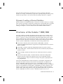
Overview of the Solaris 7 DDI/DKI
In System V Release 4 (SVR4), the interface between device drivers and the rest of
the UNIX kernel has been standardized and documented in Section 9 of the of the
Solaris 2.7 Reference Manual. The reference manual documents driver entry points,
driver-callable functions and kernel data structures used by device drivers. These
interfaces, known collectively as the Solaris 7 Device Driver Interface/Driver Kernel
Interface (Solaris 7 DDI/DKI), are divided into the following subdivisions:
4 Device Driver Interface/Driver Kernel Interface (DDI/DKI) – Includes
architecture-independent interfaces supported on all implementations of System V
Release 4 (SVR4).
4 Solaris DDI – Includes architecture-independent interfaces specific to Solaris.
4 Solaris SPARC DDI – Includes SPARC Instruction Set Architecture (ISA) interfaces
specific to Solaris.
4 Solaris x86 DDI– Includes x86 Instruction Set Architecture interfaces specific to
Solaris.
4 Device Kernel Interface (DKI) – Includes DKI-only architecture-independent
interfaces specific to SVR4. These interfaces may not be supported in future
releases of System V. Only two interfaces belong to this group: segmap(9E) and
hat_getkpfnum(9F).
The Solaris 7 DDI/DKI, like its SVR4 counterpart, is intended to standardize and
document all interfaces between device drivers and the kernel. In addition, the
Solaris 7 DDI/DKI is designed to allow source compatibility for drivers on any
SunOS 5.7-based machine, regardless of the processor architecture (such as SPARC or
x86). It is also intended to provide binary compatibility for drivers running on any
SunOS 5.7-based processor, regardless of the specific platform architecture (sun4c,
sun4d, sun4m, sun4u, i86pc). Drivers using only kernel facilities that are part of the
Solaris 7 DDI/DKI are known as Solaris 7 DDI/DKI-compliant device drivers.
SunOS Kernel and Device Tree 3
The Solaris 7 DDI/DKI allows platform-independent device drivers to be written for
SunOS 5.7-based machines. These shrink-wrapped (binary compatible) drivers allow
third-party hardware and software to be more easily integrated into SunOS 5.7-based
machines. The Solaris 7 DDI/DKI is designed to be architecture independent and
enable the same driver to work across a diverse set of machine architectures.
Platform independence is accomplished in the design of DDI portions of the Solaris 7
DDI/DKI. The following main areas are addressed:
4 Interrupt handling
4 Accessing the device space from the kernel or a user process (register mapping
and memory mapping)
4 Accessing kernel or user process space from the device (DMA services)
4 Managing device properties
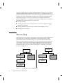
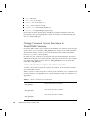
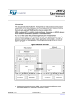
Device Tree
The kernel uses a tree structure to represent various physical machine configurations.
Each node in the tree structure is described by a device-information structure.
Standard device drivers and their devices are associated with leaf nodes. These
drivers are called leaf drivers. Bus drivers are associated with bus nexus nodes and
are called bus nexus drivers. This manual documents writing leaf drivers and one
type of nexus driver, a SCSI host bus adapter (HBA) driver. This manual does not
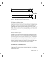
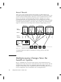
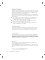
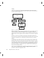
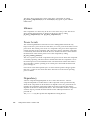
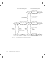
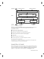
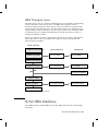
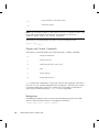
document any other type of bus nexus driver. Figure 1–1 illustrates two possible
device tree configurations.
root node
root node
PCI
bus nexus node
onboard uart
SBus
bus nexus node
leaf node
leaf node
SBus
bus nexus node
xyz device
leaf node
Figure 1–1
4
Possible Device Tree Configurations
Writing Device Drivers ♦ October 1998
onboard uart
xyz device
leaf node
The topmost node in the device tree is called the root node. The tree structure creates
a parent-child relationship between nodes. This parent-child relationship is the key to
architectural independence. When a leaf or bus nexus driver requires a service that is
architecturally dependent in nature, it requests its parent to provide the service.
The intermediate nodes in the tree are generally associated with buses, such as the
SBus, SCSI, and PCI buses. These nodes are called bus nexus nodes and the drivers
associated with them are called bus nexus drivers. Bus nexus drivers encapsulate the
architectural dependencies associated with a particular bus.
This approach enables drivers to function regardless of the architecture of the
machine or the processor. The xyz driver, for example, is source compatible with the
architectural configurations shown in Figure 1–1; it can be binary compatible if the
system uses the same instruction set architecture.
Additionally, in Figure 1–1, the bus nexus driver associated with the PCI-to-SBus
adapter card handles all of the architectural dependencies of the interface. The xyz
driver only needs to determine that it is connected to an SBus.
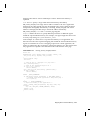
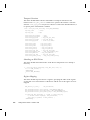
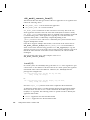
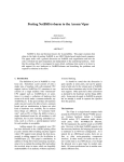
Example Device Tree
In this example, the system builds a tree structure that contains information about
the devices connected to the machine at boot time. The system uses this information
to create a dependency tree with bus nexus nodes and leaf nodes.
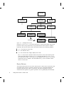
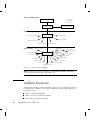
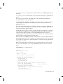
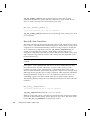
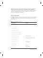
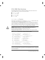
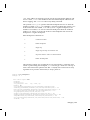
Figure 1–2 illustrates a sample device tree for a frame buffer (SUNW,ffb), a pseudo
bus nexus node, and several PCI devices associated with a PCI bus nexus node.
SunOS Kernel and Device Tree 5
root node
PCI bus
nexus node
pseudo
nexus node
ebus
fdthree
SUNW,CS4231
Leaf Nodes
Figure 1–2
hme
SUNW,ffb
leaf node
glm
se
sd0
sd6
Example Device Tree
In Figure 1–2, the SUNW,ffb leaf node represents a system frame buffer. The pseudo
bus nexus node is the parent node of any pseudo device drivers (drivers without
hardware). The PCI bus nexus node is the parent node for the following children:
4 ebus—the ebus bus nexus node
4 hme—the Ethernet driver
4 glm—the SCSI host bus adapter (HBA) nexus node
The ebus nexus node is both the child of the PCI bus nexus node and the parent
node of the following leaf nodes: fdthree (a floppy disk device), SUNW,CS4231
(an audio device) and se (a serial device). The Ethernet driver (hme) is a leaf node
and therefore has no children. The SCSI HBA node (glm) has a number of disk
devices as leaf nodes.
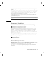
Device Drivers
Associated with each leaf or bus nexus node may be a device driver. Each driver has
associated with it a device operations structure (see dev_ops(9S)) that defines the
operations that the device driver can perform. The device operations structure
contains function pointers for generic operations such as getinfo(9E) and attach(9E).
6
Writing Device Drivers ♦ October 1998
It also contains a pointer to operations specific to bus nexus drivers and a pointer to
operations specific to leaf drivers.
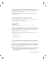
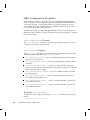
Displaying the Device Tree
The device tree can be displayed in two ways:
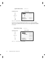
1. The prtconf(1M) command displays all of the device nodes in the device tree.
2. The /devices hierarchy is a representation of the device tree; use ls(1) to view
it.
Note - /devices displays only devices that have drivers configured into the
system. prtconf(1M) shows all device nodes regardless of whether a driver for
the device exists on the system or not.
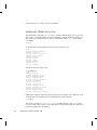
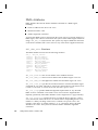
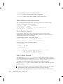
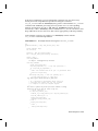
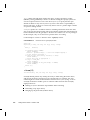
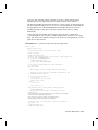
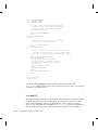
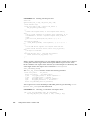
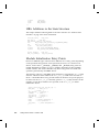
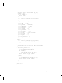
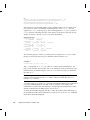
prtconf(1M)
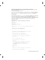
The prtconf(1M) command (excerpted example follows) displays all the devices in
the system:
SUNW,Ultra-1
...
pci, instance #0
ebus, instance #0
auxio (driver not attached)
power (driver not attached)
SUNW,pll (driver not attached)
sc (driver not attached)
se, instance #0
su, instance #0
su, instance #1
ecpp (driver not attached)
fdthree (driver not attached)
eeprom (driver not attached)
flashprom (driver not attached)
SUNW,CS4231 (driver not attached)
network, instance #0
scsi, instance #0
disk (driver not attached)
tape (driver not attached)
sd, instance #0
sd, instance #1 (driver not attached)
sd, instance #2 (driver not attached)
sd, instance #3 (driver not attached)
sd, instance #4 (driver not attached)
sd, instance #5 (driver not attached)
....
pci, instance #1
SUNW,UltraSPARC-II (driver not attached)
SUNW,ffb (driver not attached)
pseudo, instance #0
SunOS Kernel and Device Tree 7
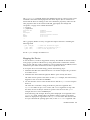
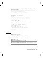
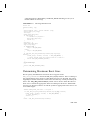
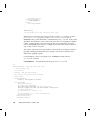
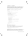
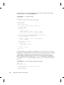
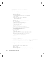
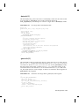
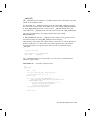
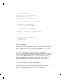
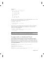
/devices
The /devices hierarchy provides a name space that represents the device tree.
Following is an abbreviated listing of the /devices name space. The sample output
corresponds to the example device tree and prtconf(1M) output shown previously.
/devices
/devices/pseudo
/devices/SUNW,ffb@1e,0:ffb0
/devices/pci@1f,4000/ebus@1
/devices/pci@1f,4000/scsi@3
/devices/pci@1f,4000/scsi@3:devctl
/devices/pci@1f,4000/ebus@1/ecpp@14,3043bc:ecpp0
/devices/pci@1f,4000/ebus@1/se@14,400000:0,hdlc
/devices/pci@1f,4000/ebus@1/se@14,400000:1,hdlc
/devices/pci@1f,4000/ebus@1/se@14,400000:a
/devices/pci@1f,4000/ebus@1/se@14,400000:a,cu
/devices/pci@1f,4000/ebus@1/se@14,400000:b
/devices/pci@1f,4000/ebus@1/se@14,400000:b,cu
/devices/pci@1f,4000/ebus@1/SUNW,CS4231@14,200000:sound,audio
/devices/pci@1f,4000/ebus@1/SUNW,CS4231@14,200000:sound,audioctl
/devices/pci@1f,4000/scsi@3/sd@0,0:a
/devices/pci@1f,4000/scsi@3/sd@0,0:a,raw
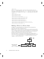
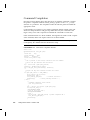
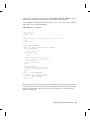
Binding a Driver to a Device Node
In addition to constructing the device tree, the kernel must also determine the
drivers that will be used to manage the devices.
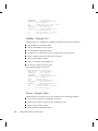
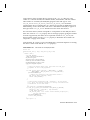
Binding a driver to a device node refers to the process by which the system selects a
driver to manage a particular device. The driver binding name is the name that links
a driver to a unique device node in the device information tree. For each device in
the device tree, the system chooses a driver from a list of drivers.
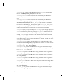
Each device node has a name property associated with it. This property may be
derived either from an external agent such as the PROM during system boot or from
a driver.conf file. In either case, the name property represents the node name
assigned to a device in the device tree.
device node names
(name property)
Figure 1–3
8
SUNW, CS4231
Device Node Names
Writing Device Drivers ♦ October 1998
fdthree
se
A device node may also have a compatible property associated with it. The compatible
property (if it exists) contains an ordered list of one or more possible driver names
for the device.
The system uses both the name and the compatible properties to select a driver for the
device. If the compatible property exists, the system first attempts to match the
contents of the compatible property to a driver on the system. The compatible property
is simply a list of possible driver names from which the system can determine the
specific driver binding name for the device.
Beginning with the first driver name on the compatible property list, the system
attempts to match the driver name to a known driver on the system. It processes
each entry on the list until either a match is found or the end of the list is reached.
If the contents of either the name property or the compatible property match a driver
on the system, then that driver is bound to the device node. If no match is found, no
driver is bound to the device node.
Generic Device Names
Some devices with a compatible property use a generic device name as the value for
the name property. Generic device names describe the function of a device without
actually identifying a specific driver for the device. For example, a SCSI host bus
adapter may have a generic device name of scsi. An Ethernet device may have a
generic device name of ethernet.
The compatible property allows the system to determine alternate driver names (like
glm for scsi HBA device drivers or hme for ethernet device drivers) for devices
with a generic device name.
Devices with generic device names must supply a compatible property.
Note - For a complete description of generic device names, see the IEEE 1275 Open
Firmware Boot Standard.
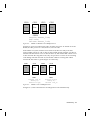
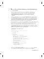
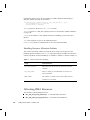
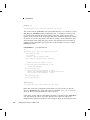
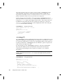
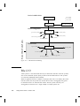
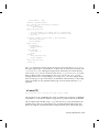
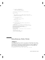
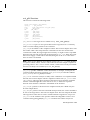
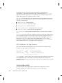
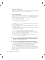
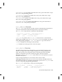
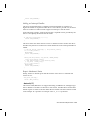
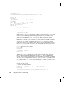
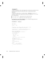
Figure 1–4 and Figure 1–5 show two device nodes: one node uses a specific device
name and the other uses a generic device name.
For the device node with a specific device name, the driver binding name SUNW,ffb
is the same name as the device node name.
SunOS Kernel and Device Tree 9
Specific Device Name
System Driver List
Device Node
esp
isp
cgsix
sd
SUNW,ffb
st
pci
Figure 1–4
(SUNW,ffb)
properties :
name =
SUNW,ffb
node name :
binding name :
SUNW,ffb
SUNW,ffb
Specific Driver Node Binding
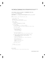
For the device node with the generic device name display, the driver binding
name SUNW,ffb is the first name on the compatible property driver list that matches
a driver on the system driver list. In this case, display is a generic device name for
frame buffers.
Generic Device Name
System Driver List
esp
isp
cgsix
sd
SUNW,ffb
st
pci
Figure 1–5
10
(display)
Device Node
properties :
name =
compatible =
display
node name :
binding name :
display
SUNW,ffb
Generic Driver Node Binding
Writing Device Drivers ♦ October 1998
fast_fb
SUNW,ffb
slow_fb
CHAPTER
2
Hardware Overview
This chapter discusses some general issues about the hardware that the SunOS 5.7
operating system runs on. This includes issues related to the processor, bus
architectures, and memory models supported by the Solaris 7 operating environment,
various device issues, and the PROM used in Sun platforms.
Note - The information presented here is for informational purposes only and may
be of help during driver debugging. However, the Solaris 7 DDI/DKI hides many of
these implementation details from device drivers.
SPARC Processor Issues
This section describes a number of SPARC processor-specific topics including data
alignment, byte ordering, register windows, and availability of floating-point
instructions. For information on x86 processor-specific topics, see “x86 Processor
Issues” on page 13.
SPARC Data Alignment
All quantities must be aligned on their natural boundaries. Using standard C data
types:
4 short integers are aligned on 16-bit boundaries.
4 int integers are aligned on 32-bit boundaries.
11
4 long integers are aligned on either 32-bit boundaries or 64-bit boundaries,
depending on whether the data model of the kernel is 64-bit or 32-bit. For
information on data models, see Appendix F.
4 long long integers are aligned on 64-bit boundaries.
Usually, the compiler handles alignment issues. Driver writers are more likely to
be concerned about alignment as they must use the proper data types to access
their device. Since device registers are commonly accessed through a pointer
reference, drivers must ensure that pointers are properly aligned when accessing
the device. See “Data Access Functions” on page 42 for more information about
accessing device registers.
SPARC Structure Member Alignment
Because of the data alignment restrictions imposed by the SPARC processor, C
structures also have alignment requirements. Structure alignment requirements are
imposed by the most strictly-aligned structure component. For example, a structure
containing only characters has no alignment restrictions, while a structure containing
a long long member must be constructed to guarantee that this member falls on a
64-bit boundary. See “Structure Padding” on page 45 for more information on how
this restriction relates to device drivers.
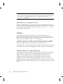
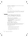
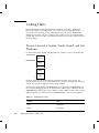
SPARC Byte Ordering
The SPARC processor uses big-endian byte ordering; in other words, the most
significant byte of an integer is stored at the lowest address of the integer.
Byte 0
Byte 1
Byte 2
Byte 3
MSB
LSB
SPARC Register Windows
SPARC processors use register windows. Each register window is comprised of 8 in
registers, 8 local registers, and 8 out registers (which are the in registers of the next
window). There are also 8 global registers. The number of register windows ranges
from 2 to 32, depending on the processor implementation.
Because drivers are normally written in C, the compiler usually hides the fact that
register windows are used. However, it may be necessary to use them when
debugging the driver. See “Debugging Tools” on page 304 for more information on
how register windows are used when debugging.
12
Writing Device Drivers ♦ October 1998
SPARC Floating-Point Operations
Drivers should not perform floating-point operations, as they are not supported in
the kernel.
SPARC Multiply and Divide Instructions
The Version 7 SPARC processors do not have multiply or divide instructions. These
instructions are emulated in software and should be avoided. Because a driver
cannot determine whether it is running on a Version 7, Version 8, or Version 9
processor, intensive integer multiplication and division should be avoided if possible.
Instead, use bitwise left and right shifts to multiply and divide by powers of two.
SPARC Architecture Manual
The SPARC Architecture Manual, Version 9, contains more specific information on
the SPARC CPU.
x86 Processor Issues
This section describes a number of x86 processor-specific topics including data
alignment, byte ordering, and floating-point instructions.
x86 Data Alignment
There are no alignment restrictions on data types. However, extra memory cycles
may be required for the x86 processor to properly handle misaligned data transfers.
x86 Structure Member Alignment
See “Structure Padding” on page 45 for more information on how this relates to
device drivers.
Hardware Overview
13
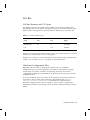
x86 Byte Ordering
The x86 processor uses little-endian byte ordering. The least significant byte of an
integer is stored at the lowest address of the integer.
Byte 0
Byte 1
Byte 2
Byte 3
LSB
MSB
x86 Floating-Point Operations
Drivers should not perform floating-point operations, as they are not supported in
the kernel.
x86 Architecture Manuals
Intel Corporation publishes a number of books on the x86 family of processors:
4 Intel Corporation, 80386 Programmer’s Reference Manual, 1986. ISBN
1-55512-022-9.
4 Intel Corporation, i486 Microprocessor Hardware Reference Manual, 1990. ISBN
1-55512-112-8.
4 Intel Corporation, Pentium Processor User’s Manual - Volume 3: Architecture and
Programming Manual, 1993. ISBN 1-55512-195-0.
Store Buffers
To improve performance, the CPU uses internal store buffers to temporarily store
data. This may affect the synchronization of device I/O operations. Therefore, the
driver needs to take explicit steps to make sure that writes to registers are completed
at the proper time.
For example, when access to device space (such as registers or a frame buffer) is
synchronized by a lock, the driver needs to check that the store to the device space
has actually completed before releasing the lock. Releasing the lock does not
guarantee the flushing of I/O buffers.
To give another example, when acknowledging an interrupt, the driver usually sets
or clears a bit in a device control register. The driver must ensure that the write to
the control register has reached the device before the interrupt handler returns.
Similarly, if the device requires a delay (the driver busy-waits) after writing a
14
Writing Device Drivers ♦ October 1998
command to the control register, the driver must ensure that the write has reached
the device before delaying.
If the device registers can be read without undesirable side effects, verification of a
write can be as simple as reading the register immediately after writing to it. If that
particular register cannot be read without undesirable side effects, another device
register in the same register set can be used.
System Memory Model
The system memory model defines the semantics of memory operations such as load
and store and specifies how the order in which these operations are issued by a
processor is related to the order in which they reach memory. The memory model
applies to both uniprocessors and shared-memory multiprocessors. Two memory
models are supported: total store ordering (TSO) and partial store ordering (PSO).
Total Store Ordering (TSO)
TSO guarantees that the sequence in which store, FLUSH, and atomic load-store
instructions appear in memory for a given processor is identical to the sequence in
which they were issued by the processor.
Both x86 and SPARC processors support TSO.
Partial Store Ordering (PSO)
PSO does not guarantee that the sequence in which store, FLUSH, and atomic
load-store instructions appear in memory for a given processor is identical to the
sequence in which they were issued by the processor. The processor can reorder the
stores so that the sequence of stores in memory is not the same as the sequence of
stores in the CPU.
SPARC processors support PSO; x86 processors do not.
For SPARC processors, conformance between issuing order and memory order is
provided by the system framework using the STBAR instruction: if two of the above
instructions are separated by an STBAR in the issuing order of a processor, or if they
reference the same location, the memory order of the two instructions is the same as
the issuing order. Note that enforcement of strong data ordering in DDI-compliant
drivers is provided by the ddi_regs_map_setup()(9F) interface. Compliant
drivers cannot use the STBAR instruction directly.
Hardware Overview
15
See the SPARC Architecture Manual, Version 9, for more details on the SPARC
memory model.
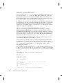
Bus Architectures
This section describes a number of bus-specific topics including device identification,
device addressing, and interrupts.
Device Identification
Device identification is the process of determining which devices are present in the
system.
Self-Identifying Devices
Some devices are self-identifying—the device itself provides information to the
system so that it can identify the device driver that needs to be used. The device
usually provides additional information to the system in the form of name-value
(name=value) pairs that can be retrieved using the property interfaces. See
“Properties” on page 55 for more information on properties.
SBus and PCI local bus devices are examples of self-identifying devices. On SBus, the
information is usually derived from a small Forth program stored in the FCode
PROM on the device. PCI devices provide a configuration space containing device
configuration information. See sbus(4) and pci(4) for more information.
Non-Self-Identifying Devices
Devices that do not provide information to the system to identify themselves are
called non-self-identifying devices. Drivers for these devices must have a probe(9E)
routine that determines whether the device is really present. In addition, information
about the device must be provided in a hardware configuration file (see
driver.conf(4)), so that the system can provide probe(9E) with the information it
needs to contact the device. See probe(9E) for more information.
A VMEbus device is an example of a non-self-identifying device. See vme(4) for
more information.
16
Writing Device Drivers ♦ October 1998
Interrupts
The SunOS system supports polling interrupts and vectored interrupts.The Solaris 7
DDI/DKI interrupt model is the same for both. See “Types of Interrupts” on page 99
for more information about interrupt handling.
Bus Specifics
This section covers addressing and device configuration issues specific to the buses
that the SunOS system supports.
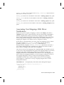
PCI Local Bus
The PCI local bus is a high-performance bus designed for high-speed data transfer.
The PCI bus usually resides on the system board and operates at speeds close to
those of the host processor. The PCI bus is normally used as an interconnect
mechanism between highly integrated peripheral components, peripheral add-on
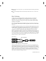
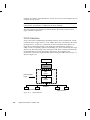
boards, and processor or memory systems. The processor, main memory, and the PCI
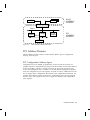
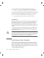
bus itself are connected through a PCI host bridge, as shown in Figure 2–1.
A tree structure of interconnected I/O buses is supported through a series of PCI bus
bridges. Subordinate PCI bus bridges can be extended underneath the PCI host
bridge to allow a single bus system to be expanded into a complex system with
multiple secondary buses. PCI devices can be connected to one of these secondary
buses. In addition, other bus bridges, such as SBus or ISA-bus, can be connected.
Every PCI device has a unique vendor ID and device ID. Multiple devices of the
same kind are further identified by their unique device numbers on the bus where
they reside.
Typical PCI devices include SCSI adapters, graphics and display adapters, host bus
adapters, network controllers, and so on.
Hardware Overview
17
RAM
CPU
PCI Host
Bridge
Bus 0
Graphics
Adapter
Vendor-id = 8006
Device-id = 4a3
Device # = 3
PCI Bus
Vendor-id = 1020
Device-id = 3
Device # = 1
PCI Bus
Bridge
Vendor-id = 8080
Device-id = 520
Device # = 2
LAN
Adapter
Vendor-id = 1001
Device-id = 4b
Device # = 3
Bus 1
SCSI HBA
Figure 2–1
Vendor-id = 1000
Device-id = 4
Device # = 1
Machine Block Diagram
The PCI host bridge provides an interconnect between the processor and peripheral
components. Through the PCI host bridge, the processor can directly access main
memory independent of other PCI bus masters. For example, while the CPU is
fetching data from the cache controller in the host bridge, other PCI devices can also
access the system memory through the host bridge. The advantage of this
architecture lies in its separation of the I/O bus from the processor’s host bus.
The PCI host bridge also provides data access mappings between the CPU and
peripheral I/O devices. It maps every peripheral device to the host address domain
so that the processor can access the device through memory mapped I/O or special I/O
instructions. On the local bus side, the PCI host bridge maps the system memory to
the PCI address domain so that the PCI device can access the host memory as a bus
master. Figure 2–2 shows the two address domains.
18
Writing Device Drivers ♦ October 1998
RAM
HOST
ADDRESS
DOMAIN
LAN
Adapter
PCI
ADDRESS
DOMAIN
CPU
PCI Host Bridge
Bus 0
PCI Bus
Graphics
Bridge
Adapter
Bus 1
SCSI HBA
Figure 2–2
Host and Bus Address Domains
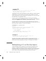
PCI Address Domain
The PCI address domain consists of three distinct address spaces: configuration,
memory, and I/O space.
PCI Configuration Address Space
Configuration space is defined geographically; in other words, the location of a
peripheral device is determined by its physical location within an interconnected tree
of PCI bus bridges. A device is usually located by its bus number and device (slot)
number. Each peripheral device contains a set of well-defined configuration registers
in its PCI configuration space. The registers are used not only to identify devices but
also to supply device configuration information to the configuration framework. For
example, base address registers in the device configuration space must be mapped
before a device can respond to data access. Figure 2–3 illustrates the configuration
space registers.
Hardware Overview
19
I/O
Memory
Configuration
Configuration Registers
Device ID
Vendor ID
Status
Command
Class Code
Base Address 1
Base Address 2
..
Base Address 6
Expansion ROM base
Int
Pin
Figure 2–3
Int
Line
PCI Configuration Address Space
The method for generating configuration cycles is host dependent. In x86 machines,
special I/O ports are used. On other platforms, the PCI configuration space may be
memory-mapped to certain address locations corresponding to the PCI host bridge in
the host address domain. When a device configuration register is accessed by the
processor, the request will be routed to the PCI host bridge. The bridge then
translates the access into proper configuration cycles on the bus.
PCI Configuration Base Address Registers
The PCI configuration space consists of up to six 32-bit base address registers for
each device. These registers provide both size and data type information. System
firmware assigns base addresses in the PCI address domain to these registers.
The firmware identifies the size of each addressable region by writing all 1’s to the
base address register and then reading back the value. The device will return 0’s in
all don’t-care address bits, effectively specifying the size of the address space.
Each addressable region can be either memory or I/O space. The value contained in
bit 0 of the base address register identifies the type. A value of 0 in bit 0 indicates a
memory space and value of 1 indicates an I/O space. Figure 2–4 shows two base
address registers: one for memory; the other for I/O types.
20
Writing Device Drivers ♦ October 1998
4
31
Base Address
3
2 1
Type
0
0
Base Address Register for Memory
space indicator
2
31
Base Address
Resv
0
1
1
Base Address Register for I/O
Figure 2–4
Base Address Registers for Memory and I/O
PCI Memory Address Space
PCI supports both 32-bit and 64-bit addresses for memory space. System firmware
assigns regions of memory space in the PCI address domain to PCI peripherals. The
base address of a region is stored in the base address register of the device’s PCI
configuration space. The size of each region must be a power of two, and the
assigned base address must be aligned on a boundary equal to the size of the region.
Device addresses in memory space are memory-mapped into the host address domain
so that data access to any device can be performed by the processor’s native load or
store instructions.
PCI I/O Address Space
PCI supports 32-bit I/O space. I/O space may be accessed differently on different
platforms. Processors with special I/O instructions, like the Intel processor family,
access the I/O space with in and out instructions. Machines with no special I/O
instructions are usually memory-mapped to the address locations corresponding to
the PCI host bridge in the host address domain. When the processor accesses the
memory-mapped addresses, an I/O request will be sent to the PCI host bridge. It
then translates the addresses into I/O cycles and puts them on the PCI bus.
Memory-mapped I/O is performed by the native load/store instructions of the
processor. For example, reading from or writing to a memory mapped data register
can be done by a load or store instruction to that register’s I/O address.
PCI Hardware Configuration Files
Hardware configuration files should be unnecessary for PCI local bus devices.
However, on some occasions drivers for PCI devices may need to use hardware
configuration files to augment the driver private information. See driver.conf(4) and
pci(4) for further details.
Hardware Overview
21
SBus
Typical SBus systems consist of a motherboard (containing the CPU and SBus
interface logic), a number of SBus devices on the motherboard itself, and a number
of SBus expansion slots. An SBus can also be connected to other types of buses
through an appropriate bus bridge.
The SBus is geographically addressed; each SBus slot exists at a fixed physical
address in the system. An SBus card has a different address depending on which slot
it is plugged into. Moving an SBus device to a new slot causes the system to treat it
as a new device. See “Persistent Instances” on page 84 for more information.
The SBus uses polling interrupts. When an SBus device interrupts, the system only
knows which of several devices might have issued the interrupt. The system
interrupt handler must ask the driver for each device whether it is responsible for
the interrupt.
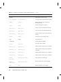
SBus Physical Address Space
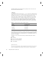
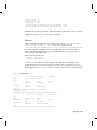
Table 2–1 shows the physical address space layout of the Sun UltraTM 2. A physical
address on the Ultra 2 consists of 41 bits. The 41-bit physical address space is further
broken down into multiple 33-bit address spaces identified by PA(40:33).
TABLE 2–1
22
Device Physical Space in the Ultra 2
PA(40:33)
33-bit Space
Usage
0x0
0x000000000 - 0x07FFFFFFF
2GB Main memory
0x80 – 0xDF
Reserved on Ultra 2
Reserved on Ultra 2
0xE0
Processor 0
Processor 0
0xE1
Processor 1
Processor 1
0xE2 – 0xFD
Reserved on Ultra 2
Reserved on Ultra 2
0xFE
0x000000000 - 0x1FFFFFFFF
UPA Slave (FFB)
0xFF
0x000000000 - 0x0FFFFFFFF
System I/O space
0x100000000 - 0x10FFFFFFF
SBus Slot 0
0x110000000 - 0x11FFFFFFF
SBus Slot 1
Writing Device Drivers ♦ October 1998
TABLE 2–1
PA(40:33)
Device Physical Space in the Ultra 2
(continued)
33-bit Space
Usage
0x120000000 - 0x12FFFFFFF
SBus Slot 2
0x130000000 - 0x13FFFFFFF
SBus Slot 3
0x1D0000000 - 0x1DFFFFFFF
SBus Slot D
0x1E0000000 - 0x1EFFFFFFF
SBus Slot E
0x1F0000000 - 0x1FFFFFFFF
SBus Slot F
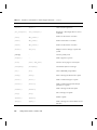
Physical SBus Addresses
The SBus has 32 address bits, as described in the SBus Specification. Table 2–2
describes how the Ultra 2 uses the address bits.
TABLE 2–2
Ultra 2 SBus Address Bits
Bits
Description
0 - 27
These bits are the SBus address lines used by an SBus card to address
the contents of the card.
28 - 31
Used by the CPU to select one of the SBus slots. These bits generate the
SlaveSelect lines.
This addressing scheme yields the Ultra 2 addresses shown in Table 2–1. Other
implementations may use a different number of address bits.
The Ultra 2 has seven SBus slots, four of which are physical. Slots 0 through 3 are
available for SBus cards. Slots 4-12 are reserved. The slots are used in the following
way:
4 Slots 0–3 are physical slots that have DMA-master capability.
4 Slots D, E, and F are not actual physical slots, but refer to the onboard direct
memory access (DMA), SCSI, Ethernet, and audio controllers. For convenience,
these are viewed as being plugged into slots D, E, and F.
Hardware Overview
23
Note - Some SBus slots are slave-only slots, such as slot 3 on the SPARCstation1.
Drivers that require DMA capability should use ddi_slaveonly(9F) to determine if
their device is in a DMA-capable slot. For an example of this function, see
“attach()” on page 87.
SBus Hardware Configuration Files
Hardware configuration files are normally unnecessary for SBus devices. However,
on some occasions drivers for SBus devices may need to use hardware configuration
files to augment the information provided by the SBus card. See driver.conf(4)
and sbus(4) for further details.
VMEbus
The VMEbus supports multiple address spaces. Appropriate entries in the
driver.conf(4) file should be made for the address spaces used by the device For
DMA devices, the address space that the board uses for its DMA transfers must be
known by the driver (this is usually a 32- or 24-bit space).
A VMEbus card has its own address, possibly configurable by jumpers. A VMEbus
card has the same address no matter which slot it is plugged into. Changing the
address of a VME card causes the system to treat it as a new device.
The VMEbus uses vectored interrupts. When a VMEbus device interrupts, the system
can identify which device is interrupting and call the correct device driver directly.
VMEbus Hardware Configuration Files
Most VME devices require hardware configuration files to inform the system that the
device hardware may be present. The configuration file must specify the device
addresses on the VMEbus and any interrupt capabilities that the device has.
Configuration files for VMEbus devices should identify the parent bus driver
implicitly using the class keyword and specifying class “vme.” This removes the
dependency on the name of the particular bus driver involved, since the driver may
be named differently on different platforms. See driver.conf(4) and vme(4) for further
details.
24
Writing Device Drivers ♦ October 1998
ISA Bus
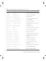
ISA Bus Memory and I/O Space
Two address spaces are provided: memory address space and I/O address space.
Depending on the device, registers may appear in one or both of these address spaces.
Table 2–3 shows the registers for memory and I/O address spaces in the ISA bus.
TABLE 2–3
ISA Bus Address Space
ISA Space
Address
Data Transfer
Physical Address
Name
Size
Size
Range
Main memory
24
16
0x0-0xffffff
I/O
—
8/16
0x0-0xfff
Registers can be mapped in memory address space and used by the driver as normal
memory (see “Memory Space Access” on page 43).
Registers in I/O space are accessed through I/O port numbers using separate kernel
routines. See “I/O Space Access” on page 43 for more information.
Hardware Configuration Files
Beginning with the Solaris 7 operating environment, the use of hardware
configuration files to provide arguments to probe(9E) on x86 platforms is highly
discouraged, since probes can lead to system hangs and resets. Exact device
configuration information is maintained by the booting system and is passed to the
probe(9E) function.
A separate realmode driver may need to be developed for the booting system. See
the Realmode Drivers white paper in the Driver Development Site at http://
www.sun.com/developers/driver for information on realmode drivers.
Hardware configuration files may be needed on some occasions to augment the
information provided by the booting system. See driver.conf(4) and isa(4) for further
details.
Hardware Overview
25
EISA Bus
Memory and I/O Space
Two address spaces are provided: memory address space and I/O address space.
Depending on the device, registers may appear in one or both of these address spaces.
Table 2–4 shows the registers for memory and I/O address spaces in the EISA bus.
TABLE 2–4
EISA Bus Address Space
EISA Space
Address
Data Transfer
Physical Address
Name
Size
Size
Range
Main Memory
32
32
0x0-0xffffffff
I/O
—
8/16/32
0x0-0xffff
Registers can be mapped in memory address space and used by the driver as normal
memory (see “Memory Space Access” on page 43).
Registers in I/O space are accessed through I/O port numbers using separate kernel
routines. See “I/O Space Access” on page 43 for more information.
Hardware Configuration Files
Beginning with the Solaris7 operating envionment, the use of hardware configuration
files to provide arguments to probe(9E) on x86 platforms is highly discouraged, since
probes can lead to system hangs and resets. Exact device configuration information is
maintained by the booting system and is passed to the probe(9E) function.
A separate realmode driver may need to be developed for the booting system. See
the Realmode Drivers white paper in the Driver Development Site at
http://www.sun.com/developers/driver for information on realmode drivers.
Hardware configuration files may be needed on some occasions to augment the
information provided by the booting system. See driver.conf(4) and eisa(4) for further
details.
26
Writing Device Drivers ♦ October 1998
MCA Bus
Memory and I/O Space
Two address spaces are provided: memory address space and I/O address space.
Depending on the device, registers may appear in one or both of these address
spaces.
TABLE 2–5
MCA Address Space
MCA Space
Address
Data Transfer
Physical Address
Name
Size
Size
Range
Main Memory
32
32
0x0-0xffffffff
I/O
—
8/16/32
0x0-0xfff
Registers can be mapped in memory address space and used by the driver as normal
memory (see “Device Memory Mapping” on page 39).
Registers in I/O space are accessed through I/O port numbers using separate kernel
routines. See “I/O Space Access” on page 43) for more information.
Hardware Configuration Files
Hardware configuration files are normally unnecessary for MCA devices. However,
on some occasions drivers for MCA devices may need to use hardware configuration
files to augment the information provided by the MCA card. See driver.conf(4)
and mca(4) for further details.
Device Issues
Timing-Critical Sections
While most driver operations can be performed without synchronization and
protection mechanisms beyond those provided by the locking primitives described in
“Multithreading Additions to the State Structure” on page 72, some devices require
that a sequence of events happen in order without interruption. In conjunction with
the locking primitives, the function ddi_enter_critical(9F) asks the system to
Hardware Overview
27
guarantee, to the best of its ability, that the current thread will neither be pre-empted
nor interrupted. This stays in effect until a closing call to ddi_exit_critical(9F) is
made. See ddi_enter_critical(9F) for details.
Delays
Many chips specify that they can be accessed only at specified intervals. For
example, the Zilog Z8530 SCC has a “write recovery time” of 1.6 microseconds. This
means that a delay must be enforced with drv_usecwait(9F) when writing characters
with an 8530. In some instances, it is unclear what delays are needed; in such cases,
they must be determined empirically.
Internal Sequencing Logic
Devices with internal sequencing logic map multiple internal registers to the same
external address. There are various kinds of internal sequencing logic:
4 The Intel 8251A and the Signetics 2651 alternate the same external register
between two internal mode registers. Writing to the first internal register is
accomplished by writing to the external register. This write, however, has the side
effect of setting up the sequencing logic in the chip so that the next read/write
operation refers to the second internal register.
4 The NEC PD7201 PCC has multiple internal data registers. To write a byte into a
particular register, two steps must be performed. The first step is to write into
register zero the number of the register into which the following byte of data will
go. The data is then written to the specified data register. The sequencing logic
automatically sets up the chip so that the next byte sent will go into data register
zero.
4 The AMD 9513 timer has a data pointer register that points at the data register
into which a data byte will go. When sending a byte to the data register, the
pointer is incremented. The current value of the pointer register cannot be read.
Interrupt Issues
The following are some common interrupt-related issues:
4 A controller interrupt does not necessarily indicate that both the controller and one
of its slave devices are ready. For some controllers, an interrupt may indicate that
either the controller is ready or one of its devices is ready, but not both.
4 Not all devices power up with interrupts disabled and then start interrupting only
when told to do so.
28
Writing Device Drivers ♦ October 1998
4 Some devices do not provide a way to determine that the board has generated an
interrupt.
4 Not all interrupting boards shut off interrupts when told to do so or after a bus
reset.
Byte Ordering
To achieve the goal of multiple platform, multiple instruction set architecture
portability, host bus dependencies were removed from the drivers. The first
dependency issue to be addressed was the endian-ness (or byte ordering) of the
processor. For example, the x86 processor family is little endian while the SPARC
architecture is big endian.
Bus architectures display the same endian-ness types as processors. The PCI local
bus, for example, is little endian, the SBus is big endian, the ISA bus is little endian
and so on.
To maintain portability between processors and buses, DDI-compliant drivers must
be endian neutral. Although drivers could conceivably manage their endian-ness by
runtime checks or by preprocessor directives like #ifdef _LITTLE_ENDIAN or
_BIG_ENDIAN statements in the source code, long-term maintenance would be
troublesome. The Solaris 7 DDI solution hides the endian-ness issues from the
drivers as illustrated in Figure 2–5. In some cases, the DDI framework performs the
byte swapping using a software approach. In other cases, where byte swapping can
be done by hardware (as in memory management unit (MMU) page-level swapping
or by special machine instructions), the DDI framework will take advantage of the
hardware features to improve performance.
Byte Ordering
Data = 0xfea927b0
b0 27 a9 fe
little endian host
SWAP
CPU
fe a9 27 b0
big endian host
Figure 2–5
fe a9 27 b0
big endian device
Byte Ordering Host Bus Dependency
Along with being endian-neutral, portable drivers must also be independent from
data ordering of the processor. Under most circumstances, data must be transferred
in the sequence instructed by the driver. However, sometimes data can be merged,
batched, or reordered to streamline the data transfer, as illustrated in Figure 2–6. For
example, data merging may be applied to accelerate graphics display on frame
buffers. Drivers have the option to advise the DDI framework to use other optimal
data transfer mechanisms during the transfer.
Hardware Overview
29
Data Ordering
ff 00 aa ee
Figure 2–6
ff 00
CPU
aa ee
strict order
ff 00 aa
ee
data merging
00 aa ee
ff
data reordering
Data Ordering Host Bus Dependency
Device Attribute Representations
Device attribute (or device-related) information may be represented with a
name=value pair notation called a property.
For example, a reg property is used to represent device registers and onboard
memory. The reg property is a software abstraction that describes device hardware
registers; its value encodes the device register address location and size. Drivers use
the reg property to access device registers.
As another example, an interrupt property is a software abstraction used to represent
the device interrupt; its value encodes the device-interrupt pin number. For more
information on properties, see “Properties” on page 55.
PROM on SPARC Machines
Some platforms have a PROM monitor that provides support for debugging a device
without an operating system. This section describes how to use the PROM on SPARC
machines to map device registers so that they can be accessed. Usually, the device
can be exercised enough with PROM commands to determine if the device is
working correctly.
The PROM has several purposes; it serves to:
4 Bring the machine up from power on, or from a hard reset PROM reset
command.
4 Provide an interactive tool for examining and setting memory, device registers,
and memory mappings.
4 Boot the SunOS system or the kernel debugger kadb(1M).
Simply powering up the computer and attempting to use its PROM to examine
device registers will likely fail. While the device may be correctly installed, those
mappings are SunOS specific and do not become active until SunOS is booted.
Upon power up, the PROM maps only essential system devices, such as the
keyboard.
30
Writing Device Drivers ♦ October 1998
Open Boot PROM 3.x
For complete documentation on the Open Boot PROM, see the Open Boot PROM
Toolkit User’s Guide and monitor(1M). The examples in this section refer to a Sun-4u
architecture; other architectures may require different commands to perform actions.
Note - The Open Boot PROM is currently used on Sun machines with an SBus or
UPA/PCI. The Open Boot PROM uses an “ok” prompt. On older machines, it may
be necessary to type ‘n’ to get the “ok” prompt.
If the PROM is in secure mode (the security-mode parameter is not set to none) the
PROM password may be required (set in the security-password parameter).
The printenv command displays all parameters and their values.
Help
Help is available with the help command.
History
EMACS-style command-line history is available. Use Control-N (next) and Control-P
(previous) to traverse the history list.
Forth Commands
The Open Boot PROM uses the Forth programming language. This is a stack-based
language; arguments must be pushed on the stack before running the desired
command (called a word), and the result is left on the stack.
To place a number on the stack, type its value.
ok 57
ok 68
To add the two top values on the stack, use the + operator.
ok +
The result remains on the stack. The stack is shown with the .s word.
ok .s
bf
The default base is hexadecimal. The hex and decimal words can be used to switch
bases.
ok decimal
ok .s
Hardware Overview
31
191
See the Forth User’s Guide for more information.
Walking the PROMs Device Tree
The SunOS-like commands pwd, cd, and ls walk the PROM device tree to get to the
device. The cd command must be used to establish a position in the tree before pwd
will work. This example is from an Ultra-1 workstation with a cgsix frame buffer
on an SBus.
ok cd /
To see the devices attached to the current node in the tree, use ls.
ok ls
f006a064
f00598b0
f00592dc
f004eec8
f004e8e8
f002ca28
f002c9b8
f002c880
f002c814
f002c7a4
SUNW,UltraSPARC@0,0
sbus@1f,0
counter-timer@1f,3c00
virtual-memory
memory@0,0
aliases
options
openprom
chosen
packages
The full node name can be used:
ok cd sbus@1f,0
ok ls
f006a4e4 cgsix@2,0
f0068194 SUNW,bpp@e,c800000
f0065370 ledma@e,8400010
f006120c espdma@e,8400000
f005a448 SUNW,pll@f,1304000
f005a394 sc@f,1300000
f005a24c zs@f,1000000
f005a174 zs@f,1100000
f005a0c0 eeprom@f,1200000
f0059f8c SUNW,fdtwo@f,1400000
f0059ec4 flashprom@f,0
f0059e34 auxio@f,1900000
f0059d28 SUNW,CS4231@d,c000000
Rather than using the full node name in the previous example, you could have used
an abbreviation. The abbreviated command line entry looks like this:
ok cd sbus
The name is actually device@slot,offset (for SBus devices). The cgsix device
is in slot 2 and starts at offset 0. If an SBus device is displayed in this tree, the device
has been recognized by the PROM.
32
Writing Device Drivers ♦ October 1998
The.properties command displays the PROM properties of a device. These can be
examined to determine which properties the device exports (this is useful later to
ensure that the driver is looking for the correct hardware properties). These are the
same properties that can be retrieved with ddi_getprop(9F). See sbus(4) and
“Properties” on page 55 for related information.
ok cd cgsix
ok .properties
character-set
intr
interrupts
reg
dblbuf
vmsize
...
ISO8859-1
00000005 00000000
00000005
00000002 00000000 01000000
00 00 00 00
00 00 00 01
The reg property defines an array of register description structures containing the
following fields:
u_int bustype;
u_int addr;
u_int size;
/* cookie for related bus type*/
/* address of reg relative to bus */
/* size of this register set */
For the cgsix example, the address is 0.
Mapping the Device
To test the device, it must be mapped into memory. The PROM can then be used to
verify proper operation of the device by using data-transfer commands to transfer
bytes, words, and long words. If the device can be operated from the PROM, even in
a limited way, the driver should also be able to operate the device.
To set up the device for initial testing, perform the following steps:
1. Determine the SBus slot number the device is in. In this example, the cgsix device
is located in slot 2.
2. Determine the offset within the physical address space used by the device.
The offset used is specific to the device. In the cgsix example, the video memory
happens to start at an offset of 0x800000.
3. Use the select-dev word to select the sbus device and the map-in word to map the
device in.
The select-dev word takes a string of the device path as its argument. The
map-in word takes an offset, a slot number, and a size as arguments to map. Like
the offset, the size of the byte transfer is specific to the device. In the cgsix
example, the size is set to 0x100000 bytes.
In the following code example, the sbus path is displayed as an argument to the
select-dev word, and the offset, slot number, and size values for the frame
buffer are displayed as arguments to the map-in word. Notice that there should
be a space between the opening quote and / in the select-dev argument. The
Hardware Overview
33
virtual address to use remains on top of the stack. The stack is shown using the
.s word. It can be assigned a name with the constant operation.
ok ‘‘/sbus@1f,0’’ select-dev
ok 800000 2 100000 map-in
ok .s
ffe98000
ok constant fb
Reading and Writing
The PROM provides a variety of 8-bit, 16-bit, and 32-bit operations. In general, a c
(character) prefix indicates an 8-bit (one byte) operation; a w (word) prefix indicates a
16-bit (two byte) operation; and an L (longword) prefix indicates a 32-bit (four byte)
operation.
A suffix of ! is used to indicate a write operation. The write operation takes the first
two items off the stack; the first item is the address, and the second item is the value.
ok 55 ffe98000 c!
A suffix of @ is used to indicate a read operation. The read operation takes one
argument (the address) off the stack.
ok ffe98000 c@
ok .s
55
A suffix of ? is used to display the value, without affecting the stack.
ok ffe98000 c?
55
Be careful when trying to query the device. If the mappings are not set up correctly,
trying to read or write could cause errors. There are special words provided to
handle these cases. cprobe, wprobe, and lprobe, for example, read from the given
address but return zero if the location does not respond, or nonzero if it does.
ok fffa4000 c@
Data Access Error
ok fffa4000 cprobe
ok .s
0
ok ffe98000 cprobe
ok .s
0 ffffffffffffffff
A region of memory can be shown with the dump word. This takes an address and a
length, and displays the contents of the memory region in bytes.
In the following example, the fill word is used to fill video memory with a
pattern. fill takes the address, the number of bytes to fill, and the byte to use
34
Writing Device Drivers ♦ October 1998
(there is also a wfill and an Lfill for words and longwords). This causes the cgsix
to display simple patterns based on the byte passed.
ok
ok
ok
ok
ok
ok
ok
ok
ok
‘‘ /sbus’’ select-dev
800000 2 100000 map-in
constant fb
fb 10000 ff fill
fb 20000 0 fill
fb 18000 55 fill
fb 15000 3 fill
fb 10000 5 fill
fb 5000 f9 fill
Interrupts
Certain machine-specific interrupt levels are ignored when the Open Boot PROM
controls the machine.
Hardware Overview
35
36
Writing Device Drivers ♦ October 1998
CHAPTER
3
Overview of SunOS Device Drivers
This chapter gives an overview of SunOS device drivers. It discusses what a device
driver is and the types of device drivers that Solaris 7 supports. It also provides a
general discussion of the routines that device drivers must implement and points out
compiler-related issues.
What Is a Device Driver?
A device driver is a kernel module responsible for managing low-level I/O operations
for a particular hardware device. Device drivers can also be software-only, emulating
a device that exists only in software, such as a RAM disk or a pseudo-terminal. Such
device drivers are called pseudo device drivers and cannot perform functions
requiring hardware (such as DMA).
A device driver contains all the device-specific code necessary to communicate with
a device and provides a standard I/O interface to the rest of the system. This
interface protects the kernel from device specifics just as the system call interface
protects application programs from platform specifics. Application programs and the
rest of the kernel need little (if any) device-specific code to address the device. In this
way, device drivers make the system more portable and easier to maintain.
Types of Device Drivers
There are several kinds of device drivers, each handling a different kind of I/O.
Block device drivers manage devices with physically addressable storage media, such
37
as disks. All other devices are considered character devices. Two types of character
device drivers are standard character device drivers and STREAMS device drivers.
Block Device Drivers
Devices that support a file system are known as block devices. Drivers written for
these devices are known as block device drivers. Block device drivers take a file
system request (in the form of a buf(9S) structure) and issue the I/O operations to
the disk to transfer the specified block. The main interface to the file system is the
strategy(9E) routine. See Chapter 10, for more information.
Block device drivers can also provide a character driver interface that allows utility
programs to bypass the file system and access the device directly. This device access
is commonly referred to as the raw interface to a block device.
Standard Character Device Drivers
Character device drivers normally perform I/O in a byte stream. They can also
provide additional interfaces not present in block drivers, such as I/O control
(ioctl(9E)) commands, memory mapping, and device polling. See Chapter 9, for
more information.
Byte-Stream I/O
The main task of any device driver is to perform I/O, and many character device
drivers do what is called byte-stream or character I/O. The driver transfers data to and
from the device without using a specific device address. This is in contrast to block
device drivers, where part of the file system request identifies a specific location on
the device.
The read(9E) and write(9E) entry points handle byte-stream I/O for standard
character drivers. See “I/O Request Handling” on page 157 for more information.
I/O Control
Many devices have characteristics and behavior that can be configured or tuned. The
ioctl(2) system call and the ioctl(9E) driver entry point provide a mechanism for
application programs to change and determine the status of a driver’s configurable
characteristics. For example, the baud rate of a serial communications port is usually
configurable in this way.
The I/O control interface is open ended, enabling device drivers to define special
commands for the device. The definition of the commands is entirely determined by
38
Writing Device Drivers ♦ October 1998
the driver and is restricted only by the requirements of the application programs
using the device and the device itself.
Certain classes of devices such as frame buffers or disks must support standard sets
of I/O control requests. These standard I/O control interfaces are documented in the
Solaris 2.7 Reference Manual. For example, fbio(7I) documents the I/O controls that
frame buffers must support, and dkio(7I) documents standard disk I/O controls. See
“Miscellaneous I/O Control ” on page 169 for more information on I/O control.
Note - This manual does not cover I/O control commands.
Device Memory Mapping
For certain devices, such as frame buffers, it is more efficient for application programs
to have direct access to device memory. Applications can map device memory into
their address spaces using the mmap(2) system call. To support memory mapping,
device drivers implement segmap(9E) and devmap(9E) entry points. For information
on devmap(9E), see Chapter 11. For information on segmap(9E), see Chapter 9.
Drivers that define an devmap(9E) entry point usually do not define read(9E) and
write(9E) entry points, as application programs perform I/O directly to the devices
after calling mmap(2).
Device Polling
The poll(2) system call enables application programs to monitor or poll a set of file
descriptors for certain conditions or events. poll(2) can be used to find out whether
data are available to be read from the file descriptors or whether data may be written
to the file descriptors without delay. Drivers referred to by these file descriptors must
provide support for the poll(2) system call by implementing a chpoll(9E) entry
point.
Drivers for communication devices such as serial ports should support polling, as
they are used by applications that require synchronous notification of changes in
read and write status. Many communications devices, however, are better
implemented as STREAMS drivers.
STREAMS Drivers
STREAMS is a separate programming model for writing a character driver. Devices
that receive data asynchronously (such as terminal and network devices) are suited
to a STREAMS implementation. STREAMS device drivers must provide the loading
and autoconfiguration support described in Chapter 5. See the Streams Programming
Guide for additional information on how to write STREAMS drivers.
Overview of SunOS Device Drivers
39
Bus Address Spaces
Three types of bus address space are memory space, I/O space, and configuration
space. The device driver usually accesses memory space through memory mapping
and I/O space through I/O ports. The configuration address space is accessed
primarily during system initialization.
The preferred method depends on the device; it is generally not software
configurable. For example, SBus and VMEbus devices do not provide I/O ports or
configuration space, but some PCI devices may provide all three.
The data format of the host may also have different endian characteristics than the
data format of the device. If this is the case, data transferred between the host and
the device needs to be byte swapped to conform to the data format requirements of
the destination location. Other devices may have the same endian characteristics as
their host. In this case, no byte swapping is required. The DDI framework performs
any required byte swapping on behalf of the driver. The driver simply needs to
specify the endianness of the device to the framework.
Address Mapping Setup
Before a driver can access a device’s bus address, the bus address spaces must be set
up using ddi_regs_map_setup(9F). The driver can then access the device by
passing the data access handle returned from ddi_regs_map_setup(9F) to one of
the ddi_get8(9F) or ddi_put8(9F) family of routines.
One of the arguments required by ddi_regs_map_setup(9F) is a pointer to a
device access attributes structure, ddi_device_acc_attr(9S). The
ddi_device_acc_attr(9S) structure describes the data access characteristics and
requirements of the device. The ddi_device_acc_attr(9S) structure contains the
following members:
ushort_t
uchar_t
uchar_t
devacc_attr_version;
devacc_attr_endian_flags;
devacc_attr_dataorder;
devacc_attr_version member identifies the version number of this structure.
The current version number is DDI_DEVICE_ATTR_V0.
devacc_attr_endian_flags member describes the endian characteristics of the
device. If DDI_NEVERSWAP_ACC is set, data access with no byte swapping is
indicated. This flag should be set when no byte swapping is required. For example, if
a device does byte-stream I/O, no byte swapping is required. If
DDI_STRUCTURE_BE_ACC is set, the device data format is big endian. If
DDI_STRUCTURE_LE_ACC is set, the device data format is little endian.
40
Writing Device Drivers ♦ October 1998
The framework will do any required byte swapping on behalf of the driver based on
the flags indicated in devacc_attr_endian_flags and the host’s data format
endian characteristics.
devacc_attr_dataorder describes the order in which the CPU will reference
data. Certain hosts may load or store data in certain orders to pipeline performance.
The data ordering may be programmed to execute in one of the following ways:
4 Strong data ordering – If DDI_STRICTORDER_ACC is set, the CPU must issue the
references in order, as specified by the programmer. This is the default behavior.
4 Reordering – If DDI_UNORDERED_OK_ACC is set, the CPU may reorder the data
reference. This includes all kinds of reordering (for example, a load followed by a
store may be replaced by a store followed by a load).
4 Data merging – If DDI_MERGING_OK_ACC is set, the CPU may merge individual
stores to consecutive locations. For example, the CPU may turn two consecutive
byte stores into one halfword store. It may also batch individual loads. For
example, the CPU may turn two consecutive byte loads into one halfword load.
DDI_MERGING_OK_ACC also implies reordering.
4 Cache loading – If DDI_LOADCACHING_OK_ACC is set, the CPU may cache the
data it fetches and reuse it until another store occurs. The default behavior is to
fetch new data on every load. DDI_LOADCACHING_OK_ACC also implies
merging and reordering.
4 Cache storing – If DDI_STORECACHING_OK_ACC is set, the CPU may keep the
data in the cache and push it to the device (perhaps with other data) at a later
time. The default behavior is to push the data right away.
DDI_STORECACHING_OK_ACC also implies load caching, merging, and
reordering.
Note - The restriction to the hosts diminishes while moving from strong data
ordering to cache storing in terms of data accesses by the driver.
The values assigned to devacc_attr_dataorder are advisory, not mandatory. For
example, data can be ordered without being merged or cached, even though a driver
requests unordered, merged, and cached together.
A driver for a big-endian device that requires strict data ordering during data
accesses would encode the ddi_device_acc_attr structure as follows:
static ddi_device_acc_attr_t access_attr = {
DDI_DEVICE_ATTR_V0, /* version number */
DDI_STRUCTURE_BE_ACC, /* big endian */
DDI_STRICTORDER_ACC /* strict ordering */
}
The system will use the information stored in the ddi_device_acc_attr structure
and other system-specific information to encode an opaque data handle as one of the
returned parameters from ddi_map_regs_setup(9F). The returned data handle is
used as a parameter to the data access routines (such as ddi_put8(9F) or
Overview of SunOS Device Drivers
41
ddi_get8(9F)) during subsequent accesses to the mapped registers. The driver must
never attempt to interpret the contents of the data handle.
If successful, ddi_regs_map_setup(9F) also returns a kernel virtual address that is
mapped to the bus address base. The address base may be used as a base reference
address in deriving the effective address of other registers by adding the appropriate
offset.
Note - Drivers should not directly dereference the returned address. A driver must
access the device through one of the data access functions.
Data Access Functions
Data access functions allow drivers to transfer data to and from devices without
directly referencing the hardware registers. The driver can transfer data to the device
or receive data from the device using the ddi_put8(9F) or the ddi_get8(9F)
families of routines. The ddi_put8(9F) routines allow a driver to write data to the
device in quantities of 8 bits (ddi_put8(9F)), 16 bits (ddi_put16(9F)), 32 bits
(ddi_put32(9F)), and 64 bits (ddi_put64(9F)). The ddi_get8(9F) routines exist for
reading from a device. Multiple values may be written or read by using the
ddi_rep_put8(9F) or ddi_rep_get8(9F) family of routines respectively. See
Appendix C for more information on data access functions.
Note - These routines may be applied to any address base returned from
ddi_regs_map_setup(9F) regardless of the address space the register resides in
(such as memory, I/O, or configuration space).
Code Example 3–1 illustrates the use of ddi_regs_map_setup(9F) and
ddi_put8(9F) to access device registers.
CODE EXAMPLE 3–1
Accessing Device Registers
static ddi_device_acc_attr_t access_attr = {
DDI_DEVICE_ATTR_V0, /*version number */
DDI_STRUCTURE_BE_ACC, /* big endian */
DDI_STRICTORDER_ACC /*strict ordering */
};
caddr_t reg_addr;
ddi_acc_handle_t data_access_handle;
ddi_regs_map_setup(..., ®_addr, ..., &access_attr,
&data_access_handle);
When ddi_regs_map_setup(9F) returns, reg_addr contains the address base and
data_access_handle contains the opaque data handle to be used in subsequent
42
Writing Device Drivers ♦ October 1998
data accesses. The driver may now access the mapped registers. The following
example writes one byte to the first mapped location.
ddi_put8(data_access_handle, (uint8_t *)reg_addr, 0x10);
Similarly, the driver could have used ddi_get8(9F) to read data from the device
registers.
Memory Space Access
In memory-mapped access, device registers appear in memory address space. The
driver must call ddi_regs_map_setup(9F) to set up the mapping. The driver can
then access the device registers using one of the ddi_put8(9F) or ddi_get8(9F)
family of routines.
To access memory space, the driver can use the ddi_mem_put8(9F) and
ddi_mem_get8(9F) family of routines. These functions may be more efficient on
some platforms. Use of these routines, however, may limit the ability of the driver to
remain portable across different bus versions of the device.
I/O Space Access
In I/O space access, the device registers appear in I/O space. Each addressable
element of the I/O address is called an I/O port. Device registers are accessed
through I/O port numbers. These port numbers can refer to 8, 16, or 32-bit registers.
The driver must call ddi_regs_map_setup(9F) to set up the mapping, and it can
then access the I/O port using one of the ddi_put8(9F) or ddi_get8(9F) family of
routines.
The driver can also access I/O space using the ddi_io_put8(9F) and
ddi_io_get8(9F) family of routines. These functions may be more efficient on some
platforms. Use of these routines, however, may limit the ability of the driver to
remain portable across different bus versions of the device.
Configuration Space Access
Configuration space is used primarily during device initialization. It determines the
location and size of register sets and memory buffers located on the device. The
driver can access configuration space using the ddi_regs_map_setup(9F) and the
ddi_put(9F or ddi_get(9F) functions as described previously.
Overview of SunOS Device Drivers
43
Note - For PCI local bus devices, an alternative set of routines exists. To get access to
the configuration address space, the driver can use pci_config_setup(9F) in place
of ddi_regs_map_setup(9F). The pci_config_get8(9F) and
pci_config_put8(9F) family of routines may be used in place of the generic
routines ddi_get8(9F) and ddi_put8(9F). These functions provide equivalent
configuration space access as defined in the PCI bus binding for the IEEE 1275
specifications for FCode drivers. However, use of these routines may limit the ability
of the driver to remain portable across different bus versions of the device.
Example Device Registers
Most of the examples in this manual use a fictitious device that has an 8-bit
command and status register (csr), followed by an 8-bit data register. The command
and status register is so called because writes to it go to an internal command
register, and reads from it are directed to an internal status register.
The command register looks like this:
Enable Interrupts
Clear Interrupt
Start Transfer
The status register looks like this:
Interrupt Pending
Interrupts Enabled
Device Busy
Error Occurred
Transfer Complete
Many drivers provide macros for the various bits in their registers to make the code
more readable. The examples in this manual use the following names for the bits in
the command register:
#define ENABLE_INTERRUPTS
#define CLEAR_INTERRUPT
#define START_TRANSFER
0x10
0x08
0x04
For the bits in the status register, the examples use following macros:
#define INTERRUPTS_ENABLED
#define INTERRUPTING
#define DEVICE_BUSY
44
Writing Device Drivers ♦ October 1998
0x10
0x08
0x04
#define
#define
DEVICE_ERROR
TRANSFER_COMPLETE
0x02
0x01
Device Register Structure
Using pointer accesses to communicate with the device results in unreadable code.
For example, the code that reads the data register when a transfer has been
completed might look like this:
uint8_t data;
uint8_t status;
/* get status */
status = ddi_get8(data_access_handle, (uint8_t *)reg_addr);
if (status & TRANSFER_COMPLETE) {
data = ddi_get8(data_access_handle,
(uint8_t *)reg_addr + 1); /* read data */
}
To make the code more readable, it is common to define a structure that matches the
layout of the device registers. In this case, the structure could look like this:
struct device_reg {
uint8_t csr;
uint8_t data;
};
The driver then maps the registers into memory and refers to them through a pointer
to the structure:
struct device_reg *regp;
...
ddi_regs_map_setup(..., (caddr_t *)®p, ... ,
&access_attributes, &data_access_handle);
...
The code that reads the data register upon a completed transfer now looks like this:
uint8_t data;
uint8_t status;
/* get status */
status = ddi_get8(data_access_handle, ®p->csr);
if (status & TRANSFER_COMPLETE) {
/* read data */
data = ddi_get8(data_access_handle, ®p->data);
}
Structure Padding
A device that has a 1-byte command and status register followed by a 4-byte data
register might lead to the following structure layout:
struct device_reg {
uint8_t
csr;
uint32 _t data;
};
Overview of SunOS Device Drivers
45
This structure is not correct, because the compiler places padding between the two
fields. For example, the SPARC processor requires each type to be on its natural
boundary, which is 1-byte alignment for the csr field, but 4-byte alignment for the
data field. This results in three unused bytes between the two fields. When the
driver accesses a data register, it will be three bytes off. Consequently, this layout
should not be used.
Finding Padding
The ANSI C offsetof(3C) macro may be used in a test program to determine the
offset of each element in the structure. Knowing the offset and the size of each
element, the location and size of any padding can be determined.
CODE EXAMPLE 3–2
Structure Padding
#include <sys/types.h>
#include <stdio.h>
#include <stddef.h>
struct device_reg {
uint8_t
csr;
uint32_t
data;
};
int main(void)
{
printf("The offset of csr is %d, its size is %d.\n",
offsetof(struct device_reg, csr), sizeof (uint8_t));
printf("The offset of data is %d, its size is %d.\n",
offsetof(struct device_reg, data), sizeof (uint32_t));
return (0);
}
Here is a sample compilation with Sun WorkShopTM Compiler C version 4.2 and a
subsequent run of the program:
test% cc -Xa c.c
test% a.out
The offset of csr is 0, its size is 1.
The offset of data is 4, its size is 4.
Be aware that padding is dependent not only on the processor but also on the
compiler.
46
Writing Device Drivers ♦ October 1998
Driver Interfaces
The kernel expects device drivers to provide certain routines that must perform
certain operations; these routines are called entry points. This is similar to the
requirement that application programs have a start( ) entry point or that C
applications have the more familiar main() routine.
Entry Points
Each device driver defines a standard set of functions called entry points, which are
defined in the Solaris 2.7 Reference Manual. Drivers for different types of devices
have different sets of entry points according to the kinds of operations the devices
perform. A driver for a memory-mapped character-oriented device, for example,
supports a devmap(9E) entry point, while a block driver does not.
Some operations are common to all drivers, such as the functions that are required
for module loading (_init(9E), _info(9E), and _fini(9E)), and the required
autoconfiguration entry points attach(9E) and getinfo(9E). Drivers may also
support the optional autoconfiguration entry points for probe(9E) and detach(9E).
Most drivers have open(9E) and close(9E) entry points to control access to their
devices.
Traditionally, all driver function and variable names have some prefix added to
them. Usually, this is the name of the driver, such as xxopen( ) for the open(9E)
routine of driver xx. In subsequent examples, xx is used as the driver prefix.
Note - In the SunOS 5.7 system, only the loadable module routines must be visible
outside the driver object module. Other routines can have the storage class static.
Loadable Module Routines
int _init(void);
int _info(struct modinfo *modinfop);
int _fini(void);
All drivers must implement the _init(9E), _fini(9E) and _info(9E) entry points
to load, unload and report information about the driver module. The driver is
single-threaded when the kernel calls _init(9E). No other thread will enter a driver
routine until mod_install(9F) returns success.
The driver should allocate and initialize any global resources in _init(9E) before
calling mod_install(9F) and release global resources in _fini(9E) after
mod_remove(9F) returns success.
Overview of SunOS Device Drivers
47
Note - Drivers must use these names, and they must not be declared static, unlike
the other entry points where the names and storage classes are determined by the
driver.
Autoconfiguration Entry Points
static int xxprobe(dev_info_t *dip);
static int xxattach(dev_info_t *dip, ddi_attach_cmd_t cmd);
static int xxdetach(dev_info_t *dip, ddi_detach_cmd_t cmd);
static int xxgetinfo(dev_info_t *dip,ddi_info_cmd_t infocmd,
void *arg, void **result);
Any per-device resources should be allocated in attach(9E) and released in
detach(9E). No resources global to the driver should be allocated in attach(9E).
For information on autoconfiguration entry points, see Chapter 5.
Block Driver Entry Points
int xxopen(dev_t *devp, int flag, int otyp, cred_t *credp);
int xxclose(dev_t dev, int flag, int otyp, cred_t *credp);
int xxstrategy(struct buf *bp);
int xxprint(dev_t dev, char *str);
int xxdump(dev_t dev, caddr_t addr, daddr_t blkno, int nblk);
int xxprop_op(dev_t dev, dev_info_t *dip, ddi_prop_op_t prop_op,
int mod_flags, char *name, caddr_t valuep,
int *length);
For information on block driver entry points, see Chapter 10.
Character Driver Entry Points
int xxopen(dev_t *devp, int flag, int otyp, cred_t *credp);
int xxclose(dev_t dev, int flag, int otyp, cred_t *credp);
int xxread(dev_t dev, struct uio *uiop, cred_t *credp);
int xxwrite(dev_t dev, struct uio *uiop, cred_t *credp);
int xxioctl(dev_t dev, int cmd, intptr_t arg, int mode,
cred_t *credp, int *rvalp);
int xxdevmap(dev_t dev, devmap_cookie_t dhp, offset_t off,
size_t len, size_t *maplen, uint_t model);
int xxmmap(dev_t dev, off_t off, int prot);
int xxsegmap(dev_t dev, off_t off, struct as *asp,
caddr_t *addrp, off_t len, unsigned int prot,
unsigned int maxprot, unsigned int flags,
cred_t *credp);
int xxchpoll(dev_t dev, short events, int anyyet,
short *reventsp, struct pollhead **phpp);
int xxprop_op(dev_t dev, dev_info_t *dip,
ddi_prop_op_t prop_op, int mod_flags,
char *name, caddr_t valuep, int *length);
48
Writing Device Drivers ♦ October 1998
int xxaread(dev_t dev, struct aio_req *aio, cred_t *credp);
int xxawrite(dev_t dev, struct aio_req *aio, cred_t *credp);
For information on character driver entry points, see Chapter 9.
Power Management Entry Point
int xxpower(dev_info_t *dip, int component, int level);
Drivers for hardware devices that provide Power Management functionality may
support the optional power(9E) entry point. See Chapter 8for details about this entry
point.
Driver Structure Overview
Figure 3–1 shows data structures and routines that may define the structure of a
character or block device driver. Such drivers typically include a device loadable
driver section, device configuration section, and device access section.
Overview of SunOS Device Drivers
49
Device loadable driver
_init(9E)
_info(9E)
_fini(9E)
modlinkage(9S)
mod_driverops
modldrv(9S)
Device configuration
dev_ops(9S)
getinfo(9E)
probe(9E)
power(9E)
identify(9E)
attach(9E)
Device access
detach(9E)
dump(9E)
chpoll(9E)
open(9E)
cb_ops(9S)
segmap(9E)
mmap(9E)
close(9E)
print(9E)
prop_op(9E)
read(9E)
aread(9E)
write(9E)
ioctl(9E)
devmap(9E)
strategy(9E)
awrite(9E)
Figure 3–1
Device Driver Roadmap
Note - The first two sections in Figure 3-1 are discussed in Chapter 5; the third
section is discussed in Chapter 9 and Chapter 10.
Callback Functions
Some routines provide a callback mechanism. This is a way to schedule a function to
be called when a condition is met. Typical conditions for which callback functions
are set up include:
4 When a transfer has completed
4 When a resource might become available
4 When a time-out period has expired
50
Writing Device Drivers ♦ October 1998
Transfer completion callbacks perform the tasks usually done in an interrupt service
routine.
In some sense, callback functions are similar to entry points. The functions that allow
callbacks expect the callback function to perform certain tasks. In the case of DMA
routines, a callback function must return a value indicating whether the callback
function needs to be rescheduled in case of a failure.
Callback functions execute as a separate interrupt thread and must handle all the
usual multithreading issues.
Note - A driver must cancel all scheduled callback functions before detaching a
device.
Interrupt Handling
The Solaris 7 DDI/DKI addresses these aspects of device interrupt handling:
4 Registering device interrupts with the system
4 Removing device interrupts from the system
Interrupt information is contained in a property called interrupts (or intr on x86
platforms, see isa(4)), which is either provided by the PROM of a self-identifying
device, in a hardware configuration file, or by the booting system on the x86
platform. See sbus(4), vme(4), pci(4), eisa(4), isa(4), mca(4), and “Properties” on
page 55 for more information.
Because the internal implementation of interrupts is an architectural detail, special
interrupt cookies are used to enable drivers to perform interrupt-related tasks. The
types of cookies for interrupts are:
4 Device-interrupt cookies
4 Block-interrupt cookies
Device-Interrupt Cookies
Defined as type ddi_idevice_cookie_t, this cookie is a data structure containing
information used by a driver to program the interrupt-request level (or the
equivalent) for a programmable device. See ddi_add_intr(9F),
ddi_idevice_cookie(9S), and “Registering Interrupts” on page 101 for more
information.
Overview of SunOS Device Drivers
51
Block-Interrupt Cookies
Defined as type ddi_iblock_cookie_t this cookie is used by a driver to initialize
the mutual exclusion locks it uses to protect data. This cookie should not be
interpreted by the driver in any way. For more information on
ddi_get_iblock_cookie(9F), see “Interrupt Block Cookies” on page 98.
Driver Context
The driver context determines which kernel routines the driver is permitted to call.
For example, in kernel context the driver must not call copyin(9F). There are four
contexts in which driver code executes:
4 User context – A driver entry point has user context if it was directly invoked
because of a user thread. For example, the read(9E) entry point of the driver,
invoked by a read(2) system call, has user context.
4 Kernel context – A driver function has kernel context if it was invoked by some
other part of the kernel. In a block device driver, the strategy(9E) entry point
may be called by the pageout daemon to write pages to the device. Because the
page daemon has no relation to the current user thread, strategy(9E) has kernel
context in this case.
4 Interrupt context – Interrupt context is a more restrictive form of kernel context.
Driver interrupt routines operate in interrupt context and have an interrupt level
associated with them. See Chapter 6 for more information.
4 High-level interrupt context – High-level interrupt context is a more restricted form
of interrupt context. If ddi_intr_hilevel(9F) indicates that an interrupt is high
level, the driver interrupt handler will run in high-level interrupt context. See
“Handling High-Level Interrupts” on page 104 for more information.
The manual pages in section 9F document the allowable contexts for each function.
Printing Messages
Device drivers do not usually print messages. Instead, the driver entry points should
return error codes so that the application can determine how to handle the error. If
the driver really needs to print a message, it can use cmn_err(9F) to do so. This is
similar to the C function printf(3S), but only prints to the console, to the message
buffer displayed by dmesg(1M), or both.
void cmn_err(int level, char *format, ...);
52
Writing Device Drivers ♦ October 1998
format is similar to the printf(3S) format string, with the addition of the format
%b, which prints bit fields. level indicates which label will be printed, as shown in
Table 3–1.
TABLE 3–1
cmn_err() Messages
Level
Message
CE_NOTE
NOTICE: format\n
CE_WARN
WARNING:format\n
CE_CONT
format
CE_PANIC
panic: format\n
CE_PANIC has the side effect of crashing the system. This level should only be used
if the system is in such an unstable state that to continue would cause more
problems. It can also be used to get a system core dump when debugging.
The first character of the format string is treated specially. See cmn_err(9F) for more
details.
Dynamic Memory Allocation
Device drivers must be prepared to simultaneously handle all attached devices that
they claim to drive. There should be no driver limit on the number of devices that
the driver handles, and all per-device information must be dynamically allocated.
void *kmem_alloc(size_t size, int flag);
The standard kernel memory allocation routine is kmem_alloc(9F). It is similar to
the C library routine malloc(3C), with the addition of the flag argument. The flag
argument can be either KM_SLEEP or KM_NOSLEEP, indicating whether the caller is
willing to block if the requested size is not available. If KM_NOSLEEP is set, and
memory is not available, kmem_alloc(9F) returns NULL.
kmem_zalloc(9F) is similar to kmem_alloc(9F), but also clears the contents of the
allocated memory.
Overview of SunOS Device Drivers
53
Note - Kernel memory is a limited resource, not pageable, and competes with user
applications and the rest of the kernel for physical memory. Drivers that allocate a
large amount of kernel memory may cause system performance to degrade.
void kmem_free(void *cp, size_t size);
Memory allocated by kmem_alloc(9F) or by kmem_zalloc(9F) is returned to the
system with kmem_free(9F). This is similar to the C library routine free(3C), with
the addition of the size argument. Drivers must keep track of the size of each object
they allocate in order to call kmem_free(9F) later.
Software State Management
Software State Structure
For each device that the driver handles, the driver must keep some state information.
At a minimum, this consists of a pointer to the dev_info node for the device
(required by getinfo(9E)). The driver can define a structure that contains all the
information needed about a single device:
struct xxstate {
dev_info_t
*dip;
};
This structure will grow as the device driver evolves. Additional useful fields might
be a pointer to each of the device’s mapped registers, or flags such as busy or
suspended. The initial state structure the examples in this book use is given in Code
Example 3–3.
CODE EXAMPLE 3–3
Initial State Structure
struct xxstate {
dev_info_t
*dip;
struct device_reg
*regp;
int
xx_busy;
struct xx_saved_device_state
};
device_state;
Subsequent chapters in this manual may require that new fields be added to the state
structure. Each chapter will list any additions.
54
Writing Device Drivers ♦ October 1998
Software State Management Routines
To assist device driver writers in allocating state structures, the Solaris 7 DDI/DKI
provides a set of memory management routines called the software state management
routines (also known as the soft state routines). These routines dynamically allocate,
retrieve, and destroy memory items of a specified size, and hide all the details of list
management in a multithreaded kernel. An item number is used to identify the
desired memory item; this number can be (and usually is) the instance number
assigned by the system.
The driver must provide a state pointer, which is used by the soft state system to
create the list of memory items:
static void *statep;
Routines are provided to:
4 Initialize the provided state pointer – ddi_soft_state_init(9F)
4 Allocate space for a certain item – ddi_soft_state_zalloc(9F)
4 Retrieve a pointer to the indicated item – ddi_get_soft_state(9F)
4 Free the memory item – ddi_soft_state_free(9F)
4 Finish using the state pointer – ddi_soft_state_fini(9F)
When the module is loaded, the driver calls ddi_soft_state_init(9F) to
initialize the driver state pointer, passing a hint indicating how many items to
pre-allocate. If more items are needed, the driver will allocate them as necessary. The
driver must call ddi_soft_state_fini(9F) when the driver is unloaded.
To allocate an instance of the soft state structure, the driver calls
ddi_soft_state_zalloc(9F). Once the item is allocated, the driver calls
ddi_get_soft_state(9F) to retrieve the pointer to the allocated structure. This is
usually done when the device is attached. When the device is detached, the driver
calls ddi_soft_state_free(9F) to free the memory.
See “Loadable Driver Interface” on page 81 for an example use of these routines.
Properties
Properties define arbitrary characteristics of the device or device driver. Properties
may be defined by the FCode of a self-identifying device, by a hardware
configuration file (see driver.conf(4)), or by the driver itself using the
ddi_prop_update(9F) family of routines.
A property is a name-value pair. The name is a string that identifies the property
with an associated value. Examples of properties are the height and width of a frame
Overview of SunOS Device Drivers
55
buffer, the number of blocks in a partition of a block device, or the name of a device.
The value of a property can be one of five types:
4 A byte array that has an arbitrary length and whose value is a series of bytes
4 An integer property whose value is an integer
4 An integer array property whose value is an array of integers
4 A string property whose value is a NULL-terminated string
4 A string array property whose value is a list of NULL-terminated strings
A property that has no value is known as a Boolean property. It is considered to be
true if it exists and false if it doesn’t exist.
Note - Strictly speaking, DDI/DKI software property names are not restricted in any
way; however, there are certain recommended uses. As defined in IEEE 1275-1994
(the Standard for Boot Firmware), a property “is a human readable text string
consisting of one to thirty-one printable characters. Property names shall not contain
upper case characters or the characters "/", "\", ":", "[", "]" and "@". Property names
beginning with the character "+" are reserved for use by future revisions of IEEE
1275-1994.” By convention, underscores are not used in property names; use a
hyphen (-) instead. Also by convention, property names ending with the question
mark character (auto-boot?) contain values that are strings, typically true or false.
A driver can request a property from its parent, which in turn might ask its parent.
The driver can control whether the request can go higher than its parent.
For example, the “esp” driver maintains an integer property for each target called
target x-sync-speed, where “x” is the target number. The prtconf(1M)
command in its verbose mode displays driver properties. The following example
shows a partial listing for the “esp” driver.
test% prtconf -v
...
esp, instance #0
Driver software properties:
name <target2-sync-speed> length <4>
value <0x00000fa0>.
...
Table 3–2 provides information on the property interfaces.
56
Writing Device Drivers ♦ October 1998
TABLE 3–2
Property Interface Uses
Family
ddi_prop_lookup
Property Interfaces
Description
ddi_prop_exists(9F)
Looks up property and returns success
if one exists. Returns failure if one does
not exist.
ddi_prop_get_int(9F)
Looks up and returns an integer
property.
ddi_prop_lookup_int_array(9F)
Looks up and returns an integer array
property.
ddi_prop_lookup_string(9F)
Looks up and returns a string property.
Looks up and returns a string array
ddi_prop_lookup_string_array(9F)
property.
Looks up and returns a byte array
ddi_prop_lookup_byte_array(9F) property.
ddi_prop_update
ddi_prop_update_int(9F)
ddi_prop_update_int_array(9F)
ddi_prop_update_string(9F)
Updates an integer property.
Updates an integer array property.
Updates a string property.
Updates an string array property.
ddi_prop_update_string_array(9F)
ddi_prop_update_byte_array(9F)
Updates a byte array property.
Overview of SunOS Device Drivers
57
TABLE 3–2
Property Interface Uses
Family
(continued)
Property Interfaces
ddi_prop_remove
ddi_prop_remove(9F)
ddi_prop_remove_all(9F)
Description
Removes a property.
Removes all properties associated with
a device.
prop_op(9E)
The prop_op(9E) entry point reports the values of device properties to the system.
In many cases, the ddi_prop_op(9F) routine may be used as the driver’s
prop_op(9E) entry point in the cb_ops(9S) structure. ddi_prop_op(9F) performs
all of the required processing and is sufficient for drivers that do not need to perform
any special processing when handling a device property request.
However, there are cases when it is necessary for the driver to provide a
prop_op(9E) entry point. For example, if a driver maintains a property whose value
changes frequently, updating the property with ddi_prop_update(9F) each time it
changes may not be efficient. Instead, the driver can maintain a local copy of the
property in a C variable. The driver updates the C variable when the value of the
property changes and does not call one of the ddi_prop_update(9F) routines. In
this case, the prop_op(9E) entry point would need to intercept requests for this
property and call one of the ddi_prop_update(9F) routines to update the value of
the property before passing the request to ddi_prop_op(9F) to process the property
request. See Code Example 3–4.
Here is the prop_op(9E) prototype:
int xxprop_op(dev_t dev, dev_info_t *dip,
ddi_prop_op_t prop_op, int flags, char *name,
caddr_t valuep, int *lengthp);
Code Example 3–4 shows a simple implementation of the prop_op(9E) routine. This
routine intercepts property requests and then uses the existing software property
routines to update property values. For a complete description of all the parameters
to (9E), see the manual page.
In Code Example 3–4, prop_op(9E) intercepts requests for the temperature
property. The driver updates a variable in the state structure whenever the property
changes but only updates the property when a request is made. It then uses the
system routine ddi_prop_op(9F) to process the property request. If the property
request is not specific to a device, the driver does not intercept the request. This is
58
Writing Device Drivers ♦ October 1998
indicated when the value of the dev parameter is equal to DDI_DEV_T_ANY (the
wildcard device number).
This example adds the following field to the state structure. See “Software State
Structure” on page 54 for more information.
int
temperature; /* current device temperature */
CODE EXAMPLE 3–4
prop_op(9E) Routine
static int
xxprop_op(dev_t dev, dev_info_t *dip, ddi_prop_op_t prop_op,
int flags, char *name, caddr_t valuep, int *lengthp)
{
minor_t instance;
struct xxstate *xsp;
if (dev != DDI_DEV_T_ANY) {
return (ddi_prop_op(dev, dip, prop_op, flags, name,
valuep, lengthp));
}
instance = getminor(dev);
xsp = ddi_get_soft_state(statep, instance);
if (xsp == NULL)
return (DDI_PROP_NOTFOUND);
if (strcmp(name, "temperature") == 0) {
ddi_prop_update_int(dev, dip, name, temperature);
}
/* other cases */
}
Driver Layout
Driver code is usually divided into the following files:
4 Headers (.h files)
4 Source files (.c files)
4 Optional configuration files (driver.conf file)
Note - These files represent a typical driver layout. They are not absolutely required
for a driver, as only the final object module matters to the system.
Overview of SunOS Device Drivers
59
Header Files
Header files define data structures specific to the device (such as a structure
representing the device registers), data structures defined by the driver for
maintaining state information, defined constants (such as those representing the bits
of the device registers), and macros (such as those defining the static mapping
between the minor device number and the instance number).
Some of this information, such as the state structure, may only be needed by the
device driver. This information should go in private headers. These header files are
included only by the device driver itself.
Any information that an application might require, such as the I/O control
commands, should be in public header files. These are included by the driver and any
applications that need information about the device.
There is no standard for naming private and public files. One possible convention is
to name the private header file xximpl.h and the public header file xxio.h. See
Appendix E, for more information.
Source Files
A.c file for a device driver contains the data declarations and the code for the entry
points of the driver. It contains the #include statements the driver needs, declares
extern references, declares local data, sets up the cb_ops and dev_ops structures,
declares and initializes the module configuration section, makes any other necessary
declarations, and defines the driver entry points. See Appendix E, for more
information.
Configuration Files
See driver.conf(4), sbus(4), pci(4). isa(4), and vme(4).
64-Bit-Safe Device Drivers
The Solaris system can run in 64-bit mode on appropriate hardware and provides a
64-bit kernel with a 64-bit address space for applications. To update a device driver
to be 64-bit ready, driver writers need to understand the 32-bit and 64-bit C data type
models, know how to use the system derived types and the fundamental C data
types, and understand specific driver issues, such as how to enable a 64-bit driver
and a 32-bit application to share data structures.
60
Writing Device Drivers ♦ October 1998
For details on making a device driver ready for a 64-bit environment, see Appendix
F.
C Language and Compiler Modes
The Sun WorkShopTM Compiler C version 4.2 provides ANSI C compilers for the
Solaris environment. It supports several compilation modes, a number of useful
keywords, and function prototypes.
Compiler Modes
Note the following compiler modes.
-Xa (ANSI C Mode)
This mode accepts ANSI C and Sun C compatibility extensions. In case of a conflict
between ANSI and Sun C, the compiler issues a warning and uses ANSI C
interpretations. This is the default mode.
-Xt (Transition Mode)
This mode accepts ANSI C and Sun C compatibility extensions. In case of a conflict
between ANSI and Sun C, a warning is issued and Sun C semantics are used.
Function Prototypes
Function prototypes specify the following information to the compiler:
4 The type returned by the function
4 The number of the arguments to the function
4 The type of each argument
CODE EXAMPLE 3–5
Function Prototypes
static int
xxgetinfo(dev_info_t *dip, ddi_info_cmd_t cmd, void *arg,
void **result)
{
/* definition */
}
Overview of SunOS Device Drivers
61
static int
xxopen(dev_t *devp, int flag, int otyp, cred_t *credp)
{
/* definition */
}
This allows the compiler to do more type checking and also to promote the types of
the parameters to the type expected by the function. For example, if the compiler
knows that a function takes a pointer, casting NULL to that pointer type is no longer
necessary. Prototypes are provided for all Solaris 7 DDI/DKI functions, provided the
driver includes the proper header file (documented in the manual page for the
function).
Keywords
ANSI C provides the following driver-related keywords.
const
The const keyword can be used to define constants instead of using #define:
const int
count=5;
However, it is most useful when combined with function prototypes. Routines that
should not be modifying parameters can define the parameters as constants, and the
compiler will then give errors if the parameter is modified. Because C passes
parameters by value, most parameters don’t need to be declared as constants. If the
parameter is a pointer, though, it can be declared to point to a constant object:
int strlen(const char *s)
{
...
}
Any attempt to change the string by strlen() is an error, and the compiler will
catch the error.
volatile
The correct use of volatile is necessary to prevent elusive bugs. It instructs the
compiler to use exact semantics for the declared objects—in particular, to not
optimize away or reorder accesses to the object. There are two instances where
device drivers must use the volatile qualifier:
1. When data refers to an external hardware device register (memory that has side
effects other than just storage). Note, however, that if the DDI data access
functions are used to access device registers, it is not necessary to use volatile.
62
Writing Device Drivers ♦ October 1998
2. When data refers to global memory that is accessible by more than one thread, is
not protected by locks, and therefore is relying on the sequencing of memory
accesses
In general, drivers should not qualify a variable as volatile if it is merely
accessible by more than one thread and protected from conflicting access by
synchronization routines.
The following example uses volatile. A busy flag is used to prevent a thread
from continuing while the device is busy and the flag is not protected by a lock:
while (busy) {
/* do something else */
}
The testing thread will continue when another thread turns off the busy flag:
busy = 0;
However, since busy is accessed frequently in the testing thread, the compiler
may optimize the test by placing the value of busy in a register, then test the
contents of the register without reading the value of busy in memory before
every test. The testing thread would never see busy change and the other thread
would only change the value of busy in memory, resulting in deadlock. Declaring
the busy flag as volatile forces its value to be read before each test.
Note - It would probably be preferable to use a condition variable mutex, discussed
under “Condition Variables” on page 70 rather than the busy flag in this example.
It is also recommended that the volatile qualifier be used in such a way as to
avoid the risk of accidental omission. For example, this code
struct device_reg {
volatile uint8_t csr;
volatile uint8_t data;
};
struct device_reg *regp;
is recommended over:
struct device_reg {
uint8_t csr;
uint8_t data;
};
volatile struct device_reg *regp;
Although the two examples are functionally equivalent, the second one requires
the writer to ensure that volatile is used in every declaration of type struct
device_reg. The first example results in the data being treated as volatile in all
declarations and is therefore preferred. Note as mentioned above, that the use of
the DDI data access functions to access device registers makes it unnecessary to
qualify variables as volatile.
Overview of SunOS Device Drivers
63
64
Writing Device Drivers ♦ October 1998
CHAPTER
4
Multithreading
This chapter describes the locking primitives and thread synchronization
mechanisms of the SunOS multithreaded kernel.
Threads
A thread of control, or thread, is a sequence of instructions executed within a program.
A thread can share data and code with other threads and can run concurrently with
other threads. There are two kinds of threads: user threads and kernel threads. See
Multithreaded Programming Guide for more information on threads.
User Threads
Each process in the SunOS operating system has an address space that contains one
or more lightweight processes (LWPs), each of which in turn runs one or more user
threads. Figure 4–1 shows the relationship between threads, LWPs, and processes. An
LWP schedules its user threads and runs one user thread at a time, though multiple
LWPs may run concurrently. User threads are handled in user space.
The LWP is the interface between user threads and the kernel. The LWP can be
thought of as a virtual CPU that schedules user thread execution. When a user
thread issues a system call, the LWP running the thread calls into the kernel and
remains bound to the thread at least until the system call is complete. When an LWP
is running in the kernel, executing a system call on behalf of a user thread, it runs
one kernel thread. Each LWP is therefore associated with exactly one kernel thread.
65
Kernel Threads
There are two types of kernel threads: those bound to an LWP and those not
associated with an LWP. Threads not associated with LWPs are system threads, such
as those created to handle hardware interrupts. For those threads bound to an LWP,
there is one and only one kernel thread per LWP. On a multiprocessor system,
several kernel threads can run simultaneously. Even on uniprocessors, running
kernel threads can be preempted at any time to run other threads. Drivers are mainly
concerned with kernel threads as most device driver routines run as kernel threads.
Figure 4–1 illustrates the relationship between threads and lightweight processes.
Process 1
Process 2
Process 3
Process 4
User
Threads
Kernel
Kernel
Threads
CPU
Threads
LWP
CPU
CPU
Hardware
Figure 4–1
CPU
CPU
CPU
Threads and Lightweight Processes
A multithreaded kernel requires consideration of locking primitives and thread
synchronization.
Multiprocessing Changes Since the
SunOS 4.1 System
Here is a simplified view of how the earlier releases of the SunOS kernel ran on
multiprocessors. Only one processor could run kernel code at any one time, and this
was enforced by using a master lock around the entire kernel. When a processor
needed to execute kernel code, it acquired the master lock, blocking other processors
from accessing kernel code. It released the lock on exiting the kernel.
66
Writing Device Drivers ♦ October 1998
CPU0
CPU1
CPU2
CPU3
User
User
User
User
Kernel
Kernel
Kernel
Kernel
CPU 1
Acquire master_lock;
Run code;
Release master_lock;
Figure 4–2
SunOS 4.1 Kernels on a Multiprocessor
In Figure 4–2 CPU1 executes kernel code. All other processors are locked out of the
kernel; the other processors could, however, run user code.
In the SunOS 5.7 system, instead of one master lock, there are many locks that
protect smaller regions of code or data. In the example shown in Figure 4–3, there is
a kernel lock that controls access to data structure A, and another that controls access
to data structure B. Using these locks, only one processor at a time can be executing
code dealing with data structure A, but another could be accessing data within
structure B. This allows a greater degree of concurrency.
CPU0
CPU1
CPU2
CPU3
User
User
User
User
Kernel
Kernel
Kernel
Kernel
CPU 1
CPU 3
Acquire lock_A;
Acquire lock_B;
Modify A;
Modify B;
Release lock_A;
Release lock_B;
Figure 4–3 SunOS 5.7 on a Multiprocessor
In Figure 4–3, CPU1 and CPU3 are executing kernel code simultaneously.
Multithreading
67
Locking Primitives
In traditional UNIX systems, any section of kernel code runs until it explicitly gives
up the processor by calling sleep( ) or is interrupted by hardware. This is not true
in SunOS 5.7! A kernel thread can be preempted at any time to run another thread.
Because all kernel threads share kernel address space, and often need to read and
modify the same data, the kernel provides a number of locking primitives to prevent
threads from corrupting shared data. These mechanisms include mutual exclusion
locks, readers/writer locks, and semaphores.
Storage Classes of Driver Data
The storage class of data is a guide to whether the driver might need to take explicit
steps to control access to the data. There are three types of data storage classes:
4 Automatic (stack) data – Because every thread has a private stack, drivers never
need to lock automatic variables.
4 Global and static data – Global and static data can be shared by any number of
threads in the driver; the driver might need to lock this type of data at times.
4 Kernel heap data – Any number of threads in the driver might share kernel heap
data, such as data allocated by kmem_alloc(9F). If this data is shared, the driver
might need to protect it at times.
Mutual-Exclusion Locks
A mutual-exclusion lock, or mutex, is usually associated with a set of data and
regulates access to that data. Mutexes provide a way to allow only one thread at a
time access to that data.
TABLE 4–1
68
Mutex Routines
Name
Description
mutex_init(9F)
Initializes a mutex.
mutex_destroy(9F)
Releases any associated storage.
mutex_enter(9F)
Acquires a mutex.
Writing Device Drivers ♦ October 1998
TABLE 4–1
Mutex Routines
(continued)
Name
Description
mutex_tryenter(9F)
Acquires a mutex if available; but does not block.
mutex_exit(9F)
Releases a mutex.
mutex_owned(9F)
Test sif the mutex is held by the current thread. To be
used in ASSERT(9F) only.
Setting Up Mutexes
Device drivers usually allocate a mutex for each driver data structure. The mutex is
typically a field in the structure and is of type kmutex_t. mutex_init(9F) is called to
prepare the mutex for use. This is usually done at attach(9E) time for per-device
mutexes and _init(9E) time for global driver mutexes.
For example,
struct xxstate *xsp;
...
mutex_init(&xsp->mu, ‘‘xx mutex’’, MUTEX_DRIVER, NULL);
...
For a more complete example of mutex initialization see Chapter 5.
The driver must destroy the mutex with mutex_destroy(9F) before being unloaded.
This is usually done at detach(9E) time for per-device mutexes and _fini(9E) time for
global driver mutexes.
Using Mutexes
Every section of the driver code that needs to read or write the shared data structure
must do the following:
4 Acquire the mutex.
4 Access the data.
4 Release the mutex.
For example, to protect access to the busy flag in the state structure:
...
mutex_enter(&xsp->mu);
xsp->busy = 0;
mutex_exit(&xsp->mu);
....
Multithreading
69
The scope of a mutex—the data it protects—is entirely up to the programmer. A
mutex protects some particular data structure because the programmer chooses to do so
and uses it accordingly. A mutex protects a data structure only if every code path
that accesses the data structure does so while holding the mutex. For additional
guidelines on using mutexes see Appendix G.
Readers/Writer Locks
A readers/writer lock regulates access to a set of data. The readers/writer lock is so
called because many threads can hold the lock simultaneously for reading, but only
one thread can hold it for writing.
Most device drivers do not use readers/writer locks. These locks are slower than
mutexes and provide a performance gain only when protecting data that is not
frequently written but is commonly read by many concurrent threads. In this case,
contention for a mutex could become a bottleneck, so using a readers/writer lock
might be more efficient. See rwlock(9F) for more information.
Semaphores
Counting semaphores are available as an alternative primitive for managing threads
within device drivers. See semaphore(9F) for more information.
Thread Synchronization
In addition to protecting shared data, drivers often need to synchronize execution
among multiple threads.
Condition Variables
Condition variables are a standard form of thread synchronization. They are
designed to be used with mutexes. The associated mutex is used to ensure that a
condition can be checked atomically, and that the thread can block on the associated
condition variable without missing either a change to the condition or a signal that
the condition has changed. Condition variables must be initialized by calling
cv_init(9F) and must be destroyed by calling cv_destroy(9F).
70
Writing Device Drivers ♦ October 1998
Note - Condition variable routines are approximately equivalent to the routines
sleep( ) and wakeup() used in SunOS 4.1.
Table 4–2 lists the condvar(9F) interfaces. The four wait routines – cv_wait(9F),
cv_timedwait(9F), cv_wait_sig(9F), and cv_timedwait_sig(9F) – take a
pointer to a mutex as an argument.
TABLE 4–2
Condition Variable Routines
Name
Description
cv_init(9F)
Initializes a condition variable.
cv_destroy(9F)
Destroys a condition variable.
cv_wait(9F)
Waits for condition.
cv_timedwait(9F)
Waits for condition or timeout.
cv_wait_sig(9F)
Waits for condition or return zero on receipt of a signal.
cv_timedwait_sig(9F)
Waits for condition or timeout or signal.
cv_signal(9F)
Signals one thread waiting on the condition variable.
cv_broadcast(9F)
Signals all threads waiting on the condition variable.
Initializing Condition Variables
Declare a condition variable (type kcondvar_t) for each condition. Usually, this is
done in the driver’s soft-state structure. Use cv_init(9F) to initialize each one.
Similar to mutexes, condition variables are usually initialized at attach(9E) time. For
example:
...
cv_init(&xsp->cv, NULL, CV_DRIVER, NULL);
...
For a more complete example of condition variable initialization see Chapter 5.
Multithreading
71
Multithreading Additions to the State Structure
This section adds the following fields to the state structure. See “Software State
Structure” on page 54 for more information.
int
busy;
kmutex_t
kcondvar_t
/* device busy flag */
mu; /* mutex to protect state structure */
cv; /* threads wait for access here */
Using Condition Variables
To use condition variables, follow these steps in the code path waiting for the
condition:
1. Acquire the mutex guarding the condition.
2. Test the condition.
3. If the test results do not allow the thread to continue, use cv_wait(9F) to block
the current thread on the condition. cv_wait(9F) releases the mutex before
blocking. Upon return from cv_wait(9F) (which will reacquire the mutex before
returning), repeat the test.
4. Once the test allows the thread to continue, set the condition to its new value. For
example, set a device flag to busy.
5. Release the mutex.
Follow these steps in the code path signaling the condition:
1. Acquire the mutex guarding the condition.
2. Set the condition.
3. Signal the blocked thread with cv_signal(9F).
4. Release the mutex.
Code Example 4–1 uses a busy flag, and mutex and condition variables to force the
read(9E) routine to wait until the device is no longer busy before starting a transfer.
CODE EXAMPLE 4–1
Using Mutexes and Condition Variables
static int
xxread(dev_t dev, struct uio *uiop, cred_t *credp)
{
struct xxstate *xsp;
...
mutex_enter(&xsp->mu);
while (xsp->busy)
cv_wait(&xsp->cv, &xsp->mu);
xsp->busy = 1;
mutex_exit(&xsp->mu);
perform the data access
}
static u_int
xxintr(caddr_t arg);
{
struct xxstate *xsp = (struct xxstate *)arg;
72
Writing Device Drivers ♦ October 1998
mutex_enter(&xsp->mu);
xsp->busy = 0;
cv_broadcast(&xsp->cv);
mutex_exit(&xsp->mu);
}
In Code Example 4–1, xxintr( )( )always calls cv_broadcast(9F), even if there are
no threads waiting on the condition. This extra call can be avoided by using a want
flag in the state structure, as shown in Code Example 4–2. Before a thread blocks on
the condition variable (such as because the device is busy), it sets the want flag,
indicating that it wants to be signaled when the condition occurs. When the
condition occurs (the device finishes the transfer), the call to cv_broadcast(9F) is
made only if the want flag is set.
CODE EXAMPLE 4–2
Using a want Flag
static int
xxread(dev_t dev, struct uio *uiop, cred_t *credp)
{
struct xxstate *xsp;
...
mutex_enter(&xsp->mu);
while (xsp->busy) {
xsp->want = 1;
cv_wait(&xsp->cv, &xsp->mu);
}
xsp->busy = 1;
mutex_exit(&xsp->mu);
perform error recovery
}
static u_int
xxintr(caddr_t arg);
{
struct xxstate *xsp = (struct xxstate *)arg;
mutex_enter(&xsp->mu);
xsp->busy = 0;
if (xsp->want) {
xsp->want = 0;
cv_broadcast(&xsp->cv);
}
mutex_exit(&xsp->mu);
}
cv_timedwait(9F)
If a thread blocks on a condition with cv_wait(9F), and that condition does not occur,
it may wait forever. One way to prevent this is to establish a callback with
timeout(9F). This callback sets a flag indicating that the condition did not occur
normally, and then unblocks the thread. The notified thread then notices that the
condition did not occur and can return an error (such as device broken).
A better solution is to use cv_timedwait(9F). An absolute wait time is passed to
cv_timedwait(9F), which returns -1 if the time is reached and the event has not
Multithreading
73
occurred. It returns nonzero otherwise. This saves a lot of work setting up separate
timeout(9F) routines and avoids having threads get stuck in the driver.
cv_timedwait(9F) requires an absolute wait time expressed in clock ticks since the
system was last rebooted. This can be determined by retrieving the current value
with ddi_get_lbolt(9F). The driver usually has a maximum number of seconds or
microseconds to wait, so this value is converted to clock ticks with drv_usectohz(9F)
and added to the value from ddi_get_lbolt(9F).
Code Example 4–3 shows how to use cv_timedwait(9F) to wait up to five seconds to
access the device before returning EIO to the caller.
CODE EXAMPLE 4–3
Using cv_timedwait(9F)
clock_t
cur_ticks, to;
mutex_enter(&xsp->mu);
while (xsp->busy) {
cur_ticks = ddi_get_lbolt();
to = cur_ticks + drv_usectohz(5000000); /* 5 seconds from now */
if (cv_timedwait(&xsp->cv, &xsp->mu, to) == -1) {
/*
* The timeout time ’to’ was reached without the
* condition being signalled.
*/
tidy up and exit
mutex_exit(&xsp->mu);
return (EIO);
}
}
xsp->busy = 1;
mutex_exit(&xsp->mu);
cv_wait_sig()
There is always the possibility that either the driver accidentally waits for a
condition that will never occur (as described in “ cv_timedwait(9F)” on page 73)
or that the condition will not happen for a long time. In either case, the user may
want to abort the thread by sending it a signal. Whether the signal causes the driver
to wake up depends upon the driver.
cv_wait_sig(9F) allows a signal to unblock the thread. This allows the user to break
out of potentially long waits by sending a signal to the thread with kill(1) or by
typing the interrupt character. cv_wait_sig(9F) returns zero if it is returning because
of a signal, or nonzero if the condition occurred.
Code Example 4–4 shows how to use cv_wait_sig(9F) to allow a signal to unblock
the thread.
CODE EXAMPLE 4–4
Using cv_wait_sig(9F)
mutex_enter(&xsp->mu);
while (xsp->busy) {
if (cv_wait_sig(&xsp->cv, &xsp->mu) == 0) {
74
Writing Device Drivers ♦ October 1998
/* Signalled while waiting for the condition. */
tidy up and exit
mutex_exit(&xsp->mu);
return (EINTR);
}
}
xsp->busy = 1;
mutex_exit(&xsp->mu);
cv_timedwait_sig()
cv_timedwait_sig(9F) is similar to cv_timedwait(9F) and cv_wait_sig(9F),
except that it returns -1 without the condition being signaled after a timeout has
been reached, or 0 if a signal (for example, kill(2)) is sent to the thread.
For both cv_timedwait(9F) and cv_timedwait_sig(9F), time is measured in
absolute clock ticks since the last system reboot.
Choosing a Locking Scheme
The locking scheme for most device drivers should be kept straightforward. Using
additional locks may allow more concurrency but increase overhead. Using fewer
locks is less time consuming but allows less concurrency. Generally, use one mutex
per data structure, a condition variable for each event or condition the driver must
wait for, and a mutex for each major set of data global to the driver. Avoid holding
mutexes for long periods of time.
To look at lock usage, use lockstat(1M). lockstat(1M) monitors all kernel lock
events, gathers frequency and timing data about the events, and displays the data.
For more information on locking schemes, see Appendix G. Also see the
Multithreaded Programming Guide for more details on multithreading operations.
Multithreading
75
76
Writing Device Drivers ♦ October 1998
CHAPTER
5
Autoconfiguration
This chapter describes the support a driver must provide for autoconfiguration.
Autoconfiguration Overview
Autoconfiguration is the process of getting the driver’s code and static data loaded
into memory and registered with the system. Autoconfiguration also involves
configuring (attaching) individual device instances that are controlled by the driver.
“Loadable Driver Interface” on page 81 and “Device Configuration” on page 83
discuss these processes in more detail. The autoconfiguration process includes both
of these processes and begins when the device is put into use.
Autoconfiguration Additions to the
State Structure
This section adds the following fields to the state structure. See “Software State
Structure” on page 54 for more information.
int
instance;
ddi_iblock_cookie_t
ddi_idevice_cookie_t
ddi_acc_handle_t
iblock_cookie;
idevice_cookie;
data_access_handle;
77
Driver Loading and Configuration
Figure 5–1 illustrates a structural overview of a device driver. The shaded area of this
figure shows the autoconfiguration process, which is subdivided into two parts:
driver loading (performed by the kernel) and driver configuration.
Note - The third section (device access) is discussed in Chapter 9, and Chapter 10.
Device loadable driver
_init(9E)
_info(9E)
_fini(9E)
Autoconfiguration
modlinkage(9S)
mod_driverops
modldrv(9S)
Device configuration
dev_ops(9S)
getinfo(9E)
probe(9E)
power(9E)
identify(9E)
attach(9E)
Device access
detach(9E)
dump(9E) ioctl(9E)
devmap(9E)
chpoll(9E)
open(9E)
cb_ops(9S)
close(9E)
read(9E)
aread(9E)
write(9E)
awrite(9E)
Figure 5–1
78
Autoconfiguration Roadmap
Writing Device Drivers ♦ October 1998
segmap(9E)
mmap(9E)
print(9E)
prop_op(9E)
strategy(9E)
Data Structures
The data structures illustrated in Figure 5-1 must be provided and initialized
correctly for the driver to load and for its routines to be called. If an operation is not
supported by the driver, the address of the routine nodev(9F) can be used to fill it in.
If the driver supports the entry point, but does not need to do anything except
return success, the address of the routine nulldev(9F) can be used.
Note - These structures should be initialized at compile-time. They should not be
accessed or changed by the driver at any other time.
modlinkage Structure
int ml_rev;
void *ml_linkage[4];
The modlinkage(9S) structure is exported to the kernel when the driver is loaded.
The ml_rev field indicates the revision number of the loadable module system,
which should be set to MODREV_1. Drivers can only support one module, so only the
first element of ml_linkage should be set to the address of a modldrv(9S) structure.
ml_linkage[1] should be set to NULL.
modldrv Structure
struct mod_ops
*drv_modops;
char
*drv_linkinfo;
struct dev_ops
*drv_dev_ops;
This structure describes the module in more detail. The drv_modops field points to
a structure describing the module operations, which is &mod_driverops for a
device driver. The drv_linkinfo field is displayed by the modinfo(1M) command
and should be an informative string identifying the device driver. The drv_dev_ops
field points to the next structure in the chain, the dev_ops(9S) structure.
dev_ops Structure
int devo_rev;
int devo_refcnt;
int (*devo_getinfo)(dev_info_t *dip,ddi_info_cmd_t infocmd,
void *arg, void **result);
int (*devo_identify)(dev_info_t *dip);
Autoconfiguration
79
int
int
int
int
int
(*devo_probe)(dev_info_t *dip);
(*devo_attach)(dev_info_t *dip, ddi_attach_cmd_t cmd);
(*devo_detach)(dev_info_t *dip, ddi_detach_cmd_t cmd);
(*devo_reset)(dev_info_t *dip, ddi_reset_cmd_t cmd);
(*devo_power)(dev_info_t *dip, int component,
int level);
struct cb_ops
*devo_cb_ops;
struct bus_ops
*devo_bus_ops;
The dev_ops(9S) structure allows the kernel to find the autoconfiguration entry
points of the device driver. The devo_rev field identifies the revision number of the
structure itself, and must be set to DEVO_REV. The devo_refcnt field must be
initialized to zero. The function address fields should be filled in with the address of
the appropriate driver entry point. Exceptions are:
4 If a probe(9E) routine is not needed, use nulldev(9F).
4 identify(9E) is obsolete and no longer required. Set this field to nulldev(9F).
4 Use nodev(9F) in devo_detach to prevent the driver from being unloaded.
4 Set devo_reset to nodev(9F).
4 Drivers for devices that provide Power Management functionality must have a
power(9E) entry point. If a power(9E) routine is not needed, set this field to
NULL.
The devo_cb_ops member should include the address of the cb_ops(9S) structure.
The devo_bus_ops field must be set to NULL.
cb_ops Structure
int
(*cb_open)(dev_t *devp, int flag, int otyp,
cred_t *credp);
int (*cb_close)(dev_t dev, int flag, int otyp,
cred_t *credp);
int (*cb_strategy)(struct buf *bp);
int (*cb_print)(dev_t dev, char *str);
int (*cb_dump)(dev_t dev, caddr_t addr, daddr_t blkno,
int nblk);
int (*cb_read)(dev_t dev, struct uio *uiop, cred_t *credp);
int (*cb_write)(dev_t dev, struct uio *uiop, cred_t *credp);
int (*cb_ioctl)(dev_t dev, int cmd, intptr_t arg, int mode,
cred_t *credp, int *rvalp);
int (*cb_devmap)(dev_t dev, devmap_cookie_t dhp,
offset_t off, size_t len, size_t *maplen,
uint_t model);
int (*cb_mmap)(dev_t dev, off_t off, int prot);
int (*cb_segmap)(dev_t dev, off_t off, struct as *asp,
addr_t *addrp, off_t len, unsigned int prot,
unsigned int maxprot, unsigned int flags,
cred_t *credp);
int (*cb_chpoll)(dev_t dev, short events, int anyyet,
short *reventsp, struct pollhead **phpp);
int (*cb_prop_op)(dev_t dev, dev_info_t *dip,
ddi_prop_op_t prop_op, int mod_flags,
80
Writing Device Drivers ♦ October 1998
char *name, caddr_t valuep, int *length);
struct streamtab
*cb_str;
/* STREAMS information */
int cb_flag;
int cb_rev;
int (*cb_aread)(dev_t dev, struct aio_req *aio,
cred_t *credp);
int (*cb_awrite)(dev_t dev, struct aio_req *aio,
cred_t *credp);
The cb_ops(9S) structure contains the entry points for the character and block
operations of the device driver. Any entry points the driver does not support should
be initialized to nodev(9F). For example, character device drivers should set all the
block-only fields (such as cb_stategy to nodev(9F)). Note that the mmap(9E)
entry point is maintained for compatibility with previous releases, and drivers
should use the devmap(9E) entry point for device memory mapping. If devmap(9E)
is supported, set mmap(9E) to nodev(9F).
The cb_str field is used to determine if this is a STREAMS-based driver. The device
drivers discussed in this book are not STREAMS based. For a non-STREAMS-based
driver, cb_str must be set to NULL.
The cb_flag member contains the following flags:
4 The D_MP flag, indicates that the driver is safe for mulit-threading. the Solaris
operating system environment only supports multi-thread safe drivers. So, D_MP
must be set.
4 If the driver properly handles 64-bit offsets, it should set the D_64BIT flag in the
cb_flag field. This specifies that the driver will use the uio_loffset field of
the uio(9S) structure.
4 If the driver supports the devmap(9E) entry point, it should set the D_DEVMAP
flag. For information on devmap(9E), see Chapter 11.
cb_rev is the cb_ops(9S) structure revision number. This field must be set to
CB_REV.
Loadable Driver Interface
Device drivers must be dynamically loadable and should be unloadable to help
conserve memory resources. Drivers that can be unloaded are also easier to test and
debug.
Each device driver has a section of code that defines a loadable interface. This code
section defines a static pointer for the soft state routines, the structures described in
“Data Structures” on page 79, and the routines involved in loading the module.
Autoconfiguration
81
CODE EXAMPLE 5–1
Loadable Interface Section
static void *statep;
/* for soft state routines */
static struct cb_ops xx_cb_ops;
/* forward reference */
static struct dev_ops xx_ops = {
DEVO_REV,
0,
xxgetinfo,
nulldev,
xxprobe,
xxattach,
xxdetach,
xxreset,
nodev,
&xx_cb_ops,
NULL,
xxpower
};
static struct modldrv modldrv = {
&mod_driverops,
"xx driver v1.0",
&xx_ops
};
static struct modlinkage modlinkage = {
MODREV_1,
&modldrv,
NULL
};
int
_init(void)
{
int error;
ddi_soft_state_init(&statep, sizeof (struct xxstate),
estimated number of instances);
further per-module initialization if necessary
error = mod_install(&modlinkage);
if (error != 0) {
undo any per-module initialization done earlier
ddi_soft_state_fini(&statep);
}
return (error);
}
int
_fini(void)
{
int error;
error = mod_remove(&modlinkage);
if (error == 0) {
release per-module resources if any were allocated
ddi_soft_state_fini(&statep);
}
return (error);
}
int
_info(struct modinfo *modinfop)
82
Writing Device Drivers ♦ October 1998
{
return (mod_info(&modlinkage, modinfop));
}
The driver should perform any one-time resource allocation or data initialization
during driver loading in _init(9E). For example, it should initialize any mutexes
global to the driver in this routine. The driver should not, however, use _init(9E) to
allocate or initialize anything that has to do with a particular instance of the device.
Per-instance initialization must be done in attach(9E). For example, if a driver for a
printer can handle more than one printer at the same time, it should allocate
resources specific to each printer instance in attach(9E).
Similarly, in _fini(9E), the driver should release only those resources allocated by
_init(9E).
Note - Once _init(9E) has called mod_install(9F), the driver should not change
any of the data structures hanging off the modlinkage(9S) structure, as the system
may make copies of them or change them.
Device Configuration
Each driver must provide the following entry points that are used by the kernel for
device configuration:
4 probe(9E)
4 attach(9E)
4 detach(9E)
4 getinfo(9E)
Every device driver must have an attach(9E) and getinfo(9E) routine. probe(9E) is
only required for non self-identifying devices. For self-identifying devices an explicit
probe routine may be provided or nulldev(9F) may be specified in the dev_ops
structure for the probe(9E) entry point.
Note - The identify(9E) entry point is obsolete and is no longer required.
The driver is single-threaded on a per-device basis when the kernel calls these entry
points for autoconfiguration, with the exception of getinfo(9E). The kernel may be in
a multithreaded state when calling getinfo(9E), which can occur at any time. No
calls to attach(9E) will occur on the same device concurrently. However, calls to
attach(9E) on different devices that the driver handles might occur concurrently.
Autoconfiguration
83
Instance Numbers
The system assigns an instance number to each device. The driver may not reliably
predict the value of the instance number assigned to a particular device. The driver
should retrieve the particular instance number that has been assigned by calling
ddi_get_instance(9F), as shown in Code Example 5–4.
Instance numbers are derived in an implementation-specific manner from different
properties for the different device types. The following properties are used to derive
instance numbers:
4 The reg property is used for SBus, PCI, VMEbus, ISA, EISA, and MCA devices.
Non-self-identifying device drivers provide this property in the hardware
configuration file. See sbus(4), pci(4), isa(4), and vme(4).
4 The target and lun properties are used for SCSI target devices. These are
provided in the hardware configuration file. See scsi(4).
4 The instance property is used for pseudo-devices. This is provided in the
hardware configuration file. See pseudo(4).
Persistent Instances
Once an instance number has been assigned to a particular physical device by the
system, it stays the same even across reconfiguration and reboot. Because of this,
instance numbers seen by a driver may not appear to be in consecutive order.
identify()
The identify(9E) entry point is obsolete and is no longer required. identify(9E)
was used to determine whether a driver accessed the device pointed to by dip.
identify(9E) is currently supported only to provide backward compatibility with
older drivers and should not be implemented. A driver should specify nulldev(9F)
for this entry point in the dev_ops(9S) structure.
probe()
This entry point is not required for self-identifying devices such as SBus or PCI
devices. nulldev(9F) may be used instead.
For non-self-identifying devices (see “Device Identification” on page 16) this entry
point should determine whether the hardware device is present on the system and
return:
DDI_PROBE_SUCCESS if the probe was successful
DDI_PROBE_FAILURE if the probe failed
84
Writing Device Drivers ♦ October 1998
DDI_PROBE_DONTCARE if the probe was unsuccessful, yet attach(9E) should still
be called
DDI_PROBE_PARTIAL if the instance is not present now, but may be present in the
future
For a given device instance, attach(9E) will not be called before probe(9E) has
succeeded at least once on that device.
It is important that probe(9E) free all the resources it allocates, because it may be
called multiple times; however, attach(9E) will not necessarily be called even if
probe(9E) succeeds.
For probe to determine whether the instance of the device is present, probe(9E) may
need to do many of the things also commonly done by attach(9E). In particular, it
may need to map the device registers.
Probing the device registers is device specific. The driver probably has to perform a
series of tests of the hardware to assure that the hardware is really there. The test
criteria must be rigorous enough to avoid misidentifying devices. It may, for
example, appear that the device is present when in fact it is not, because a different
device appears to behave like the expected device.
When the driver’s probe(9E) routine is called, it does not know whether the device
being probed exists on the bus. Therefore, it is possible that the driver may attempt
to access device registers for a nonexistent device. A bus fault may be generated on
some buses as a result.
Buses such as ISA, EISA, and MCA do not generate bus faults as a result of such
accesses. Code Example 5–2 is a sample probe(9E) routine for devices on these
buses.
CODE EXAMPLE 5–2
probe(9E) Routine
static int
xxprobe(dev_info_t *dip)
{
int
instance;
caddr_t
reg_addr;
ddi_acc_handle_t data_access_handle;
/* define device access attributes */
ddi_device_acc_attr_t access_attr = {
DDI_DEVICE_ATTR_V0,
DDI_STRUCTURE_BE_ACC,
DDI_STRICTORDER_ACC
};
if (ddi_dev_is_sid(dip) == DDI_SUCCESS) /* no need to probe */
return (DDI_PROBE_DONTCARE);
instance = ddi_get_instance(dip);
/* assigned instance */
if (ddi_intr_hilevel(dip, inumber)) {
cmn_err(CE_CONT,
‘‘?xx driver does not support high level interrupts.’’
‘‘ Probe failed.’’);
return (DDI_PROBE_FAILURE);
Autoconfiguration
85
}
/* Map device registers and try to contact device.*/
if (ddi_regs_map_setup(dip, rnumber, ®_addr, offset, len,
&access_attr, &data_access_handle) != DDI_SUCCESS)
return (DDI_PROBE_FAILURE);
if (ddi_get8(data_access_handle, (uint8_t *)reg_addr) !=
some_value)
goto failed;
free allocated resources
ddi_regs_map_free(&data_access_handle);
if (device is present and ready for attach)
return (DDI_PROBE_SUCCESS);
else if (device is present but not ready for attach)
return (DDI_PROBE_PARTIAL);
else /* device is not present */
return (DDI_PROBE_FAILURE);
failed:
free allocated resources
ddi_regs_map_free(&data_access_handle);
return (DDI_PROBE_FAILURE);
}
The string printed in the high-level interrupt case begins with a ‘?’ character. This
causes the message to be printed only if the kernel was booted with the verbose
(-v) flag. (See kernel(1M)). Otherwise the message only goes into the message log,
where it can be seen by running dmesg(1M).
ddi_dev_is_sid(9F) may be used in a driver’s probe(9E) routine to determine if
the device is self-identifying. This is useful in drivers written for self-identifying and
non-self-identifying versions of the same device.
For VME device drivers, a fault may occur as a result of attempting to access device
registers for a device that is not present. In this case, the ddi_peek(9F) and
ddi_poke(9F) family of routines must be used to access the device registers. Code
Example 5–3 shows a probe(9E) routine that uses ddi_peek(9F) and
ddi_poke(9F) to check for the existence of the device.
CODE EXAMPLE 5–3
probe(9E) Routine Using ddi_peek(9F)
static int
xxprobe(dev_info_t *dip)
{
int
instance;
caddr_t
reg_addr;
if (ddi_dev_is_sid(dip) == DDI_SUCCESS) /* no need to probe */
return (DDI_PROBE_DONTCARE);
instance = ddi_get_instance(dip);
/* assigned instance */
if (ddi_intr_hilevel(dip, inumber)) {
cmn_err(CE_CONT,
‘‘?xx driver does not support high level interrupts.’’
‘‘ Probe failed.’’);
return (DDI_PROBE_FAILURE);
}
/*
86
Writing Device Drivers ♦ October 1998
* Map device registers and try to contact device.
*/
if (ddi_regs_map_setup(dip, rnumber, ®_addr, offset, len,
&access_attr, &data_access_handle) != DDI_SUCCESS)
return (DDI_PROBE_FAILURE);
if (ddi_peek8(dip, reg_addr, NULL) != DDI_SUCCESS)
goto failed;
free allocated resources
ddi_regs_map_free(&data_access_handle);
if (device is present and ready for attach)
return (DDI_PROBE_SUCCESS);
else if (device is present but not ready for attach)
return (DDI_PROBE_PARTIAL);
else /* device is not present */
return (DDI_PROBE_FAILURE);
failed:
free allocated resources
ddi_regs_map_free(&data_access_handle);
return (DDI_PROBE_FAILURE);
}
In this example, ddi_regs_map_setup(9F) is used to map the device registers.
ddi_peek8(9F) reads a single character from the location reg_addr.
attach()
The system calls attach(9E) to attach a device instance to the system or to resume
operation after power has been suspended. attach(9E) should handle the following
commands:
4 DDI_ATTACH – attach(9E) is called with DDI_ATTACH to initialize the device
instance.
4 DDI_PM_RESUME – attach(9E) is called with DDI_PM_RESUME to restore the
hardware state of a device when the device has been suspended.
4 DDI_RESUME – attach(9E) is called with DDI_RESUME to restore the hardware
state of a device when the entire system has been suspended.
Only the DDI_ATTACH command is discussed in this section. For information on
DDI_PM_RESUME and DDI_RESUME, see Chapter 8.
Note that attach(9E) is single-threaded when processing the DDI_ATTACH command,
but is not single-threaded when processing the DDI_RESUME or DDI_PM_RESUME
commands.
The responsibilities of the DDI_ATTACH case of attach(9E) include:
4 Optionally allocating a soft state structure for the instance
4 Registering an interrupt handler
4 Mapping device registers
4 Initializing per-instance mutexes and condition variables
Autoconfiguration
87
4 Creating minor device nodes for the instance
4 Creating power-manageable components
Code Example 5–4 provides an example of an attach(9E) routine.
CODE EXAMPLE 5–4
attach(9E) Routine
static int
xxattach(dev_info_t *dip, ddi_attach_cmd_t cmd)
{
struct xxstate *xsp;
int instance;
/* define device access attributes */
ddi_device_acc_attr_t access_attr = {
DDI_DEVICE_ATTR_V0,
DDI_STRUCTURE_BE_ACC,
DDI_STRICTORDER_ACC
};
switch (cmd) {
case DDI_ATTACH:
/* get assigned instance number */
instance = ddi_get_instance(dip);
if (ddi_soft_state_zalloc(statep, instance) != 0)
return (DDI_FAILURE);
xsp = ddi_get_soft_state(statep, instance);
/* retrieve interrupt block cookie */
if (ddi_get_iblock_cookie(dip, inumber,
&xsp->iblock_cookie) != DDI_SUCCESS) {
ddi_soft_state_free(statep, instance);
return (DDI_FAILURE);
}
/* initialize locks. Note that mutex_init wants a */
/* ddi_iblock_cookie, not the _address_ of one, */
/* as the fourth argument.*/
mutex_init(&xsp->mu, "xx mutex", MUTEX_DRIVER,
(void *)xsp->iblock_cookie);
cv_init(&xsp->cv, "xx cv", CV_DRIVER, NULL);
/* set up interrupt handler for the device */
if (ddi_add_intr(dip, inumber, NULL,
&xsp->idevice_cookie, NULL, intr_handler,intr_handler_arg)
!= DDI_SUCCESS) {
ddi_soft_state_free(statep, instance);
return (DDI_FAILURE);
}
/* map device registers */
if (ddi_regs_map_setup(dip, rnumber, &xsp->regp, offset,
sizeof(struct device_reg), &access_attr,
&xsp->data_access_handle) != DDI_SUCCESS) {
ddi_remove_intr(dip, inumber, xsp->iblock_cookie);
ddi_soft_state_free(statep, instance);
return (DDI_FAILURE);
}
xsp->dip = dip;
initialize the rest of the software state structure;
make device quiescent;
/* device-specific */
88
Writing Device Drivers ♦ October 1998
/*
* for devices with programmable bus interrupt level
*/
program device interrupt level using xsp->idevice_cookie;
if device has power manageable components, then include the following statement:
if (pm_create_components(dip, num_components) != DDI_SUCCESS)
goto failed;
for (i = 0; i< num_components; i++) {
if (pm_idle_component(dip, i) == DDI_FAILURE)
goto failed;
}
/* If the driver manages devices with "remote" hardware,
* suspend/resume will not be called unless requested, by
* setting the "pm_hardware_state" property to the value
* "needs_suspend_resume".
*/
if (ddi_prop_update_string (ddi_dev_t_none, dip,
"pm_hardware_state", "needs_suspend_resume") != DDI_PROP_SUCCESS) {
goto failed;
}
if (ddi_create_minor_node(dip, "minor name", S_IFCHR,
minor_number, node_type, 0) != DDI_SUCCESS)
goto failed;
initialize driver data, prepare for a later open of the device;
/*device-specific */
ddi_report_dev(dip);
return (DDI_SUCCESS);
case DDI_PM_RESUME:
For information, see Chapter 8
case DDI_RESUME:
For information, see Chapter 8
default:
return (DDI_FAILURE);
}
failed:
free allocated resources
ddi_regs_map_free(&xsp->data_access_handle);
ddi_remove_intr(dip, inumber, xsp->iblock_cookie);
pm_destroy_components(dip);
cv_destroy(&xsp->cv);
mutex_destroy(&xsp->mu);
ddi_soft_state_free(statep, instance);
return (DDI_FAILURE);
}
During the autoconfiguration process, attach(9E) checks for the DDI_ATTACH
command and then calls ddi_get_instance(9F) to get the instance number the system
has assigned to the dev_info node indicated by dip. Since the driver must be able
to return a pointer to its dev_info node for each instance, attach(9E) must save dip,
usually in a field of a per-instance state structure.
If any of the resource allocation routines fail, the code at the failed label should
free any resources that had already been allocated before returning DDI_FAILURE.
This can be done with a series of checks that look like this:
Autoconfiguration
89
if (xsp->regp)
ddi_regs_map_free(&xsp->data_access_handle);
There should be such a check and a deallocation operation for each allocation
operation that may have been performed.
Note also that drivers should return DDI_FAILURE for all commands they do not
recognize.
Registering Interrupts Overview
In the call to ddi_add_intr(9F), inumber specifies which of several possible interrupt
specifications is to be handled by intr_handler. For example, if the device interrupts at
only one level, pass 0 for inumber. The interrupt specifications being referred to by
inumber are described by the interrupts property (see driver.conf(4), isa(4),
eisa(4), mca(4), sysbus(4), vme(4), and sbus(4)). intr_handler is a pointer to a
function, in this case xxintr( )(), to be called when the device issues the specified
interrupt. intr_handler_arg is an argument of type caddr_t to be passed to
intr_handler. intr_handler_arg may be a pointer to a data structure representing the
device instance that issued the interrupt. ddi_add_intr(9F) returns a device cookie in
xsp->idevice_cookie for use with devices having programmable bus-interrupt
levels. The device cookie contains the following fields:
u_short
u_short
idev_vector;
idev_priority;
The idev_priority field of the returned structure contains the bus interrupt priority
level, and the idev_vector field contains the vector number for vectored bus
architectures such as VMEbus.
Note - There is a potential race condition in attach(9E). The interrupt routine is
eligible to be called as soon as ddi_add_intr(9F) returns. This may result in the
interrupt routine being called before any mutexes have been initialized with the
interrupt block cookie. If the interrupt routine acquires the mutex before it has been
initialized, undefined behavior may result. See “Registering Interrupts” on page 101
for a solution to this problem.
Mapping Device Registers
In the ddi_regs_map_setup(9F) call, dip is the dev_info pointer passed to
attach(9E). rnumber specifies which register set to map if there is more than one. For
devices with only one register set, pass 0 for rnumber. The register specifications
referred to by rnumber are described by the reg property (see driver.conf(4),
isa(4), eisa(4), mca(4), sysbus(4), vme(4), sbus(4), and pci(4)).
ddi_regs_map_setup(9F) maps a device register set (register specification) and
returns a bus address base in xsp->regp. This address is offset bytes from the base
90
Writing Device Drivers ♦ October 1998
of the device register set, and the mapping extends sizeof(struct device_reg)
bytes beyond that. To map all of a register set, pass zero for offset and the length.
Minor Device Nodes
A minor device node contains the information exported by the device that the
system uses to create a special file for the device under /devices in the file system.
In the call to ddi_create_minor_node(9F), the minor name is the character string that is
the last part of the base name of the special file to be created for this minor device
number; for example, "b,raw" in "fd@1,f7200000:b,raw". S_IFCHR means create
a character special file. Finally, the node type is one of the following system macros,
or any string constant that does not conflict with the values of these macros (see
ddi_create_minor_node(9F) for more information).
TABLE 5–1
Possible Node Types
Constant
Description
DDI_NT_SERIAL
Serial port
DDI_NT_SERIAL_DO
Dialout ports
DDI_NT_BLOCK
Hard disks
DDI_NT_BLOCK_CHAN
Hard disks with channel or target numbers
DDI_NT_CD
ROM drives (CD-ROM)
DDI_NT_CD_CHAN
ROM drives with channel or target numbers
DDI_NT_FD
Floppy disks
DDI_NT_TAPE
Tape drives
DDI_NT_NET
Network devices
DDI_NT_DISPLAY
Display devices
DDI_NT_MOUSE
Mouse
Autoconfiguration
91
TABLE 5–1
Possible Node Types
(continued)
Constant
Description
DDI_NT_KEYBOARD
Keyboard
DDI_PSEUDO
General pseudo devices
The node types DDI_NT_BLOCK, DDI_NT_BLOCK_CHAN, DDI_NT_CD, and
DDI_NT_CD_CHAN cause disks(1M) to identify the device instance as a disk and to
create a symbolic link in the /dev/dsk or /dev/rdsk directory pointing to the
device node in the /devices directory tree.
The node type DDI_NT_TAPE causes tapes(1M) to identify the device instance as a
tape and to create a symbolic link from the /dev/rmt directory to the device node
in the /devices directory tree.
The node type DDI_NT_SERIAL causes ports(1M) to identify the device instance as a
serial port and to create symbolic links from the /dev/term and /dev/cua
directories to the device node in the /devices directory tree and to add a new entry
to /etc/inittab.
Vendor-supplied strings should include an identifying value to make them unique,
such as their name or stock symbol (if appropriate). The string (along with the other
node types not consumed by disks(1M), tapes(1M), or ports(1M)) can be used in
conjunction with devlinks(1M) and devlink.tab(4) to create logical names in /dev.
Deferred Attach
open(9E) might be called before attach(9E) has succeeded. open(9E) must then return
ENXIO, which will cause the system to attempt to attach the device. If the attach
succeeds, the open is retried automatically.
detach()
detach(9E) handles the following commands:
4 DDI_DETACH – detach(9E) is called with DDI_DETACH for each device instance
when the system attempts to unload a driver module.
4 DDI_PM_SUSPEND – detach(9E) is called with DDI_PM_SUSPEND to suspend
activity of a device before power is removed. This command is issued when the
device is being suspended.
92
Writing Device Drivers ♦ October 1998
4 DDI_SUSPEND – detach(9E) is called with DDI_SUSPEND to suspend activity of a
device before power is removed. This command is issued when the entire system
is being suspended.
This section discusses only the DDI_DETACH command. For information on
DDI_PM_SUSPEND and DDI_SUSPEND, see Chapter 8. Note that detach(9E) is
single-threaded when processing the DDI_DETACH command, but is not
single-threaded when processing the DDI_SUSPEND or DDI_PM_SUSPEND
commands.
When processing the DDI_DETACH command, detach(9E) is the inverse operation
of attach(9E). The main purpose of the DDI_DETACH case of detach(9E) is to free
resources allocated by attach(9E) for the specified device. For example, detach(9E)
should unmap any mapped device registers, remove any interrupts registered with
the system, and free the soft state structure for this device instance.
The system calls the DDI_DETACH case of detach(9E) for a device instance only if the
device instance is not open. No calls to other driver entry points for that device
instance occur during detach(9E), although interrupts and time-outs may occur.
If the detach(9E) routine entry in the dev_ops(9S) structure is initialized to nodev, it
implies that detach(9E) always fails, and the driver will not be unloaded. This is the
simplest way to specify that a driver is not unloadable.
CODE EXAMPLE 5–5
detach(9E) Routine
static int
xxdetach(dev_info_t *dip, ddi_detach_cmd_t cmd)
{
struct xxstate *xsp;
int instance;
switch (cmd) {
case DDI_DETACH:
instance = ddi_get_instance(dip);
xsp = ddi_get_soft_state(statep, instance);
make device quiescent;
/* device-specific */
ddi_remove_minor_node(dip, NULL);
pm_destroy_components(dip);
ddi_regs_map_free(&xsp->data_access_handle);
ddi_remove_intr(dip, inumber, xsp->iblock_cookie);
mutex_destroy(&xsp->mu);
cv_destroy(&xsp->cv);
ddi_soft_state_free(statep, instance);
return (DDI_SUCCESS);
case DDI_PM_SUSPEND:
For information, see Chapter 8 case DDI_SUSPEND:
For information, see Chapter 8 default:
return (DDI_FAILURE);
}
}
In the call to ddi_regs_map_free(9F), xsp->data_access_handle is the data
access handle previously allocated by the call to ddi_regs_map_setup(9F) in
Autoconfiguration
93
attach(9E). Similarly, in the call to ddi_remove_intr(9F), inumber is the same value
that was passed to ddi_add_intr(9F).
Callbacks
The detach(9E) routine must not return DDI_SUCCESS while it has callback functions
pending. This is critical only for callbacks registered for device instances that are not
currently open, since the DDI_DETACH case is not entered if the device is open.
There are two types of callback routines of interest: callbacks that can be canceled,
and callbacks that must run to completion. Callbacks that can be canceled do not
pose a problem; the driver should cancel the callback before detach(9E) returns
DDI_SUCCESS. Each of the callback cancellation routines in Table 5–2 atomically
cancels callbacks so that a callback routine does not run while it is being canceled.
TABLE 5–2
Example of Functions With Cancelable Callbacks
Function
Canceling Function
timeout(9F)
untimeout(9F)
bufcall(9F)
unbufcall(9F)
esbbcall(9F)
unbufcall(9F)
Some callbacks cannot be canceled—for these it is necessary to wait until the callback
has been called. In some cases, such as ddi_dma_buf_bind_handle(9F), the callback
must also be prevented from rescheduling itself. See “Canceling DMA Callbacks” on
page 124 for an example.
Following is a list of some functions that may establish callbacks that cannot be
canceled:
4 esballoc(9F)
4 ddi_dma_addr_bind_handle(9F)
4 ddi_dma_buf_bind_handle(9F)
4 scsi_init_pkt(9F)
getinfo()
The system calls getinfo(9E) to obtain configuration information that only the driver
knows. The mapping of minor numbers to device instances is entirely under the
94
Writing Device Drivers ♦ October 1998
control of the driver. The system sometimes needs to ask the driver which device a
particular dev_t represents.
getinfo(9E) is called during module loading and at other times during the life of the
driver. It can take one of two commands as its infocmd argument:
DDI_INFO_DEVT2INSTANCE, which asks for a device’s instance number,
and DDI_INFO_DEVT2DEVINFO, which asks for pointer to the device’s dev_info
structure.
In the DDI_INFO_DEVT2INSTANCE case, arg is a dev_t, and getinfo(9E) must
translate the minor number to an instance number. In the following example, the
minor number is the instance number, so it simply passes back the minor number. In
this case, the driver must not assume that a state structure is available, since
getinfo(9E) may be called before attach(9E). The mapping the driver defines between
minor device number and instance number does not necessarily follow the mapping
shown in the example. In all cases, however, the mapping must be static.
In the DDI_INFO_DEVT2DEVINFO case, arg is again a dev_t, so getinfo(9E) first
decodes the instance number for the device. It then passes back the dev_info
pointer saved in the driver’s soft state structure for the appropriate device. This is
shown in Code Example 5–6.
CODE EXAMPLE 5–6
getinfo(9E) Routine
static int
xxgetinfo(dev_info_t *dip, ddi_info_cmd_t infocmd, void *arg,
void **result)
{
struct xxstate *xsp;
dev_t dev;
int instance, error;
switch (infocmd) {
case DDI_INFO_DEVT2INSTANCE:
dev = (dev_t)arg;
*result = (void *)getminor(dev);
error = DDI_SUCCESS;
break;
case DDI_INFO_DEVT2DEVINFO:
dev = (dev_t)arg;
instance = getminor(dev);
xsp = ddi_get_soft_state(statep, instance);
if (xsp == NULL)
return (DDI_FAILURE);
*result = (void *)xsp->dip;
error = DDI_SUCCESS;
break;
default:
error = DDI_FAILURE;
break;
}
return (error);
}
Autoconfiguration
95
96
Writing Device Drivers ♦ October 1998
CHAPTER
6
Interrupt Handlers
This chapter describes device driver interrupt handlers. It provides information on
registering an interrupt handler and discusses the responsibilities of an interrupt
handler.
Interrupt Handler Overview
An interrupt is a hardware signal from a device to the CPU. It tells the CPU that the
device needs attention and that the CPU should stop performing what it is doing
and respond to the device. If the CPU is available (it is not performing a task with
higher priority, such as servicing a higher-priority interrupt), it suspends the current
thread and eventually invokes the interrupt handler for that device. The job of the
interrupt handler is to service the device and stop it from interrupting. Once the
handler returns, the CPU resumes what it was doing before the interrupt occurred.
The Solaris 7 DDI/DKI provides a bus-architecture independent interface for
registering and servicing interrupts. Drivers must register their interrupt handlers
before they can receive and service interrupts.
Interrupt Specification
The interrupt specification is the information the system needs to link the device
interrupt source with a specific device interrupt handler. The specification describes
the information provided by the hardware to the system when making an interrupt
request. Because an interrupt specification is bus specific, the information it contains
varies from bus to bus.
97
Interrupt specifications typically include a bus-interrupt level. For vectored interrupts
the specifications include an interrupt vector. On x86 platforms the interrupt
specification defines the relative interrupt priority of the device. Because interrupt
specifications are bus specific, see isa(4), eisa(4), mca(4),sbus(4), vme(4), and pci(4)
for information on interrupt specifications for these buses.
Interrupt Number
When registering interrupts the driver must provide the system with an interrupt
number. This interrupt number identifies the interrupt specification (with bus-specific
interrupt information) for which the driver is registering a handler. Most devices
have one interrupt—interrupt number equals zero. However, there are devices that
have different interrupts for different events. A communications controller may have
one interrupt for receive ready and one for transmit ready. The device driver normally
knows how many interrupts the device has, but if the driver has to support several
variations of a controller, it can call ddi_dev_nintrs(9F) to find out the number of
device interrupts. For a device with n interrupts, the interrupt numbers range from 0
to n-1.
Interrupt Block Cookies
The iblock cookie is an opaque data structure that is returned from either
ddi_get_iblock_cookie(9F) or ddi_add_intr(9F). These interfaces use an
interrupt number to return the iblock cookie associated with a specific interrupt
source.
The iblock cookie gives the system information on how to block interrupts. It is
passed to mutex_init(9F) when allocating driver mutexes to be used in the
interrupt routine. See mutex_init(9F) for more information.
Bus Interrupt Levels
Buses prioritize device interrupts at one of several bus-interrupt levels. These bus
interrupt levels are then mapped to different processor-interrupt levels. For example,
SBus devices that interrupt at SBus level 7 interrupt at SPARC level 9 on
SPARCstation 2 systems.
High-Level Interrupts
A bus interrupt level that maps to a CPU interrupt priority level above the scheduler
priority level is called a high-level interrupt. High-level interrupts must be handled
98
Writing Device Drivers ♦ October 1998
without using system services that manipulate threads. In particular, the only kernel
routines that high-level interrupt handlers are allowed to call are:
4 mutex_enter(9F) and mutex_exit(9F) on a mutex initialized with an interrupt
block cookie associated with the high-level interrupt
4 ddi_trigger_softintr(9F)
A bus-interrupt level by itself does not determine whether a device interrupts at high
level: a given bus-interrupt level may map to a high-level interrupt on one platform,
but map to an ordinary interrupt on another platform.
The driver can choose whether to support devices that have high-level interrupts,
but it always has to check—it cannot assume that its interrupts are not high level. The
function ddi_intr_hilevel(9F), given an interrupt number, returns a value
indicating whether the interrupt is high level. For information on checking for
high-level interrupts see “Registering Interrupts” on page 101.
Types of Interrupts
There are two common ways in which buses implement interrupts: vectored and
polled. Both methods commonly supply a bus-interrupt priority level. However,
vectored devices also supply an interrupt vector; polled devices do not.
Vectored Interrupts
Devices that use vectored interrupts are assigned an interrupt vector. This is a number
that identifies a particular interrupt handler. This vector may be fixed, configurable
(using jumpers or switches), or programmable. In the case of programmable devices,
an interrupt device cookie is used to program the device interrupt vector. When the
interrupt handler is registered, the kernel saves the vector in a table.
When the device interrupts, the system enters the interrupt acknowledge cycle, asking
the interrupting device to identify itself. The device responds with its interrupt
vector. The kernel then uses this vector to find the responsible interrupt handler.
The VMEbus supports vectored interrupts.
Polled Interrupts
In polled (or autovectored) devices, the only information the system has about a device
interrupt is either the bus interrupt priority level (IPL, on an SBus in a SPARC
machine, for example) or the interrupt request number (IRQ on an ISA bus in an x86
machine, for example).
Interrupt Handlers
99
When an interrupt handler is registered, the system adds the handler to a list of
potential interrupt handlers for each IPL or IRQ. Once the interrupt occurs, the
system must determine which device, of all the devices associated with a given IPL
or IRQ, actually interrupted. It does this by calling all the interrupt handlers for the
designated IPL or IRQ, until one handler claims the interrupt.
The SBus, ISA, EISA, MCA, and PCI buses are capable of supporting polled
interrupts.
Software Interrupts
The Solaris 7 DDI/DKI supports software interrupts, also known as soft interrupts. Soft
interrupts are not initiated by a hardware device; they are initiated by software.
Handlers for these interrupts must also be added to and removed from the system.
Soft interrupt handlers run in interrupt context and therefore can be used to do
many of the tasks that belong to an interrupt handler.
Commonly, hardware interrupt handlers are supposed to perform their tasks quickly,
since they may suspend other system activity while running. This is particularly true
for high-level interrupt handlers, which operate at priority levels greater than that of
the system scheduler. High-level interrupt handlers mask the operations of all
lower-priority interrupts—including those of the system clock. Consequently, the
interrupt handler must avoid involving itself in an activity (such as acquiring a
mutex) that might cause it to sleep.
If the handler sleeps, then the system may hang because the clock is masked and
incapable of scheduling the sleeping process. For this reason, high-level interrupt
handlers normally perform a minimum amount of work at high-priority levels and
delegate remaining tasks to software interrupts, which run below the priority level of
the high-level interrupt handler. Because software interrupt handlers run below the
priority level of the system scheduler, they can do the work that the high-level
interrupt handler was incapable of doing. For more information on high-level
interrupts, see “Handling High-Level Interrupts” on page 104.
Note - Drivers have the option of using a high-level mutex to protect shared data
between the high-level interrupt handler and the soft interrupt handler. See
“High-level Mutexes” on page 105.
Software interrupt handlers must not perform as if they have work to do when they
run, since (like hardware interrupt handlers) they can run because some other driver
triggered a soft interrupt. For this reason, the driver must indicate to the soft
interrupt handler that it should do work before triggering the soft interrupt.
100
Writing Device Drivers ♦ October 1998
Registering Interrupts
Before a device driver can receive and service interrupts, it must register them with
the system by calling ddi_add_intr(9F). Registering interrupts provides the system
with a way to associate an interrupt handler with an interrupt specification. This
interrupt handler is called when the device might have been responsible for the
interrupt. It is the handler’s responsibility to determine if it should handle the
interrupt and, if so, claim it.
To register a driver’s interrupt handler, the driver usually performs the following
steps in attach(9E).
1. Test for high-level interrupts.
Call ddi_intr_hilevel(9F) to find out if the interrupt specification maps to a
high-level interrupt. If it does, one possibility is to post a message to that effect
and return DDI_FAILURE. See Code Example 6–1.
2. Get the iblock cookie by calling ddi_get_iblock_cookie(9F).
3. Initialize any associated mutexes with the iblock cookie by calling
mutex_init(9F).
4. Register the interrupt handler by calling ddi_add_intr(9F).
Note - There is a potential race condition between adding the interrupt handler and
initializing mutexes. The interrupt routine is eligible to be called as soon as
ddi_add_intr(9F) returns, as another device might interrupt and cause the
handler to be invoked. This may result in the interrupt routine being called before
any mutexes have been initialized with the returned interrupt block cookie. If the
interrupt routine acquires the mutex before it has been initialized, undefined
behavior may result. To ensure that this race condition does not occur, always
initialize mutexes and any other data used in the interrupt handler before adding
the interrupt.
Code Example 6–1 shows how to install an interrupt handler.
CODE EXAMPLE 6–1
attach(9E) Routine Installing an Interrupt Handler
static int
xxattach(dev_info_t *dip, ddi_attach_cmd_t cmd)
{
struct xxstate *xsp;
switch (cmd) {
case DDI_ATTACH:
...
if (ddi_intr_hilevel(dip, inumber) != 0){
cmn_err(CE_CONT,
‘‘xx: high-level interrupts are not supported\n’’);
return (DDI_FAILURE);
}
Interrupt Handlers 101
ddi_get_iblock_cookie(dip, inumber, &xsp->iblock_cookie);
mutex_init(&xsp->mu, "xx mutex", MUTEX_DRIVER,
(void *)xsp->iblock_cookie);
cv_init(&xsp->cv, "xx cv", CV_DRIVER, NULL);
if (ddi_add_intr(dip, inumber, &xsp->iblock_cookie,
&xsp->idevice_cookie, xxintr,
(caddr_t)xsp) != DDI_SUCCESS){
cmn_err(CE_WARN, "xx: cannot add interrupt handler.");
goto failed;
}
return (DDI_SUCCESS);
case DDI_PM_RESUME:
For information, see Chapter 8 case DDI_RESUME:
For information, see Chapter 8 default:
return (DDI_FAILURE);
}
failed:
remove interrupt handler if necessary, destroy mutex and condition variable
return (DDI_FAILURE);
}
Responsibilities of an Interrupt Handler
The interrupt handler has a set of responsibilities to perform. Some are required by
the framework, and some are required by the device. All interrupt handlers are
required to do the following:
1. Determine if the device is interrupting and possibly reject the interrupt.
The interrupt handler must first examine the device and determine if it has issued
the interrupt. If it has not, the handler must return DDI_INTR_UNCLAIMED. This
step allows the implementation of device polling: it tells the system whether this
device, among a number of devices at the given interrupt priority level, has
issued the interrupt.
2. Inform the device that it is being serviced.
This is a device-specific operation, but it is required for the majority of devices.
For example, SBus devices are required to interrupt until the driver tells them to
stop. This guarantees that all SBus devices interrupting at the same priority level
will be serviced. Most vectored devices, on the other hand, stop interrupting after
the bus interrupt-acknowledge cycle; however, their internal state still indicates
that they have interrupted but have not yet been serviced.
3. Perform any I/O request-related processing.
Devices interrupt for different reasons, such as transfer done or transfer error. This
step may involve using data access functions to read the device’s data buffer,
102
Writing Device Drivers ♦ October 1998
examine the device’s error register, and set the status field in a data structure
accordingly.
Interrupt dispatching and processing are relatively time consuming. The following
points apply to interrupt processing:
4 Do only what absolutely requires interrupt context.
4. Do any additional processing that could save another interrupt, for example, read
the next data from the device.
5. Return DDI_INTR_CLAIMED.
Code Example 6–2 shows an interrupt routine.
CODE EXAMPLE 6–2
Interrupt Routine
static u_int
xxintr(caddr_t arg)
{
struct xxstate *xsp = (struct xxstate *)arg;
uint8_t
status, temp;
/*
* Claim or reject the interrupt.This example assumes
* that the device’s CSR includes this information.
*/
mutex_enter(&xsp->high_mu);
/* use data access routines to read status */
status = ddi_get8(xsp->data_access_handle, &xsp->regp->csr);
if (!(status & INTERRUPTING)) {
mutex_exit(&xsp->high_mu);
return (DDI_INTR_UNCLAIMED); /* dev not interrupting */
}
/*
* Inform the device that it is being serviced, and re-enable
* interrupts. The example assumes that writing to the
* CSR accomplishes this. The driver must ensure that this
data
* access operation makes it to the device before the
interrupt
* service routine returns. For example, using the data access
* functions to read the CSR, if it does not result in unwanted
* effects, can ensure this.
*/
ddi_put8(xsp->data_access_handle, &xsp->regp->csr,
CLEAR_INTERRUPT | ENABLE_INTERRUPTS);
temp = ddi_get8(xsp->data_access_handle, &xsp->regp->csr);
perform any I/O related and synchronization processing
signal waiting threads (biodone(9F) or cv_signal(9F)
mutex_exit(&xsp->mu);
return (DDI_INTR_CLAIMED);
}
When the system detects an interrupt on a bus architecture that does not support
vectored hardware, it calls the driver interrupt handler function for each device that
could have issued the interrupt. The interrupt handler must determine whether the
device it handles issued an interrupt.
Interrupt Handlers 103
On architectures supporting vectored interrupts, this step is unnecessary but not
harmful, and it enhances portability. The syntax and semantics of the
interrupt-handling routine therefore can be the same for both vectored interrupts and
polling interrupts.
In the example presented here, the argument passed to xxintr( ) is a pointer to the
state structure for the device that may have issued the interrupt. This was set up by
passing a pointer to the state structure as the intr_handler_arg argument to
ddi_add_intr(9F) in attach(9E).
Most of the steps performed by the interrupt routine depend on the specifics of the
device itself. Consult the hardware manual for the device to determine the cause of
the interrupt, detect error conditions, and access the device data registers.
Interrupt Handling Additions to the
State Structure
This section adds the following fields to the state structure. See “Software State
Structure” on page 54 for more information.
ddi_iblock_cookie_t
high_iblock_cookie;
ddi_idevice_cookie_t
high_idevice_cookie;
kmutex_t
high_mu;
int
softint_running;
ddi_iblock_cookie_t
low_iblock_cookie;
kmutex_t
low_mu;
ddi_softintr_t
id;
Handling High-Level Interrupts
High-level interrupts are those that interrupt at the level of the scheduler and above.
This level does not allow the scheduler to run; therefore, high-level interrupt
handlers cannot be preempted by the scheduler, nor can they rely on the scheduler
(cannot block)—they can only use mutual exclusion locks for locking.
Because of this, the driver must use ddi_intr_hilevel(9F) to determine if it uses
high-level interrupts. If ddi_intr_hilevel(9F) returns true, the driver can fail to
attach, or it can use a two-level scheme to handle interrupts. Properly handling
high-level interrupts is the preferred solution.
104
Writing Device Drivers ♦ October 1998
Note - By writing the driver as if it always uses high-level interrupts, a separate case
can be avoided. However, this does result in an extra (software) interrupt for each
hardware interrupt.
The suggested method is to add a high-level interrupt handler, which simply triggers
a lower-priority software interrupt to handle the device. The driver should allow
more concurrency by using a separate mutex for protecting data from the high-level
handler.
High-level Mutexes
A mutex initialized with the interrupt block cookie that represents a high-level
interrupt is known as a high-level mutex. While holding a high-level mutex, the driver
is subject to the same restrictions as a high-level interrupt handler. The only routines
it can call are:
4 mutex_exit(9F) to release the high-level mutex
4 ddi_trigger_softintr(9F) to trigger a soft interrupt
High-Level Interrupt Handling Example
In the example presented in Code Example 6–3, the high-level mutex
(xsp->high_mu) is used only to protect data shared between the high-level interrupt
handler and the soft interrupt handler. This includes a queue that the high-level
interrupt handler appends data to (and the low-level handler removes data from),
and a flag that indicates the low-level handler is running. A separate low-level
mutex (xsp->low_mu) protects the rest of the driver from the soft interrupt handler.
CODE EXAMPLE 6–3
attach(9E) Routine Handling High-Level Interrupts
static int
xxattach(dev_info_t *dip, ddi_attach_cmd_t cmd)
{
struct xxstate *xsp;
...
if (ddi_intr_hilevel(dip, inumber)) {
ddi_get_iblock_cookie(dip, inumber,
&xsp->high_iblock_cookie);
mutex_init(&xsp->high_mu, "xx high mutex", MUTEX_DRIVER,
(void *)xsp->high_iblock_cookie);
if (ddi_add_intr(dip, inumber, &xsp->high_iblock_cookie,
&xsp->high_idevice_cookie, xxhighintr, (caddr_t)xsp)
!= DDI_SUCCESS)
goto failed;
ddi_get_soft_iblock_cookie(dip, DDI_SOFTINT_HI,
&xsp->low_iblock_cookie)
Interrupt Handlers 105
mutex_init(&xsp->low_mu, "xx low mutex", MUTEX_DRIVER,
(void *)xsp->low_iblock_cookie);
if (ddi_add_softintr(dip, DDI_SOFTINT_HI, &xsp->id,
&xsp->low_iblock_cookie, NULL,
xxlowintr, (caddr_t)xsp) != DDI_SUCCESS)
goto failed;
} else {
add normal interrupt handler
}
cv_init(&xsp->cv, "xx condvar", CV_DRIVER, NULL);
...
return (DDI_SUCCESS);
failed:
free allocated resources, remove interrupt handlers
return (DDI_FAILURE);
}
The high-level interrupt routine services the device, and enqueues the data. The
high-level routine triggers a software interrupt if the low-level routine is not running,
as Code Example 6–4 demonstrates.
CODE EXAMPLE 6–4
High-level Interrupt Routine
static u_int
xxhighintr(caddr_t arg)
{
struct xxstate
*xsp = (struct xxstate *)arg;
uint8_t status, temp;
int need_softint;
mutex_enter(&xsp->high_mu);
/* read status */
status = ddi_get8(xsp->data_access_handle, &xsp->regp->csr);
if (!(status & INTERRUPTING)) {
mutex_exit(&xsp->high_mu);
return (DDI_INTR_UNCLAIMED); /* dev not interrupting */
}
ddi_put8(xsp->data_access_handle,&xsp->regp->csr,
CLEAR_INTERRUPT | ENABLE_INTERRUPTS);
temp = ddi_get8(xsp->data_access_handle, &xsp->regp->csr);
read data from device and queue the data for the low-level interrupt handler;
if (xsp->softint_running)
need_softint = 0;
else
need_softint = 1;
mutex_exit(&xsp->high_mutex);
/* read-only access to xsp->id, no mutex needed */
if (need_softint)
ddi_trigger_softintr(xsp->id);
return (DDI_INTR_CLAIMED);
}
The low-level interrupt routine is started by the high-level interrupt routine
triggering a software interrupt. Once running, it should continue to do so until there
is nothing left to process, as Code Example 6–5 shows.
106
Writing Device Drivers ♦ October 1998
CODE EXAMPLE 6–5
Low-level Interrupt Routine
static u_int
xxlowintr(caddr_t arg)
{
struct xxstate *xsp = (struct xxstate *)arg;
....
mutex_enter(&xsp->low_mu);
mutex_enter(&xsp->high_mu);
if (queue empty|| xsp->softint_running) {
mutex_exit(&xsp->high_mu);
mutex_exit(&xsp->low_mu);
return (DDI_INTR_UNCLAIMED);
}
xsp->softint_running = 1;
while (data on queue) {
ASSERT(mutex_owned(&xsp->high_mu);
dequeue data from high-level queue;
mutex_exit(&xsp->high_mu);
normal interrupt processing
mutex_enter(&xsp->high_mu);
}
xsp->softint_running = 0;
mutex_exit(&xsp->high_mu);
mutex_exit(&xsp->low_mu);
return (DDI_INTR_CLAIMED);
}
Interrupt Handlers 107
108
Writing Device Drivers ♦ October 1998
CHAPTER
7
DMA
Many devices can temporarily take control of the bus and perform data transfers to
(and from) main memory or other devices. Since the device is doing the work
without the help of the CPU, this type of data transfer is known as a direct memory
access (DMA). DMA transfers can be performed between two devices, between a
device and memory, or between memory and memory. This chapter covers transfers
between a device and memory only.
DMA Model
The Solaris 7 device driver interface/driver-kernel interface provides a high-level,
architecture-independent model for DMA. This allows the framework (the DMA
routines) to hide such architecture-specific details as:
4 Setting up DMA mappings
4 Building scatter-gather lists
4 Ensuring I/O and CPU caches are consistent
There are several abstractions that are used in the DDI/DKI to describe aspects of a
DMA transaction. These include:
4 DMA object – Memory that is the source or destination of a DMA transfer.
4 DMA handle – An opaque object returned from a successful
ddi_dma_alloc_handle(9F)call. The DMA handle is used in successive DMA
subroutine calls to refer to the DMA object.
4 DMA cookie – A ddi_dma_cookie(9S) structure (ddi_dma_cookie_t) describes
a contiguous portion of a DMA object that is entirely addressable by the device. It
contains DMA addressing information required to program the DMA engine.
109
Rather than knowing that a platform needs to map an object (typically a memory
buffer) into a special DMA area of the kernel address space, device drivers instead
allocate DMA resources for the object. The DMA routines then perform any
platform-specific operations needed to set the object up for DMA access. The driver
receives a DMA handle to identify the DMA resources allocated for the object. This
handle is opaque to the device driver; the driver must save the handle and pass it in
subsequent calls to DMA routines, but should not interpret it in any way.
Operations are defined on a DMA handle that provide the following services:
4 Manipulating DMA resources
4 Synchronizing DMA objects
4 Retrieving attributes of the allocated resources
Types of Device DMA
Devices may perform one of the following three types of DMA.
Bus-Master DMA
If the device is capable of acting as a true bus master (where the DMA engine resides
on the device board), the driver should program the device’s DMA registers directly.
The transfer address and count are obtained from the DMA cookie and given to the
device.
Devices on current SPARC platforms use this form of DMA exclusively.
Third-party DMA
Third-party DMA utilizes a system DMA engine resident on the main system board,
which has several DMA channels available for use by devices. The device relies on
the system’s DMA engine to perform the data transfers between the device and
memory. The driver uses DMA engine routines (see ddi_dmae(9F)) to initialize and
program the DMA engine. For each DMA data transfer, the driver programs the
DMA engine and then gives the device a command to initiate the transfer in
cooperation with that engine.
110
Writing Device Drivers ♦ October 1998
First-party DMA
Under first-party DMA, the device drives its own DMA bus cycles using a channel
from the system’s DMA engine. The ddi_dmae_1stparty(9F) function is used to
configure this channel in a cascade mode so that the DMA engine will not interfere
with the transfer.
Types of Host Platform DMA
The platform that the device operates on may provide one of two types of memory
access: direct memory access (DMA) or direct virtual memory access (DVMA).
On platforms that support DMA, the system provides the device with a physical
address in order to perform transfers. In this case, one logical transfer may actually
consist of a number of physically discontiguous transfers. An example of this occurs
when an application transfers a buffer that spans several contiguous virtual pages
that map to physically discontiguous pages. To deal with the discontiguous memory,
devices for these platforms usually have some kind of scatter-gather DMA capability.
Typically, x86 systems provide physical addresses for direct memory transfers.
On platforms that support DVMA, the system provides the device with a virtual
address to perform transfers. In this case, the underlying platform provides some
form of memory management unit (MMU) that translates device accesses to these
virtual addresses into the proper physical addresses. The device transfers to and
from a contiguous virtual image that may be mapped to discontiguous physical
pages. Devices that operate in these platforms don’t need scatter-gather DMA
capability. Typically, the system that supports SPARC platforms provides virtual
addresses for direct memory transfers.
DMA Software Components: Handles,
Windows, and Cookies
A DMA handle is an opaque pointer representing an object (usually a memory buffer
or address) where a device can perform DMA transfers. Several different calls to
DMA routines use the handle to identify the DMA resources allocated for the object.
An object represented by a DMA handle is completely covered by one or more DMA
cookies. A DMA cookie represents a contiguous piece of memory to or from which
the DMA engine can transfer data.The system uses the information in the DMA
attribute structure, and the memory location and alignment of the target object, to
decide how to divide an object into multiple cookies.
DMA
111
If the object is too big to fit the request within system resource limitations, it has to
be broken up into multiple DMA windows. Only one window is activated at one time
and has resources allocated. The ddi_dma_getwin(9F) function is used to position
between windows within an object. Each DMA window consists of one or more
DMA cookies. For more information on DMA windows, see “DMA Windows” on
page 127.
Scatter-Gather
Some DMA engines may be able to accept more than one cookie. Such engines can
perform scatter-gather I/O without the help of the system. In this case, it is most
efficient if the driver uses ddi_dma_nextcookie(9F) to get as many cookies as the
DMA engine can handle and program them all into the engine. The device can then
be programmed to transfer the total number of bytes covered by all these DMA
cookies combined.
DMA Operations
The steps involved in a DMA transfer are similar among the types of DMA. The
sections below present methods for performing DMA transfers.
Bus-Master DMA
In general, the driver should perform the following steps for bus-master DMA.
1. Describe the DMA attributes. This allows the routines to ensure that the device
will be able to access the buffer.
2. Allocate a DMA handle.
3. Lock the DMA object in memory (see physio(9F)).
Note - This step is not necessary in block drivers for buffers coming from the file
system, as the file system has already locked the data in memory.
4. Allocate DMA resources for the object.
5. Program the DMA engine on the device and start it (this is device specific).
When the transfer is complete, continue the bus master operation.
6. Perform any required object synchronizations.
7. Release the DMA resources.
112
Writing Device Drivers ♦ October 1998
8. Free the DMA handle.
First-Party DMA
In general, the driver should perform the following steps for first-party DMA.
1. Allocate a DMA channel.
2. Configure the channel with ddi_dmae_1stparty(9F).
3. Lock the DMA object in memory (see physio(9F)).
Note - This step is not necessary in block drivers for buffers coming from the file
system, as the file system has already locked the data in memory.
4. Allocate DMA resources for the object.
5. Program the DMA engine on the device and start it (this is device specific).
When the transfer is complete, continue the bus-master operation.
6. Perform any required object synchronizations.
7. Release the DMA resources.
8. Deallocate the DMA channel.
9. Free the DMA handle.
Third-Party DMA
In general, the driver should perform these steps for third-party DMA.
1. Allocate a DMA channel.
2. Retrieve the system’s DMA engine attributes with ddi_dmae_getattr(9F).
3. Lock the DMA object in memory (see physio(9F)).
Note - This step is not necessary in block drivers for buffers coming from the file
system, as the file system has already locked the data in memory.
4. Allocate DMA resources for the object.
5. Program the system DMA engine to perform the transfer with
ddi_dmae_prog(9F).
6. Perform any required object synchronizations.
7. Stop the DMA engine with ddi_dmae_stop(9F).
8. Release the DMA resources.
9. Deallocate the DMA channel.
10. Free the DMA handle.
Certain hardware platforms may restrict DMA capabilities in a bus-specific way.
Drivers should use ddi_slaveonly(9F) to determine if the device is in a slot in
which DMA is possible. For an example, see “attach( )” on page 87.
DMA
113
DMA Attributes
DMA attributes describe the built-in attributes and limits of a DMA engine,
including:
4 Limits on addresses the device can access
4 Maximum transfer count
4 Address alignment restrictions
To ensure that DMA resources allocated by the system can be accessed by the device’s
DMA engine, device drivers must inform the system of their DMA engine limitations
using a ddi_dma_attr(9S) structure. The system may impose additional restrictions
on the device attributes, but it never removes any of the driver-supplied restrictions.
ddi_dma_attr Structure
The DMA attribute structure has the following members:
uint_t
dma_attr_version;
uint64_t
dma_attr_addr_lo;
uint64_t
dma_attr_addr_hi;
uint64_t
dma_attr_count_max;
uint64_t
dma_attr_align;
uint_t
dma_attr_burstsizes;
uint32_t
dma_attr_minxfer;
uint64_t
dma_attr_maxxfer;
uint64_t
dma_attr_seg;
int
dma_attr_sgllen;
uint32_t
dma_attr_granular;
uint_t
dma_attr_flags;
dma_attr_version is the version number of the attribute structure.
dma_attr_addr_lo is the lowest bus address that the DMA engine can access.
dma_attr_addr_hi is the highest bus address that the DMA engine can access.
dma_attr_count_max specifies the maximum transfer count that the DMA engine
can handle in one cookie. The limit is expressed as the maximum count minus one. It
is used as a bit mask, so it must also be one less than a power of two.
dma_attr_align specifies additional alignment requirements for any allocated
DMA resources. This field can be used to force more restrictive alignment than
implicitly specified by other DMA attributes such as alignment on a page boundary.
dam_attr_burstsizes specifies the burst sizes that the device supports. A burst
size is the amount of data the device can transfer before relinquishing the bus. This
member is a binary encoding of burst sizes, assumed to be powers of two. For
example, if the device is capable of doing 1-, 2-, 4-, and 16-byte bursts, this field
should be set to 0x17. The system also uses this field to determine alignment
restrictions.
114
Writing Device Drivers ♦ October 1998
dma_attr_minxfer is the minimum effective transfer size the device can perform.
It also influences alignment and padding restrictions.
dma_attr_maxxfer describes the maximum number of bytes that the DMA engine
can transmit or receive in one I/O command. This limitation is only significant if it is
less than (dma_attr_count_max + 1) * dma_attr_seg. If the DMA engine has
no particular limitation, this field should be set to 0xFFFFFFFF.
dma_attr_seg is the upper bound of the DMA engine’s address register. This is
often used where the upper 8 bits of an address register are a latch containing a
segment number, and the lower 24 bits are used to address a segment. In this case,
dma_attr_seg would be set to 0xFFFFFF, and prevents the system from crossing a
24-bit segment boundary when allocating resources for the object.
dma_attr_sgllen specifies the maximum number of entries in the scatter-gather
list. It is the number of segments or cookies that the DMA engine can consume in
one I/O request to the device. If the DMA engine has no scatter-gather list, this field
should be set to one.
dma_attr_granular field describes the granularity of the device’s DMA transfer
ability, in units of bytes. This value is used to specify, for example, the sector size of
a mass storage device. DMA requests will be broken into multiples of this value. If
there is no scatter-gather capability, then the size of each DMA transfer will be a
multiple of this value. If there is scatter-gather capability, then a single segment will
not be smaller than the minimum transfer value, but may be less than the
granularity; however the total transfer length of the scatter-gather list will be a
multiple of the granularity value.
dma_attr_flags is reserved for future use. It must be set to 0.
SBus—Example One
A DMA engine on an SBus in a SPARC machine has the following attributes:
4 It can only access addresses ranging from 0xFF000000 to 0xFFFFFFFF.
4 It has a 32-bit DMA counter register.
4 It can handle byte-aligned transfers.
4 It supports 1-, 2- and 4-byte burst sizes.
4 It has a minimum effective transfer size of 1 byte.
4 It has a 32-bit address register.
4 It doesn’t have a scatter-gather list.
4 The device operates on sectors only (for example a disk).
The resulting attribute structure is:
static ddi_dma_attr_t attributes = {
DMA_ATTR_V0, /* Version number */
0xFF000000,
/* low address */
DMA
115
0xFFFFFFFF,
/* high address */
0xFFFFFFFF,
/* counter register max */
1,
/* byte alignment */
0x7,
/* burst sizes: 0x1 | 0x2 | 0x4 */
0x1,
/* minimum transfer size */
0xFFFFFFFF,
/* max xfer size */
0xFFFFFFFF,
/* address register max */
1,
/* no scatter-gather */
512,
/* device operates on sectors */
0,
/* attr flag: set to 0 */
};
VMEbus—Example Two
A DMA engine on a VMEbus in a SPARC machine has the following attributes:
4 It can address the full 32-bit range.
4 It has a 32-bit DMA counter register.
4 It can handle byte-aligned transfers.
4 It supports 2- to 256-byte burst sizes, and all powers of 2 in between.
4 It has a minimum effective transfer size of 2 bytes.
4 It has a 24-bit address register.
4 It has a 17-element scatter-gather list.
4 The device operates on sectors only.
The resulting attribute structure is:
static ddi_dma_attr_t attributes = {
DMA_ATTR_V0, /* Version number */
0x00000000,
/* low address */
0xFFFFFFFF,
/* high address */
0xFFFFFFFF,
/* counter register max */
1,
/* byte alignment */
0x1FE,
/* burst sizes */
0x2,
/* minimum transfer size */
0xFFFFFFFF,
/* max xfer size */
0xFFFFFF,
/* address register max */
17,
/* no scatter-gather */
512,
/* device operates on sectors */
0,
/* attr flag: set to 0 */
};
ISAbus—Example Three
A DMA engine on an ISA bus in an x86 machine has the following attributes:
4 It accesses only the first 16 megabytes of memory.
4 It performs transfers to segments up to 32 Kbytes in size.
4 It has a 16-bit counter register.
4 It can handle byte-aligned transfers.
116
Writing Device Drivers ♦ October 1998
4 It supports 1-, 2- and 4-byte burst sizes.
4 It has a minimum effective transfer size of 1 byte.
4 It can hold up to 17 scatter-gather transfers.
The resulting attribute structure is:
static ddi_dma_attr_t attributes = {
DMA_ATTR_V0, /* Version number */
0x00000000,
/* low address */
0x00FFFFFF,
/* high address */
0xFFFF,
/* counter register max */
1,
/* byte alignment */
0x7,
/* burst sizes */
0x1,
/* minimum transfer size */
0xFFFFFFFF,
/* max xfer size */
0x00007FFF,
/* address register max */
17,
/* no scatter-gather */
512,
/* device operates on sectors */
0,
/* attr flag: set to 0 */
};
Object Locking
Before allocating the DMA resources for a memory object, the object must be
prevented from moving. If it is not, the system may remove the object from memory
while the device is writing to it, causing the data transfer to fail and possibly
corrupting the system. The process of preventing memory objects from moving
during a DMA transfer is known as locking down the object.
Note - Locking objects in memory is not related to the type of locking used to
protect data.
The following object types do not require explicit locking:
4 Buffers coming from the file system through strategy(9E). These buffers are
already locked by the file system.
4 Kernel memory allocated within the device driver, such as that allocated by
ddi_dma_mem_alloc(9F).
For other objects (such as buffers from user space), physio(9F) must be used to lock
down the objects. This is usually performed in the read(9E) or write(9E) routines
of a character device driver. See “Data Transfer Methods” on page 160 for an example.
Allocating a DMA Handle
A DMA handle is an opaque object that is used as a reference to subsequently
allocated DMA resources. It is usually allocated in the driver’s attach entry point
using ddi_dma_alloc_handle(9F). ddi_dma_alloc_handle(9F) takes the device
DMA
117
information referred to by dip and the device’s DMA attributes described by a
ddi_dma_attr(9S) structure as parameters.
int ddi_dma_alloc_handle(dev_info_t *dip, ddi_dma_attr_t *attr,
int (*callback)(void *), void *arg,
ddi_dma_handle_t *handlep);
dip is a pointer to the device’s dev_info structure.
attr is a pointer to a ddi_dma_attr(9S) structure as described in “DMA Attributes”
on page 114.
waitfp is the address of the callback function for handling resource allocation
failures.
arg is the argument to pass to the callback function.
handlep is a pointer to a DMA handle to store the returned handle.
Handling Resource Allocation Failures
The resource-allocation routines provide the driver with several options when
handling allocation failures. The waitfp argument indicates whether the allocation
routines will block, return immediately, or schedule a callback, as shown in Table 7–1.
TABLE 7–1
Resource Allocation Handling
waitfp
Indicated Action
DDI_DMA_DONTWAIT
Driver does not need to wait for resources to become
available.
DDI_DMA_SLEEP
Driver is willing to wait indefinitely for resources to
become available.
Other values
The address of a function to be called when resources
are likely to be available.
Allocating DMA Resources
Two interfaces allocate DMA resources:
4 ddi_dma_buf_bind_handle(9F) – Used with buffer structures.
4 ddi_dma_addr_bind_handle(9F) – Used with virtual addresses.
118
Writing Device Drivers ♦ October 1998
Table 7–2 lists the appropriate DMA resource allocation interfaces for different
classes of DMA objects.
TABLE 7–2
DMA Resource Allocation Interfaces
Type of Object
Resource Allocation Interface
Memory allocated within the driver using
ddi_dma_mem_alloc(9F)
ddi_dma_addr_bind_handle(9F)
Requests from the file system through
strategy(9E)
ddi_dma_buf_bind_handle(9F)
Memory in user space that has been locked
down using physio(9F)
ddi_dma_buf_bind_handle(9F)
DMA resources are usually allocated in the driver’s xxstart() routine, if one
exists. See “Asynchronous Data Transfers” on page 186 for discussion of xxstart.
int ddi_dma_addr_bind_handle(ddi_dma_handle_t handle,
struct as *as, caddr_t addr,
size_t len, uint_t flags, int (*waitfp)(caddr_t),
caddr_t arg, ddi_dma_cookie_t *cookiep, uint_t *ccountp);
int ddi_dma_buf_bind_handle(ddi_dma_handle_t handle,
struct buf *bp, uint_t flags,
int (*waitfp)(caddr_t), caddr_t arg,
ddi_dma_cookie_t *cookiep, uint_t *ccountp);
ddi_dma_addr_bind_handle(9F) and ddi_dma_buf_bind_handle(9F) take the
following arguments:
handle is a DMA handle and is the object to allocate resources for.
4 For ddi_dma_addr_bind_handle(9F), the object is described by an address range,
where as is a pointer to an address space structure (this must be NULL), addr is
the base kernel address of the object, and len is the length of the object in bytes.
4 For ddi_dma_buf_bind_handle(9F), the object is described by a buf(9S) structure
pointer to by bp.
flags is a set of flags indicating the transfer direction and other attributes.
DDI_DMA_READ indicates a data transfer from device to memory. DDI_DMA_WRITE
indicates a data transfer from memory to device. See ddi_dma_addr_bind_handle(9F)
or ddi_dma_buf_bind_handle(9F) for a complete discussion of the allowed flags.
waitfp is the address of callback function for handling resource allocation failures.
See ddi_dma_alloc_handle(9F).
DMA
119
arg is the argument to pass to the callback function.
cookiep is a pointer to the first DMA cookie for this object.
ccountp is a pointer to the number of DMA cookies for this object.
DMA Additions to the State Structure
This section adds the following fields to the state structure. See “Software State
Structure” on page 54 for more information.
struct buf
*bp;
/* current transfer */
ddi_dma_handle_t
handle;
struct xxiopb
*iopb_array; /* for I/O Parameter Blocks */
ddi_dma_handle_t
iopb_handle;
Device Register Structure
Devices that do DMA have more registers than have been used in previous
examples. This section adds the following fields to the device register structure to
support DMA-capable device examples.
For DMA engines without scatter-gather support:
uint32_t
uint32_t
dma_addr;
dma_size;
/* starting address for DMA */
/* amount of data to transfer */
For DMA engines with scatter-gather support:
struct sglentry {
uint32_t
dma_addr;
uint32_t
dma_size;
} sglist[SGLLEN];
caddr_t
iopb_addr;
/* When written informs device of the next */
/* command’s parameter block address. */
/* When read after an interrupt,contains */
/* the address of the completed command. */
DMA Callback Example
In Code Example 7–1, xxstart() is used as the callback function and the per-device
state structure is given as its argument. xxstart( ) attempts to start the command.
If the command cannot be started because resources are not available, xxstart( ) is
scheduled to be called sometime later, when resources might be available.
Because xxstart() is used as a DMA callback, it must follow these rules imposed
on DMA callbacks:
4 It must not assume that resources are available (it must try to allocate them again).
4 It must indicate to the system whether allocation succeed by returning
DDI_DMA_CALLBACK_RUNOUT if it fails to allocate resources (and needs to be
120
Writing Device Drivers ♦ October 1998
called again later) or DDI_DMA_CALLBACK_DONE indicating success (so no
further callback is necessary).
CODE EXAMPLE 7–1
Allocating DMA Resources
static int
xxstart(caddr_t arg)
{
struct xxstate *xsp = (struct xxstate *)arg;
struct device_reg *regp;
int flags;
mutex_enter(&xsp->mu);
if (xsp->busy) {
/* transfer in progress */
mutex_exit(&xsp->mu);
return (0);
}
xsp->busy = 1;
mutex_exit(&xsp->mu);
regp = xsp->regp;
if (transfer is a read) {
flags = DDI_DMA_READ;
} else {
flags = DDI_DMA_WRITE;
}
if (ddi_dma_buf_bind_handle(xsp->handle,xsp->bp,flags,
xxstart,
(caddr_t)xsp, &cookie, &ccount) != DDI_DMA_MAPPED) {
/* really should check all return values in a switch */
return (DDI_DMA_CALLBACK_RUNOUT);
}
...
program the DMA engine
...
return (DDI_DMA_CALLBACK_DONE);
}
Determining Maximum Burst Sizes
Drivers specify the DMA burst sizes their device supports in the
dma_attr_burstsizes field of the ddi_dma_attr(9S) structure. This is a bitmap of
the supported burst sizes. However, when DMA resources are allocated, the system
might impose further restrictions on the burst sizes that may actually be used by the
device. The ddi_dma_burstsizes(9F) routine can be used to obtain the allowed
burst sizes. It returns the appropriate burst size bitmap for the device. When DMA
resources are allocated, a driver can ask the system for appropriate burst sizes to use
for its DMA engine.
#define BEST_BURST_SIZE 0x20 /* 32 bytes */
if (ddi_dma_buf_bind_handle(xsp->handle,xsp->bp,flags, xxstart,
(caddr_t)xsp, &cookie, &ccount) != DDI_DMA_MAPPED) {
/* error handling */
return (0);
}
burst = ddi_dma_burstsizes(xsp->handle);
DMA
121
/* check which bit is set and choose one burstsize to */
/* program the DMA engine */
if (burst & BEST_BURST_SIZE) {
program DMA engine to use this burst size
} else {
other cases
}
Programming the DMA Engine
When the resources have been successfully allocated, the device must be
programmed. Although programming a DMA engine is device specific, all DMA
engines require a starting address and a transfer count. Device drivers retrieve these
two values from the DMA cookie returned by a successful call from
ddi_dma_addr_bind_handle(9F), ddi_dma_buf_bind_handle(9F), or
ddi_dma_getwin(9F). The latter functions all return the first DMA cookie and a
cookie count indicating whether the DMA object consists of more than one cookie. If
the cookie count N is greater than 1, ddi_dma_nextcookie(9F) has to be called N-1
times to retrieve all the remaining cookies.
A cookie is of type ddi_dma_cookie(9S) and has the following fields:
uint64_t
dmac_laddress;
/* unsigned 64-bit address */
uint32_t
dmac_address;
/* unsigned 32-bit address */
size_t
dmac_size;
/* transfer size */
u_int
dmac_type;
/* bus-specific type bits */
The dmac_laddress specifies a 64-bit I/O address appropriate for programming
the device’s DMA engine. If a device has a 64-bit DMA address register, a driver
should use this field to program the DMA engine. The dmac_laddress field
specifies a 32-bit I/O address that should be used for devices that have a 32-bit DMA
address register. dmac_size contains the transfer count. Depending on the bus
architecture, the third field in the cookie may be required by the driver. The driver
should not perform any manipulations, such as logical or arithmetic, on the cookie.
For example:
ddi_dma_cookie_t
cookie;
if (ddi_dma_buf_bind_handle(xsp->handle,xsp->bp,flags, xxstart,
(caddr_t)xsp, &cookie, &xsp->ccount) != DDI_DMA_MAPPED) {
/* error handling */
return (0);
}
sglp = regp->sglist;
for (cnt = 1; cnt <= SGLLEN; cnt++, sglp++) {
/* store the cookie parms into the S/G list */
ddi_put32(xsp->access_hdl, &sglp->dma_size,
(uint32_t)cookie.dmac_size);
ddi_put32(xsp->access_hdl, &sglp->dma_addr,
cookie.dmac_address);
/* Check for end of cookie list */
if (cnt == xsp->ccount)
break;
122
Writing Device Drivers ♦ October 1998
/* Get next DMA cookie */
(void) ddi_dma_nextcookie(xsp->handle, &cookie);
}
/* start DMA transfer */
ddi_put8(xsp->access_hdl, ®p->csr,
ENABLE_INTERRUPTS | START_TRANSFER);
Note - ddi_dma_buf_bind_handle(9F) may return more DMA cookies than fit
into the scatter-gather list. In this case, the driver has to continue the transfer in the
interrupt routine and reprogram the scatter-gather list with the remaining DMA
cookies.
Freeing the DMA Resources
After a DMA transfer is completed (usually in the interrupt routine), the driver can
release DMA resources by calling ddi_dma_unbind_handle(9F).
As described in “Synchronizing Memory Objects” on page 125,
ddi_dma_unbind_handle(9F) calls ddi_dma_sync(9F), eliminating the need for
any explicit synchronization. After calling ddi_dma_unbind_handle(9F), the DMA
resources become invalid, and further references to them have undefined results.
Code Example 7–2shows how to use ddi_dma_unbind_handle(9F).
CODE EXAMPLE 7–2
Freeing DMA Resources
static u_int
xxintr(caddr_t arg)
{
struct xxstate *xsp = (struct xxstate *)arg;
uint8_t status, temp;
mutex_enter(&xsp->mu);
/* read status */
status = ddi_get8(xsp->access_hdl, &xsp->regp->csr);
if (!(status & INTERRUPTING)) {
mutex_exit(&xsp->mu);
return (DDI_INTR_UNCLAIMED);
}
ddi_put8(xsp->access_hdl, &xsp->regp->csr, CLEAR_INTERRUPT);
/* for store buffers */
temp = ddi_get8(xsp->access_hdl, &xsp->regp->csr);
ddi_dma_unbind_handle(xsp->handle);
...
check for errors
...
xsp->busy = 0;
mutex_exit(&xsp->mu);
if (pending transfers) {
(void) xxstart((caddr_t)xsp);
}
return (DDI_INTR_CLAIMED);
}
DMA
123
The DMA resources should be released and reallocated if a different object will be
used in the next transfer. However, if the same object is always used, the resources
may be allocated once and continually reused as long as there are intervening calls to
ddi_dma_sync(9F).
Freeing the DMA Handle
When the driver is unloaded, the DMA handle must be freed.
ddi_dma_free_handle(9F) destroys the DMA handle and any residual resources the
system may be caching on the handle. Any further references of the DMA handle
will have undefined results. In ddi_dma_free_handle(9F), handlep is a pointer to
the DMA handle.
void ddi_dma_free_handle(ddi_dma_handle_t *handlep);
Canceling DMA Callbacks
DMA callbacks cannot be cancelled. This requires some additional code in the
drivers detach(9E) routine, as it must not return DDI_SUCCESS if there are any
outstanding callbacks. (See Code Example 7–3.) When DMA callbacks occur, the
detach(9E) routine must wait for the callback to run and must prevent it from
rescheduling itself. This can be done using additional fields in the state structure:
int
cancel_callbacks;
/* detach(9E) sets this to */
/* prevent callbacks from */
/* rescheduling themselves */
int
callback_count;
/* number of outstanding
/* callbacks */
kmutex_t
callback_mutex;
/* protects callback_count and */
/* cancel_callbacks. */
kcondvar_t callback_cv;
/* condition is that
/* callback_count is zero*/
/* detach(9E) waits on it */
CODE EXAMPLE 7–3
Canceling DMA Callbacks
static int
xxdetach(dev_info_t *dip, ddi_detach_cmd_t cmd)
{
...
mutex_enter(&xsp->callback_mutex);
xsp->cancel_callbacks = 1;
while (xsp->callback_count > 0) {
cv_wait(&xsp->callback_cv, &xsp->callback_mutex);
}
mutex_exit(&xsp->callback_mutex);
...
}
124
Writing Device Drivers ♦ October 1998
static int
xxstrategy(struct buf *bp)
{
...
mutex_enter(&xsp->callback_mutex);
xsp->bp = bp;
error = ddi_dma_buf_bind_handle(xsp->handle, xsp->bp, flags,
xxdmacallback, (caddr_t)xsp, &cookie, &ccount);
if (error == DDI_DMA_NORESOURCES)
xsp->callback_count++;
mutex_exit(&xsp->callback_mutex);
...
}
static int
xxdmacallback(caddr_t callbackarg)
{
struct xxstate *xsp = (struct xxstate *)callbackarg;
...
mutex_enter(&xsp->callback_mutex);
if (xsp->cancel_callbacks) {
/* do not reschedule, in process of detaching */
xsp->callback_count--;
if (xsp->callback_count == 0)
cv_signal(&xsp->callback_cv);
mutex_exit(&xsp->callback_mutex);
return (DDI_DMA_CALLBACK_DONE); /* don’t reschedule it */
}
/*
* Presumably at this point the device is still active
* and will not be detached until the DMA has completed.
* A return of 0 means try again later
*/
error = ddi_dma_buf_bind_handle(xsp->handle, xsp->bp, flags,
DDI_DMA_DONTWAIT, NULL, &cookie, &ccount);
if (error == DDI_DMA_MAPPED) {
...
program the DMA engine
...
xsp->callback_count--;
mutex_exit(&xsp->callback_mutex);
return (DDI_DMA_CALLBACK_DONE);
}
if (error != DDI_DMA_NORESOURCES) {
xsp->callback_count--;
mutex_exit(&xsp->callback_mutex);
return (DDI_DMA_CALLBACK_DONE);
}
mutex_exit(&xsp->callback_mutex);
return (DDI_DMA_CALLBACK_RUNOUT);
}
Synchronizing Memory Objects
At various points when the memory object is accessed (including the time of removal
of the DMA resources), the driver may need to synchronize the memory object with
respect to various caches. This section gives guidelines on when and how to
synchronize memory objects.
DMA
125
Cache
Cache is a very high-speed memory that sits between the CPU and the system’s
main memory (CPU cache), or between a device and the system’s main memory (I/
O cache), as shown in Figure 7–1.
Memory
CPU Cache
System I/O Cache
CPU
Bus Extender
I/O Cache
I/O Device
Figure 7–1
CPU and System I/O Caches
When an attempt is made to read data from main memory, the associated cache first
determines whether it contains the requested data. If so, it quickly satisfies the
request. If the cache does not have the data, it retrieves the data from main memory,
passes the data on to the requestor, and saves the data in case that data is requested
again.
Similarly, on a write cycle, the data is stored in the cache quickly and the CPU or
device is allowed to continue executing (transferring). This takes much less time than
it otherwise would if the CPU or device had to wait for the data to be written to
memory.
An implication of this model is that after a device transfer has been completed, the
data may still be in the I/O cache but not yet in main memory. If the CPU accesses
the memory, it may read the wrong data from the CPU cache. To ensure a consistent
view of the memory for the CPU, the driver must call a synchronization routine to
write the data from the I/O cache to main memory and update the CPU cache with
the new data. Similarly, a synchronization step is required if data modified by the
CPU is to be accessed by a device.
There may also be additional caches and buffers in between the device and memory,
such as caches associated with bus extenders or bridges. ddi_dma_sync(9F) is
provided to synchronize all applicable caches.
126
Writing Device Drivers ♦ October 1998
ddi_dma_sync()
If a memory object has multiple mappings—such as for a device (through the DMA
handle), and for the CPU—and one mapping is used to modify the memory object,
the driver needs to call ddi_dma_sync(9F) to ensure that the modification of the
memory object is complete before accessing the object through another mapping.
ddi_dma_sync(9F) may also inform other mappings of the object that any cached
references to the object are now stale. Additionally, ddi_dma_sync(9F) flushes or
invalidates stale cache references as necessary.
Generally, the driver has to call ddi_dma_sync(9F) when a DMA transfer completes.
The exception to this is that deallocating the DMA resources
(ddi_dma_unbind_handle(9F)) does an implicit ddi_dma_sync(9F) on behalf of the
driver.
int ddi_dma_sync(ddi_dma_handle_t handle, off_t off,
size_t length, u_int type);
If the object is going to be read by the DMA engine of the device, the device’s view
of the object must be synchronized by setting cttype to DDI_DMA_SYNC_FORDEV. If
the DMA engine of the device has written to the memory object, and the object is
going to be read by the CPU, the CPU’s view of the object must be synchronized by
setting type to DDI_DMA_SYNC_FORCPU.
Here is an example of synchronizing a DMA object for the CPU:
if (ddi_dma_sync(xsp->handle, 0, length, DDI_DMA_SYNC_FORCPU)
== DDI_SUCCESS) {
/* the CPU can now access the transferred data */
...
} else {
error handling
}
If the only mapping that concerns the driver is one for the kernel (such as memory
allocated by ddi_dma_mem_alloc(9F)), the flag DDI_DMA_SYNC_FORKERNEL can be
used. This is a hint to the system that if it can synchronize the kernel’s view faster
than the CPU’s view, it can do so; otherwise, it acts the same as
DDI_DMA_SYNC_FORCPU.
DMA Windows
The system might be unable to allocate resources for a large object. If this occurs, the
transfer must be broken into a series of smaller transfers. The driver can either do
this itself, or it can let the system allocate resources for only part of the object,
thereby creating a series of DMA windows. Allowing the system to allocate resources
is the preferred solution, as the system can manage the resources more effectively
than the driver.
DMA
127
A DMA window has attributes offset (from the beginning of the object) and length.
After a partial allocation, only a range of length bytes starting at offset has resources
allocated for it.
A DMA window is requested by specifying the DDI_DMA_PARTIAL flag as a
parameter to ddi_dma_buf_bind_handle(9F) or ddi_dma_addr_bind_handle(9F). Both
functions return DDI_DMA_PARTIAL_MAP if a window can be established. However,
the system might allocate resources for the entire object (less overhead), in which
case DDI_DMA_MAPPED is returned. The driver should check the return value (see
Code Example 7–4) to determine whether DMA windows are in use.
State Structure
This section adds the following fields to the state structure. See “Software State
Structure” on page 54 for more information.
int partial;
int nwin;
int windex;
CODE EXAMPLE 7–4
/* DMA object partially mapped, use windows */
/* number of DMA windows for this object */
/* index of the current active window */
Setting Up DMA Windows
static int
xxstart (caddr_t arg)
{
struct xxstate *xsp = (struct xxstate *)arg;
struct device_reg *regp = xsp->reg;
ddi_dma_cookie_t cookie;
int status;
mutex_enter(&xsp->mu);
if (xsp->busy) {
/* transfer in progress */
mutex_exit(&xsp->mu);
return (0);
}
xsp->busy = 1;
mutex_exit(&xsp->mu);
if (transfer is a read) {
flags = DDI_DMA_READ;
} else {
flags = DDI_DMA_WRITE;
}
flags |= DDI_DMA_PARTIAL;
status = ddi_dma_buf_bind_handle(xsp->handle, xsp->bp,
flags, xxstart, (caddr_t)xsp, &cookie, &ccount);
if (status != DDI_DMA_MAPPED &&
status != DDI_DMA_PARTIAL_MAP)
return (0);
if (status == DDI_DMA_PARTIAL_MAP) {
ddi_dma_numwin(xsp->handle, &xsp->nwin);
xsp->partial = 1;
xsp->windex = 0;
128
Writing Device Drivers ♦ October 1998
} else {
xsp->partial = 0;
}
...
program the DMA engine
...
return (1);
}
There are two functions operating with DMA windows. The first,
ddi_dma_numwin(9F), returns the number of DMA windows for a particular DMA
object. The other function, ddi_dma_getwin(9F), allows repositioning (reallocation of
system resources) within the object. It shifts the current window to a new window
within the object. Because ddi_dma_getwin(9F) reallocates system resources to the
new window, the previous window becomes invalid.
Caution - It is a severe error to call ddi_dma_getwin(9F) before transfers into the
current window are complete.
ddi_dma_getwin(9F) is normally called from an interrupt routine; see Code Example
7–5. The first DMA transfer is initiated as a result of a call to the driver. Subsequent
transfers are started from the interrupt routine.
The interrupt routine examines the status of the device to determine if the device
completed the transfer successfully. If not, normal error recovery occurs. If the
transfer was successful, the routine must determine if the logical transfer is complete
(the entire transfer specified by the buf(9S) structure) or if this was only one DMA
window. If it was only one window, it moves the window with ddi_dma_getwin(9F),
retrieves a new cookie, and starts another DMA transfer.
If the logical request has been completed, the interrupt routine checks for pending
requests and starts a transfer, if necessary. Otherwise, it returns without invoking
another DMA transfer. Code Example 7–5 illustrates the usual flow control.
CODE EXAMPLE 7–5
Interrupt Handler Using DMA Windows
static u_int
xxintr(caddr_t arg)
{
struct xxstate *xsp = (struct xxstate *)arg;
uint8_t status, temp;
mutex_enter(&xsp->mu);
/* read status */
status = ddi_get8(xsp->access_hdl, &xsp->regp->csr);
if (!(status & INTERRUPTING)) {
mutex_exit(&xsp->mu);
return (DDI_INTR_UNCLAIMED);
}
ddi_put8(xsp->access_hdl,&xsp->regp->csr, CLEAR_INTERRUPT);
/* for store buffers */
temp = ddi_get8(xsp->access_hdl, &xsp->regp->csr);
if (an error occurred during transfer) {
bioerror(xsp->bp, EIO);
DMA
129
xsp->partial = 0;
} else {
xsp->bp->b_resid -= amount transferred;
}
if (xsp->partial && (++xsp->windex < xsp->nwin)) {
/* device still marked busy to protect state */
mutex_exit(&xsp->mu);
(void) ddi_dma_getwin(xsp->handle, xsp->windex,
&offset, &len, &cookie, &ccount);
program the DMA engine with the new cookie(s)
...
return (DDI_INTR_CLAIMED);
}
ddi_dma_unbind_handle(xsp->handle);
biodone(xsp->bp);
xsp->busy = 0;
xsp->partial = 0;
mutex_exit(&xsp->mu);
if (pending transfers) {
(void) xxstart((caddr_t)xsp);
}
return (DDI_INTR_CLAIMED);
}
Allocating Private DMA Buffers
Some device drivers may need to allocate memory for DMA transfers to or from a
device, in addition to doing transfers requested by user threads and the kernel.
Examples of this are setting up shared memory for communication with the device
and allocating intermediate transfer buffers. ddi_dma_mem_alloc(9F) is provided for
allocating memory for DMA transfers.
int ddi_dma_mem_alloc(ddi_dma_handle_t handle, size_t length,
ddi_device_acc_attr_t *accattrp, uint_t xfermodes,
int (*callback)(void *), void *arg, caddr_t *kaddrp,
size_t *real_length, ddi_acc_handle_t *handlep);
handle is a DMA handle.
length is the length in bytes of the desired allocation.
accattrp is a pointer to a device access attribute structure .
xfermodes are data transfer mode flags.
callback is the address of callback function for handling resource allocation
failures. See ddi_dma_alloc_handle(9F).
arg is the argument to pass to the callback function.
130
Writing Device Drivers ♦ October 1998
kaddrp is a pointer (on a successful return) that contains the address of the allocated
storage.
real_length is the length in bytes that was allocated.
handlep is a pointer to a data access handle.
xfermodes should be set to DDI_DMA_CONSISTENT if the device accesses in a
nonsequential fashion, or if synchronization steps using ddi_dma_sync(9F) should be
as lightweight as possible (because of frequent use on small objects). This type of
access is commonly known as consistent access. I/O parameter blocks that are used
for communication between a device and the driver are set up this way.
On the x86 platform, to allocate memory for DMA using physically contiguous
pages, set the length of the scatter/gather list dma_attr_sgllen in the
ddi_dma_attr(9S) structure to 1, and do not specify DDI_DMA_PARTIAL which
would otherwise permit partial resource allocation.
Code Example 7–6 shows how to allocate IOPB memory and the necessary DMA
resources to access it. DMA resources must still be allocated, and the
DDI_DMA_CONSISTENT flag must be passed to the allocation function.
CODE EXAMPLE 7–6
Using ddi_dma_mem_alloc(9F)
if (ddi_dma_mem_alloc(xsp->iopb_handle, size, &accattr,
DDI_DMA_CONSISTENT, DDI_DMA_SLEEP, NULL, &xsp->iopb_array,
&real_length, &xsp->acchandle) != DDI_SUCCESS) {
error handling
goto failure;
}
if (ddi_dma_addr_bind_handle(xsp->iopb_handle, NULL,
xsp->iopb_array, real_length,
DDI_DMA_READ | DDI_DMA_CONSISTENT, DDI_DMA_SLEEP,
NULL, &cookie, &count) != DDI_DMA_MAPPED) {
error handling
ddi_dma_mem_free(&xsp->acchandle);
goto failure;
}
xfermodes should be set to DDI_DMA_STREAMING if the device is doing
sequential, unidirectional, block-sized and block-aligned transfers to or from
memory. This type of access is commonly known as streaming access.
For example, if an I/O transfer can be sped up by using an I/O cache, which at a
minimum transfers (flushes) one cache line, ddi_dma_mem_alloc(9F) will round the
size to a multiple of the cache line to avoid data corruption.
ddi_dma_mem_alloc(9F) returns the actual size of the allocated memory object.
Because of padding and alignment requirements the actual size might be larger than
the requested size. ddi_dma_addr_bind_handle(9F) requires the actual length.
ddi_dma_mem_free(9F) is used to free the memory allocated by
ddi_dma_mem_alloc(9F).
DMA
131
Note - If the memory is not properly aligned, the transfer will succeed but the
system will choose a different (and possibly less efficient) transfer mode that requires
fewer restrictions. For this reason, ddi_dma_mem_alloc(9F) is preferred over
kmem_alloc(9F) when allocating memory for the device to access.
132
Writing Device Drivers ♦ October 1998
CHAPTER
8
Power Management
This chapter describes the interfaces for the Power Management framework, which
regulates and reduces the power consumed by computer systems and devices.
Power Management Overview
Power management provides the ability to control and manage the electrical power
usage of a computer system or device. Power management enables systems to
conserve energy by using less power when idle and by shutting down completely
when not in use. For example, desktop computer systems can use a significant
amount of power, and often (particularly at night) they are left idle. Power
management software can detect that the system is not being used and power it or
some of its components down. Power management can also be used in
battery-powered computers (such as notebook computers) to extend battery life by
powering down unused components.
The Solaris Power Management framework depends on device drivers to implement
the device-specific power management functionality, such as detection of idleness in
the device and changing the power state of the device. In order for a driver to do
this, the device must be designed to support multiple power states.
The Solaris Power Management framework is implemented in two ways:
4 Device power management – Automatically turns off unused parts of a device so
that the system uses less power.
4 System power management – Automatically turns off the computer when the
entire system is idle. The framework allows devices to reduce their energy
consumption after a specified idle time interval.
133
Device Power Management
To perform effective device power management, system software monitors the
different components of the device and determines when they are not in use. Since
only device drivers are able to determine when a device is idle, and only device
drivers are able to reduce power consumption of a device, the Power Management
framework exports interfaces to enable communication between the system software
and the device driver.
The Solaris Power Management framework provides the following:
4 A device-independent model for power-manageable devices
4 System software to implement a power management policy (which is controlled
by a user-modifiable configuration file)
4 A set of DDI interfaces for the device driver to notify the framework of the parts
of a device that can be power managed, and when those parts are idle or busy
System Power Management
System power management consists of turning off the entire computer after saving
its state so that it can be returned to the same state immediately when it is turned
back on.
To shut down an entire system and later return it to the state it was in prior to the
shutdown, it is necessary to stop (and later restart) kernel threads and user
processes, notify interested processes that the system has been suspended, and save
(and later restore) the hardware state of all devices on the system. System power
management is currently implemented only on some SPARC systems supported by
the Solaris 7 software.
The Solaris System Power Management framework provides the following:
4 A platform-independent model of system idleness
4 System software to implement a system power management policy (which is
controlled by a user-modifiable configuration file).
4 A set of interfaces for the device driver to override the method for determining
which drivers have hardware state. These interfaces are also used to determine
how responsibility for saving the state is assigned.
4 A set of interfaces to allow the framework to call into the driver to save and
restore the device state, and a mechanism for notifying processes that a suspend or
resume operation has occurred.
134
Writing Device Drivers ♦ October 1998
Power Management Additions to the
State Structure
This chapter adds the following fields to the state structure. See “Software State
Management” on page 54 for more information.
struct xx_saved_device_state device_state;
int xx_suspended;
/* suspended for system power management */
int xx_pm_suspended;
/* suspended for device power management */
int xx_power_level[num_components]; /* component power level */
Device Power Management Model
The following sections describe the details of the device power management model.
This model includes the following elements:
4 Components
4 Idleness
4 Power levels
4 Dependency
4 Policy
4 Power management interfaces
4 Power management entry points
Components
In the power management model, each device is composed of zero or more
power-manageable components. If a device has no components, then the device is
not power manageable.
Components correspond to parts of the device that can be put into a state that
requires less power than normal. The definition of which components a device
implements depends on the device driver writer, with one exception: component
zero must represent all parts of the device that have hardware state that would be
lost if power were to be completely removed from the device.
Power Management 135
The device driver notifies the system of the device components by calling
pm_create_components(9F) in its attach(9E) entry point as part of driver
initialization.
Idleness
Each component of a device may be in one of two states: busy or idle. The device
driver notifies the framework of changes in the device state by calling
pm_busy_component(9F) and pm_idle_component(9F).
Power Levels
The current implementation of the Device Power Management framework only
keeps track of two power levels for each device, its current power level and its normal
power level. The normal power level of a component is the power level required for
normal operation of the component, and is the power level to which the component
is returned by the framework when the device is needed. The device driver informs
the framework of the normal power level of the component by calling
pm_set_normal_power(9F).
The current power level of the component is the power level at which the component
is currently operating. The device driver should ensure that the component is set to
the normal power level at initialization time. The framework assumes that when a
device attaches it will be operating at its normal power level until the framework
power manages it.
Power-level values that represent power on states must be positive integers greater
than zero. A value of zero means the device has been set to the lowest operating
power available.
Dependency
A device component might depend on one or more other devices. A device
component depends on another device if the component can be powered off only
when all the components of all the devices it depends on are also powered off. For
example, the component of the frame buffer device that represents the monitor
depends on the mouse and keyboard devices. The frame buffer monitor component
can thus only be powered off when both the mouse and keyboard devices are
powered off.
The power.conf(4) file specifies the dependencies among devices.
136
Writing Device Drivers ♦ October 1998
Policy
The power.conf(4) file lists the devices that may be powered off and specifies
dependencies between devices. Associated with each component of a device is a
threshold of idle time. The threshold for each power-manageable device component is
also specified in the power.conf(4) file.
The system checks the state of each device specified in power.conf(4). When a
component has been idle for threshold seconds and all the dependents of the device
are powered off, that component of the device is set to power level zero.
Device Power Management Interfaces
A device driver that supports a device with power-manageable components must
notify the system of the existence of these components and their normal power
values, and notify the system of the component state transitions from idle to busy
and vice versa.
The notification of the existence of the components and their normal power values is
typically done in the driver’s attach(9E) entry point as part of driver initialization.
The following interfaces handle creating and destroying device components and
setting and getting the normal power levels of device components.
pm_create_components()
int pm_create_components(dev_info_t *dip, int components);
pm_create_components(9F) notifies the system that the device indicated by dip
has the number of components indicated by components. This function is called in
the attach(9E) routine of the device driver.
pm_destroy_components()
void pm_destroy_components(dev_info_t *dip);
pm_destroy_components(9F) removes all the components associated with the
device indicated by dip from the system. This function is called in the detach(9E)
routine.
pm_set_normal_power()
pm_set_normal_power(dev_info_t *dip, int component, int level);
Power Management 137
pm_set_normal_power(9F) sets the normal power level for the specified
component. Whenever the system turns the component on again, it calls into the
driver to set the current power level to normal power level.
pm_get_normal_power()
pm_get_normal_power(dev_info_t *dip, int component);
pm_get_normal_power(9F) retrieves the current setting of the normal power level
for a component.
Busy-Idle State Transitions
The driver must keep the framework informed of device state transitions from idle to
busy or busy to idle. Where these transitions happen is entirely device specific. Some
components are created and marked busy and never change. Some are created and
never marked busy (components created by pm_create_components(9F) are
created in an idle state). For example, a frame buffer currently supports two
components: component 0 represents the frame buffer electronics and is always busy,
and component 1 represents the monitor and is always idle (but dependent on the
keyboard and mouse).
Note - Component 0 represents the state of the device that would be lost if power is
removed.
Some devices, such as the keyboard and mouse, are never marked busy but have
their idle time reset each time a keystroke or mouse event is processed. The
transitions from idle to busy and from busy to idle depend on the nature of the
device and the abstraction represented by the specific component. For example, SCSI
disk target drivers typically export a single component, which represents whether the
SCSI target disk drive is spun up or not. It is marked busy whenever there is an
outstanding request to the drive and idle when the last queued request finishes.
The following interfaces notify the Power Management framework of busy-idle state
transitions.
pm_busy_component()
int pm_busy_component(dev_info_t *dip, int component);
pm_busy_component(9F) marks the component as busy.
While the component is busy, it will not be powered off. If the component is already
powered off, then marking it busy doesn’t change its power level. The driver needs
to call ddi_dev_is_needed(9F) for this purpose. Calls to
138
Writing Device Drivers ♦ October 1998
pm_busy_component(9F) are stacked and require a corresponding number of calls
to pm_idle_component(9F) to idle the component.
pm_idle_component()
int pm_idle_component(dev_info_t *dip, int component);
pm_idle_component(9F) marks component as idle. An idle component is subject
to being powered off.
pm_idle_component(9F) must be called once for each call to
pm_busy_component(9F) in order to idle the component.
Device Power State Transitions
A device driver can call ddi_dev_is_needed(9F) to request that a component be
set to a given power level. This is necessary before using a component that has been
powered off. For example, a SCSI disk target driver’s read(9E) or write(9E) routine
might need to spin up the disk if it had been powered off before completing the read
or write. ddi_dev_is_needed(9F) notifies the Power Management framework of
device state transitions.
ddi_dev_is_needed()
int ddi_dev_is_needed(dev_info_t *dip, int component,
int level);
ddi_dev_is_needed(9F) is called when the driver discovers that a component
needed for some operation has been powered off. This interface arranges for the
driver to be called to set the current power level of the component to the level
specified in the request. All the devices that depend on this component are also
brought back to normal power by this call.
When a component has been powered off by pm(7D) and a request or interrupt
occurs that requires the component to be powered up, the driver must call
ddi_dev_is_needed(9F) so that the framework can restore the component (and all
of the devices that depend on it) to normal power.
Entry Points Used by Device Power Management
The Power Management framework uses the following entry points:
4 power(9E)
4 detach(9E)
Power Management 139
4 attach(9E)
power()
int xxpower(dev_info_t *dip, int component, int level);
The system calls the power(9E) entry point (either directly or as a result of a call to
ddi_dev_is_needed(9F)) when it determines that a component’s current power
level needs to be changed. The action taken by this entry point is device driver
specific. In the example of the SCSI target disk driver mentioned previously, setting
the power level of the component to 0 results in sending a SCSI command to spin
down the disk, while setting the power level to the normal power level results in
sending a SCSI command to spin up the disk. Code Example 8–1 shows a sample
power(9E) routine.
CODE EXAMPLE 8–1
power(9E) Routine
int
xxpower(dev_info_t *dip, int component, int level)
{
struct xxstate *xsp;
int instance;
instance = ddi_get_instance(dip);
xsp = ddi_get_soft_state(statep, instance);
/*
* Make sure that the request is valid
*/
if (xx_valid_power_level(component, level))
return (DDI_FAILURE);
mutex_enter(&xsp->mu);
if (xsp->xx_power_level[component] != level) {
device- and component-specific setting of power level.
xsp->xx_power_level[component] = level;
}
mutex_exit(&xsp->mu);
return (DDI_SUCCESS);
}
detach()
int detach(dev_info_t *dip, ddi_detach_cmd_t cmd);
Before the system sets component 0 (entire device) to power level 0, it calls the
driver’s detach(9E) entry point with a detach command of DDI_PM_SUSPEND to
allow the driver to save all hardware state to memory.
If the device is busy and has outstanding operations, it should fail the detach(9E)
call. The framework will try again later after the device has been idle for its
threshold time. Otherwise, the driver must arrange to block all subsequent accesses
140
Writing Device Drivers ♦ October 1998
to the hardware until the device has been resumed (which the driver can initiate by
calling ddi_dev_is_needed(9F)), and save all hardware state to memory.
Code Example 8–2 shows an example of a detach(9E) routine with
DDI_PM_SUSPEND implemented.
CODE EXAMPLE 8–2
detach(9E) Routine Showing the Use of DDI_PM_SUSPEND
int
xxdetach(devinfo_t *dip, ddi_detach_cmd_t cmd)
{
struct xxstate *xsp;
int instance;
instance = ddi_get_instance(dip);
xsp = ddi_get_soft_state(statep, instance);
switch (cmd) {
case DDI_DETACH:
see chapter 5, Autoconfiguration, for discussion
case DDI_SUSPEND:
see Code Example 8–4 case DDI_PM_SUSPEND:
/*
* We won’t be called with DDI_PM_SUSPEND when already called
* with DDI_SUSPEND.
*/
mutex_enter(&xsp->mu);
if (xsp->xx_busy) {
mutex_exit(&xsp->mu);
return(DDI_FAILURE);
}
xsp->xx_pm_suspended = 1;
Save device register contents into xsp->xx_device_state
this section is optional, only needed if the driver maintains a running
timeout (but be sure to drop the mutex in any case)
/* cancel timeouts */
if (xsp->xx_timeout_id) {
timeout_id_t temp_timeout_id = xsp->xx_timeout_id;
xsp->xx_timeout_id = 0;
mutex_exit(&xsp->mu);
untimeout(temp_timeout_id);
} else {
mutex_exit(&xsp->mu);
}
return(DDI_SUCCESS);
default:
return(DDI_FAILURE);
}
}
attach()
int attach(dev_info_t *dip, ddi_attach_cmd_t cmd);
Power Management 141
When a device that has been suspended is needed again, its power(9E) entry point
is called to restore the power level of component 0 (entire device) to its normal
power. The driver’s attach(9E) entry point is then called with an attach command
value of DDI_PM_RESUME to restore the device hardware state saved in the
detach(9E) routine and unblock any pending operations. Code Example 8–3 shows
an attach(9E) routine with DDI_PM_RESUME implemented.
CODE EXAMPLE 8–3
attach(9E) Showing the Use of DDI_PM_RESUME
int
xxattach(devinfo_t *dip, ddi_attach_cmd_t cmd)
{
struct xxstate *xsp;
int instance;
instance = ddi_get_instance(dip);
xsp = ddi_get_soft_state(statep, instance);
switch (cmd) {
case DDI_ATTACH:
see chapter 5, Autoconfiguration for discussion
case DDI_RESUME:
see Code Example 8–5 for DDI_RESUME implementation
case DDI_PM_RESUME:
/*
* We won’t be DDI_PM_RESUMEd while DDI_SUSPENDed
*/
mutex_enter(&xsp->mu);
Restore device register contents from xsp->xx_device_state
this section is optional, only needed if the driver maintains a running timeout
/* restart timeouts */
xsp->xx_timeout_id = timeout({...});
xsp->xx_pm_suspended = 0; /* allow new operations */
cv_broadcast(&xsp->cv);
mutex_exit(&xsp->mu);
return(DDI_SUCCESS);
default:
return(DDI_FAILURE);
}
}
System Power Management Model
This section describes the details of the System Power Management model. The
model includes the following components:
142
Writing Device Drivers ♦ October 1998
4 Autoshutdown threshold
4 Busy state
4 Hardware state
4 Policy
4 Power management entry points
Autoshutdown Threshold
The system may be shut down (powered off) automatically after a configurable
period of idleness. This period is known as the autoshutdown threshold. This behavior
may be suppressed.
Busy State
There are several ways to measure the busy state of the system. The currently
supported built-in metrics are keyboard characters, mouse activity, tty characters,
load average, disk reads, and NFS requests. Any one of theses metrics may make the
system busy. In addition to the built-in metrics, an interface is defined for running a
user-specified process that may indicate that the system is busy.
Hardware State
Devices that export a reg property are considered to have hardware state that must
be saved prior to shutting down the system. If a device does not have a reg property,
then it is considered to be stateless. However, this consideration can be overridden
by the device driver.
A device that has hardware state but no reg property (such as a SCSI target driver,
which has hardware at the other end of the SCSI bus), is called to save and restore its
state if it exports a pm-hardware-state property with the value needs-suspend-resume.
Otherwise, the lack of a reg property is taken to mean that the device has no
hardware state. For information on device properties, see “Device Attribute
Representations” on page 30.
A device that has a reg property but no hardware state may export a
pm-hardware-state property with the value no-suspend-resume to keep the
framework from calling into the driver to save and restore that state. For more
information on Power Management properties, see the pm_props(9E) man page.
Power Management 143
Policy
The system will be shut down if the following conditions apply:
4 Autoshutdown is enabled in power.conf(4).
4 The system has been idle for autoshutdown threshold minutes.
4 All the metrics specified in power.conf(4) have been satisfied.
Entry Points Used by System Power Management
System power management passes the command DDI_SUSPEND to the detach(9E)
driver entry point to request the driver to save the device hardware state. It passes
the command DDI_RESUME to the attach(9E) driver entry point to request the
driver to restore the device hardware state. If a device has a reg property or a
pm-hardware-state property with a value of needs-suspend-resume, then the
framework calls into the driver’s detach(9E) entry point to allow the driver to save
the hardware state of the device to memory so that it can be restored after the system
power returns.
detach()
int detach(dev_info_t *dip, ddi_detach_cmd_t cmd);
To process the DDI_SUSPEND command, detach(9E) must do the following:
4 Wait until outstanding operations have completed (or abort them if they can be
restarted).
4 Block further operations from being initiated until the device is resumed (except
for dump(9E) requests).
4 Cancel pending callouts.
4 Save any volatile hardware state to memory. The state includes the contents of
device registers, but may also include downloaded firmware.
If, for some reason, the driver is not able to suspend the device and save its state to
memory, then it must return DDI_FAILURE, and the framework aborts the system
power management operation.
Dump requests must be honored. The framework uses the dump(9E) entry point to
write out the state file containing the contents of memory. See dump(9E) for
restrictions imposed on the device driver when using this entry point.
Note - The entry point dump(9E) was previously used only for writing kernel crash
dumps to disk. It is now also used to write out the state file containing the
information necessary to restore the system to its state prior to a system power
management suspend.
144
Writing Device Drivers ♦ October 1998
If the device implements a power-manageable component zero, the device may
already have been suspended and powered off using the command
DDI_PM_SUSPEND when its detach(9E) entry point is called with the DDI_SUSPEND
command. The additional processing necessary in this case is to cancel pending
timeouts and suppress the call to ddi_dev_is_needed(9F) until the device is
resumed by a call to attach(9E) with a command of DDI_RESUME. The driver must
keep sufficient track of its state to be able to deal appropriately with this possibility.
Code Example 8–4 shows an example of a detach(9E) routine with the
DDI_SUSPEND command implemented.
CODE EXAMPLE 8–4
detach(9E) Routine Showing the Use of DDI_SUSPEND
int
xxdetach(devinfo_t *dip, ddi_detach_cmd_t cmd)
{
struct xxstate *xsp;
int instance;
instance = ddi_get_instance(dip);
xsp = ddi_get_soft_state(statep, instance);
switch (cmd) {
case DDI_DETACH:
see chapter 5, Autoconfiguration for discussion
case DDI_SUSPEND:
mutex_enter(&xsp->mu);
xsp->xx_suspended = 1; /* stop new operations */
if (!xsp->xx_pm_suspended) {
/*
* This code assumes that we’ll get a cv_broadcast when
* we’re no longer busy
*/
while(xsp->xx_busy) /* wait for pending ops */
cv_wait(&xsp->xx_busy_cv, &xsp->mu);
Save device register contents into xsp->xx_device_state
/*
* If a callback is outstanding which cannot be
* cancelled then either wait for the callback
* to complete or fail the suspend request
*/
this section is optional, only needed if the driver maintains a running
timeout (but be sure to drop the mutex in any case)
/* cancel timeouts */
if (xsp->xx_timeout_id) {
timeout_id_t temp_timeout_id = xsp->xx_timeout_id;
xsp->xx_timeout_id = 0;
mutex_exit(&xsp->mu);
untimeout(temp_timeout_id);
} else {
mutex_exit(&xsp->mu);
}
} else {
mutex_exit(&xsp->mu);
}
Power Management 145
return(DDI_SUCCESS);
case DDI_PM_SUSPEND:
see Code Example 8–2
default:
return(DDI_FAILURE);
}
}
attach()
int attach(dev_info_t *dip, ddi_attach_cmd_t cmd);
When power is restored to the system, each device with a reg property or with a
pm-hardware-state property of value needs-suspend-resume has its
attach(9E) entry point called with a command value of DDI_RESUME. If the system
shutdown was aborted for some reason, each driver that was suspended is called to
resume, even though the power has not been shut off. Consequently, the resume
code in attach(9E) must make no assumptions about the state of the hardware; it
may or may not have lost power.
The resume code must restore the hardware state from the saved image in memory
(possibly including reloading firmware), reregister any necessary timeouts, and
unblock any pending requests.
Code Example 8–5 shows an example of an attach(9E) routine with the
DDI_RESUME command.
CODE EXAMPLE 8–5
attach(9E) Routine Showing the Use of DDI_RESUME
int
xxattach(devinfo_t *dip, ddi_attach_cmd_t cmd)
{
struct xxstate *xsp;
int instance;
instance = ddi_get_instance(dip);
xsp = ddi_get_soft_state(statep, instance);
switch (cmd) {
case DDI_ATTACH:
see chapter 5, Autoconfiguration, for discussion
case DDI_RESUME:
mutex_enter(&xsp->mu);
if (!xsp->xx_pm_suspended) {
Restore device register contents from xsp->xx_device_state}
this section is optional, only needed if the driver maintains a running timeout
/* restart timeouts */
xsp->xx_timeout_id = timeout({...});
}
xsp->xx_suspended = 0; /* allow new operations */
cv_broadcast(&xsp->cv);
mutex_exit(&xsp->mu);
return(DDI_SUCCESS);
146
Writing Device Drivers ♦ October 1998
case DDI_PM_RESUME:
see Code Example 8–3
return(DDI_FAILURE);
}
default:
}
Note - The detach(9E) and attach(9E) interfaces may also be used to resume a
system that has been quiesced.
Device Access
If power management is supported, and detach(9E) and attach(9E) have code
such as shown in the previous examples, the code fragment in Code Example 8–6
can be used where device access is about to be made to the device from user context
(for example, in read(2), write(2), ioctl(2)).
In the following example, it is assumed that the operation about to be performed
requires a component component that is operating at power level level.
CODE EXAMPLE 8–6
Device Access
/*
* Because multiple threads may come through this code
* simultaneously and ddi_dev_is_needed() does not
* atomically set the power level and trigger the attach
* call with DDI_PM_RESUME, a lot of checking is done here
*
* prevent us from being powered down again immediately
* due to still being idle
*/
pm_busy_component(dip, component);
mutex_enter(&xsp->mu);
do {
/*
* Block commands if/while device suspended via DDI_SUSPEND
*/
while(xsp->xx_suspended)
cv_wait(&xsp->cv, &xsp->mu);
/* system may have been power cycled here */
if (xsp->xx_power_level[component] < level) {
/*
* Drop mutex because ddi_dev_is_needed will result in
* a call back into our power and/or attach routine
*/
mutex_exit(&xsp->mu);
ddi_dev_is_needed(dip, component, level);
mutex_enter(&xsp->mu);
}
/*
* Block commands if device still suspended with
* DDI_PM_SUSPEND; because we had to drop the mutex to
* call ddi_dev_is_needed we may be executing in a
Power Management 147
* thread that came in after the power level was raised
* but before attach was called with DDI_PM_RESUME
*/
while(xsp->xx_pm_suspended)
cv_wait(&xsp->cv, &xsp->mu);
/*
* Because we may have dropped the lock in the cv_wait,
* we could have gotten a DDI_SUSPEND request, or we could
* have found the power level high enough on the way in
* but got powered down after we checked it, so we have
* to check everything over again (except the
* xx_pm_suspended state that we checked in the last
* while loop) because any of the things we tested before
* may have changed when we dropped the mutex
*/
} while(xsp->xx_suspended || xsp->xx_power_level[component]
< level);
check for busy, initiate commands, and so on
when command completes and there are no more commands pending
pm_idle_component(dip, component);
....
Power Management Flow of Control
The following sections describe the general flow of control for power management
states from busy to powered off. The sequence of states differs depending on
whether the component is component zero or another component. Figure 8–1
illustrates the flow of control in the Power Management framework.
Device Power Management Flow of Control for
Component Zero
When a component’s activity is complete, a driver can call
pm_idle_component(9F) to mark the component as idle. When the component has
been idle for its threshold time, the framework may power off the component. If the
component is component zero, the framework calls the driver’s detach(9E) entry
point with the command DDI_PM_SUSPEND to enable the driver to save all hardware
state to memory. The framework then calls the power(9E) entry point to set the
power level of the component to power level zero.
When component zero is needed again, the driver calls ddi_dev_is_needed(9F)
on the powered off component. The framework then calls power(9E) to power up
the component and calls attach(9E) with the DDI_PM_RESUME command to restore
the state of the device and unblock any pending operations. At this point, the
148
Writing Device Drivers ♦ October 1998
ddi_dev_is_needed(9F) call returns to the device driver. The component is idle
but powered on, and the driver can mark it as busy by calling
pm_busy_component(9F).
Device Power Manangement Flow of Control for
Components Other Than Component Zero
As with component zero, the driver uses pm_idle_component(9F) to mark
components other than zero as idle. The framework may power off an idle
component other than component zero by calling the power(9E) entry point to set
the component to power level zero.
When a driver finds that a needed component is powered off, the driver calls
ddi_dev_is_needed(9F) on the powered off component. When a driver calls
ddi_dev_is_needed(9F) for a component other than component 0 that is powered
off, the framework calls power(9E) to set the new power level before
ddi_dev_is_needed(9F) returns. ddi_dev_is_needed(9F) keeps the framework
informed of the state of the device and arranges for devices that this component
depends on to be powered up. When ddi_dev_is_needed(9F) returns, the
component is idle but powered on. The driver can mark it as busy by calling
pm_busy_component(9F).
Power Management 149
Device Power Management
System Power Management
attach(DDI_RESUME)
suspended
busy
detach (DDI_SUSPEND)
pm_busy_component
[device activity]
pm_idle_component
[activity finished]
attach(DDI_RESUME)
detach (DDI_PM_SUSPEND)
attach (DDI_PM_RESUME)
power()
comp=0
power=0
suspended
idle
pm_suspended
power()
power()
comp>0
comp=0
power=0
power>0
ddi_dev_is_needed()
detach (DDI_SUSPEND)
ddi_dev_is_needed()
power()
comp>0
power>0
attach(DDI_RESUME)
suspended
off
detach (DDI_SUSPEND)
Figure 8–1
150
Power Management Conceptual State Diagram
Writing Device Drivers ♦ October 1998
CHAPTER
9
Drivers for Character Devices
This chapter describes the structure of a character device driver, focusing in
particular on the driver entry points. In addition, this chapter covers the use of
physio(9F) (in read(9E) and write(9E)) and aphysio(9F) (in aread(9E) and awrite(9E))
in the context of synchronous and asynchronous I/O transfers.
Character Driver Structure Overview
Figure 9–1 shows data structures and routines that define the structure of a character
device driver. Device drivers typically include the following:
4 Device-loadable driver section
4 Device configuration section
4 Device access section
Character Driver Device Access
The shaded device access section in Figure 9–1 illustrates character driver entry
points.
Note - For a description of block drivers and block driver device access, see Chapter
10.
151
Device loadable driver
_init(9E)
_info(9E)
_fini(9E)
modlinkage(9S)
mod_driverops
modldrv(9S)
Device configuration
getinfo(9E)
dev_ops(9S)
probe(9E)
power(9E)
identify(9E)
Character Driver Entry Points
attach(9E)
Figure 9–1
detach(9E)
Device access
open(9E)
cb_ops(9S)
chpoll(9E)
devmap(9E)
close(9E)
mmap(9E)
segmap(9E)
prop_op(9E)
ioctl(9E)
awrite(9E)
read(9E)
aread(9E)
write(9E)
Character Driver Roadmap
Entry Points
Associated with each device driver is a dev_ops(9S) structure, which in turn refers to
a cb_ops(9S) structure. These structures contain pointers to the driver entry points.
Table 9–1 lists the character device driver autoconfiguration routines and entry
points. Note that some of these entry points may be replaced with nodev(9F) or
nulldev(9F) as appropriate.
152
Writing Device Drivers ♦ October 1998
TABLE 9–1
Character Driver Autoconfiguration Routines and Entry Points
Entry Point
Description
_init(9E)
Initializes the loadable-driver module.
_info(9E)
Returns the loadable-driver module information.
_fini(9E)
Prepares a loadable-driver module for unloading.
identify(9E)
Obsolete and no longer required. Set to nulldev(9F)
probe(9E)
Determines if a device is present.
attach(9E)
Performs device-specific initialization and/or power
management resume functionality.
detach(9E)
Removes device-specific state and/or power management
suspend functionality.
getinfo(9E)
Gets device driver information.
power(9E)
Sets the power level of a device component.
open(9E)
Gains access to a device.
close(9E)
Relinquishes access to a device.
read(9E)
Reads data from device.
aread(9E)
Reads data asynchronously from device.
write(9E)
Writes data to device.
awrite(9E)
Writes data asynchronously to device.
ioctl(9E)
Performs arbitrary operations.
prop_op(9E)
Manages arbitrary driver properties.
devmap(9E)
Validate and translate virtual mapping for a memory
mapped device.
mmap(9E)
Checks virtual mapping for a memory-mapped device. For
new drivers, use the devmap(9E) entry point.
Drivers for Character Devices 153
TABLE 9–1
Character Driver Autoconfiguration Routines and Entry Points
Entry Point
Description
segmap(9E)
Maps device memory into user space.
chpoll(9E)
Polls device for events.
(continued)
Autoconfiguration
The attach(9E) routine should perform the common initialization tasks that all
devices require. Typically, these tasks include:
4 Allocating per-instance state structures
4 Registering device interrupts
4 Mapping the device’s registers
4 Initializing mutex and condition variables
4 Creating power-manageable components
4 Creating minor nodes
See “attach( )” on page 87 for code examples of these tasks.
Character device drivers create minor nodes of type S_IFCHR. This causes a
character special file representing the node to eventually appear in the /devices
hierarchy. Code Example 9–1 shows a character driver attach(9E) routine.
CODE EXAMPLE 9–1
Character Driver attach(9E) Routine
static int
xxattach(dev_info_t *dip, ddi_attach_cmd_t cmd)
{
switch (cmd) {
case DDI_ATTACH:
allocate a state structure and initialize it.
map the device’s registers.
add the device driver’s interrupt handler(s).
initialize any mutexes and condition variables.
create power manageable components.
/*
* Create the device’s minor node. Note that the node_type
* argument is set to DDI_NT_TAPE.
*/
if (ddi_create_minor_node(dip, ‘‘minor_name’’, S_IFCHR,
minor_number, DDI_NT_TAPE, 0) == DDI_FAILURE) {
free resources allocated so far.
154
Writing Device Drivers ♦ October 1998
/* Remove any previously allocated minor nodes */
ddi_remove_minor_node(dip, NULL);
return (DDI_FAILURE);
}
...
return (DDI_SUCCESS);
case DDI_PM_RESUME:
For information, see Chapter 8 case DDI_RESUME:
For information, see Chapter 8
default:
return (DDI_FAILURE);
}
}
Controlling Device Access
Access to a device by one or more application programs is controlled through the
open(9E) and close(9E) entry points. The open(9E) routine of a character driver is
always called whenever an open(2) system call is issued on a special file representing
the device. For a particular minor device, open(9E) may be called many times, but
the close(9E) routine is called only when the final reference to a device is removed. If
the device is accessed through file descriptors, this is by a call to close(2) or exit(2). If
the device is accessed through memory mapping, this could also be by a call to
munmap(2).
open(9E)
int xxopen(dev_t *devp, int flag, int otyp, cred_t *credp);
The primary function of open(9E) is to verify that the open request is allowed. devp
is a pointer to a device number. The open(9E) routine is passed a pointer so that the
driver can change the minor number. This allows drivers to dynamically create
minor instances of the device. An example of this might be a pseudo-terminal driver
that creates a new pseudo-terminal whenever the driver is opened. A driver that
dynamically chooses the minor number, normally creates only one minor device
node in attach(9E) with ddi_create_minor_node(9F), then changes the minor number
component of *devp using makedevice(9F) and getmajor(9F):
*devp = makedevice(getmajor(*devp), new_minor);
The driver must keep track of available minor numbers internally.
otyp indicates how open(9E) was called. The driver must check that the value of
otyp is appropriate for the device. For character drivers, otyp should be OTYP_CHR
(see the open(9E) manual page).
Drivers for Character Devices 155
flag contains bits indicating whether the device is being opened for reading
(FREAD), writing (FWRITE), or both. User threads issuing the open(2) system call
can also request exclusive access to the device (FEXCL) or specify that the open
should not block for any reason (FNDELAY), but it is the driver’s responsibility to
enforce both cases. A driver for a write-only device such as a printer might consider
an open for reading invalid.
credp is a pointer to a credential structure containing information about the caller,
such as the user ID and group IDs. Drivers should not examine the structure directly,
but should instead use drv_priv(9F) to check for the common case of root privileges.
In this example, only root is allowed to open the device for writing.
Code Example 9–2 shows a character driver open(9E) routine.
CODE EXAMPLE 9–2
Character Driver open(9E) Routine
static int
xxopen(dev_t *devp, int flag, int otyp, cred_t *credp)
{
minor_t
instance;
if (getminor(*devp) is invalid)
return (EINVAL);
instance = getminor(*devp); /* one-to-one example mapping */
/* Is the instance attached? */
if (ddi_get_soft_state(statep, instance) == NULL)
return (ENXIO);
/* verify that otyp is appropriate */
if (otyp != OTYP_CHR)
return (EINVAL);
if ((flag & FWRITE) && drv_priv(credp) == EPERM)
return (EPERM);
return (0);
}
close(9E)
int xxclose(dev_t dev, int flag, int otyp, cred_t *credp);
close(9E) should perform any cleanup necessary to finish using the minor device,
and prepare the device (and driver) to be opened again. For example, the open
routine might have been invoked with the exclusive access (FEXCL) flag. A call to
close(9E) would allow further opens to continue. Other functions that close(9E)
might perform are:
4 Waiting for I/O to drain from output buffers before returning
4 Rewinding a tape (tape device)
4 Hanging up the phone line (modem device)
156
Writing Device Drivers ♦ October 1998
I/O Request Handling
This section gives the details of I/O request processing: from the application to the
kernel, the driver, the device, the interrupt handler, and back to the user.
User Addresses
When a user thread issues a write(2) system call, it passes the address of a buffer in
user space:
char buffer[] = ‘‘python’’;
count = write(fd, buffer, strlen(buffer) + 1);
The system builds a uio(9S) structure to describe this transfer by allocating an
iovec(9S) structure and setting the iov_base field to the address passed to write(2),
in this case, buffer. The uio(9S) structure is what is passed to the driver write(9E)
routine (see “Vectored I/O ” on page 157 for more information about the uio(9S)
structure).
The problem is that this address is in user space, not kernel space, and so is not
guaranteed to be currently in memory. It is not even guaranteed to be a valid
address. In either case, accessing a user address directly from the device driver or
from the kernel could crash the system, so device drivers should never access user
addresses directly. Instead, they should always use one of the data transfer routines
in the Solaris 7 DDI/DKI that transfer data into or out of the kernel; see “Copying
Data” on page 359 and “ uio(9S) Handling” on page 421 for a summary of the
available routines. These routines are able to handle page faults, either by bringing
the proper user page in and continuing the copy transparently, or by returning an
error on an invalid access.
Two routines commonly used are copyout(9F) to copy data from kernel space to user
space and copyin(9F) to copy data from user space to kernel space. ddi_copyout(9F)
and ddi_copyin(9F) operate similarly but are to be used in the ioctl(9E) routine.
copyin(9F) and copyout(9F) can be used on the buffer described by each iovec(9S)
structure, or uiomove(9F) can perform the entire transfer to or from a contiguous
area of driver (or device) memory.
Vectored I/O
In character drivers, transfers are described by a uio(9S) structure. The uio(9S)
structure contains information about the direction and size of the transfer, plus an
array of buffers for one end of the transfer (the other end is the device). The following
section lists uio(9S) structure members that are important to character drivers.
Drivers for Character Devices 157
uio Structure
The uio(9S) structure contains the following members:
iovec_t
*uio_iov;
/* base address of the iovec */
/* buffer description array */
int
uio_iovcnt;
/* the number of iovec structures */
off_t
uio_offset;
/* offset into device where data */
/* is transferred from or to */
offset_t uio_loffset
/* 64-bit offset into file where */
/* data is transferred from or to */
int
uio_resid;
/* amount (in bytes) not */
/* transferred on completion */
A uio(9S) structure is passed to the driver read(9E) and write(9E) entry points. This
structure is generalized to support what is called gather-write and scatter-read. When
writing to a device, the data buffers to be written do not have to be contiguous in
application memory. Similarly, when reading from a device into memory, the data
comes off the device in a contiguous stream but can go into noncontiguous areas of
application memory. See readv(2), writev(2), pread(2), and pwrite(2) for more
information on scatter-gather I/O.
Each buffer is described by an iovec(9S) structure. This structure contains a pointer
to the data area and the number of bytes to be transferred.
caddr_t
iov_base; /* address of buffer */
int
iov_len;
/* amount to transfer */
The uio structure contains a pointer to an array of iovec(9S) structures. The base
address of this array is held in uio_iov, and the number of elements is stored in
uio_iovcnt.
The uio_offset field contains the 32-bit offset into the device at which the
application needs to begin the transfer. uio_loffset is used for 64-bit file offsets. If
the device does not support the notion of an offset these fields can be safely ignored.
The driver should interpret either uio_offset or uio_loffset (but not both). If
the driver has set the D_64BIT flag in the cb_ops(9S) structure, it should use
uio_loffset.
The uio_resid field starts out as the number of bytes to be transferred (the sum of
all the iov_len fields in uio_iov) and must be set by the driver to the number of
bytes not transferred before returning. The read(2) and write(2) system calls use the
return value from the read(9E) and write(9E) entry points to determine if the transfer
failed (and then return -1). If the return value indicates success, the system calls
return the number of bytes requested minus uio_resid. If uio_resid is not
changed by the driver, the read(2) and write(2) calls will return 0 (indicating
end-of-file), even though all the data was transferred.
The support routines uiomove(9F), physio(9F) and aphysio(9F) update the uio(9S)
structure directly, updating the device offset to account for the data transfer. When
used with a seekable device, for which the concept of position is relevant, the driver
does not need to adjust either the uio_offset or uio_loffset fields. I/O
158
Writing Device Drivers ♦ October 1998
performed to a device in this manner is constrained by the maximum possible value
of uio_offset or uio_loffset. An example of such a usage is raw I/O on a disk.
When performing I/O on a device on which the concept of position has no relevance,
the driver may save uio_offset or uio_loffset, perform the I/O operation, then
restore uio_offset or uio_loffset to the field’s initial value. I/O performed to a
device in this manner is not constrained by the maximum possible value of
uio_offset or uio_loffset. An example of such a usage is I/O on a serial line.
The following example shows one way to preserve uio_loffset in the read(9E)
function.
static int
xxread(dev_t dev, struct uio *uio_p, cred_t *cred_p)
{
offset_t off;
...
off = uio_p->uio_loffset;
/* do the transfer */
uio_p->uio_loffset = off;
/* save the offset */
/* restore it */
}
Synchronous Versus Asynchronous I/O
Data transfers can be synchronous or asynchronous depending on whether the entry
point scheduling the transfer returns immediately or waits until the I/O has been
completed.
The read(9E) and write(9E) entry points are synchronous entry points; they must
not return until the I/O is complete. Upon return from the routines, the process
knows whether the transfer has succeeded.
The aread(9E) and awrite(9E) entry points are asynchronous entry points. They
schedule the I/O and return immediately. Upon return, the process issuing the
request knows that the I/O has been scheduled and that the status of the I/O must
be determined later. In the meantime, the process may perform other operations.
When an asynchronous I/O request is made to the kernel by a user process, the
process is not required to wait while the I/O is in process. A process can perform
multiple I/O requests and let the kernel handle the data transfer details. This is
useful in applications such as transaction processing where concurrent programming
methods may take advantage of asynchronous kernel I/O operations to increase
performance or response time. Any performance boost for applications using
asynchronous I/O, however, comes at the expense of greater programming
complexity.
Drivers for Character Devices 159
Data Transfer Methods
Data can be transferred using either programmed I/O or DMA. These data transfer
methods may be used by either synchronous or asynchronous entry points,
depending on the capabilities of the device.
Programmed I/O Transfers
Programmed I/O devices rely on the CPU to perform the data transfer. Programmed
I/O data transfers are identical to other device register read and write operations.
Various data access routines are used to read or store values to device memory. See
“Data Access Functions” on page 42 for more information.
uiomove( )
uiomove(9F) may be used to transfer data to some programmed I/O devices.
uiomove(9F) transfers data between the user space (defined by the uio(9S) structure)
and the kernel. uiomove(9F) can handle page faults, so the memory to which data
is transferred need not be locked down. It also updates the uio_resid field in the
uio(9S) structure. Code Example 9–3 shows one way to write a ramdisk read(9E)
routine. It uses synchronous I/O and relies on the presence of the following fields in
the ramdisk state structure:
caddr_t
ram;
int
ramsize;
CODE EXAMPLE 9–3
/* base address of ramdisk */
/* size of the ramdisk */
Ramdisk read(9E) Routine Using uiomove(9F)
static int
rd_read(dev_t dev, struct uio *uiop, cred_t *credp)
{
rd_devstate_t *rsp;
rsp = ddi_get_soft_state(rd_statep, getminor(dev));
if (rsp == NULL)
return (ENXIO);
if (uiop->uio_offset >= rsp->ramsize)
return (EINVAL);
/*
* uiomove takes the offset into the kernel buffer,
* the data transfer count (minimum of the requested and
* the remaining data), the UIO_READ flag, and a pointer
* to the uio structure.
*/
return (uiomove(rsp->ram + uiop->uio_offset,
min(uiop->uio_resid, rsp->ramsize - uiop->uio_offset),
UIO_READ, uiop));
}
160
Writing Device Drivers ♦ October 1998
uwritec(9F) and ureadc(9F)
Another example of programmed I/O might be a driver writing data one byte at a
time directly to the device’s memory. Each byte is retrieved from the uio(9S)
structure using uwritec(9F), then sent to the device. read(9E) can use ureadc(9F) to
transfer a byte from the device to the area described by the uio(9S) structure.
CODE EXAMPLE 9–4
Programmed I/O write(9E) Routine Using uwritec(9F)
static int
xxwrite(dev_t dev, struct uio *uiop, cred_t *credp)
{
int value;
struct xxstate *xsp;
xsp = ddi_get_soft_state(statep, getminor(dev));
if (xsp == NULL)
return (ENXIO);
if the device implements a power manageable component, do this:
pm_busy_component(xsp->dip, 0);
if (xsp->pm_suspended)
ddi_dev_is_needed(xsp->dip, normal power);
while (uiop->uio_resid > 0) {
/*
* do the programmed I/O access
*/
value = uwritec(uiop);
if (value == -1)
return (EFAULT);
ddi_put8(xsp->data_access_handle, &xsp->regp->data,
(uint8_t)value);
ddi_put8(xsp->data_access_handle, &xsp->regp->csr,
START_TRANSFER);
/*
* this device requires a ten microsecond delay
* between writes
*/
drv_usecwait(10);
}
pm_idle_component(xsp->dip, 0);
return (0);
}
DMA Transfers (Synchronous)
Most character drivers use physio(9F) to do most of the setup work for DMA
transfers in read(9E) and write(9E). This is shown in Code Example 9–5.
int physio(int (*strat)(struct buf *), struct buf *bp,
dev_t dev, int rw, void (*mincnt)(struct buf *),
struct uio *uio);
physio(9F) requires the driver to provide the address of a strategy(9E) routine.
physio(9F) ensures that memory space is locked down (cannot be paged out) for the
duration of the data transfer. This is necessary for DMA transfers because they
Drivers for Character Devices 161
cannot handle page faults. physio(9F) also provides an automated way of breaking
a larger transfer into a series of smaller, more manageable ones. See “ minphys(9F)”
on page 163 for more information.
CODE EXAMPLE 9–5
read(9E) and write(9E) Routines Using physio(9F)
static int
xxread(dev_t dev, struct uio *uiop, cred_t *credp)
{
struct xxstate *xsp;
int ret;
xsp = ddi_get_soft_state(statep, getminor(dev));
if (xsp == NULL)
return (ENXIO);
ret = physio(xxstrategy, NULL, dev, B_READ, xxminphys, uiop);
pm_idle_component(xsp->dip, 0);
return (ret);
}
static int
xxwrite(dev_t dev, struct uio *uiop, cred_t *credp)
{
struct xxstate *xsp;
int ret;
xsp = ddi_get_soft_state(statep, getminor(dev));
if (xsp == NULL)
return (ENXIO);
ret = physio(xxstrategy, NULL, dev, B_WRITE, xxminphys, uiop);
pm_idle_component(xsp->dip, 0);
return (ret);
}
In the call to physio(9F), xxstrategy() is a pointer to the driver strategy routine.
Passing NULL as the buf(9S) structure pointer tells physio(9F) to allocate a buf(9S)
structure. If it is necessary for the driver to provide physio(9F) with a buf(9S)
structure, getrbuf(9F) should be used to allocate one. physio(9F) returns zero if the
transfer completes successfully, or an error number on failure. After calling
strategy(9E), physio(9F) calls biowait(9F) to block until the transfer is completed or
fails. The return value of physio(9E) is determined by the error field in the buf(9S)
structure set by bioerror(9F).
DMA Transfers (Asynchronous)
Character drivers supporting aread(9E) and awrite(9E) use aphysio(9F) instead
of physio(9F).
int aphysio(int (*strat)(struct buf *), int (*cancel)(struct buf *),
dev_t dev, int rw, void (*mincnt)(struct buf *),
struct aio_req *aio_reqp);
162
Writing Device Drivers ♦ October 1998
Note - The address of anocancel(9F) is the only value that can currently be passed
as the second argument to aphysio(9F).
aphysio(9F) requires the driver to pass the address of a strategy(9E) routine.
aphysio(9F) ensures that memory space is locked down (cannot be paged out) for
the duration of the data transfer. This is necessary for DMA transfers because they
cannot handle page faults. aphysio(9F) also provides an automated way of
breaking a larger transfer into a series of smaller, more manageable ones. See “
minphys(9F)” on page 163 for more information. Code Example 9–5 and Code
Example 9–6 demonstrate that the aread(9E) and awrite(9E) entry points differ
only slightly from the read(9E) and write(9E) entry points; the difference lies
mainly in their use of aphysio(9F) instead of physio(9F).
CODE EXAMPLE 9–6
aread(9E) and awrite(9E) Routines Using aphysio(9F)
static int
xxaread(dev_t dev, struct aio_req *aiop, cred_t *cred_p)
{
struct xxstate *xsp;
xsp = ddi_get_soft_state(statep, getminor(dev));
if (xsp == NULL)
return (ENXIO);
return (aphysio(xxstrategy, anocancel, dev, B_READ,
xxminphys, aiop));
}
static int
xxawrite(dev_t dev, struct aio_req *aiop, cred_t *cred_p)
{
struct xxstate *xsp;
xsp = ddi_get_soft_state(statep, getminor(dev));
if (xsp == NULL)
return (ENXIO);
return (aphysio(xxstrategy, anocancel, dev, B_WRITE,
xxminphys,aiop));
}
In the call to aphysio(9F), xxstrategy() is a pointer to the driver strategy routine.
aiop is a pointer to the aio_req(9S) structure and is also passed to aread(9E) and
awrite(9F). aio_req(9S) describes where the data is to be stored in user space.
aphysio(9F) returns zero if the I/O request is scheduled successfully or an error
number on failure. After calling strategy(9E), aphysio(9F) returns without waiting
for the I/O to complete or fail.
minphys(9F)
xxminphys() is a pointer to a function to be called by physio(9F) or
aphysio(9F) to ensure that the size of the requested transfer does not exceed a
Drivers for Character Devices 163
driver-imposed limit. If the user requests a larger transfer, strategy(9E) will be
called repeatedly, requesting no more than the imposed limit at a time. This is
important because DMA resources are limited. Drivers for slow devices, such as
printers, should be careful not to tie up resources for a long time.
Usually, a driver passes the address of the kernel function minphys(9F), but the
driver can define its own xxminphys() routine instead. The job of xxminphys() is
to keep the b_bcount field of the buf(9S) structure below a driver limit. There may
be additional system limits that the driver should not circumvent, so the driver
xxminphys() routine should call the system minphys(9F) routine after setting the
b_bcount field and before returning.
CODE EXAMPLE 9–7
minphys(9F) Routine
#define XXMINVAL (512 << 10) /* 512 KB */
static void
xxminphys(struct buf *bp)
{
if (bp->b_bcount > XXMINVAL)
bp->b_bcount = XXMINVAL
minphys(bp);
}
strategy(9E)
The strategy(9E) routine originated in block drivers and is so called because it can
implement a strategy for efficient queuing of I/O requests to a block device. A driver
for a character-oriented device can also use a strategy(9E) routine. In the character I/
O model presented here, strategy(9E) does not maintain a queue of requests, but
rather services one request at a time.
In Code Example 9–8, the strategy(9E) routine for a character-oriented DMA
device allocates DMA resources for synchronous data transfer and starts the
command by programming the device register (see Chapter 7, for a detailed
description).
Note - strategy(9E) does not receive a device number (dev_t) as a parameter;
instead, this is retrieved from the b_edev field of the buf(9S) structure passed to
strategy(9E).
CODE EXAMPLE 9–8
strategy(9E) Routine
static int
xxstrategy(struct buf *bp)
{
minor_t
instance;
struct xxstate
*xsp;
ddi_dma_cookie_t
cookie;
instance = getminor(bp->b_edev);
xsp = ddi_get_soft_state(statep, instance);
...
if the device has power manageable components (see Chapter 8
164
Writing Device Drivers ♦ October 1998
),
mark the device busy with pm_busy_components(9F),
and then ensure that the device
is powered up by calling ddi_dev_is_needed(9F).
set up DMA resources with ddi_dma_alloc_handle(9F) and
ddi_dma_buf_bind_handle(9F).
xsp->bp = bp; /* remember bp */
program DMA engine and start command
return (0);
}
Note - Although strategy(9E) is declared to return an int, it must always return zero.
On completion of the DMA transfer, the device generates an interrupt, causing the
interrupt routine to be called. In Code Example 9–9, xxintr( )() receives a pointer
to the state structure for the device that might have generated the interrupt.
CODE EXAMPLE 9–9
Interrupt Routine
static u_int
xxintr(caddr_t arg)
{
struct xxstate *xsp = (struct xxstate *)arg;
if (device did not interrupt) {
return (DDI_INTR_UNCLAIMED);
}
if (error) {
error handling
}
release any resources used in the transfer, such as DMA resources
ddi_dma_unbind_handle(9F) and ddi_dma_free_handle(9F(
/* notify threads that the transfer is complete */
biodone(xsp->bp);
return (DDI_INTR_CLAIMED);
}
The driver indicates an error by calling bioerror(9F). The driver must call
biodone(9F) when the transfer is complete or after indicating an error with
bioerror(9F).
Mapping Device Memory
Some devices, such as frame buffers, have memory that is directly accessible to user
threads by way of memory mapping. Drivers for these devices typically do not
support the read(9E) and write(9E) interfaces. Instead, these drivers support memory
mapping with the devmap(9E) entry point. A typical example is a frame buffer
driver that implements the devmap(9E) entry point to allow the frame buffer to be
mapped in a user thread.
Drivers for Character Devices 165
segmap(9E)
int xxsegmap(dev_t dev, off_t off, struct as *asp, caddr_t *addrp,
off_t len, unsigned int prot, unsigned int maxprot,
unsigned int flags, cred_t *credp);
segmap(9E) is the entry point responsible for actually setting up a memory mapping
requested by the system on behalf of an mmap(2) system call. Drivers for many
memory-mapped devices will use ddi_devmap_segmap(9F) as the entry point rather
than define their own segmap(9E) routine.
If a driver wants to check mapping permissions or allocate private mapping
resources before setting up the mapping, the driver can provide its own segmap(9E)
entry point. segmap(9E) must call devmap_setup(9F) before returning.
In Code Example 9–10, the driver controls a frame buffer that allows write-only
mappings. The driver returns EINVAL if the application tries to gain read access and
then calls devmap_setup(9F) to set up the user mapping.
CODE EXAMPLE 9–10
segmap(9E) Routine
static int
xxsegmap(dev_t dev, off_t off, struct as *asp, caddr_t *addrp,
off_t len, unsigned int prot, unsigned int maxprot,
unsigned int flags, cred_t *credp)
{
if (prot & PROT_READ)
return (EINVAL);
return (devmap_setup(dev, (offset_t)off, as, addrp,
(size_t)len, prot, maxprot, flags, cred));
}
devmap(9E)
int xxdevmap(dev_t dev, devmap_cookie_t handle, offset_t off,
size_t len, size_t *maplen, uint_t model);
This entry point is called to export device memory or kernel memory to user
applications. devmap(9E) is called from devmap_setup(9F) inside segmap(9E) or on
behalf of ddi_devmap_segmap(9F). See Chapter 11 and Chapter 12 for details.
Multiplexing I/O on File Descriptors
A thread sometimes needs to handle I/O on more than one file descriptor. One
example is an application program that needs to read the temperature from a
temperature-sensing device and then report the temperature to an interactive display.
If the program makes a read request and there is no data available, it should not
block waiting for the temperature before interacting with the user again.
166
Writing Device Drivers ♦ October 1998
The poll(2) system call provides users with a mechanism for multiplexing I/O over a
set of file descriptors that reference open files. poll(2) identifies those file
descriptors on which a program can send or receive data without blocking, or on
which certain events have occurred.
To allow a program to poll a character driver, the driver must implement the
chpoll(9E) entry point.
Adding Polling to the State Structure
This section adds the following field to the state structure. See “Software State
Structure” on page 54 for more information.
struct pollhead pollhead;
/* for chpoll(9E)/pollwakeup(9F) */
chpoll(9E)
int xxchpoll(dev_t dev, short events, int anyyet, short *reventsp,
struct pollhead **phpp);
The system calls chpoll(9E) when a user process issues a poll(2) system call on a
file descriptor associated with the device. The chpoll(9E) entry point routine is
used by non-STREAMS character device drivers that need to support polling.
In chpoll(9E), the driver must follow these rules:
4 Implement the following algorithm when the chpoll(9E) entry point is called:
if (events are satisfied now) {
*reventsp = mask of satisfied events;
} else {
*reventsp = 0;
if (!anyyet)
*phpp = &local pollhead structure;
}
return (0);
xxchpoll( )should check to see if certain events have occurred; see chpoll(9E). It
should then return the mask of satisfied events by setting the return events in
*reventsp.
If no events have occurred, the return field for the events is cleared. If the anyyet
field is not set, the driver must return an instance of the pollhead structure. It is
usually allocated in a state structure and should be treated as opaque by the driver.
None of its fields should be referenced.
4 Call pollwakeup(9F) whenever a device condition of type events, listed in Code
Example 9–11, occurs. This function should be called only with one event at a
time. pollwakeup(9F) might be called in the interrupt routine when the
condition has occurred.
Drivers for Character Devices 167
Code Example 9–11 and Code Example 9–12 show how to implement the polling
discipline and how to use pollwakeup(9F).
CODE EXAMPLE 9–11
chpoll(9E) Routine
static int
xxchpoll(dev_t dev, short events, int anyyet,
short *reventsp, struct pollhead **phpp)
{
uint8_t status;
short revent;
struct xxstate *xsp;
xsp = ddi_get_soft_state(statep, getminor(dev));
if (xsp == NULL)
return (ENXIO);
revent = 0;
/*
* Valid events are:
* POLLIN | POLLOUT | POLLPRI | POLLHUP | POLLERR
* This example checks only for POLLIN and POLLERR.
*/
status = ddi_get8(xsp->data_access_handle, &xsp->regp->csr);
if ((events & POLLIN) && data available to read) {
revent |= POLLIN;
}
if ((events & POLLERR) && (status & DEVICE_ERROR)) {
revent |= POLLERR;
}
/* if nothing has occurred */
if (revent == 0) {
if (!anyyet) {
*phpp = &xsp->pollhead;
}
}
*reventsp = revent;
return (0);
}
In Code Example 9–12, the driver can handle the POLLIN and POLLERR events (see
chpoll(9E) for a detailed discussion of the available events). The driver first reads the
status register to determine the current state of the device. The parameter events
specifies which conditions the driver should check. If the appropriate conditions
have occurred, the driver sets that bit in *reventsp. If none of the conditions have
occurred and anyyet is not set, the address of the pollhead structure is returned
in *phpp.
CODE EXAMPLE 9–12
Interrupt Routine Supporting chpoll(9E)
static u_int
xxintr(caddr_t arg)
{
struct xxstate *xsp = (struct xxstate *)arg;
uint8_t status;
normal interrupt processing
...
168
Writing Device Drivers ♦ October 1998
status = ddi_get8(xsp->data_access_handle, &xsp->regp->csr);
if (status & DEVICE_ERROR) {
pollwakeup(&xsp->pollhead, POLLERR);
}
if (just completed a read) {
pollwakeup(&xsp->pollhead, POLLIN);
}
...
return (DDI_INTR_CLAIMED);
}
pollwakeup(9F) is usually called in the interrupt routine when a supported
condition has occurred. The interrupt routine reads the status from the status register
and checks for the conditions. It then calls pollwakeup(9F) for each event to
possibly notify polling threads that they should check again. Note that
pollwakeup(9F) should not be called with any locks held, as it could cause the
chpoll(9E) routine to be entered, resulting in deadlock if that routine tries to grab the
same lock.
Miscellaneous I/O Control
The ioctl(9E) routine is called when a user thread issues an ioctl(2) system call on a
file descriptor associated with the device. The I/O control mechanism is a catchall
for getting and setting device-specific parameters. It is frequently used to set a
device-specific mode, either by setting internal driver software flags or by writing
commands to the device. It can also be used to return information to the user about
the current device state. In short, it can do whatever the application and driver need
it to do.
ioctl(9E)
int xxioctl(dev_t dev, int cmd, intptr_t arg, int mode,
cred_t *credp, int *rvalp);
The cmd parameter indicates which command ioctl(9E) should perform. By
convention, I/O control commands indicate the driver they belong to in bits 8-15 of
the command (usually given by the ASCII code of a character representing the
driver), and the driver-specific command in bits 0-7. They are usually created in the
following way:
#define XXIOC (‘x’ << 8) /* ‘x’ is a character representing */
/* device xx */
#define XX_GET_STATUS
#define XX_SET_CMD
(XXIOC | 1) /* get status register */
(XXIOC | 2) /* send command */
Drivers for Character Devices 169
The interpretation of arg depends on the command. I/O control commands should
be documented (in the driver documentation, or a manual page) and defined in a
public header file, so that applications can determine the names, what they do, and
what they accept or return as arg. Any data transfer of arg (into or out of the
driver) must be performed by the driver.
Drivers must use ddi_copyin(9F) to transfer “arg” data from the userland application
to the kernel and ddi_copyout(9F) from kernel to userland. Failure to use
ddi_copyin(9F) or ddi_copyout(9F) will result in panics on architectures that separate
kernel and user address spaces, or if the user address has been swapped out.
ioctl(9E) is usually a switch statement with a case for each supported ioctl(9E)
request.
CODE EXAMPLE 9–13
ioctl(9E) Routine
static int
xxioctl(dev_t dev, int cmd, intptr_t arg, int mode,
cred_t *credp, int *rvalp)
{
uint8_t
csr;
struct xxstate
*xsp;
xsp = ddi_get_soft_state(statep, getminor(dev));
if (xsp == NULL) {
return (ENXIO);
}
switch (cmd) {
case XX_GET_STATUS:
csr = ddi_get8(xsp->data_access_handle, &xsp->regp->csr);
if (ddi_copyout(&csr, (void *)arg,
sizeof (uint8_t), mode) != 0) {
return (EFAULT);
}
break;
case XX_SET_CMD:
if (ddi_copyin((void *)arg, &csr,
sizeof (uint8_t), mode) != 0) {
return (EFAULT);
}
ddi_put8(xsp->data_access_handle, &xsp->regp->csr, csr);
break;
default:
/* generic ‘‘ioctl unknown’’ error */
return (ENOTTY);
}
return (0);
}
The cmd variable identifies a specific device control operation. If arg contains a user
virtual address, ioctl(9E) must call ddi_copyin(9F) or ddi_copyout(9F) to transfer
data between the data structure in the application program pointed to by arg and
the driver. In Code Example 9–13, for the case of an XX_GET_STATUS request the
contents of xsp->regp->csr are copied to the address in arg. When a request
succeeds, ioctl(9E) can store in *rvalp any integer value to be the return value of
170
Writing Device Drivers ♦ October 1998
the ioctl(2) system call that made the request. Negative return values, such as -1,
should be avoided, as they usually indicate the system call failed, and many
application programs assume that negative values indicate failure.
An application that uses the I/O controls discussed above could look like Code
Example 9–14.
CODE EXAMPLE 9–14
Using ioctl(9E)
#include <sys/types.h>
#include ‘‘xxio.h’’
/* contains device’s ioctl cmds and arguments */
int
main(void)
{
uint8_t status;
...
/*
* read the device status
*/
if (ioctl(fd, XX_GET_STATUS, &status) == -1) {
error handling
}
printf("device status %x\n", status);
exit(0);
}
I/O Control Support for 64-Bit Capable Device
Drivers
The Solaris kernel runs in 64-bit mode on suitable hardware and supports both
32-bit and 64-bit applications. A 64-bit device driver is required to support I/O
control commands from 32-bit and 64-bit user mode programs. The difference
between a 32-bit program and a 64-bit program is its C language type model: a 32-bit
program is ILP32 and a 64-bit program is LP64. See Appendix F, for information on
C data type models.
Any data that flows between programs and the kernel and vice versa (for example
using ddi_copyin(9F) or ddi_copyout(9F)) will either need to be identical in format
regardless of the type model of the kernel and application, or the device driver
should be able to handle a model mismatch between it and the application and
adjust the data format accordingly.
To determine if there is a model mismatch, the ioctl(9E) mode parameter passes
the data model bits to the driver. As Code Example 9–15 shows, the mode parameter
is then passed to ddi_model_convert_from(9F) to determine if any model conversion
is necessary.
In the following example, the driver copies a data structure which contains a user
address. Because the data structure changes size from ILP32 to LP64, the 64-bit driver
uses a 32-bit version of the structure when communicating with a 32-bit application.
Drivers for Character Devices 171
CODE EXAMPLE 9–15
ioctl(9E) Routine to Support 32-bit and 64-bit Applications
struct args32 {
uint32_t addr; /* 32-bit address in LP64 */
int len;
}
struct args {
caddr_t addr; /* 64-bit address in LP64 */
int len;
}
static int
xxioctl(dev_t dev, int cmd, intptr_t arg, int mode,
cred_t *credp, int *rvalp)
{
struct xxstate *xsp;
struct args a;
xsp = ddi_get_soft_state(statep, getminor(dev));
if (xsp == NULL) {
return (ENXIO);
}
switch (cmd) {
case XX_COPYIN_DATA:
switch(ddi_model_convert_from(mode & FMODELS)) {
case DDI_MODEL_ILP32:
{
struct args32 a32;
/* copy 32-bit args data shape */
if (ddi_copyin((void *)arg, &a32,
sizeof (struct args32), mode) != 0) {
return (EFAULT);
}
/* convert 32-bit to 64-bit args data shape */
a.addr = a32.addr;
a.len = a32.len;
break;
}
case DDI_MODEL_NONE:
/* application and driver have same data model. */
if (ddi_copyin((void *)arg, &a, sizeof (struct args),
mode) != 0) {
return (EFAULT);
}
}
/* continue using data shape in native driver data model. */
break;
case XX_COPYOUT_DATA:
/* copyout handling */
break;
default:
/* generic ‘‘ioctl unknown’’ error */
return (ENOTTY);
}
return (0);
}
172
Writing Device Drivers ♦ October 1998
CHAPTER
10
Drivers for Block Devices
This chapter describes the structure of block device drivers. The kernel views a block
device as a set of randomly accessible logical blocks. The file system buffers the data
blocks between a block device and the user space using a list of buf(9S) structures.
Only block devices can support a file system. For information on writing disk drivers
that support SunOS disk commands (such as format(1M)) see Appendix G.
Block Driver Structure Overview
Figure 10–1 shows data structures and routines that define the structure of a block
device driver. Device drivers typically include the following:
4 Device-loadable driver section
4 Device configuration section
4 Device access section
Block Driver Device Access
The shaded device access section in Figure 10–1 illustrates block driver entry points.
Note - For a description of character drivers and character driver device access, see
Chapter 9.
173
Device loadable driver
_init(9E)
_info(9E)
_fini(9E)
modlinkage(9S)
mod_driverops
modldrv(9S)
Device configuration
Block Driver Entry Points
dev_ops(9S)
Figure 10–1
getinfo(9E)
probe(9E)
identify(9E)
attach(9E)
power(9E)
detach(9E)
Device access
open(9E)
cb_ops(9S)
close(9E)
prop_op(9E)
dump(9E)
print(9E)
strategy(9E)
Block Driver Roadmap
File I/O
A file system is a tree-structured hierarchy of directories and files. Some file systems,
such as the UNIX File System (UFS), reside on block-oriented devices. File systems
are created by mkfs(1M) and newfs(1M).
When an application issues a read(2) or write(2) system call to an ordinary file on the
UFS file system, the file system may call the device driver strategy(9E) entry point
for the block device on which the file resides. The file system code may call
strategy(9E) several times for a single read(2) or write(2) system call.
174
Writing Device Drivers ♦ October 1998
It is the file system code that determines the logical device address, or logical block
number, for each block and builds a block I/O request in the form of a buf(9S)
structure. The driver strategy(9E) entry point then interprets the buf(9S) structure
and completes the request.
Block Driver Additions to the State
Structure
This chapter adds the following fields to the state structure. See “Software State
Structure” on page 54 for more information.
int
nblocks;
/* size of device */
int
open;
/* flag indicating device is open */
int
nlayered;
/* count of layered opens */
struct buf *list_head;
/* head of transfer request list */
struct buf *list_tail;
/* tail of transfer request list */
Entry Points
Associated with each device driver is a dev_ops(9S) structure, which in turn refers to
a cb_ops(9S) structure. See Chapter 5, for details regarding driver data structures.
Table 10–1 lists the block driver entry points.
TABLE 10–1
Block Driver Entry Points
Entry Point
Description
_init(9E)
Initializes a loadable driver module.
_info(9E)
Returns information on a loadable driver module.
_fini(9E)
Prepares a loadable driver module for unloading.
identify(9E)
Obsolete and no longer required. Set to nulldev(9F).
probe(9E)
Determines if a device is present.
attach(9E)
Performs device-specific initialization and/or power management
resume functionality..
Drivers for Block Devices 175
TABLE 10–1
Block Driver Entry Points
(continued)
Entry Point
Description
detach(9E)
Removes device-specific state and/or power management suspend
functionality..
getinfo(9E)
Gets device driver information.
power(9E)
Sets the power level of a device component.
dump(9E)
Dumps memory to the device during system failure.
open(9E)
Gains access to a device.
close(9E)
Relinquishes access to a device.
prop_op(9E)
Manages arbitrary driver properties.
print(9E)
Prints error message on driver failure.
strategy(9E)
I/O interface for block data.
Note - Some of the entry points listed in Table 10–1 can be replaced by nodev(9F) or
nulldev(9F) as appropriate.
Autoconfiguration
attach(9E) should perform the common initialization tasks for each instance of a
device. Typically, these tasks include:
4 Allocating per-instance state structures
4 Mapping the device’s registers
4 Registering device interrupts
4 Initializing mutex and condition variables
4 Creating power mangeable components
4 Creating minor nodes
Block device drivers create minor nodes of type S_IFBLK. This causes a block
special file representing the node to eventually appear in the /devices hierarchy.
176
Writing Device Drivers ♦ October 1998
Logical device names for block devices appear in the /dev/dsk directory, and
consist of a controller number, bus-address number, disk number, and slice number.
These names are created by the disks(1M) program if the node type is set to
DDI_NT_BLOCK or DDI_NT_BLOCK_CHAN. DDI_NT_BLOCK_CHAN should be
specified if the device communicates on a channel (a bus with an additional level of
addressability), such as SCSI disks, and causes a bus-address field (tN) to appear in
the logical name. DDI_NT_BLOCK should be used for most other devices.
For each minor device (which corresponds to each partition on the disk), the driver
must also create an nblocks property. This is an integer property giving the number
of blocks supported by the minor device expressed in units of DEV_BSIZE (512
bytes). The file system uses the nblocks property to determine device limits. See
“Properties” on page 55 for details.
Code Example 10–1 shows a typical attach(9E) entry point with emphasis on creating
the device’s minor node and the nblocks property.
CODE EXAMPLE 10–1
Block Driver attach(9E) Routine
static int
xxattach(dev_info_t *dip, ddi_attach_cmd_t cmd)
{
switch (cmd) {
case DDI_ATTACH:
allocate a state structure and initialize it
map the devices registers
add the device driver’s interrupt handler(s)
initialize any mutexs and condition variables
read label information if the device is a disk
create power manageable components
/*
* Create the device minor node. Note that the node_type
* argument is set to DDI_NT_BLOCK.
*/
if (ddi_create_minor_node(dip, ‘‘minor_name’’, S_IFBLK,
minor_number, DDI_NT_BLOCK, 0) == DDI_FAILURE) {
free resources allocated so far
/* Remove any previously allocated minor nodes */
ddi_remove_minor_node(dip, NULL);
return (DDI_FAILURE);
}
/*
* Create driver properties like ‘‘nblocks’’. If the device
* is a disk, the nblocks property is usually calculated from
* information in the disk label.
*/
xsp->nblocks = size of device in 512 byte blocks;
if (ddi_prop_update_int(makedevice(DDI_MAJOR_T_UNKNOWN,
instance), dip, ‘‘nblocks’’, xsp->nblocks)
!= DDI_PROP_SUCCESS) {
cmn_err(CE_CONT, ‘‘%s: cannot create nblocks property\n’’,
ddi_get_name(dip));
free resources allocated so far
return (DDI_FAILURE);
}
xsp->open = 0;
Drivers for Block Devices 177
xsp->nlayered = 0;
...
return (DDI_SUCCESS);
case DDI_PM_RESUME:
For information, see Chapter 8 case DDI_RESUME:
For information, see Chapter 8
default:
return (DDI_FAILURE);
}
}
Properties are associated with device numbers. In Code Example 10–1, attach(9E)
builds a device number using makedevice(9F). At this point, however, only the
minor number component of the device number is known, so it must use the special
major number DDI_MAJOR_T_UNKNOWN to build the device number.
Controlling Device Access
This section describes aspects of the open(9E) and close(9E) entry points that are
specific to block device drivers. See Chapter 9, for more information on open(9E) and
close(9E).
open(9E)
int xxopen(dev_t *devp, int flag, int otyp, cred_t *credp)
The open(9E) entry point is used to gain access to a given device. The open(9E)
routine of a block driver is called when a user thread issues an open(2) or mount(2)
system call on a block special file associated with the minor device, or when a
layered driver calls open(9E). See “File I/O” on page 174 for more information.
The open(9E) entry point should check for the following:
4 The device can be opened; for example, it is online and ready.
4 The device can be opened as requested; the device supports the operation, and the
device’s current state does not conflict with the request.
4 The caller has permission to open the device.
Code Example 10–2 demonstrates a block driver open(9E) entry point.
CODE EXAMPLE 10–2
Block Driver open(9E) Routine
static int
xxopen(dev_t *devp, int flags, int otyp, cred_t *credp)
{
minor_t
instance;
178
Writing Device Drivers ♦ October 1998
struct xxstate
*xsp;
instance = getminor(*devp);
xsp = ddi_get_soft_state(statep, instance);
if (xsp == NULL)
return (ENXIO);
mutex_enter(&xsp->mu);
/*
* only honor FEXCL. If a regular open or a layered open
* is still outstanding on the device, the exclusive open
* must fail.
*/
if ((flags & FEXCL) && (xsp->open || xsp->nlayered)) {
mutex_exit(&xsp->mu);
return (EAGAIN);
}
switch (otyp) {
case OTYP_LYR:
xsp->nlayered++;
break;
case OTYP_BLK:
xsp->open = 1;
break;
default:
mutex_exit(&xsp->mu);
return (EINVAL);
}
mutex_exit(&xsp->mu);
return (0);
}
The otyp argument is used to specify the type of open on the device. OTYP_BLK is
the typical open type for a block device. A device may be opened several times with
otyp set to OTYP_BLK, although close(9E) will be called only once when the final
close of type OTYP_BLK has occurred for the device. otyp is set to OTYP_LYR if the
device is being used as a layered device. For every open of type OTYP_LYR, the
layering driver issues a corresponding close of type OTYP_LYR. The example keeps
track of each type of open so the driver can determine when the device is not being
used in close(9E). See the open(9E) manual page for more details about the otyp
argument.
close(9E)
int xxclose(dev_t dev, int flag, int otyp, cred_t *credp)
The arguments of the close(9E) entry point are identical to arguments of open(9E),
except that dev is the device number, as opposed to a pointer to the device number.
The close(9E) routine should verify otyp in the same way as was described for the
open(9E) entry point. In Code Example 10–3, close(9E) must determine when the
device can really be closed based on the number of block opens and layered opens.
Drivers for Block Devices 179
CODE EXAMPLE 10–3
Block Device close(9E) Routine
static int
xxclose(dev_t dev, int flag, int otyp, cred_t *credp)
{
minor_t instance;
struct xxstate *xsp;
instance = getminor(dev);
xsp = ddi_get_soft_state(statep, instance);
if (xsp == NULL)
return (ENXIO);
mutex_enter(&xsp->mu);
switch (otyp) {
case OTYP_LYR:
xsp->nlayered--;
break;
case OTYP_BLK:
xsp->open = 0;
break;
default:
mutex_exit(&xsp->mu);
return (EINVAL);
}
if (xsp->open || xsp->nlayered) {
/* not done yet */
mutex_exit(&xsp->mu);
return (0);
}
/* cleanup (rewind tape, free memory, etc.) */
/* wait for I/O to drain */
mutex_exit(&xsp->mu);
return (0);
}
Data Transfers
Most block drivers use the strategy(9F) entry point to transfer data.
strategy(9E)
int xxstrategy(struct buf *bp)
The strategy(9E) entry point is used to read and write data buffers to and from a
block device. The name strategy refers to the fact that this entry point may implement
some optimal strategy for ordering requests to the device.
180
Writing Device Drivers ♦ October 1998
strategy(9E) can be written to process one request at a time (synchronous transfer),
or to queue multiple requests to the device (asynchronous transfer). When choosing
a method, the abilities and limitations of the device should be taken into account.
The strategy(9E) routine is passed a pointer to a buf(9S) structure. This structure
describes the transfer request, and contains status information on return. buf(9S) and
strategy(9E) are the focus of block device operations.
buf Structure
The following buf structure members are important to block drivers:
int
b_flags;
/* Buffer Status */
struct buf
*av_forw; /* Driver work list link */
struct buf
*av_back; /* Driver work lists link */
size_t
b_bcount; /* # of bytes to transfer */
union {
caddr_t
b_addr;
/* Buffer’s virtual address */
} b_un;
daddr_t
b_blkno;
/* Block number on device */
diskaddr_t
b_lblkno; /* Expanded block number on device */
size_t
b_resid;
/* # of bytes not transferred */
/* after error */
int
b_error;
/* Expanded error field */
void
*b_private; /* ‘‘opaque’’ driver private area */
dev_t
b_edev;
/* expanded dev field */
b_flags contains status and transfer attributes of the buf structure. If B_READ is
set, the buf structure indicates a transfer from the device to memory, otherwise it
indicates a transfer from memory to the device. If the driver encounters an error
during data transfer, it should set the B_ERROR field in the b_flags member and
provide a more specific error value in b_error. Drivers should use bioerror(9F)
rather than setting B_ERROR.
Caution - Drivers should never clear b_flags.
av_forw and av_back are pointers that the driver can use to manage a list of
buffers by the driver. See “Asynchronous Data Transfers” on page 186 for a
discussion of the av_forw and av_back pointers.
b_bcount specifies the number of bytes to be transferred by the device.
b_un.b_addr is the kernel virtual address of the data buffer.
b_blkno is the starting 32-bit logical block number on the device for the data
transfer, expressed in DEV_BSIZE (512 bytes) units. The driver should use either
b_blkno or b_lblkno, but not both.
b_lblkno is the starting 64-bit logical block number on the device for the data
transfer, expressed in DEV_BSIZE (512 bytes) units. The driver should use either
b_blkno or b_lblkno, but not both.
Drivers for Block Devices 181
b_resid is set by the driver to indicate the number of bytes that were not
transferred because of an error. See Code Example 10–8for an example of setting
b_resid. The b_resid member is overloaded: it is also used by disksort(9F).
b_error is set to an error number by the driver when a transfer error occurs. It is set
in conjunction with the b_flags B_ERROR bit. See Intro(9E) for details regarding error
values. Drivers should use bioerror(9F) rather than setting b_error directly.
b_private is for exclusive use by the driver to store driver-private data.
b_edev contains the device number of the device involved in the transfer.
bp_mapin(9F)
When a buf structure pointer is passed into the device driver’s strategy(9E) routine,
the data buffer referred to by b_un.b_addr is not necessarily mapped in the
kernel’s address space. This means that the driver cannot directly access the data.
Most block-oriented devices have DMA capability, and therefore do not need to
access the data buffer directly. Instead, they use the DMA mapping routines to allow
the device’s DMA engine to do the data transfer. For details about using DMA, see
Chapter 7.
If a driver needs to directly access the data buffer (as opposed to having the device
access the data), it must first map the buffer into the kernel’s address space using
bp_mapin(9F). bp_mapout(9F) should be used when the driver no longer needs to
access the data directly.
Caution - bp_mapout(9F) should only be called on buffers which have been
allocated and are owned by the device driver. It must not be called on buffers passed
to the driver through the strategy(9E) entry point (for example a filesystem). Because
bp_mapin(9F) does not keep a reference count, bp_mapout(9F) will remove any
kernel mapping that a layer above the device driver might rely on.
Synchronous Data Transfers
This section presents a simple method for performing synchronous I/O transfers. It
assumes that the hardware is a simple disk device that can transfer only one data
buffer at a time using DMA, and that the disk can be spun up and spun down by
software command. The device driver’s strategy(9E) routine waits for the current
request to be completed before accepting a new one. The device interrupts when the
transfer is complete or when an error occurs.
1. Check for invalid buf(9S) requests.
182
Writing Device Drivers ♦ October 1998
Check the buf(9S) structure passed to strategy(9E) for validity. All drivers
should check that:
1. The request begins at a valid block. The driver converts the b_blkno field to
the correct device offset and then determines if the offset is valid for the
device.
2. The request does not go beyond the last block on the device.
3. Device-specific requirements are met.
If an error is encountered, the driver should indicate the appropriate error with
bioerror(9F) and complete the request by calling biodone(9F). biodone(9F)
notifies the caller of strategy(9E) that the transfer is complete (in this case,
because of an error).
2. Check whether the device is busy.
Synchronous data transfers allow single-threaded access to the device. The device
driver enforces this by maintaining a busy flag (guarded by a mutex), and by
waiting on a condition variable with cv_wait(9F) when the device is busy.
If the device is busy, the thread waits until a cv_broadcast(9F) or cv_signal(9F)
from the interrupt handler indicates that the device is no longer busy. See
Chapter 4, for details on condition variables.
When the device is no longer busy, the strategy(9E) routine marks it as busy and
prepares the buffer and the device for the transfer.
3. Check whether the device is spun up; if it is not, arrange for it to be spun up.
4. Set up the buffer for DMA.
Prepare the data buffer for a DMA transfer by allocating a DMA handle using
ddi_dma_alloc_handle(9F) and binding the data buffer to the handle using
ddi_dma_buf_bind_handle(9F). See Chapter 7, for information on setting up
DMA resources and related data structures.
5. Begin the transfer.
At this point, a pointer to the buf(9S) structure is saved in the state structure of
the device. This is so that the interrupt routine can complete the transfer by
calling biodone(9F).
The device driver then accesses device registers to initiate a data transfer. In most
cases, the driver should protect the device registers from other threads by using
mutexes. In this case, because strategy(9E) is single-threaded, guarding the
device registers is not necessary. See Chapter 4, for details about data locks.
Once the executing thread has started the device’s DMA engine, the driver can
return execution control to the calling routine. (See Code Example 10–4.)
Drivers for Block Devices 183
CODE EXAMPLE 10–4
Synchronous Block Driver strategy(9E) Routine
static int
xxstrategy(struct buf *bp)
{
struct xxstate *xsp;
struct device_reg *regp;
minor_t instance;
ddi_dma_cookie_t cookie;
instance = getminor(bp->b_edev);
xsp = ddi_get_soft_state(statep, instance);
if (xsp == NULL) {
bioerror(bp, ENXIO);
biodone(bp);
return (0);
}
/* validate the transfer request */
if ((bp->b_blkno >= xsp->nblocks) || (bp->b_blkno < 0)) {
bioerror(bp, EINVAL);
biodone(bp);
return (0);
}
/*
* Hold off all threads until the device is not busy.
*/
mutex_enter(&xsp->mu);
while (xsp->busy) {
cv_wait(&xsp->cv, &xsp->mu);
}
xsp->busy = 1;
mutex_exit(&xsp->mu);
if the device has power manageable components (see Chapter 8),
mark the device busy with pm_busy_components(9F)
, and then ensure that the device
is powered up by calling ddi_dev_is_needed(9F).
Set up DMA resources with ddi_dma_alloc_handle(9F)
and ddi_dma_buf_bind_handle(9F).
xsp->bp = bp;
regp = xsp->regp;
ddi_put32(xsp->data_access_handle, ®p->dma_addr,
cookie.dmac_address);
ddi_put32(xsp->data_access_handle, ®p->dma_size,
(uint32_t)cookie.dmac_size);
ddi_put8(xsp->data_access_handle, ®p->csr,
ENABLE_INTERRUPTS | START_TRANSFER);
return (0);
}
6. Handle the interrupting device.
When the device finishes the data transfer it generates an interrupt, which
eventually results in the driver’s interrupt routine being called. Most drivers
specify the state structure of the device as the argument to the interrupt routine
when registering interrupts (see ddi_add_intr(9F) and “Registering Interrupts” on
184
Writing Device Drivers ♦ October 1998
page 101). The interrupt routine can then access the buf(9S) structure being
transferred, plus any other information available from the state structure.
The interrupt handler should check the device’s status register to determine if the
transfer completed without error. If an error occurred, the handler should indicate
the appropriate error with bioerror(9F). The handler should also clear the
pending interrupt for the device and then complete the transfer by calling
biodone(9F).
As the final task, the handler clears the busy flag and calls cv_signal(9F) or
cv_broadcast(9F) on the condition variable, signaling that the device is no longer
busy. This allows other threads waiting for the device (in strategy(9E)) to proceed
with the next data transfer.
CODE EXAMPLE 10–5
Synchronous Block Driver Interrupt Routine
static u_int
xxintr(caddr_t arg)
{
struct xxstate *xsp = (struct xxstate *)arg;
struct buf *bp;
uint8_t status;
mutex_enter(&xsp->mu);
status = ddi_get8(xsp->data_access_handle, &xsp->regp->csr);
if (!(status & INTERRUPTING)) {
mutex_exit(&xsp->mu);
return (DDI_INTR_UNCLAIMED);
}
/* Get the buf responsible for this interrupt */
bp = xsp->bp;
xsp->bp = NULL;
/*
* This example is for a simple device which either
* succeeds or fails the data transfer, indicated in the
* command/status register.
*/
if (status & DEVICE_ERROR) {
/* failure */
bp->b_resid = bp->b_bcount;
bioerror(bp, EIO);
} else {
/* success */
bp->b_resid = 0;
}
ddi_put8(xsp->data_access_handle, &xsp->regp->csr,
CLEAR_INTERRUPT);
/* The transfer has finished, successfully or not */
biodone(bp);
if the device has power manageable components that were marked busy in strategy(9F).
mark them idle now with pm_idle_component(9F)
release any resources used in the transfer, such as DMA resources
(ddi_dma_unbind_handle(9F) and ddi_dma_free_handle(9F)).
/* Let the next I/O thread have access to the device */
xsp->busy = 0;
cv_signal(&xsp->cv);
mutex_exit(&xsp->mu);
Drivers for Block Devices 185
return (DDI_INTR_CLAIMED);
}
Asynchronous Data Transfers
This section presents a method for performing asynchronous I/O transfers. The
driver queues the I/O requests and then returns control to the caller. Again, the
assumption is that the hardware is a simple disk device that allows one transfer at a
time. The device interrupts when a data transfer has completed or when an error
occurs.
1. Check for invalid buf(9S) requests.
As in the synchronous case, the device driver should check the buf(9S) structure
passed to strategy(9E) for validity. See “Synchronous Data Transfers” on page
182 for more details.
2. Enqueue the request.
Unlike synchronous data transfers, a driver does not wait for an asynchronous
request to complete. Instead, it adds the request to a queue. The head of the
queue can be the current transfer, or a separate field in the state structure can be
used to hold the active request (as in this example). If the queue was initially
empty, then the hardware is not busy, and strategy(9E) starts the transfer before
returning. Otherwise, whenever a transfer completes and the queue is non-empty,
the interrupt routine begins a new transfer. This example actually places the
decision of whether to start a new transfer into a separate routine for convenience.
The driver can use the av_forw and the av_back members of the buf(9S)
structure to manage a list of transfer requests. A single pointer can be used to
manage a singly linked list, or both pointers can be used together to build a
doubly-linked list. The device hardware specification will specify which type of
list management (such as insertion policies) will optimize the performance of the
device. The transfer list is a per-device list, so the head and tail of the list are
stored in the state structure.
Code Example 10–6 is designed to allow multiple threads access to the driver
shared data, so it is extremely important to identify any such data (such as the
transfer list) and protect it with a mutex. See Chapter 4, for more details about
mutex locks.
CODE EXAMPLE 10–6
Asynchronous Block Driver strategy(9E) Routine
static int
xxstrategy(struct buf *bp)
186
Writing Device Drivers ♦ October 1998
{
struct xxstate *xsp;
minor_t instance;
instance = getminor(bp->b_edev);
xsp = ddi_get_soft_state(statep, instance);
...
validate transfer request
...
Add the request to the end of the queue. Depending on the device, a sorting algorithm, such as disksort(9F)
may be used if it improves the performance of the device.
mutex_enter(&xsp->mu);
bp->av_forw = NULL;
if (xsp->list_head) {
/* Non-empty transfer list */
xsp->list_tail->av_forw = bp;
xsp->list_tail = bp;
} else {
/* Empty Transfer list */
xsp->list_head = bp;
xsp->list_tail = bp;
}
mutex_exit(&xsp->mu);
/* Start the transfer if possible */
(void) xxstart((caddr_t)xsp);
return (0);
}
3. Start the first transfer.
Device drivers that implement queuing usually have a start( )( )routine.
start( )( )is so called because it is this routine that dequeues the next request
and starts the data transfer to or from the device. In this example, start( )(
)processes all requests, regardless of the state of the device (busy or free).
Note - start( ) must be written so that it can be called from any context, since
it can be called by both the strategy routine (in kernel context) and the interrupt
routine (in interrupt context).
start( )( )is called by strategy(9F )every time it queues a request so that an idle
device can be started. If the device is busy, start( )( )returns immediately.
start( )( )is also called by the interrupt handler before it returns from a claimed
interrupt so that a nonempty queue can be serviced. If the queue is empty,
start( )( )returns immediately.
Since start( )( )is a private driver routine, it can take any arguments and return
any type. Code Example 10–7 is written as if it will also be used as a DMA
callback (although that portion is not shown), so it must take a caddr_t as an
argument and return an int. See “Handling Resource Allocation Failures” on
page 118 for more information about DMA callback routines.
Drivers for Block Devices 187
CODE EXAMPLE 10–7
Block Driver start( )() Routine
static int
xxstart(caddr_t arg)
{
struct xxstate *xsp = (struct xxstate *)arg;
struct buf *bp;
mutex_enter(&xsp->mu);
/*
* If there is nothing more to do, or the device is
* busy, return.
*/
if (xsp->list_head == NULL || xsp->busy) {
mutex_exit(&xsp->mu);
return (0);
}
xsp->busy = 1;
/* Get the first buffer off the transfer list */
bp = xsp->list_head;
/* Update the head and tail pointer */
xsp->list_head = xsp->list_head->av_forw;
if (xsp->list_head == NULL)
xsp->list_tail = NULL;
bp->av_forw = NULL;
mutex_exit(&xsp->mu);
if the device has power manageable components (see Chapter 8),
mark the device busy with pm_busy_components, and then ensure that the device
is powered up by calling ddi_dev_is_needed.
Set up DMA resources with ddi_dma_alloc_handle(9F) and
ddi_dma_buf_bind_handle(9F).
xsp->bp = bp;
ddi_put32(xsp->data_access_handle, &xsp->regp->dma_addr,
cookie.dmac_address);
ddi_put32(xsp->data_access_handle, &xsp->regp->dma_size,
(uint32_t)cookie.dmac_size);
ddi_put8(xsp->data_access_handle, &xsp->regp->csr,
ENABLE_INTERRUPTS | START_TRANSFER);
return (0);
}
4. Handle the interrupting device.
The interrupt routine is similar to the asynchronous version, with the addition of
the call to start( )() and the removal of the call to cv_signal(9F).
CODE EXAMPLE 10–8
Asynchronous Block Driver Interrupt Routine
static u_int
xxintr(caddr_t arg)
{
struct xxstate *xsp = (struct xxstate *)arg;
struct buf *bp;
uint8_t status;
mutex_enter(&xsp->mu);
status = ddi_get8(xsp->data_access_handle, &xsp->regp->csr);
188
Writing Device Drivers ♦ October 1998
if (!(status & INTERRUPTING)) {
mutex_exit(&xsp->mu);
return (DDI_INTR_UNCLAIMED);
}
/* Get the buf responsible for this interrupt */
bp = xsp->bp;
xsp->bp = NULL;
/*
* This example is for a simple device which either
* succeeds or fails the data transfer, indicated in the
* command/status register.
*/
if (status & DEVICE_ERROR) {
/* failure */
bp->b_resid = bp->b_bcount;
bioerror(bp, EIO);
} else {
/* success */
bp->b_resid = 0;
}
ddi_put8(xsp->data_access_handle, &xsp->regp->csr,
CLEAR_INTERRUPT);
/* The transfer has finished, successfully or not */
biodone(bp);
if the device has power manageable components that were marked busy in strategy(9F)
(9E), mark them idle now with pm_idle_component(9F)
release any resources used in the transfer, such as DMA resources
ddi_dma_unbind_handle(9F) and
ddi_dma_free_handle(9F)
/* Let the next I/O thread have access to the device */
xsp->busy = 0;
mutex_exit(&xsp->mu);
(void) xxstart((caddr_t)xsp);
return (DDI_INTR_CLAIMED);
}
Miscellaneous Entry Points
dump(9E)
The dump(9E) entry point is used to copy a portion of virtual address space directly
to the specified device in the case of a system failure. It is also used to copy the state
of the kernel out to disk during a checkpoint operation (see cpr(7), dump(9E)). It
must be capable of performing this operation without the use of interrupts, since
they are disabled during the checkpoint operation.
int xxdump(dev_t dev, caddr_t addr, daddr_t blkno, int nblk)
Drivers for Block Devices 189
dev is the device number of the device to dump to, addr is the base kernel virtual
address at which to start the dump, blkno is the first block to dump to, and nblk is
the number of blocks to dump. The dump depends upon the existing driver working
properly. See for more information.
print(9E)
int xxprint(dev_t dev, char *str)
The print(9E) entry point is called by the system to display a message about an
exception it has detected. print(9E) should call cmn_err(9F) to post the message to
the console on behalf of the system. Here is an example:
static int
xxprint(dev_t dev, char *str)
{
cmn_err(CE_CONT, ‘‘xx: %s\n’’, str);
return (0);
}
190
Writing Device Drivers ♦ October 1998
CHAPTER
11
Mapping Device or Kernel Memory
Some device drivers allow applications to access device or kernel memory using
mmap(2). Examples are a frame buffer driver that allows the frame buffer to be
mapped into a user thread or a pseudo driver that communicates with an application
using a shared kernel memory pool. This chapter describes how to associate device
or kernel memory with user mappings.
Memory Mapping Operations
In general, the steps for exporting device or kernel memory are:
1. Set the D_DEVMAP flag in the cb_flag flag of the cb_ops(9S) structure.
2. Define a devmap(9E) driver entry point to export the mapping.
3. To set up user mappings to the device, use devmap_devmem_setup(9F). To set up
user mappings to kernel memory, use devmap_umem_setup(9F).
Exporting the Mapping
The devmap(9E) entry point is called as a result of an mmap(2) system call.
devmap(9E) is used to:
4 Validate the user mapping to the device or kernel memory.
4 Translate the logical offset within the application mapping to the corresponding
offset within the device or kernel memory.
4 Pass the mapping information to the system for setting up the mapping.
191
devmap()()
int xxdevmap(dev_t dev, devmap_cookie_t handle, offset_t off,
size_t len, size_t *maplen, u_int model);
dev is the device whose memory is to be mapped. handle is a device-mapping
handle that the system creates and uses to describe a mapping to contiguous device
or kernel memory. The system may create multiple mapping handles in one mmap(2)
system call (for example, if the mapping contains multiple physically discontiguous
memory regions). off is the logical offset within the application mapping which has
to be translated by the driver to the corresponding offset within the device or kernel
memory. len is the length (in bytes) of the memory being mapped.
Initially devmap(9E) is called with parameters off and len, which were passed by
the application to mmap(2). devmap(9E) sets *maplen to the length from off to the
end of a contiguous memory region. *maplen must be rounded up to a multiple of a
page size. If *maplen is set to less than the original mapping length len, the system
will repeatedly call devmap(9E) with a new mapping handle and adjusted off and
len parameters until the initial mapping length is satisfied. Setting *maplen to less
then len allows the driver to associate different kernel memory regions or multiple
physically discontiguous memory regions with one contiguous user application
mapping.
model is the data model type of the current thread. If a driver supports multiple
application data models, model has to be passed to ddi_model_convert_from(9F) to
determine whether there is a data model mismatch between the current thread and
the device driver. The device driver might have to adjust the shape of data structures
before exporting them to a user thread which supports a different data model. See
Appendix F for more details.
devmap(9E) must return ENXIO if the logical offset, off, is out of the range of
memory exported by the driver.
Associating Device Memory With User
Mappings
devmap_devmem_setup(9F) is provided to export device memory to user
applications. devmap_devmem_setup(9F) has to be called from the driver’s
devmap(9E) entry point:
int devmap_devmem_setup(devmap_cookie_t handle,
dev_info_t *dip,
struct devmap_callback_ctl *callbackops,
u_int rnumber, offset_t roff,
size_t len, u_int maxprot, u_int flags,
ddi_device_acc_attr_t *accattrp);
192
Writing Device Drivers ♦ October 1998
handle is an opaque device-mapping handle that the system uses to identify the
mapping. It is passed in by the devmap(9E) entry point. dip is a pointer to the
device’s dev_info structure. dip is stored by the driver in its private data structure
during attach(9E). callbackops is a pointer to a devmap_callback_ctl(9S)
structure that allows the driver to be notified of user events on the mapping. See
Chapter 12for a complete description of devmap_callback_ctl(9S).
roff and len describe a range within the device memory specified by the register set
rnumber. roff is the offset into the device memory, and len is the length in bytes
that is exported. The register specifications referred to by rnumber are described by
the reg property (see driver.conf(4), isa(4), eisa(4), mca(4), sysbus(4),
vme(4), sbus(4) and pci(4)). For devices with only one register set, pass zero for
rnumber. The range described by roff and len are made accessible to the user’s
application mapping at the offset passed in by the devmap(9E) entry point. Usually
the driver will pass the devmap(9E) offset directly to devmap_devmem_setup(9F).
The return address of mmap(2) will then map to the beginning of the register set.
maxprot allows the driver to specify different protections for different regions
within the exported device memory. For example, one region might not allow write
access by only setting PROT_READ and PROT_USER.
flags must be set to DEVMAP_DEFAULTS. accattrp is a pointer to a
ddi_device_acc_attr(9S) structure.
Code Example 11–1 shows how to export device memory to an application. The
driver first determines whether the requested mapping falls within the device
memory region. The size of the device memory is determined using
ddi_dev_regsize(9F). The length of the mapping is rounded up to a multiple of a
page size using ptob(9F) and btopr(9F), and devmap_devmem_setup(9F) is called to
export the device memory to the application.
CODE EXAMPLE 11–1
devmap_devmem_setup(9F) Routine
static int
xxdevmap(dev_t dev, devmap_cookie_t handle, offset_t off,
size_t len, size_t *maplen, uint_t model)
{
struct xxstate *xsp;
int error, rnumber;
off_t regsize;
/* Set up data access attribute structure */
struct ddi_device_acc_attr xx_acc_attr = {
DDI_DEVICE_ATTR_V0,
DDI_NEVERSWAP_ACC,
DDI_STRICTORDER_ACC
};
xsp = ddi_get_soft_state(statep, getminor(dev));
if (xsp == NULL)
return (ENXIO);
/* use register set 0 */
rnumber = 0;
/* get size of register set */
if (ddi_dev_regsize(xsp->dip, rnumber, ®size) !=
Mapping Device or Kernel Memory 193
DDI_SUCCESS)
return (ENXIO);
/* round up len to a multiple of a page size */
len = ptob(btopr(len));
if (off + len > regsize)
return (ENXIO);
/* Set up the device mapping */
error = devmap_devmem_setup(handle, xsp->dip, NULL, rnumber
off, len, PROT_ALL, DEVMAP_DEFAULTS, &xx_acc_attr);
/* acknowledge the entire range */
*maplen = len;
return (error);
}
Associating Kernel Memory With User
Mappings
Some device drivers may need to allocate kernel memory that is made accessible to
user programs by using mmap(2). Examples of this are setting up shared memory for
communication between two applications or between driver and application.
Caution - MAP_FIXED must not be set in mmap(2) if kernel memory is mapped.
Setting MAP_FIXED makes the application non-portable.
In general, the steps for exporting kernel memory to user applications are:
1. Allocate kernel memory using ddi_umem_alloc(9F).
2. Export the memory using devmap_umem_setup(9F).
3. If not needed, free the memory using ddi_umem_free(9F).
Device Mapping Additions to the State Structure
This section adds the following fields to the state structure. See “Software State
Structure” on page 54 for more information.
void
*umem;
/* exported kernel memory */
ddi_umem_cookie_t
ucookie;
/* kernel memory cookie */
Allocating Kernel Memory for User Access
ddi_umem_alloc(9F) is provided to allocate kernel memory that is exported to
applications:
void *ddi_umem_alloc(size_t size, int flag,
ddi_umem_cookie_t *cookiep);
194
Writing Device Drivers ♦ October 1998
size is the number of bytes to allocate.
flag is used to determine the sleep conditions and the memory type.
cookiep is a pointer to a kernel memory cookie.
ddi_umem_alloc(9F) allocates page-aligned kernel memory and returns a pointer to
the allocated memory. The initial contents of the memory is zero-filled. The number
of bytes allocated is a multiple of the system page size (roundup of size). The
allocated memory can be used in the kernel and can be exported to applications.
cookiep is a pointer to the kernel memory cookie that describes the kernel memory
being allocated. It is used in devmap_umem_setup(9F) when the driver exports the
kernel memory to a user application.
The flag argument indicates whether ddi_umem_alloc(9F) will block or return
immediately, and whether the allocated kernel memory is pageable. Table 11–1 lists
the values for flag.
TABLE 11–1
ddi_umem_alloc(9F) flag Values
Values
Indicated Action
DDI_UMEM_NOSLEEP
Driver does not need to wait for memory to become
available. Return NULL if memory unavailable.
DDI_UMEM_SLEEP
Driver can wait indefinitely for memory to become available.
DDI_UMEM_PAGEABLE
Driver allows memory to be paged out. If not set, the
memory will be locked down.
Code Example 11–2 shows how to allocate kernel memory for application access. The
driver exports one page of kernel memory, which is used by multiple applications as
a shared memory area. The memory is allocated in segmap(9E) when an application
maps the shared page the first time. An additional page is allocated if the driver has
to support multiple application data models (for example a 64-bit driver exporting
memory to 64-bit and 32-bit applications). 64-bit applications share the first page,
and 32-bit applications share the second page.
CODE EXAMPLE 11–2
ddi_umem_alloc(9F) Routine
static int
xxsegmap(dev_t dev, off_t off, struct as *asp, caddr_t *addrp,
off_t len, unsigned int prot, unsigned int maxprot,
unsigned int flags, cred_t *credp)
{
int error;
minor_t instance = getminor(dev);
struct xxstate *xsp = ddi_get_soft_state(statep, instance);
Mapping Device or Kernel Memory 195
mutex_enter(&xsp->mu);
if (xsp->umem == NULL) {
size_t mem_size;
#ifdef _MULTI_DATAMODEL
/* 64-bit driver supports 64-bit and 32-bit applications */
mem_size = ptob(2);
#else
mem_size = ptob(1);
#endif /* _MULTI_DATAMODEL */
/* allocate the shared area as kernel pageable memory */
xsp->umem = ddi_umem_alloc(mem_size,
DDI_UMEM_SLEEP | DDI_UMEM_PAGEABLE,
&xsp->ucookie);
}
mutex_exit(&xsp->mu);
/* Set up the user mapping */
error = devmap_setup(dev, (offset_t)off, asp, addrp, len,
prot, maxprot, flags, credp);
return (error);
}
Exporting Kernel Memory to Applications
devmap_umem_setup(9F) is provided to export kernel memory to user applications.
devmap_umem_setup(9F) must be called from the driver’s devmap(9E) entry point:
int devmap_umem_setup(devmap_cookie_t handle, dev_info_t *dip,
struct devmap_callback_ctl *callbackops,
ddi_umem_cookie_t cookie, offset_t koff,
size_t len, u_int maxprot, u_int flags,
ddi_device_acc_attr_t *accattrp);
handle is an opaque structure that the system uses to describe the mapping.
dip is a pointer to the device’s dev_info structure.
callbackops is a pointer to a devmap_callback_ctl(9S) structure.
cookie is a kernel memory cookie returned by ddi_umem_alloc(9F).
koff is the offset into the kernel memory specified by cookie.
len is the length in bytes that is exported.
maxprot specifies the maximum protection possible for the exported mapping.
flags must be set to DEVMAP_DEFAULTS.
accattrp is a pointer to a ddi_device_acc_attr(9S) structure.
handle is a device-mapping handle that the system uses to identify the mapping. It
is passed in by the devmap(9E) entry point. dip is a pointer to the device’s
dev_info structure. dip is stored by the driver in its private data structure during
attach(9E). callbackops allows the driver to be notified of user events on the
196
Writing Device Drivers ♦ October 1998
mapping. Most drivers will set callbackops to NULL when kernel memory is
exported.
koff and len specify a range within the kernel memory allocated by
ddi_umem_alloc(9F). This range will be made accessible to the user’s application
mapping at the offset passed in by the devmap(9E) entry point. Usually the driver
will pass the devmap(9E) offset directly to devmap_umem_setup(9F). The return
address of mmap(2) will then map to the kernel address returned by
ddi_umem_alloc(9F). koff and len must be page aligned.
maxprot enables the driver to specify different protections for different regions
within the exported kernel memory. For example, one region might not allow write
access by only setting PROT_READ and PROT_USER.
Code Example 11–3 shows how to export kernel memory to an application. The
driver first checks if the requested mapping falls within the allocated kernel memory
region. If a 64-bit driver receives a mapping request from a 32-bit application, the
request is redirected to the second page of the kernel memory area. This ensures that
only applications compiled to the same data model will share the same page.
CODE EXAMPLE 11–3
devmap_umem_setup(9F) Routine
static int
xxdevmap(dev_t dev, devmap_cookie_t handle, offset_t off,
size_t len, size_t *maplen, uint_t model)
{
struct xxstate *xsp;
int error;
/* round up len to a multiple of a page size */
len = ptob(btopr(len));
/* check if the requested range is ok */
if (off + len > ptob(1))
return (ENXIO);
xsp = ddi_get_soft_state(statep, getminor(dev));
if (xsp == NULL)
return (ENXIO);
#ifdef _MULTI_DATAMODEL
if (ddi_model_convert_from(model) == DDI_MODEL_ILP32) {
/* request from 32-bit application. Skip first page */
off += ptob(1);
}
#endif /* _MULTI_DATAMODEL */
/* export the memory to the application */
error = devmap_umem_setup(handle, xsp->dip, NULL, xsp>ucookie,
off, len, PROT_ALL, DEVMAP_DEFAULTS, NULL);
*maplen = len;
return (error);
}
Mapping Device or Kernel Memory 197
Freeing Kernel Memory Exported for User Access
When the driver is unloaded, the memory must be freed. ddi_umem_free(9F) frees
memory that was allocated by ddi_umem_alloc(9F).
void ddi_umem_free(ddi_umem_cookie_t cookie);
cookie is the kernel memory cookie returned by ddi_umem_alloc(9F).
198
Writing Device Drivers ♦ October 1998
CHAPTER
12
Device Context Management
Some device drivers, such as those for graphics hardware, provide user processes
with direct access to the device. These devices often require that only one process at
a time accesses the device.
This chapter describes the set of interfaces that allow device drivers to manage access
to such devices.
What Is a Device Context?
The context of a device is the current state of the device hardware. The device driver
manages the device context for a process on behalf of the process. The device driver
must maintain a separate device context for each process that accesses the device. It
is the device driver’s responsibility to restore the correct device context when a
process accesses the device.
Context Management Model
An accelerated frame buffer is an example of a device that allows user processes
(such as graphics applications) to directly manipulate the control registers of the
device through memory-mapped access. Because these processes are not using the
traditional I/O system calls (read(2), write(2), and ioctl(2)), the device driver is
no longer called when a process accesses the device. However, it is important that
the device driver be notified when a process is about to access a device so that it can
restore the correct device context and provide any needed synchronization.
199
To resolve this problem, the device context management interfaces enable a device
driver to be notified when a user process accesses memory-mapped regions of the
device and to control accesses to the device’s hardware. Synchronization and
management of the various device contexts are responsibilities of the device driver.
When a user process accesses a mapping, the device driver must restore the correct
device context for that process.
A device driver will be notified whenever one of the following events occurs:
4 Access to a mapping by a user process
4 Duplication of a mapping by a user process
4 Freeing of a mapping by a user process
4 Creation of a mapping by a user process
Figure 12–1 shows multiple user processes that have memory mapped a device. The
driver has granted process B access to the device, and process B no longer notifies
the driver of accesses. However, the driver is still notified if either process A or
process C accesses the device.
Current Context
User
Processes
Process A
Hardware
Figure 12–1
Process B
Process C
Device
Device Context Management
At some point in the future, process A accesses the device. The device driver is
notified of this and blocks future access to the device by process B. It then saves the
device context for process B, restores the device context of process A, and grants
access to process A, as illustrated in Figure 12–2. At this point, the device driver will
be notified if either process B or process C accesses the device.
200
Writing Device Drivers ♦ October 1998
Current Context
User
Processes
Process A
Hardware
Figure 12–2
Process B
Process C
Device
Device Context Switched to User Process A
Multiprocessor Considerations
On a multiprocessor machine, multiple processes could be attempting to access the
device at the same time. This can cause thrashing. Some devices require a longer
time to restore a device context. To prevent more CPU time from being used to
restore a device context than to actually use that device context, the minimum time
that a process needs to have access to the device can be set using
devmap_set_ctx_timeout(9F).
The kernel guarantees that once a device driver has granted access to a process, no
other process will be allowed to request access to the same device for the time
interval specified by devmap_set_ctx_timeout(9F).
Context Management Additions to the
State Structure
This chapter adds the following fields to the state structure. See “Software State
Structure” on page 54 for more information.
kmutex_t
ctx_lock;
/* lock for context switching */
void
*ctx_shared;
/* pointer to shared context */
struct xxctx *current_ctx;
/* current context structure */
Device Context Management
201
The structure xxctx is the driver private device context structure for the examples
used in this section. It looks like this:
struct xxctx {
devmap_cookie_t
handle;
offset_t
off;
size_t
len;
uint_t
flags;
void
*context;
struct xxstate
*xsp;
};
#define
XXCTX_SIZE
0x1000
/* size of the context */
The context field stores the actual device context. In this case, it is simply a pointer
to a chunk of memory; in other cases, it may actually be a series of structure fields
corresponding to device registers.
Context Management Operation
In general, the steps for performing device context management are:
1. Define a devmap_callback_ctl(9S) structure.
2. Allocate space to save device context if necessary.
3. Set up user mappings to the device and driver notifications with
devmap_devmem_setup(9F).
4. Manage user access to the device with devmap_load(9F) and
devmap_unload(9F).
5. Free the device context structure, if needed.
devmap_callback_ctl Structure
The device driver must allocate and initialize a devmap_callback_ctl(9S) structure to
inform the system of its device context management entry point routines. This
structure contains the following fields:
struct devmap_callback_ctl {
int devmap_rev;
int (*devmap_map)(devmap_cookie_t dhp, dev_t dev,
u_int flags, offset_t off, size_t len, void **pvtp);
int (*devmap_access)(devmap_cookie_t dhp, void *pvtp,
offset_t off, size_t len, u_int type, u_int rw);
int (*devmap_dup)(devmap_cookie_t dhp, void *pvtp,
devmap_cookie_t new_dhp, void **new_pvtp);
void (*devmap_unmap)(devmap_cookie_t dhp, void *pvtp,
offset_t off, size_t len, devmap_cookie_t new_dhp1,
void **new_pvtp1, devmap_cookie_t new_dhp2,
void **new_pvtp2);
};
202
Writing Device Drivers ♦ October 1998
devmap_rev is the version number of the devmap_callback_ctl(9S) structure. It
must be set to DEVMAP_OPS_REV.
devmap_map must be set to the address of the driver’s devmap_map(9E) entry point.
devmap_access must be set to the address of the driver’s devmap_access(9E)
entry point.
devmap_dup must be set to the address of the driver’s devmap_dup(9E) entry point.
devmap_unmap must be set to the address of the driver’s devmap_unmap(9E) entry
point.
Associating User Mappings With Driver
Notifications
When a user process requests a mapping to a device with mmap(2), the driver‘s
segmap(9E) entry point is called. The driver must use ddi_devmap_segmap(9F) or
devmap_setup(9F) when setting up the memory mapping if it needs to manage
device contexts. Both functions will call the driver’s devmap(9E) entry point, which
uses devmap_devmem_setup(9F) to associate the device memory with the user
mapping. See Chapter 11 for details on how to map device memory.
For the driver to get notifications on accesses to the user mapping, it has to inform
the system of the devmap_callback_ctl(9S) entry points. It does this by
providing a pointer to a devmap_callback_ctl(9S) structure to
devmap_devmem_setup(9F). A devmap_callback_ctl(9S) structure describes a
set of context management entry points that are called by the system to notify a
device driver to manage events on the device mappings.
The system associates each mapping with a mapping handle. This handle is passed
to each of the context management entry points. The mapping handle can be used to
invalidate and validate the mapping translations. If the driver invalidates the
mapping translations, it will be notified of any future access to the mapping. If the
driver validates the mapping translations, it will no longer be notified of accesses to
the mapping. Mappings are always created with the mapping translations
invalidated so that the driver will be notified on first access to the mapping.
Code Example 12–1 shows how to set up a mapping using the device context
management interfaces.
CODE EXAMPLE 12–1
devmap(9E) Entry Point With Context Management Support
static struct devmap_callback_ctl xx_callback_ctl = {
DEVMAP_OPS_REV,
xxdevmap_map,
xxdevmap_access,
xxdevmap_dup,
xxdevmap_unmap
};
Device Context Management
203
static int
xxdevmap(dev_t dev, devmap_cookie_t handle, offset_t off,
size_t len, size_t *maplen, uint_t model)
{
struct xxstate *xsp;
u_int rnumber;
int error;
/* Setup data access attribute structure */
struct ddi_device_acc_attr xx_acc_attr = {
DDI_DEVICE_ATTR_V0,
DDI_NEVERSWAP_ACC,
DDI_STRICTORDER_ACC
};
xsp = ddi_get_soft_state(statep, getminor(dev));
if (xsp == NULL)
return (ENXIO);
len = ptob(btopr(len));
rnumber = 0;
/* Set up the device mapping */
error = devmap_devmem_setup(handle, xsp->dip,
&xx_callback_ctl,
rnumber, off, len, PROT_ALL, 0, &xx_acc_attr);
*maplen = len;
return (error);
}
Managing Mapping Accesses
The device driver is notified when a user process accesses an address in the
memory-mapped region that does not have valid mapping translations. When the
access event occurs, the mapping translations of the process that currently has access
to the device must be invalidated. The device context of the process requesting access
to the device must be restored, and the translations of the mapping of the process
requesting access must be validated.
The functions devmap_load(9F) and devmap_unload(9F) are used to validate and
invalidate mapping translations.
devmap_load()
int devmap_load(devmap_cookie_t handle, offset_t offset,
size_t len, uint_t type, uint_t rw);
devmap_load(9F) validates the mapping translations for the pages of the mapping
specified by handle,offset, and len. By validating the mapping translations for
these pages, the driver is telling the system not to intercept accesses to these pages of
the mapping and to allow accesses to proceed without notifying the device driver.
devmap_load(9F) must be called with the offset and the handle of the mapping
that generated the access event for the access to complete. If devmap_load(9F) is
204
Writing Device Drivers ♦ October 1998
not called on this handle, the mapping translations will not be validated, and the
process will receive a SIGBUS.
devmap_unload()
int devmap_unload(devmap_cookie_t handle, offset_t offset,
size_t len);
devmap_unload(9F) invalidates the mapping translations for the pages of the
mapping specified by handle, offset, and len. By invalidating the mapping
translations for these pages, the device driver is telling the system to intercept
accesses to these pages of the mapping and notify the device driver the next time
these pages of the mapping are accessed by calling the devmap_access(9E) entry
point.
For both functions, requests affect the entire page containing the offset and all
pages up to and including the entire page containing the last byte, as indicated by
offset + len. The device driver must ensure that for each page of device memory
being mapped only one process has valid translations at any one time.
Both functions return zero if they are successful. If, however, there was an error in
validating or invalidating the mapping translations, that error is returned to the
device driver. It is the device driver’s responsibility to return this error to the system.
Device Context Management Entry Points
The following device driver entry points are used to manage device context.
devmap_map()
int xxdevmap_map(devmap_cookie_t handle, dev_t dev, u_int flags,
offset_t offset, size_t len, void **new_devprivate);
This entry point is called after the driver returns from its devmap(9E) entry point
and the system has established the user mapping to the device memory. The
devmap_map(9E) entry point enables a driver to perform additional processing or to
allocate mapping specific private data. For example, in order to support context
switching, the driver has to allocate a context structure and associate it with the
mapping.
The system expects the driver to return a pointer to the allocated private data in
*new_devprivate. The driver must store offset and len, which define the range of
the mapping, in its private data. Later, when the system calls devmap_unmap(9E),
the driver will use offset and len stored in new_devprivate to check if the
entire mapping, or just a part of it, is being unmapped.
Device Context Management
205
flags indicates whether the driver should allocate a private context for the
mapping. For example, a driver may allocate a memory region to store the device
context if flags is set to MAP_PRIVATE, or it might return a pointer to a shared region
if MAP_SHARED is set.
Code Example 12–2 shows an example of a devmap_map(9E) entry point. The driver
allocates a new context structure and saves relevant parameters passed in by the
entry point. Then the mapping is assigned a new context by either allocating a new
one or attaching it to an already existing shared context. The minimum time interval
that the mapping should have access to the device is set to one millisecond.
CODE EXAMPLE 12–2
devmap_map(9E) Routine
static int
int xxdevmap_map(devmap_cookie_t handle, dev_t dev, u_int flags,
offset_t offset, size_t len, void **new_devprivate)
{
struct xxstate *xsp = ddi_get_soft_state(statep,
getminor(dev));
struct xxctx *newctx;
/* create a new context structure */
newctx = kmem_alloc(sizeof (struct xxctx), KM_SLEEP);
newctx->xsp = xsp;
newctx->handle = handle;
newctx->offset = offset;
newctx->flags = flags;
newctx->len = len;
mutex_enter(&xsp->ctx_lock);
if (flags & MAP_PRIVATE) {
/* allocate a private context and initialize it */
newctx->context = kmem_alloc(XXCTX_SIZE, KM_SLEEP);
xxctxinit(newctx);
} else {
/* set a pointer to the shared context */
newctx->context = xsp->ctx_shared;
}
mutex_exit(&xsp->ctx_lock);
/* give at least 1 ms access before context switching */
devmap_set_ctx_timeout(handle, drv_usectohz(1000));
/* return the context strcuture */
*new_devprivate = newctx;
return(0);
}
devmap_access()
int xxdevmap_access(devmap_cookie_t handle, void *devprivate,
offset_t offset, size_t len, u_int type, u_int rw);
This entry point is called when an access is made to a mapping whose translations
are invalid. Mapping translations are invalidated when the mapping is created with
devmap_devmem_setup(9F) in response to mmap(2), duplicated by fork(2), or
explicitly invalidated by a call to devmap_unload(9F).
206
Writing Device Drivers ♦ October 1998
handle is the mapping handle of the mapping that was accessed by a user process.
devprivate is a pointer to the driver private data associated with the mapping.
offset is the offset within the mapping that was accessed.
len is the length in bytes of the memory being accessed.
type is the type of access operation.
rw specifies the direction of access.
The system expects devmap_access(9E) to call either devmap_do_ctxmgt(9F) or
devmap_default_access(9F) to load the memory address translations before it returns.
For mappings that support context switching, the device driver should call
devmap_do_ctxmgt(9F). This routine is passed all parameters from
devmap_access(9E), and in addition a pointer to the driver entry point
devmap_contextmgt(9E), which handles the context switching. For mappings that do
not support context switching, the driver should call devmap_default_access(9F),
whose only purpose is to call devmap_load(9F) to load the user translation.
Code Example 12–3 shows an example of a devmap_access(9E) entry point. The
mapping is devided into two regions. The region starting at offset OFF_CTXMG with
a length of CTXMGT_SIZE bytes supports context management. The rest of the
mapping supports default access.
CODE EXAMPLE 12–3
devmap_access(9E) Routine
#define OFF_CTXMG
0
#define CTXMGT_SIZE
0x20000
static int
xxdevmap_access(devmap_cookie_t handle, void *devprivate,
offset_t off, size_t len, u_int type, u_int rw)
{
offset_t diff;
int error;
if ((diff = off - OFF_CTXMG) >= 0 && diff < CTXMGT_SIZE) {
error = devmap_do_ctxmgt(handle, devprivate, off, len, type,
rw, xxdevmap_contextmgt);
} else {
error = devmap_default_access(handle, devprivate, off,
len, type, rw);
}
return (error);
}
devmap_contextmgt()
int xxdevmap_contextmgt(devmap_cookie_t handle, void *devprivate,
offset_t offset, size_t len, u_int type, u_int rw);
In general, devmap_contextmgt(9E) should call devmap_unload(9F), with the handle
of the mapping that currently has access to the device, to invalidate the translations
for that mapping. This ensures that a call to devmap_access(9E) occurs for the
Device Context Management
207
current mapping the next time it is accessed. To validate the mapping translations for
the mapping that caused the access event to occur, the driver must restore the device
context for the process requesting access and call devmap_load(9F) on the handle of
the mapping that generated the call to this entry point.
Accesses to portions of mappings that have had their mapping translations validated
by a call to devmap_load(9F) do not generate a call to devmap_access(9E). A
subsequent call to devmap_unload(9F) invalidates the mapping translations and
allows devmap_access(9E) to be called again.
If either devmap_load(9F) or devmap_unload(9F) returns an error,
devmap_contextmgt(9E) should immediately return that error. If the device driver
encounters a hardware failure while restoring a device context, a -1 should be
returned. Otherwise, after successfully handling the access request,
devmap_contextmgt(9E) should return zero. A return of other than zero from
devmap_contextmgt(9E) will cause a SIGBUS or SIGSEGV to be sent to the process.
Code Example 12–4 shows how to manage a one-page device context.
Note - xxctxsave() and xxctxrestore( ) are device-dependent context save
and restore functions. xxctxsave( ) reads data from the registers using the Solaris 7
DDI/DKI data access routines and saves it in the soft state structure.
xxctxrestore( ) takes data saved in the soft state structure and writes it to device
registers using the Solaris 7 DDI/DKI data access routines.
CODE EXAMPLE 12–4
devmap_contextmgt(9E) Routine
static int
xxdevmap_contextmgt(devmap_cookie_t handle, void *devprivate,
offset_t off, size_t len, u_int type, u_int rw)
{
int error;
struct xxctx *ctxp = devprivate;
struct xxstate *xsp = ctxp->xsp;
mutex_enter(&xsp->ctx_lock);
/* unload mapping for current context */
if (xsp->current_ctx != NULL) {
if ((error = devmap_unload(xsp->current_ctx->handle,
off, len)) != 0) {
xsp->current_ctx = NULL;
mutex_exit(&xsp->ctx_lock);
return (error);
}
}
/* Switch device context - device dependent */
if (xxctxsave(xsp->current_ctx, off, len) < 0) {
xsp->current_ctx = NULL;
mutex_exit(&xsp->ctx_lock);
return (-1);
}
if (xxctxrestore(ctxp, off, len) < 0){
xsp->current_ctx = NULL;
mutex_exit(&xsp->ctx_lock);
return (-1);
208
Writing Device Drivers ♦ October 1998
}
xsp->current_ctx = ctxp;
/* establish mapping for new context and return */
error = devmap_load(handle, off, len, type, rw);
if (error)
xsp->current_ctx = NULL;
mutex_exit(&xsp->ctx_lock);
return (error);
}
devmap_dup()
int xxdevmap_dup(devmap_cookie_t handle, void *devprivate,
devmap_cookie_t new_handle, void **new_devprivate);
This entry point is called when a device mapping is duplicated, for example, by a
user process calling fork(2). The driver is expected to generate new driver private
data for the new mapping.
handle is the mapping handle of the mapping being duplicated.
new_handle is the mapping handle of the mapping that was duplicated.
devprivate is a pointer to the driver private data associated with the mapping
being duplicated.
*new_devprivate should be set to point to the new driver private data for the new
mapping.
Mappings created with devmap_dup(9E) will, by default, have their mapping
translations invalidated. This will force a call to the devmap_access(9E) entry
point the first time the mapping is accessed.
Code Example 12–5 shows a devmap_dup(9E) routine.
CODE EXAMPLE 12–5
devmap_dup(9E) Routine
static int
xxdevmap_dup(devmap_cookie_t handle, void *devprivate,
devmap_cookie_t new_handle, void **new_devprivate)
{
struct xxctx *ctxp = devprivate;
struct xxstate *xsp = ctxp->xsp;
struct xxctx *newctx;
/* Create a new context for the duplicated mapping */
newctx = kmem_alloc(sizeof (struct xxctx), KM_SLEEP);
newctx->xsp = xsp;
newctx->handle = new_handle;
newctx->offset = ctxp->offset;
newctx->flags = ctxp->flags;
newctx->len = ctxp->len;
mutex_enter(&xsp->ctx_lock);
if (ctxp->flags & MAP_PRIVATE) {
newctx->context = kmem_alloc(XXCTX_SIZE, KM_SLEEP);
bcopy(ctxp->context, newctx->context, XXCTX_SIZE);
} else {
newctx->context = xsp->ctx_shared;
Device Context Management
209
}
mutex_exit(&xsp->ctx_lock);
*new_devprivate = newctx;
return(0);
}
devmap_unmap()
void xxdevmap_unmap(devmap_cookie_t handle, void *devprivate,
offset_t off, size_t len, devmap_cookie_t new_handle1,
void **new_devprivate1, devmap_cookie_t new_handle2,
void **new_devprivate2);
This entry point is called when a mapping is unmapped. This can be caused by a
user process exiting or calling the munmap(2) system call.
handle is the mapping handle of the mapping being freed.
devprivate is a pointer to the driver private data associated with the mapping.
off is the offset within the logical device memory at which the unmapping begins.
len is the length in bytes of the memory being unmapped.
new_handle1 is the handle that the system uses to describe the new region that
ends at off - 1. new_handle1 may be NULL.
new_devprivate1 is a pointer to be filled in by the driver with the driver -private
mapping data for the new region that ends at off - 1. It is ignored if new_handle1
is NULL.
new_handle2 is the handle that the system uses to describe the new region that
begins at off + len. new_handle2 may be NULL.
new_devprivate2 is a pointer to be filled in by the driver with the driver private
mapping data for the new region that begins at off + len. It is ignored if
new_handle2 is NULL.
The devmap_unmap(9E) routine is expected to free any driver private resources that
were allocated when this mapping was created, either by devmap_map(9F) or by
devmap_dup(9E). If only a part of the mapping is being unmapped, the driver must
allocate a new private data for the remaining mapping before freeing the old private
data. There is no need to call devmap_unload(9F) on the handle of the mapping
being freed, even if it is the mapping with the valid translations. However, to
prevent future problems in devmap_access(9E), the device driver should make
sure that its representation of the current mapping is set to “no current mapping”.
Code Example 12–6 shows an example of a devmap_unmap(9E) routine.
CODE EXAMPLE 12–6
devmap_unmap(9E) Routine
static void
xxdevmap_unmap(devmap_cookie_t handle, void *devprivate,
offset_t off, size_t len, devmap_cookie_t new_handle1,
void **new_devprivate1, devmap_cookie_t new_handle2,
210
Writing Device Drivers ♦ October 1998
void **new_devprivate2)
{
struct xxctx *ctxp = devprivate;
struct xxstate *xsp = ctxp->xsp;
mutex_enter(&xsp->ctx_lock);
/*
* If new_handle1 is not NULL, we are unmapping
* at the end of the mapping.
*/
if (new_handle1 != NULL) {
/* Create a new context structure for the mapping */
newctx = kmem_alloc(sizeof (struct xxctx), KM_SLEEP);
newctx->xsp = xsp;
if (ctxp->flags & MAP_PRIVATE) {
/* allocate memory for the private context and copy it */
newctx->context = kmem_alloc(XXCTX_SIZE, KM_SLEEP);
bcopy(ctxp->context, newctx->context, XXCTX_SIZE);
} else {
/* point to the shared context */
newctx->context = xsp->ctx_shared;
}
newctx->handle = new_handle1;
newctx->offset = ctxp->offset;
newctx->flags = ctxp->flags;
newctx->len = off - ctxp->offset;
*new_devprivate1 = newctx;
}
/*
* If new_handle2 is not NULL, we are unmapping
* at the beginning of the mapping.
*/
if (new_handle2 != NULL) {
/* Create a new context for the mapping */
newctx = kmem_alloc(sizeof (struct xxctx), KM_SLEEP);
newctx->xsp = xsp;
if (ctxp->flags & MAP_PRIVATE) {
newctx->context = kmem_alloc(XXCTX_SIZE, KM_SLEEP);
bcopy(ctxp->context, newctx->context, XXCTX_SIZE);
} else {
newctx->context = xsp->ctx_shared;
}
newctx->handle = new_handle2;
newctx->offset = off + len;
newctx->flags = ctxp->flags;
newctx->len = ctxp->len - (off + len - ctxp->off);
*new_devprivate2 = newctx;
}
if (xsp->current_ctx == ctxp)
xsp->current_ctx = NULL;
mutex_exit(&xsp->ctx_lock);
if (ctxp->flags & MAP_PRIVATE)
kmem_free(ctxp->context, XXCTX_SIZE);
kmem_free(ctxp, sizeof (struct xxctx));
}
Device Context Management
211
212
Writing Device Drivers ♦ October 1998
CHAPTER
13
SCSI Target Drivers
This chapter describes how to write a SCSI target driver using the interfaces
provided by the Sun Common SCSI Architecture (SCSA). Overviews of SCSI and
SCSA are presented, followed by the details of implementing a target driver.
Note - For information on SCSI HBA drivers, see Chapter 14.
SCSI Target Driver Overview
The Solaris DDI/DKI divides the software interface to SCSI devices into two major
parts: target drivers and host bus adapter (HBA) drivers. Target refers to a driver for a
device on a SCSI bus, such as a disk or a tape drive. host bus adapter refers to the
driver for the SCSI controller on the host machine, such as the “esp” driver on a
SPARCstation. SCSA defines the interface between these two components. This
chapter discusses target drivers only. See Chapter 14 for information on host bus
adapter drivers.
Note - The terms “host bus adapter” or “HBA” used in this manual are equivalent
to the phrase “host adapter” defined in SCSI specifications.
Target drivers can be either character or block device drivers, depending on the
device. Drivers for tape drives are usually character device drivers, while disks are
handled by block device drivers. This chapter describes how to write a SCSI target
driver and discusses the additional requirements that SCSA places on block and
character drivers for SCSI target devices.
213
Reference Documents
The following reference documents provide supplemental information needed by the
designers of target drivers and host bus adapter drivers.
Small Computer System Interface (SCSI) Standard, ANSI X3.131-1986 American
National Standards Institute Sales Department 1430 Broadway, New York, NY 10018
Phone 212 642-4900
Small Computer System Interface 2 (SCSI-2) Standard, document X3.131-1994 Global
Engineering Documents 15 Inverness Way, East Englewood, CO 80112-5704 Phone:
800 854-7179 or 303 792-2181 FAX: 303 792-2192
Basics of SCSI ANCOT Corporation Menlo Park, California 94025 Phone 415 322-5322
FAX: 415 322-0455
Also refer to the SCSI command specification for the target device, provided by the
hardware vendor.
For a pointer to SCSI driver sample code, see Appendix D. For information on
setting global SCSI options, see Appendix G.
Sun Common SCSI Architecture
Overview
The Sun Common SCSI Architecture (SCSA) is the Solaris 2.7 SPARC DDI/DKI
programming interface for the transmission of SCSI commands from a target driver
to a host bus adapter driver. This interface is independent of the type of host bus
adapter hardware, the platform, the processor architecture, and the SCSI command
being transported across the interface.
By conforming to the SCSA, the target driver can pass any SCSI command to a target
device without knowledge of the hardware implementation of the host bus adapter.
The SCSA conceptually separates building the SCSI command (by the target driver)
from transporting the SCSI command and data across the SCSI bus. The architecture
defines the software interface between high-level and low-level software
components. The higher-level software component consists of one or more SCSI
target drivers, which translate I/O requests into SCSI commands appropriate for the
peripheral device. Figure 13–1 illustrates the SCSI architecture.
214
Writing Device Drivers ♦ October 1998
Applications
Application Program 1
Application Program 2
System Calls
Target
Driver 1
Kernel
Target
Driver 2
Target
Driver 3
Sun Common SCSI Architecture (SCSA)
Hardware
Figure 13–1
Host Bus Adapter
Driver 1
Host Bus Adapter
Driver 2
SCSI Hardware
Interface
SCSI Hardware
Interface
SCSA Block Diagram
The lower-level software component consists of a SCSA interface layer and one or
more host bus adapter drivers. The host bus adapter driver has several
responsibilities. It must:
4 Manage host bus adapter hardware.
4 Accept SCSI commands from the SCSI target driver.
4 Transport the commands to the specified SCSI target device.
4 Perform any data transfers that the command requires.
4 Collect status.
4 Handle auto-request sense (optional).
4 Inform the target driver of command completion (or failure).
See Chapter 14for more information.
The target driver is completely responsible for the generation of the proper SCSI
commands required to execute the desired function.
General Flow of Control
Before transferring data, ensure that the disk is spun up. When transferring data to
or from a user address space (using the read(9E) or write(9E) entry points), SCSI
target character device drivers must use physio(9F), which locks down memory,
prepares a buf(9S) structure, and calls the driver’s strategy(9E) routine.
SCSI Target Drivers
215
physio(9F) locks down the user buffer into memory before issuing a SCSI
command. The file system locks down memory for block device drivers. See Chapter
9, “Drivers for Block Devices”, for more information on writing a strategy(9E)
entry point and Chapter 8, “Drivers for Character Devices”, for more information on
using physio(9F).
Assuming no transport errors occur, the following steps describe the general flow of
control for a read or write request, starting from the call to the target driver’s
strategy routine.
1. The target driver’s strategy(9E) routine checks the request and allocates a
scsi_pkt(9S) using scsi_init_pkt(9F). The target driver initializes the packet
and sets the SCSI command descriptor block (CDB) using the
scsi_setup_cbd(9F) function. The target driver also specifies a timeout and
provides a pointer to a callback function, which is called by the host bus adapter
driver on completion of the command. The buf(9S) pointer should be saved in
the SCSI packet’s target-private space.
2. The target driver submits the packet to the host bus adapter driver using
scsi_transport(9F). The target driver is then free to accept other requests. The
target driver should not access the packet while it is in transport. If either the host
bus adapter driver or the target supports queueing, new requests can be
submitted while the packet is in transport.
3. As soon as the SCSI bus is free and the target not busy, the host bus adapter
driver selects the target and passes the CDB. The target executes the command
and performs the requested data transfers. The target controls the SCSI bus phase
transitions. The host bus adapter just responds to these transitions until the
command is completed.
4. After the target sends completion status and disconnects, the host bus adapter
driver notifies the target driver by calling the completion function that was
specified in the SCSI packet. At this time the host bus adapter driver is no longer
responsible for the packet, and the target driver has regained ownership of the
packet.
5. The SCSI packet’s completion routine analyzes the returned information and
determines whether the SCSI operation was successful. If a failure has occurred,
the target driver may retry the command by calling scsi_transport(9F) again.
If the host bus adapter driver does not support auto request sense, the target
driver must submit a request sense packet to retrieve the sense data in the event
of a check condition.
6. If either the command was completed successfully or cannot be retried, the target
driver calls scsi_destroy_pkt(9F), which synchronizes the data and frees the
packet. If the target driver needs to access the data before freeing the packet, it
calls scsi_sync_pkt(9F).
7. Finally, the target driver notifies the application program that originally requested
the read or write that the transaction is complete, either by returning from the
read(9E) entry point in the driver (for a character device) or indirectly through
biodone(9F).
216
Writing Device Drivers ♦ October 1998
The SCSA allows the execution of many of such operations, both overlapped and
queued at various points in the process. The model places the management of
system resources on the host bus adapter driver. The software interface enables the
execution of target driver functions on host bus adapter drivers using SCSI bus
adapters of varying degrees of intelligence.
SCSA Functions
SCSA defines functions to manage the allocation and freeing of resources, the sensing
and setting of control states, and the transport of SCSI commands. These functions
listed in Table 13–1.
TABLE 13–1
Standard SCSA Functions
Function Name
Category
scsi_init_pkt(9F)
Resource management
scsi_sync_pkt(9F)
scsi_dmafree(9F)
scsi_destroy_pkt(9F)
scsi_alloc_consistent_buf(9F)
scsi_free_consistent_buf(9F)
scsi_transport(9F)
Command transport
scsi_ifgetcap(9F)
Transport information and control
scsi_ifsetcap(9F)
scsi_abort(9F)
Error handling
scsi_reset(9F)
scsi_poll(9F)
Polled I/O
scsi_probe(9F)
Probe functions
SCSI Target Drivers
217
TABLE 13–1
Standard SCSA Functions
(continued)
Function Name
Category
scsi_unprobe(9F)
scsi_setup_cdb(9F)
CDB initialization function
Note that if a driver needs to work with a SCSI-1 device, it should use the
makecom(9F) functions listed in Table 13–2.
SCSA Compatibility Functions
The functions listed in Table 13–2 are maintained for source and binary compatibility
with previous releases. However, new drivers should use the new functions listed in
Table 13–1.
TABLE 13–2
SCSA Compatibility Functions
Function Name
scsi_resalloc(9F)
scsi_resfree(9F)
scsi_pktalloc(9F)
scsi_pktfree(9F)
scsi_dmaget(9F)
get_pktiopb(9F)
218
Writing Device Drivers ♦ October 1998
Category
Resource management
TABLE 13–2
SCSA Compatibility Functions
(continued)
Function Name
Category
free_pktiopb(9F)
scsi_slave(9F)
Probe functions
scsi_unslave(9F)
makecom_g0(9F)
CDB initialization functions
makecom_g1(9F)
makecom_g0_s(9F)
makecom_g5(9F)
SCSI Target Drivers
Hardware Configuration File
Because SCSI devices are not self-identifying, a hardware configuration file is
required for a target driver (see driver.conf(4) and scsi(4) for details). A typical
configuration file looks like this:
name=’’xx’’ class=’’scsi’’ target=2 lun=0;
The system reads the file during autoconfiguration and uses the class property to
identify the driver’s possible parent. The system then attempts to attach the driver to
any parent driver that is of class scsi. All host bus adapter drivers are of this class.
Using the class property rather than the parent property enables the target driver to
be attached to any host bus adapter driver that finds the expected device at the
specified target and lun ids. The target driver is responsible for verifying this in its
probe(9E) routine.
SCSI Target Drivers
219
Declarations and Data Structures
Target drivers must include the header file <sys/scsi/scsi.h>.
SCSI target drivers must also include this declaration:
char _depends_on[] = ’’misc/scsi’’;
scsi_device Structure
The host bus adapter driver allocates and initializes a scsi_device(9S) structure for
the target driver before either the probe(9E) or attach(9E) routine is called. This
structure stores information about each SCSI logical unit, including pointers to
information areas that contain both generic and device- specific information. There is
one scsi_device(9S) structure for each logical unit attached to the system. The
target driver can retrieve a pointer to this structure by calling
ddi_get_driver_private(9F).
Caution - Because the host bus adapter driver uses the private field in the target
device’s dev_info structure, target drivers should not use
ddi_set_driver_private(9F).
The scsi_device(9S) structure contains the following fields:
struct scsi_address
sd_address;
dev_info_t
*sd_dev;
kmutex_t
sd_mutex;
struct scsi_inquiry
*sd_inq;
struct scsi_extended_sense
*sd_sense;
caddr_t
sd_private;
sd_address is a data structure that is passed to the SCSI resource allocation
routines.
sd_dev is a pointer to the target’s dev_info structure.
sd_mutex is a mutex for use by the target driver. This is initialized by the host bus
adapter driver and can be used by the target driver as a per-device mutex. Do not
hold this mutex across a call to scsi_transport(9F) or scsi_poll(9F). See Chapter 4, for
more information on mutexes.
sd_inq is a pointer for the target device’s SCSI inquiry data. The scsi_probe(9F)
routine allocates a buffer, fills it in, and attaches it to this field.
sd_sense is a pointer to a buffer to contain SCSI request sense data from the device.
The target driver must allocate and manage this buffer itself; see “ attach(9E)” on
page 224.
sd_private is a pointer field for use by the target driver. It is commonly used to
store a pointer to a private target driver state structure.
220
Writing Device Drivers ♦ October 1998
scsi_pkt Structure
This structure contains the following fields:
struct scsi_address pkt_address;
opaque_t
pkt_private;
void
(*pkt_comp)(struct scsi_pkt *pkt);
u_int
pkt_flags;
int
pkt_time;
u_char
*pkt_scbp;
u_char
*pkt_cdbp;
ssize_t
pkt_resid;
u_int
pkt_state;
u_int
pkt_statistics;
u_char
pkt_reason;
pkt_address is the target device’s address set by scsi_init_pkt(9F)
pkt_private is a place to store private data for the target driver. It is commonly
used to save the buf(9S) pointer for the command.
pkt_comp is the address of the completion routine. The host bus adapter driver calls
this routine when it has transported the command. This does not mean that the
command succeeded; the target might have been busy or might not have responded
before the time-out time elapsed (see the description for pkt_time field). The target
driver must supply a valid value in this field, though it can be NULL if the driver
does not want to be notified.
Note - There are two different SCSI callback routines. The pkt_comp field identifies
a completion callback routine, which is called when the host bus adapter completes its
processing. There is also a resource callback routine, called when currently unavailable
resources are likely to be available (as in scsi_init_pkt(9F)).
pkt_flags provides additional control information, for example, to transport the
command without disconnect privileges (FLAG_NODISCON) or to disable callbacks
(FLAG_NOINTR). See scsi_pkt(9S) for details.
pkt_time is a time-out value (in seconds). If the command is not completed within
this time, the host bus adapter calls the completion routine with pkt_reason set to
CMD_TIMEOUT. The target driver should set this field to longer than the maximum
time the command might take. If the timeout is zero, no timeout is requested.
Timeout starts when the command is transmitted on the SCSI bus.
pkt_scbp is a pointer to the SCSI status completion block; this is filled in by the
host bus adapter driver.
pkt_cdbp is a pointer to the SCSI command descriptor block, the actual command to
be sent to the target device. The host bus adapter driver does not interpret this field.
The target driver must fill it in with a command that the target device can process.
pkt_resid is the residual of the operation. When allocating DMA resources for a
command scsi_init_pkt(9F), pkt_resid indicates the number of bytes for
SCSI Target Drivers
221
which DMA resources could not be allocated because of DMA hardware
scatter-gather or other device limitations. After command transport, pkt_resid
indicates the number of data bytes not transferred; this is filled in by the host bus
adapter driver before the completion routine is called.
pkt_state indicates the state of the command. The host bus adapter driver fills in
this field as the command progresses. One bit is set in this field for each of the five
following command states:
4 STATE_GOT_BUS – Acquired the bus
4 STATE_GOT_TARGET – Selected the target
4 STATE_SENT_CMD – Sent the command
4 STATE_XFERRED_DATA – Transferred data (if appropriate)
4 STATE_GOT_STATUS – Received status from the device
pkt_statistics contains transport-related statistics set by the host bus adapter
driver.
pkt_reason gives the reason the completion routine was called. The main function
of the completion routine is to decode this field and take the appropriate action. If
the command completed—in other words, if there were no transport errors—this
field is set to CMD_CMPLT; other values in this field indicate an error. After a
command is completed, the target driver should examine the pkt_scbp field for a
check condition status. See scsi_pkt(9S) for more information.
SCSI Additions to the State Structure
This section adds the following fields to the state structure. See “Software State
Structure” on page 54 for more information.
struct
struct
struct
struct
scsi_pkt
*rqs;
/* Request Sense packet */
buf
*rqsbuf; /* buf for Request Sense */
scsi_pkt
*pkt;
/* packet for current command */
scsi_device
*sdp;
/* pointer to device’s */
/* scsi_device(9S) structure. */
rqs is a pointer to a SCSI request sense command scsi_pkt(9S) structure, allocated in
the attach(9E) routine. This packet is preallocated because the request sense
command is small and may be used in time-critical areas of the driver (such as when
handling errors).
Autoconfiguration
SCSI target drivers must implement the standard autoconfiguration routines
_init(9E), _fini(9E), and _info(9E). See Chapter 5, for more information.
222
Writing Device Drivers ♦ October 1998
probe(9E), attach(9E), and getinfo(9E) are also required, but they must perform SCSI
(and SCSA) specific processing.
probe(9E)
SCSI target devices are not self-identifying, so target drivers must have a probe(9E)
routine. This routine must determine whether the expected type of device is present
and responding.
The general structure and return codes of the probe(9E) routine are the same as
those of other device drivers. SCSI target drivers must use the scsi_probe(9F)
routine in their probe(9E) entry point. scsi_probe(9F) sends a SCSI inquiry
command to the device and returns a code indicating the result. If the SCSI inquiry
command is successful, scsi_probe(9F) allocates a scsi_inquiry(9S) structure
and fills it in with the device’s inquiry data. Upon return from scsi_probe(9F), the
sd_inq field of the scsi_device(9S) structure points to this scsi_inquiry(9S)
structure.
Because probe(9E) must be stateless, the target driver must call
scsi_unprobe(9F) before probe(9E) returns, even if scsi_probe(9F) fails.
Code Example 13–1 shows a typical probe(9E) routine. It retrieves its scsi_device(9S)
structure from the private field of its dev_info structure. It also retrieves the
device’s SCSI target and logical unit numbers so that it can print them in messages.
The probe(9E) routine then calls scsi_probe(9F) to verify that the expected device (a
printer in this case) is present.
If scsi_probe(9F) succeeds, it has attached the device’s SCSI inquiry data in a
scsi_inquiry(9S) structure to the sd_inq field of the scsi_device(9S) structure.
The driver can then determine if the device type is a printer (reported in the
inq_dtype field). If it is, the type is reported with scsi_log(9F), using
scsi_dname(9F) to convert the device type into a string.
CODE EXAMPLE 13–1
SCSI Target Driver probe(9E) Routine
static int
xxprobe(dev_info_t *dip)
{
struct scsi_device *sdp;
int rval, target, lun;
/*
* Get a pointer to the scsi_device(9S) structure
*/
sdp = (struct scsi_device *)ddi_get_driver_private(dip);
target = sdp->sd_address.a_target;
lun = sdp->sd_address.a_lun;
/*
* Call scsi_probe(9F) to send the Inquiry command. It will
* fill in the sd_inq field of the scsi_device structure.
*/
switch (scsi_probe(sdp, NULL_FUNC)) {
SCSI Target Drivers
223
case SCSIPROBE_FAILURE:
case SCSIPROBE_NORESP:
case SCSIPROBE_NOMEM:
/*
* In these cases, device may be powered off,
* in which case we may be able to successfully
* probe it at some future time - referred to
* as ‘deferred attach’.
*/
rval = DDI_PROBE_PARTIAL;
break;
case SCSIPROBE_NONCCS:
default:
/*
* Device isn’t of the type we can deal with,
* and/or it will never be usable.
*/
rval = DDI_PROBE_FAILURE;
break;
case SCSIPROBE_EXISTS:
/*
* There is a device at the target/lun address. Check
* inq_dtype to make sure that it is the right device
* type. See scsi_inquiry(9S)for possible device types.
*/
switch (sdp->sd_inq->inq_dtype) {
case DTYPE_PRINTER:
scsi_log(sdp, ‘‘xx’’, SCSI_DEBUG,
‘‘found %s device at target%d, lun%d\n’’,
scsi_dname((int)sdp->sd_inq->inq_dtype),
target, lun);
rval = DDI_PROBE_SUCCESS;
break;
case DTYPE_NOTPRESENT:
default:
rval = DDI_PROBE_FAILURE;
break;
}
}
scsi_unprobe(sdp);
return (rval);
}
A more thorough probe(9E) routine could also check other fields of the
scsi_inquiry(9S) structure as necessary to make sure that the device is of the type
expected by a particular driver.
attach(9E)
After the probe(9E) routine has verified that the expected device is present, attach(9E)
is called. This routine allocates and initializes any per-instance data, creates minor
device node information, and restores the hardware state of a device when the
device or the system has been suspended. See “attach()” on page 87 for details of
this. In addition to these steps, a SCSI target driver again calls scsi_probe(9F) to
224
Writing Device Drivers ♦ October 1998
retrieve the device’s inquiry data and also creates a SCSI request sense packet. If the
attach is successful, the attach function should not call scsi_unprobe(9F).
Three routines are used to create the request sense packet:
scsi_alloc_consistent_buf(9F), scsi_init_pkt(9F), and scsi_setup_cdb(9F).
scsi_alloc_consistent_buf(9F) allocates a buffer suitable for consistent DMA and
returns a pointer to a buf(9S) structure. The advantage of a consistent buffer is that
no explicit synchronization of the data is required. In other words, the target driver
can access the data after the callback. The sd_sense element of the device’s
scsi_device(9S) structure must be initialized with the address of the sense buffer.
scsi_init_pkt(9F) creates and partially initializes a scsi_pkt(9S) structure.
scsi_setup_cdb(9F) creates a SCSI command descriptor block, in this case creating a
SCSI request sense command.
Note that since a SCSI device is not self-identifying and does not have a reg property,
the driver must set the pm-hardware-state property to inform the framework that this
device needs to be suspended and resumed.
Code Example 13–2 shows the SCSI target driver’s attach(9E) routine.
CODE EXAMPLE 13–2
SCSI Target Driver attach(9E) Routine
static int
xxattach(dev_info_t *dip, ddi_attach_cmd_t cmd)
{
struct xxstate
*xsp;
struct scsi_pkt
*rqpkt = NULL;
struct scsi_device
*sdp;
struct buf
*bp = NULL;
int instance;
instance = ddi_get_instance(dip);
switch (cmd) {
case DDI_ATTACH:
break;
case DDI_PM_RESUME:
For information, see Chapter 8
case DDI_RESUME:
For information, see Chapter 8
default:
return (DDI_FAILURE);
}
allocate a state structure and initialize it
...
xsp = ddi_get_soft_state(statep, instance);
sdp = (struct scsi_device *)ddi_get_driver_private(dip);
/*
* Cross-link the state and scsi_device(9S) structures.
*/
sdp->sd_private = (caddr_t)xsp;
xsp->sdp = sdp;
call scsi_probe(9F) again to get and validate inquiry data
/*
* Allocate a request sense buffer. The buf(9S) structure
* is set to NULL to tell the routine to allocate a new
* one. The callback function is set to NULL_FUNC to tell
* the routine to return failure immediately if no
* resources are available.
*/
SCSI Target Drivers
225
bp = scsi_alloc_consistent_buf(&sdp->sd_address, NULL,
SENSE_LENGTH, B_READ, NULL_FUNC, NULL);
if (bp == NULL)
goto failed;
/*
* Create a Request Sense scsi_pkt(9S) structure.
*/
rqpkt = scsi_init_pkt(&sdp->sd_address, NULL, bp,
CDB_GROUP0, 1, 0, PKT_CONSISTENT, NULL_FUNC, NULL);
if (rqpkt == NULL)
goto failed;
/*
* scsi_alloc_consistent_buf(9F) returned a buf(9S)
structure.
* The actual buffer address is in b_un.b_addr.
*/
sdp->sd_sense = (struct scsi_extended_sense *)bp>b_un.b_addr;
/*
* Create a Group0 CDB for the Request Sense command
*/
if (scsi_setup_cdb((union scsi_cdb *)rqpkt->pkt_cdbp,
SCMD_REQUEST_SENSE, 0, SENSE__LENGTH, 0) == 0)
goto failed;;
/*
* Fill in the rest of the scsi_pkt structure.
* xxcallback() is the private command completion routine.
*/
rqpkt->pkt_comp = xxcallback;
rqpkt->pkt_time = 30; /* 30 second command timeout */
rqpkt->pkt_flags |= FLAG_SENSING;
xsp->rqs = rqpkt;
xsp->rqsbuf = bp;
create minor nodes, report device, and do any other initialization
/*
* Since the device does not have the ’reg’ property,
* cpr will not call its DDI_SUSPEND/DDI_RESUME entries.
* The following code is to tell cpr that this device
* needs to be suspended and resumed.
*/
(void) ddi_prop_create(device, dip, DDI_PROP_CANSLEEP,
"pm-hardware-state", (caddr_t)"needs-suspend-resume",
strlen("needs-suspend-resume") + 1);
xsp->open = 0;
return (DDI_SUCCESS);
failed:
if (bp)
scsi_free_consistent_buf(bp);
if (rqpkt)
scsi_destroy_pkt(rqpkt);
sdp->sd_private = (caddr_t)NULL;
sdp->sd_sense = NULL;
scsi_unprobe(sdp);
free any other resources, such as the state structure
return (DDI_FAILURE);
}
226
Writing Device Drivers ♦ October 1998
detach(9E)
The detach(9E) entry point is the inverse of attach(9E); it must free all resources that
were allocated in attach(9E). If successful, the detach should call
scsi_unprobe(9F). Code Example 13–3 shows a target driver detach(9E) routine.
CODE EXAMPLE 13–3
SCSI Target Driver detach(9E) Routine
static int
xxdetach(dev_info_t *dip, ddi_detach_cmd_t cmd)
{
struct xxstate *xsp;
switch (cmd) {
case DDI_DETACH:
normal detach(9E) operations, such as getting a
pointer to the state structure
...
scsi_free_consistent_buf(xsp->rqsbuf);
scsi_destroy_pkt(xsp->rqs);
xsp->sdp->sd_private = (caddr_t)NULL;
xsp->sdp->sd_sense = NULL;
scsi_unprobe(xsp->sdp);
remove minor nodes
free resources, such as the state structure and properties
remove power managed components
return (DDI_SUCCESS);
case DDI_SUSPEND:
For information, see Chapter 8 case DDI_PM_SUSPEND:
For information, see Chapter 8 default:
return (DDI_FAILURE);
}
}
getinfo(9E)
The getinfo(9E) routine for SCSI target drivers is much the same as for other drivers;
see “getinfo( )” on page 94 for more information on DDI_INFO_DEVT2INSTANCE
case. However, in the DDI_INFO_DEVT2DEVINFO case of the getinfo(9E) routine,
the target driver must return a pointer to its dev_info node. This pointer can be
saved in the driver state structure or can be retrieved from the sd_dev field of the
scsi_device(9S) structure. Code Example 13–4shows an alternative SCSI target driver
getinfo(9E) code fragment.
CODE EXAMPLE 13–4
Alternative SCSI Target Driver getinfo(9E) Code Fragment
...
case DDI_INFO_DEVT2DEVINFO:
dev = (dev_t)arg;
instance = getminor(dev);
xsp = ddi_get_soft_state(statep, instance);
if (xsp == NULL)
return (DDI_FAILURE);
*result = (void *)xsp->sdp->sd_dev;
return (DDI_SUCCESS);
...
SCSI Target Drivers
227
Resource Allocation
To send a SCSI command to the device, the target driver must create and initialize a
scsi_pkt(9S) structure and pass it to the host bus adapter driver.
scsi_init_pkt(9F)
The scsi_init_pkt(9F) routine allocates and zeros a scsi_pkt(9S) structure; it also sets
pointers to pkt_private, *pkt_scbp, and *pkt_cdbp. Additionally, it provides a
callback mechanism to handle the case where resources are not available. This
structure contains the following fields:
struct scsi_pkt *scsi_init_pkt(struct scsi_address *ap,
struct scsi_pkt *pktp, struct buf *bp, int cmdlen,
int statuslen, int privatelen, int flags,
int (*callback)(caddr_t), caddr_t arg)
ap is a pointer to a scsi_address structure. This is the sd_address field of the
device’s scsi_device(9S) structure.
pktp is a pointer to the scsi_pkt(9S) structure to be initialized. If this is set to NULL,
a new packet is allocated.
bp is a pointer to a buf(9S) structure. If this is non-NULL and contains a valid byte
count, DMA resources are allocated.
cmdlen is the length of the SCSI command descriptor block in bytes.
statuslen is the required length of the SCSI status completion block in bytes.
privatelen is the number of bytes to allocate for the pkt_private field. To store
a pointer, specify the size of the pointer here (such as
sizeof(struct xxstate *) when storing a pointer to the state structure).
flags is a set of flags. Possible bits include:
4 PKT_CONSISTENT – This bit must be set if the DMA buffer was allocated using
scsi_alloc_consistent_buf(9F). In this case, the host bus adapter driver
guarantees that the data transfer is properly synchronized before performing the
target driver’s command completion callback.
4 PKT_DMA_PARTIAL – This bit may be set if the driver can accept a partial DMA
mapping. If set, scsi_init_pkt(9F) allocates DMA resources with the
DDI_DMA_PARTIAL flag set. The pkt_resid field of the scsi_pkt(9S) structure
may be returned with a nonzero residual, indicating the number of bytes for
which scsi_init_pkt(9F) was unable to allocate DMA resources.
callback specifies the action to take if resources are not available. If set to
NULL_FUNC, scsi_init_pkt(9F) returns immediately (returning NULL). If set to
SLEEP_FUNC, it does not return until resources are available. Any other valid kernel
address is interpreted as the address of a function to be called when resources are
likely to be available.
228
Writing Device Drivers ♦ October 1998
arg is the parameter to pass to the callback function.
The scsi_init_pkt(9F) routine synchronizes the data prior to transport. If the
driver needs to access the data after transport, the scsi_sync_pkt(9F) routine can
be used to synchronize any cached data.
The scsi_destroy_pkt(9F) routine synchronizes any remaining cached data
associated with the packet, if necessary, and then frees the packet and associated
command, status, and target driver-private data areas. This routine should be called
in the command completion routine.
If the target driver needs to resubmit the packet after changing the data,
scsi_sync_pkt(9F) must be called before calling scsi_transport(9F). However,
if the target driver does not need to access the data, there is no need to call
scsi_sync_pkt(9F) after the transport.
scsi_alloc_consistent_buf(9F)
For most I/O requests, the data buffer passed to the driver entry points is not
accessed directly by the driver, it is just passed on to scsi_init_pkt(9F). If a
driver sends SCSI commands that operate on buffers the driver examines itself (such
as the SCSI request sense command), the buffers should be DMA consistent. The
scsi_alloc_consistent_buf(9F) routine allocates a buf(9S) structure and a data
buffer suitable for DMA-consistent operations. The HBA will perform any necessary
synchronization of the buffer before performing the command completion callback.
Caution - scsi_alloc_consistent_buf(9F) uses scarce system resources; it
should be used sparingly.
scsi_free_consistent_buf(9F) releases a buf(9S) structure and the associated data
buffer allocated with scsi_alloc_consistent_buf(9F). See “ attach(9E)” on page 224
and “ detach(9E)” on page 227for examples.
Building and Transporting a Command
The host bus adapter driver is responsible for transmitting the command to the
device and handling the low-level SCSI protocol. The scsi_transport(9F) routine
hands a packet to the host bus adapter driver for transmission. It is the target
driver’s responsibility to create a valid scsi_pkt(9S) structure.
SCSI Target Drivers
229
Building a Command
The routine scsi_init_pkt(9F) allocates space for a SCSI CDB, allocates DMA
resources if necessary, and sets the pkt_flags field:
pkt = scsi_init_pkt(&sdp->sd_address, NULL, bp,
CDB_GROUP0, 1, 0, 0, SLEEP_FUNC, NULL);
This example creates a new packet and allocates DMA resources as specified in the
passed buf(9S) structure pointer. A SCSI CDB is allocated for a Group 0 (6-byte)
command, the pkt_flags field is set to zero, but no space is allocated for the
pkt_private field. This call to scsi_init_pkt(9F), because of the SLEEP_FUNC
parameter, waits indefinitely for resources if none are currently available.
The next step is to initialize the SCSI CDB, using the scsi_setup_cdb(9F) function:
if (scsi_setup_cdb((union scsi_cdb *)pkt->pkt_cdbp,
SCMD_READ, bp->b_blkno, bp->b_bcount >> DEV_BSHIFT, 0) == 0)
goto failed;
This example builds a Group 0 command descriptor block and fills in the pkt_cdbp
field as follows:
4 The command itself (byte 0) is set from the parameter (SCMD_READ).
4 The address field (bits 0-4 of byte 1 and bytes 2 and 3) is set from bp->b_blkno.
4 The count field (byte 4) is set from the last parameter. In this case it is set to
bp->b_bcount >> DEV_BSHIFT, where DEV_BSHIFT is the byte count of the
transfer converted to the number of blocks.
Note - scsi_setup_cdb(9F) does not support setting a target device’s logical unit
number (LUN) in bits 5-7 of byte 1 of the SCSI command block, as defined by
SCSI-1. For SCSI-1 devices requiring the LUN bits set in the command block, use
makecom_g0(9F) (or equivalent) rather than scsi_setup_cdb(9F).
After initializing the SCSI CDB, initialize three other fields in the packet and store as
a pointer to the packet in the state structure.
pkt->pkt_private = (opaque_t)bp;
pkt->pkt_comp = xxcallback;
pkt->pkt_time = 30;
xsp->pkt = pkt;
The buf(9S) pointer is saved in the pkt_private field for later use in the
completion routine.
Setting Target Capabilities
The target drivers use scsi_ifsetcap(9F) to set the capabilities of the host
adapter driver. A cap is a name-value pair whose name is a null terminated character
230
Writing Device Drivers ♦ October 1998
string and whose value is an integer. The current value of a capability can be
retrieved using scsi_ifgetcap(9F). scsi_ifsetcap(9F) allows capabilities to be
set for all targets on the bus.
In general, however, setting capabilities of targets that are not owned by the target
driver is not recommended and is not universally supported by HBA drivers. Some
capabilities (such as disconnect and synchronous) may be set by default by the HBA
driver but others may need to be explicitly set by the target driver (wide-xfer or
tagged-queing, for example).
Transporting a Command
After creating and filling in the scsi_pkt(9S) structure, the final step is to hand it to
the host bus adapter driver using scsi_transport(9F):
if (scsi_transport(pkt) != TRAN_ACCEPT) {
bp->b_resid = bp->b_bcount;
bioerror(bp, EIO);
biodone(bp);
}
The other return values from scsi_transport(9F) are:
4 TRAN_BUSY – There is already a command in progress for the specified target.
4 TRAN_BADPKT – The DMA count in the packet was too large, or the host adapter
driver rejected this packet for other reasons.
4 TRAN_FATAL_ERROR – The host adapter driver is unable to accept this packet.
Warning - The mutex sd_mutex in the scsi_device(9S) structure must not be held
across a call to scsi_transport(9F).
If scsi_transport(9F) returns TRAN_ACCEPT, the packet is the responsibility of
the host bus adapter driver and should not be accessed by the target driver until the
command completion routine is called.
Synchronous scsi_transport(9F)
If FLAG_NOINTR is set in the packet, then scsi_transport(9F) will not return
until the command is complete, and no callback will be performed.
Note - FLAG_NOINTR should never be used in interrupt context.
SCSI Target Drivers
231
Command Completion
Once the host bus adapter driver has done all it can with the command, it invokes
the packet’s completion callback routine, passing a pointer to the scsi_pkt(9S)
structure as a parameter. The completion routine decodes the packet and takes the
appropriate action.
Code Example 13–5 presents a very simple completion callback routine. This code
checks for transport failures and gives up rather than retry the command. If the
target is busy, extra code is required to resubmit the command at a later time.
If the command results in a check condition, the target driver needs to send a request
sense command, unless auto request sense has not been enabled.
Note - Normally, the target driver’s callback function is called in interrupt context.
Consequently, the callback function should never sleep.
CODE EXAMPLE 13–5
SCSI Driver Completion Routine
static void
xxcallback(struct scsi_pkt *pkt)
{
struct buf
*bp;
struct xxstate
*xsp;
minor_t
instance;
struct scsi_status *ssp;
/*
* Get a pointer to the buf(9S) structure for the command
* and to the per-instance data structure.
*/
bp = (struct buf *)pkt->pkt_private;
instance = getminor(bp->b_edev);
xsp = ddi_get_soft_state(statep, instance);
/*
* Figure out why this callback routine was called
*/
if (pkt->pkt_reason != CMP_CMPLT) {
bp->b_resid = bp->b_bcount;
bioerror(bp, EIO);
scsi_destroy_pkt(pkt);
/* release resources */
biodone(bp);
/* notify waiting threads */ ;
} else {
/*
* Command completed, check status.
* See scsi_status(9S)
*/
ssp = (struct scsi_status *)pkt->pkt_scbp;
if (ssp->sts_busy) {
error, target busy or reserved
} else if (ssp->sts_chk) {
send a request sense command
} else {
bp->b_resid = pkt->pkt_resid; /*packet completed OK */
scsi_destroy_pkt(pkt);
biodone(bp);
}
232
Writing Device Drivers ♦ October 1998
}
}
Otherwise, the command succeeded. If this is the end of processing for the
command, it destroys the packet and calls biodone(9F).
In the event of a transport error (such as a bus reset or parity problem), the target
driver may resubmit the packet using scsi_transport(9E). There is no need to
change any values in the packet prior to resubmitting.
This example does not attempt to retry incomplete commands. See Appendix G, for
further information.
Reuse of Packets
A target driver may reuse packets in the following ways:
4 Resubmit the packet unchanged
4 Use scsi_sync_pkt(9F) to synchronize the data, then process the data in the
driver and resubmit.
4 Free DMA resources, using scsi_dmafree(9F), and pass the pkt pointer to
scsi_init_pkt(9F) for binding to a new bp. The target driver is responsible for
reinitializing the packet. The CDB has to have the same length as the previous
CDB.
4 If partial DMA was allocated during the first call to scsi_init_pkt(9F),
subsequent calls to scsi_init_pkt(9F) may be made for the same packet and
bp to adjust the DMA resources to the next portion of the transfer.
Auto-Request Sense Mode
Auto-request sense mode is most desirable if tagged or untagged queuing is used. A
contingent allegiance condition is cleared by any subsequent command and,
consequently, the sense data is lost. Most HBA drivers will start the next command
before performing the target driver callback. Other HBA drivers may use a separate
and lower-priority thread to perform the callbacks, which may increase the time it
takes to notify the target driver that the packet completed with a check condition. In
this case, the target driver may not be able to submit a request sense command in
time to retrieve the sense data.
To avoid this loss of sense data, the HBA driver, or controller, should issue a request
sense command as soon as a check condition has been detected; this mode is known
as auto-request sense mode. Note that not all HBA drivers are capable of auto-request
sense mode, and some can only operate with auto-request-sense mode enabled.
A target driver enables auto-request-sense mode by using scsi_ifsetcap(9F). Code
Example 13–6 shows enabling auto request sense.
SCSI Target Drivers
233
CODE EXAMPLE 13–6
Enabling Auto Request Sense
static int
xxattach(dev_info_t *dip, ddi_attach_cmd_t cmd)
{
struct xxstate *xsp;
struct scsi_device *sdp = (struct scsi_device *)
ddi_get_driver_private(dip);
...
/*
* enable auto-request-sense; an auto-request-sense cmd may
fail
* due to a BUSY condition or transport error. Therefore, it is
* recommended to allocate a separate request sense packet as
* well.
* Note that scsi_ifsetcap(9F) may return -1, 0, or 1
*/
xsp->sdp_arq_enabled =
((scsi_ifsetcap(ROUTE, ‘‘auto-rqsense’’, 1, 1) == 1) ? 1 :
0);
/*
* if the HBA driver supports auto request sense then the
* status blocks should be sizeof (struct scsi_arq_status);
else
* one byte is sufficient
*/
xsp->sdp_cmd_stat_size = (xsp->sdp_arq_enabled ?
sizeof (struct scsi_arq_status) : 1);
...
}
When a packet is allocated using scsi_init_pkt(9F) and auto request sense is desired
on this packet then the target driver must request additional space for the status
block to hold the auto request sense structure (as Code Example 13–7 illustrates). The
sense length used in the request sense command is sizeof (struct
scsi_extended_sense).
The scsi_arq_status structure contains the following members:
struct scsi_status
sts_status;
struct scsi_status
sts_rqpkt_status;
u_char
sts_rqpkt_reason; /* reason completion */
u_char
sts_rqpkt_resid; /* residue */
u_int
sts_rqpkt_state; /* state of command */
u_int
sts_rqpkt_statistics; /* statistics */
struct scsi_extended_sense sts_sensedata;
Auto request sense can be disabled per individual packet by just allocating sizeof
(struct scsi_status) for the status block.
CODE EXAMPLE 13–7
Allocating a Packet With Auto Request Sense
pkt = scsi_init_pkt(ROUTE, NULL, bp, CDB_GROUP1,
xsp->sdp_cmd_stat_size, PP_LEN, 0, func, (caddr_t) xsp);
234
Writing Device Drivers ♦ October 1998
The packet is submitted using scsi_transport(9F) as usual. When a check condition
occurs on this packet, the host adapter driver:
4 Issues a request sense command if the controller doesn’t have auto-request-sense
capability.
4 Obtains the sense data.
4 Fills in the scsi_arq_status information in the packet’s status block.
4 Sets STATE_ARQ_DONE in the packet’s pkt_state field.
4 Calls the packet’s callback handler (pkt_comp)
The target driver’s callback routine should verify that sense data is available by
checking the STATE_ARQ_DONE bit in pkt_state, which implies that a check
condition has occurred and a request sense has been performed. If auto-request-sense
has been temporarily disabled in a packet, there is no guarantee that the sense data
can be retrieved at a later time.
The target driver should then verify whether the auto request sense command
completed successfully and decode the sense data.
CODE EXAMPLE 13–8
Checking for Auto Request Sense
static void
xxcallback(struct scsi_pkt *pkt)
{
...
if (pkt->pkt_state & STATE_ARQ_DONE) {
/*
* The transport layer successfully completed an
* auto-request-sense.
* Decode the auto request sense data here
*/
....
}
...
}
Dump Handling
dump(9E)
The dump(9E) entry point is used to copy a portion of virtual address space directly
to the specified device in the case of system failure or checkpoint operation. See
cpr(7) and dump(9E). The dump(9E) entry point must be capable of performing this
operation without the use of interrupts.
dev is the device number of the dump device, addr is the kernel virtual address at
which to start the dump, blkno is the first destination block on the device and nblk is
the number of blocks to dump.
SCSI Target Drivers
235
CODE EXAMPLE 13–9
dump(9E) Routine
static int
xxdump(dev_t dev, caddr_t addr, daddr_t blkno, int nblk)
{
struct xxstate *xsp;
struct buf *bp;
struct scsi_pkt *pkt;
int rval;
int instance;
instance = getminor(dev);
xsp = ddi_get_soft_state(statep, instance);
if (tgt->suspended || tgt->pm_suspended) {
(void) ddi_dev_is_needed(DEVINFO(tgt), 0, 1);
}
bp = getrbuf(KM_NOSLEEP);
if (bp == NULL) {
return (EIO);
}
Calculate block number relative to partition
bp->b_un.b_addr = addr;
bp->b_edev = dev;
bp->b_bcount = nblk * DEV_BSIZE;
bp->b_flags = B_WRITE | B_BUSY;
bp->b_blkno = blkno;
pkt = scsi_init_pkt(ROUTE(tgt), NULL, bp, CDB_GROUP1,
sizeof (struct scsi_arq_status),
sizeof (struct bst_pkt_private), 0, NULL_FUNC, NULL);
if (pkt == NULL) {
freerbuf(bp);
return (EIO);
}
(void) scsi_setup_cdb((union scsi_cdb *)pkt->pkt_cdbp,
SCMD_WRITE_G1, blkno, nblk, 0);
/*
* while dumping in polled mode, other cmds might complete
* and these should not be resubmitted. we set the
* dumping flag here which prevents requeuing cmds.
*/
tgt->dumping = 1;
rval = scsi_poll(pkt);
tgt->dumping = 0;
scsi_destroy_pkt(pkt);
freerbuf(bp);
if (rval != DDI_SUCCESS) {
rval = EIO;
}
return (rval);
}
236
Writing Device Drivers ♦ October 1998
SCSI Target Drivers
237
238
Writing Device Drivers ♦ October 1998
CHAPTER
14
SCSI Host Bus Adapter Drivers
This chapter contains information on creating SCSI host bus adapter (HBA) drivers
and provides sample code illustrating the structure of a typical HBA driver and
showing the use of the HBA driver interfaces provided by the Sun Common SCSI
Architecture (SCSA).
The code samples are derived from a simplified isp driver for the QLogic Intelligent
SCSI Peripheral device. The isp driver supports WIDE SCSI, with up to 15 target
devices and 8 logical units (LUNs) per target.
Note - Understanding SCSI target drivers is an essential prerequisite to writing
effective SCSI HBA drivers. For information on SCSI target drivers, see Chapter 13.
Target driver developers can also benefit from reading this chapter.
SCSI HBA Driver Overview
As described in Chapter 13, the Solaris 7 DDI/DKI divides the software interface to
SCSI devices into two major parts:
4 Target devices and drivers
4 Host bus adapter devices and drivers
Target device refers to a device on a SCSI bus, such as a disk or a tape drive. Target
driver refers to a software component installed as a device driver. Each target device
on a SCSI bus is controlled by one instance of the target driver.
Host bus adapter device refers to HBA hardware, such as an SBus or ISA SCSI adapter
card. Host bus adapter driver refers to a software component installed as a device
driver, such as the esp driver on a SPARCstation or the aha driver on an x86
239
machine. An instance of the HBA driver controls each of its host bus adapter devices
configured in the system.
Note - The terms “host bus adapter” or “HBA” used in this manual are equivalent
to the phrase “host adapter” as defined in the SCSI standards.
The Sun Common SCSI Architecture (SCSA) defines the interface between these
target and HBA components.
SCSA Interface
SCSA is the Solaris 7 DDI/DKI programming interface for the transmission of SCSI
commands from a target driver to a host adapter driver. By conforming to the SCSA,
the target driver can pass any combination of SCSI commands and sequences to a
target device without knowledge of the hardware implementation of the host
adapter. SCSA conceptually separates the building of a SCSI command (by the target
driver) from the transporting of the command to and data to and from the SCSI bus
(by the HBA driver) for the appropriate target device. SCSA manages the
connections between the target and HBA drivers through an HBA transport layer, as
shown in Figure 14–1.
Target Driver
SCSA
Interface
HBA
Driver
HBA Transport
Layer
HBA
Device
disk
tape
Target devices
Figure 14–1 SCSA Interface
240
Writing Device Drivers ♦ October 1998
SCSI Bus
disk
tape
Target devices
HBA Transport Layer
The HBA transport layer is a software and hardware layer responsible for transporting
a SCSI command to a SCSI target device. The HBA driver provides resource
allocation, DMA management, and transport services in response to requests made
by SCSI target drivers through SCSA. The host adapter driver also manages the host
adapter hardware and the SCSI protocols necessary to perform the commands. When
a command has been completed, the HBA driver calls the target driver’s SCSI pkt
command completion routine.
Figure 14–2 illustrates this flow, with emphasis placed on the transfer of information
from target drivers to SCSA to HBA drivers. Typical transport entry points and
function calls are included.
TARGET DRIVER
Target Driver Request
Allocate scsi_pkt(9S)
SCSA INTERFACE
HBA DRIVER
scsi_init_pkt(9F)
tran_init_pkt(9E)
scsi_transport(9F)
tran_start(9E)
Build SCSI Command
Transport Command
Command Completion
Callback Handling
Free scsi_pkt(9S)
scsi_destroy_pkt(9F)
tran_destroy_pkt(9E)
Request Completion
Figure 14–2
Transport Layer Flow
SCSA HBA Interfaces
SCSA HBA interfaces include HBA entry points, HBA data structures, and an HBA
framework.
SCSI Host Bus Adapter Drivers
241
SCSA HBA Entry Point Summary
SCSA defines a number of HBA driver entry points, listed in Table 14–1. These entry
points are called by the system when configuring a target driver instance connected
to the HBA driver, or when the target driver makes a SCSA request. See “SCSA HBA
Entry Points” on page 260 for more information.
TABLE 14–1
242
SCSA HBA Entry Point Summary
Function Name
Called as a Result of
tran_tgt_init(9E)
System attaching target device instance
tran_tgt_probe(9E)
Target driver calling scsi_probe(9F)
tran_tgt_free(9E)
System detaching target device instance
tran_start(9E)
Target driver calling scsi_transport(9F)
tran_reset(9E)
Target driver calling scsi_reset(9F)
tran_abort(9E)
Target driver calling scsi_abort(9F)
tran_getcap(9E)
Target driver calling scsi_ifgetcap(9F)
tran_setcap(9E)
Target driver calling scsi_ifsetcap(9F)
tran_init_pkt(9E)
Target driver calling scsi_init_pkt(9F)
tran_destroy_pkt(9E)
Target driver calling scsi_destroy_pkt(9F)
tran_dmafree(9E)
Target driver calling scsi_dmafree(9F)
tran_sync_pkt(9E)
Target driver calling scsi_sync_pkt(9F)
tran_reset_notify(9E)
Target driver calling scsi_reset_notify(9F)
Writing Device Drivers ♦ October 1998
SCSA HBA Data Structures
SCSA defines data structures to enable the exchange of information between the
target and HBA drivers. These data structures include:
4 scsi_hba_tran(9S)
4 scsi_address(9S)
4 scsi_device(9S)
4 scsi_pkt(9S)
scsi_hba_tran Structure
Each instance of an HBA driver must allocate a scsi_hba_tran(9S) structure using
scsi_hba_tran_alloc(9F) in the attach(9E) entry point.
scsi_hba_tran_alloc(9S) initializes the scsi_hba_tran(9S) structure before it
returns. The HBA driver must initialize specific vectors in the transport structure to
point to entry points within the HBA driver. Once initialized, the HBA driver exports
the transport structure to SCSA by calling scsi_hba_attach_setup(9F).
Caution - Because SCSA keeps a pointer to the transport structure in the
driver-private field on the dev_info(9S) structure, HBA drivers must not use
ddi_set_driver_private(9F). They may, however, use
ddi_get_driver_private(9F) to retrieve the pointer to the transport structure.
The scsi_hba_tran(9S) structure contains the following fields:
dev_info_t *tran_hba_dip;
/* HBA dev_info_t ptr */
void *tran_hba_private;
/* HBA softstate */
void *tran_tgt_private;
/* target-specific info */
struct
scsi_device *tran_sd;
/* scsi_device, if clone */
int (*tran_tgt_init)();
/* target initialization */
int (*tran_tgt_probe)();
/* target probing */
void (*tran_tgt_free)();
/* target free */
int (*tran_start)();
/* command transport */
int (*tran_reset)();
/* target/bus reset */
int (*tran_abort)();
/* command abort */
int (*tran_getcap)();
/* get capability */
int (*tran_setcap)();
/* set capability */
struct scsi_pkt *(*tran_init_pkt)(); /* allocate scsi pkt */
void (*tran_destroy_pkt)();
/* free scsi pkt */
void (*tran_dmafree)();
/* free dma resources */
void (*tran_sync_pkt)();
/* sync data after dma */
void (*tran_reset_notify)();
/* bus reset notification */
Note - Code fragments presented subsequently in this chapter use these fields to
describe practical HBA driver operations. See “SCSA HBA Entry Points” on page 260
for more information.
SCSI Host Bus Adapter Drivers
243
tran_hba_dip is a pointer to the HBA device instance dev_info structure. The
function scsi_hba_attach_setup(9F) sets this field.
tran_hba_private is a pointer to private data maintained by the HBA driver.
Usually, tran_hba_private contains a pointer to the state structure of the HBA
driver.
tran_tgt_private is a pointer to private data maintained by the HBA driver
when using cloning. By specifying SCSI_HBA_TRAN_CLONE when calling
scsi_hba_attach_setup(9F), the scsi_hba_tran(9S) structure is cloned once
per target, permitting the HBA to initialize this field to point to a per-target instance
data structure in the tran_tgt_init(9E) entry point. If SCSI_HBA_TRAN_CLONE
is not specified, tran_tgt_private is NULL and must not be referenced. See
“Transport Structure Cloning (optional)” on page 248 for more information.
tran_sd is a pointer to a per-target instance scsi_device(9S) structure used when
cloning. If SCSI_HBA_TRAN_CLONE is passed to scsi_hba_attach_setup(9F),
tran_sd is initialized to point to the per-target scsi_device structure before any
HBA functions are called on behalf of that target. If SCSI_HBA_TRAN_CLONE is not
specified, tran_sd is NULL and must not be referenced. See “Transport Structure
Cloning (optional)” on page 248 for more information.
tran_tgt_init is a pointer to the HBA driver entry point called when initializing
a target device instance. If no per-target initialization is required, the HBA may leave
tran_tgt_init set to NULL.
tran_tgt_probe is a pointer to the HBA driver entry point called when a target
driver instance calls scsi_probe(9F) to probe for the existence of a target device. If
no target probing customization is required for this HBA, the HBA should set
tran_tgt_probe to scsi_hba_probe(9F).
tran_tgt_free is a pointer to the HBA driver entry point called when a target
device instance is destroyed. If no per-target deallocation is necessary, the HBA may
leave tran_tgt_free set to NULL.
tran_start is a pointer to the HBA driver entry point called when a target driver
calls scsi_transport(9F).
tran_reset is a pointer to the HBA driver entry point called when a target driver
calls scsi_reset(9F).
tran_abort is a pointer to the HBA driver entry point called when a target driver
calls scsi_abort(9F).
tran_getcap is a pointer to the HBA driver entry point called when a target driver
calls scsi_getcap(9F).
tran_setcap is a pointer to the HBA driver entry point called when a target driver
calls scsi_setcap(9F).
tran_init_pkt is a pointer to the HBA driver entry point called when a target
driver calls scsi_init_pkt(9F).
244
Writing Device Drivers ♦ October 1998
tran_destroy_pkt is a pointer to the HBA driver entry point called when a target
driver calls scsi_destroy_pkt(9F).
tran_dmafree is a pointer to the HBA driver entry point called when a target
driver calls scsi_dmafree(9F).
tran_sync_pkt is a pointer to the HBA driver entry point called when a target
driver calls scsi_sync_pkt(9F).
tran_reset_notify is a pointer to the HBA driver entry point called when a
target driver calls tran_reset_notify(9F).
scsi_address Structure
The scsi_address(9S) structure provides transport and addressing information for
each SCSI command allocated and transported by a target driver instance.
The scsi_address(9S) structure contains the following fields:
scsi_hba_tran_t *a_hba_tran; /* HBA transport vectors */
u_short
a_target;
/* Target on SCSI bus */
u_char
a_lun;
/* Lun on that Target */
a_hba_tran is a pointer to the scsi_hba_tran(9S) structure, as allocated and
initialized by the HBA driver. If SCSI_HBA_TRAN_CLONE was specified as the flag to
scsi_hba_attach_setup(9F), a_hba_tran points to a copy of that structure.
a_target identifies the SCSI target on the SCSI bus.
a_lun identifies the SCSI logical unit on the SCSI target.
scsi_device Structure
The HBA framework allocates and initializes a scsi_device(9S) structure for each
instance of a target device before calling an HBA driver’s tran_tgt_init(9E) entry
point. This structure stores information about each SCSI logical unit, including
pointers to information areas that contain both generic and device-specific
information. There is one scsi_device(9S) structure for each target device instance
attached to the system.
If the per-target initialization is successful (in other words, if either
tran_tgt_init(9E) returns success or the vector is NULL), the HBA framework
will set the target driver’s per-instance private data to point to the scsi_device(9S)
structure, using ddi_set_driver_private(9F).
The scsi_device(9S) structure contains the following fields:
struct scsi_address
sd_address;
/* routing information */
dev_info_t
*sd_dev;
/* device dev_info node */
kmutex_t
sd_mutex;
/* mutex used by device */
SCSI Host Bus Adapter Drivers
245
struct scsi_inquiry
*sd_inq;
struct scsi_extended_sense *sd_sense;
caddr_t
sd_private;
/* for driver’s use */
sd_address is a data structure that is passed to the SCSI resource allocation
routines.
sd_dev is a pointer to the target’s dev_info structure.
sd_mutex is a mutex for use by the target driver. This is initialized by the HBA
framework and can be used by the target driver as a per-device mutex. This mutex
should not be held across a call to scsi_transport(9F) or scsi_poll(9F). See Chapter 4,
for more information on mutexes.
sd_inq is a pointer for the target device’s SCSI inquiry data. The scsi_probe(9F)
routine allocates a buffer, fills it in, and attaches it to this field.
sd_sense is a pointer to a buffer to contain Request Sense data from the device. The
target driver must allocate and manage this buffer itself; see the target driver’s
attach(9E) routine in “attach( )” on page 87 for more information.
sd_private is a pointer field for use by the target driver. It is commonly used to
store a pointer to a private target driver state structure.
scsi_pkt Structure
To execute SCSI commands, a target driver must first allocate a scsi_pkt(9S)
structure for the command, specifying its own private data area length, the
command status, and the command length. The HBA driver is responsible for
implementing the packet allocation in the tran_init_pkt(9E) entry point. The
HBA driver is also responsible for freeing the packet in its tran_destroy_pkt(9E)
entry point. See scsi_pkt(9S) in Chapter 13, for more information.
The scsi_pkt(9S) structure contains these fields:
opaque_t
pkt_ha_private; /* HBA private data */
struc t scsi_address *pkt_address; /* destination address */
opaque_t
pkt_private; /* target driver private */
void
(*pkt_comp)(); /* pkt completion routine */
u_int
pkt_flags;
/* flags */
int
pkt_time;
/* completion timeout */
u_char
*pkt_scbp;
/* ptr to status block */
u_char
*pkt_cdbp;
/* ptr to command block */
ssize_t
pkt_resid;
/* bytes not transferred*/
u_int
pkt_state;
/* state of command */
u_int
pkt_statistics; /* statistics */
u_char
pkt_reason;
/* pkt completion reason */
The HBA driver must modify the following fields during transport.
4 pkt_resid
4 pkt_state
246
Writing Device Drivers ♦ October 1998
4 pkt_statistics
4 pkt_reason
pkt_ha_private is a pointer to per-command HBA-driver private data.
pkt_address is a pointer to the scsi_address(9S) structure providing address
information for this command.
pkt_private is a pointer to per-packet target-driver private data.
pkt_comp is a pointer to the target driver completion routine called by the HBA
driver when the transport layer has completed this command.
pkt_flags are the flags for the command.
pkt_time specifies the completion timeout in seconds for the command.
pkt_scbp is a pointer to the status completion block for the command.
pkt_cdbp is a pointer to the command descriptor block (CDB) for the command.
pkt_resid is a count of the data bytes not transferred when the command has been
completed or the amount of data for which resources have not been allocated.
pkt_state is the state of the command.
pkt_statistics provides a history of the events the command experienced while
in the transport layer.
pkt_reason is the reason for command completion.
Per-Target Instance Data
An HBA driver must allocate a scsi_hba_tran(9S) structure during attach(9E)
and initialize the vectors in this transport structure to point to the required HBA
driver entry points. This scsi_hba_tran(9S) structure is then passed into
scsi_hba_attach_setup(9F).
The scsi_hba_tran(9S) structure contains a tran_hba_private field, which may
be used to refer to the HBA driver’s per-instance state.
Each scsi_address(9S) structure contains a pointer to the scsi_hba_tran(9S)
structure and also provides the target (a_target) and logical unit (a_lun)
addresses for the particular target device. Because every HBA driver entry point is
passed a pointer to the scsi_address(9S) structure, either directly or indirectly
through the scsi_device(9S) structure, the HBA driver can reference its own state
and can identify the target device being addressed.
Figure 14–3 illustrates the HBA data structures for transport operations.
SCSI Host Bus Adapter Drivers
247
HBA Transport Structures
HBA soft state
structure
Per HBA device
instance
HBA private
data pointer
scsi_address
structure
1
Transport
vectors
2
scsi_device structure
Per target device
instance
scsi_hba_tran
structure
Per HBA device
instance
HBA driver
entry points
HBA driver module
One SCSI device structure per target device instance
SCSI bus
1
2
Target devices
Figure 14–3
HBA Transport Sructures
Transport Structure Cloning (optional)
Cloning may be useful if an HBA driver needs to maintain per-target private data in
the scsi_hba_tran(9S) structure, or if it needs to maintain a more complex address
than is provided in the scsi_address(9S) structure.
When cloning, the HBA driver must still allocate a scsi_hba_tran(9S) structure at
attach(9E) time and initialize the tran_hba_private soft state pointer and HBA
entry point vectors as before. The difference occurs when the framework begins to
connect an instance of a target driver to the HBA driver. Before calling the HBA
driver’s tran_tgt_init(9E) entry point, the framework duplicates (clones) the
scsi_hba_tran(9S) structure associated with that instance of the HBA. This means
that each scsi_address(9S) structure, allocated and initialized for a particular
target device instance, points to a per-target instance copy of the
scsi_hba_tran(9S) structure, not to the scsi_hba_tran(9S) structure allocated
by the HBA driver at attach(9E) time.
248
Writing Device Drivers ♦ October 1998
Two important pointers that an HBA driver can use when it has specified cloning are
contained in the scsi_hba_tran(9S) structure.The first pointer is the
tran_tgt_private field, which the driver can use to point to per-target HBA
private data. This is useful, for example, if an HBA driver needs to maintain a more
complex address than the a_target and a_lun fields in the scsi_address(9S)
structure allow. The second pointer is the tran_sd field, which is a pointer to the
scsi_device(9S) structure referring to the particular target device.
When specifying cloning, the HBA driver must allocate and initialize the per-target
data and initialize the tran_tgt_private field to point to this data during its
tran_tgt_init(9E) entry point. The HBA driver must free this per-target data
during its tran_tgt_free(9E) entry point.
When cloning, the framework initializes the tran_sd field to point to the
scsi_device(9S) structure before the HBA driver tran_tgt_init(9E) entry point
is called.
The driver requests cloning by passing the SCSI_HBA_TRAN_CLONE flag to
scsi_hba_attach_setup(9F).
Figure 14–4 illustrates the HBA data structures for cloning transport operations.
SCSI Host Bus Adapter Drivers
249
HBA Transport Structures
(Cloning Example)
original
scsi_hba_tran
structure
Allocated by HBA driver
HBA soft state
structure
One soft state
structure per HBA
scsi_address
structure
1
2
HBA per-target data
1
scsi_device
structures
2
HBA driver module
Back pointers to SCSI
device structures
cloned
scsi_hba_tran
structures
1 and 2
HBA
Driver
Entry
Points
SCSI bus
1
One SCSI device structure per target device instance
2
target devices
Figure 14–4
Cloning Transport Operation
SCSA HBA Functions
SCSA also provides a number of functions, listed in Table 14–2, intended for use by
HBA drivers.
TABLE 14–2
250
SCSA HBA Functions
Function Name
Called by Driver Entry Point
scsi_hba_init(9F)
_init(9E)
scsi_hba_fini(9F)
_fini(9E)
Writing Device Drivers ♦ October 1998
TABLE 14–2
SCSA HBA Functions
(continued)
Function Name
Called by Driver Entry Point
scsi_hba_attach_setup(9F)
attach(9E)
scsi_hba_detach(9F)
detach(9E)
scsi_hba_tran_alloc(9F)
attach(9E)
scsi_hba_tran_free(9F)
detach(9E)
scsi_hba_probe(9F)
tran_tgt_probe(9E)
scsi_hba_pkt_alloc(9F)
tran_init_pkt(9E)
scsi_hba_pkt_free(9F)
tran_destroy_pkt(9E)
scsi_hba_lookup_capstr(9F)
tran_getcap(9E) and tran_setcap(9E)
HBA Driver Dependency and
Configuration Issues
In addition to incorporating SCSA HBA entry points, structures and functions into a
driver, HBA driver developers must also concern themselves with issues
surrounding driver dependency and configuration. These issues are summarized in
the following list:
4 Configuration properties
4 Dependency declarations
4 State structure and per-command structure
4 Module initialization entry points
4 Autoconfiguration entry points
SCSI Host Bus Adapter Drivers
251
HBA Configuration Properties
When attaching an instance of an HBA device, scsi_hba_attach_setup(9F)
creates a number of SCSI configuration parameter properties for that HBA instance.
A particular property is created only if there is no existing property of the same
name already attached to the HBA instance, permitting a default property value to
be overridden in an HBA configuration file.
An HBA driver must use ddi_prop_get_int(9F) to retrieve each property. The
HBA driver then modifies (or accepts the default value of) the properties to configure
its specific operation.
scsi-reset-delay Property
The scsi-reset-delay property is an integer specifying the SCSI bus or device
reset delay recovery time in milliseconds.
scsi-options Property
The scsi-options property is an integer specifying a number of options through
individually defined bits. The bits in scsi_options are:
4 SCSI_OPTIONS_DR (0x008) – If not set, the HBA should not grant disconnect
privileges to a target device.
4 SCSI_OPTIONS_LINK (0x010) – If not set, the HBA should not enable linked
commands.
4 SCSI_OPTIONS_SYNC (0x020) -- If not set, the HBA should not negotiate
synchronous data transfer, and should reject any attempt to negotiate synchronous
data transfer initiated by a target.
4 SCSI_OPTIONS_PARITY (0x040) -- If not set, the HBA should run the SCSI
bus without parity.
4 SCSI_OPTIONS_TAG (0x080) -- If not set, the HBA should not operate in
Command Tagged Queuing mode.
4 SCSI_OPTIONS_FAST (0x100) -- If not set, the HBA should not operate the
bus in FAST SCSI mode.
4 SCSI_OPTIONS_WIDE (0x200) -- If not set, the HBA should not operate the
bus in WIDE SCSI mode.
Per-target scsi-options
An HBA driver may support a per-target scsi-options feature in the following
format:
target<n>-scsi-options=<hex value>
252
Writing Device Drivers ♦ October 1998
In this example, < n> is the target ID. If the per-target scsi-options property is
defined for a particular target, the HBA driver uses the value of the per-target
scsi-options property for that target rather than the per-HBA driver instance
scsi-options property. This can provide more precise control if, for example,
synchronous data transfer needs to be disabled for just one particular target device.
The per-target scsi-options property may be defined in the driver.conf(4) file.
Here is an example of a per-target scsi-options property definition to disable
synchronous data transfer for target device 3:
target3-scsi-options=0x2d8
Declarations and Structures
HBA drivers must include the following header files, along with a declaration of
dependency upon the scsi module:
#include <sys/scsi/scsi.h>
#include <sys/ddi.h>
#include <sys/sunddi.h>
char _depends_on[] = "misc/scsi";
This declaration informs the system that the module depends on SCSA routines (see
“SCSA HBA Interfaces” on page 241 for more information). This construct is used
only for SCSI drivers and should not be used elsewhere.
Per-Command Structure
An HBA driver will usually need to define a structure to maintain state for each
command submitted by a target driver. The layout of this per-command structure is
entirely up to the device driver writer and needs to reflect the capabilities and
features of the hardware and the software algorithms used in the driver.
The following structure is an example of a per-command structure. The remaining
code fragments of this chapter use this structure to illustrate the HBA interfaces.
struct isp_cmd {
struct isp_request
cmd_isp_request;
struct isp_response
cmd_isp_response;
struct scsi_pkt
*cmd_pkt;
struct isp_cmd
*cmd_forw;
uint32_t
cmd_dmacount;
ddi_dma_handle_t
cmd_dmahandle;
uint_t
cmd_cookie;
uint_t
cmd_ncookies;
uint_t
cmd_cookiecnt;
uint_t
cmd_nwin;
uint_t
cmd_curwin;
off_t
cmd_dma_offset;
uint_t
cmd_dma_len;
ddi_dma_cookie_t
cmd_dmacookies[ISP_NDATASEGS];
u_int
cmd_flags;
SCSI Host Bus Adapter Drivers
253
u_short
u_int
u_int
};
cmd_slot;
cmd_cdblen;
cmd_scblen;
HBA Additions to the State Structure
This chapter adds the following fields to the state structure. See “Software State
Structure” on page 54 for more information.
scsi_hba_tran_t
*isp_tran;
dev_info_t
*isp_dip;
ddi_iblock_cookie_t isp_iblock;
int
isp_target_scsi_options[N_ISP_TARGETS_WIDE];
int
isp_scsi_tag_age_limit;
u_int
isp_scsi_reset_delay;
u_short
isp_cap[N_ISP_TARGETS_WIDE];
u_short
isp_synch[N_ISP_TARGETS_WIDE];
struct ispregs
ddi_acc_handle_t
*isp_reg;
isp_acc_handle;
Module Initialization Entry Points
Drivers for different types of devices have different sets of entry points, depending
on the operations they perform. Some operations, however, are common to all
drivers, such as the as _init(9E), _info(9E) and _fini(9E) entry points for
module initialization. Chapter 3, gives a complete description of these loadable
module routines. This section describes only those entry points associated with
operations performed by SCSI HBA drivers.
The following code for a SCSI HBA driver illustrates a representative dev_ops(9S)
structure. The driver must initialize the devo_bus_ops field in this structure to
NULL. A SCSI HBA driver may provide leaf driver interfaces for special purposes,
in which case the devo_cb_ops field may point to a cb_ops(9S) structure. In this
example, no leaf driver interfaces are exported, so the devo_cb_ops field is
initialized to NULL.
static struct dev_ops isp_dev_ops = {
DEVO_REV,
/* devo_rev */
0,
/* refcnt */
isp_getinfo, /* getinfo */
nulldev,
/* probe */
isp_attach,
/* attach */
isp_detach,
/* detach */
nodev,
/* reset */
NULL,
/* driver operations */
NULL,
/* bus operations */
isp_power,
/* power management */
};
254
Writing Device Drivers ♦ October 1998
_init(9E)
The _init(9E) function initializes a loadable module and is called before any other
routine in the loadable module.
In a SCSI HBA, the _init(9E) function must call scsi_hba_init(9F) to inform
the framework of the existence of the HBA driver before calling mod_install(9F).
If scsi_hba_init(9F) returns a nonzero value, _init(9E) should return this
value. Otherwise, _init(9E) must return the value returned by mod_install(9F).
The driver should initialize any required global state before calling
mod_install(9F).
If mod_install(9F) fails, the _init(9E) function must free any global resources
allocated and must call scsi_hba_fini(9F) before returning.
The following code sample uses a global mutex to show how to allocate data that is
global to all instances of a driver. The code declares global mutex and soft-state
structure information. The global mutex and soft state are initialized during
_init(9E).
/*
* Local static data
*/
static kmutex_t
isp_global_mutex;
static void
*isp_state;
The _init(9E) function in Code Example 14–1 shows how a SCSI HBA driver
initializes a global mutex.
CODE EXAMPLE 14–1
int
_init(void)
{
int
SCSI HBA _init(9E) Function
err;
if ((err = ddi_soft_state_init(&isp_state,
sizeof (struct isp), 0)) != 0) {
return (err);
}
if ((err = scsi_hba_init(&modlinkage)) == 0) {
mutex_init(&isp_global_mutex, "isp global mutex",
MUTEX_DRIVER, NULL);
if ((err = mod_install(&modlinkage)) != 0) {
mutex_destroy(&isp_global_mutex);
scsi_hba_fini(&modlinkage);
ddi_soft_state_fini(&isp_state);
}
}
return (err);
}
SCSI Host Bus Adapter Drivers
255
_fini(9E)
The _fini(9E) function is called when the system is about to try to unload the SCSI
HBA driver. The _fini(9E) function must call mod_remove(9F) to determine if the
driver can be unloaded. If mod_remove(9F) returns 0, the module can be unloaded,
and the HBA driver must deallocate any global resources allocated in _init(9E)
and must call scsi_hba_fini(9F).
_fini(9E) must return the value returned by mod_remove(9F).
Note - The HBA driver must not free any resources or call scsi_hba_fini(9F)
unless mod_remove(9F) returns 0.
The _fini(9E) function in Code Example 14–2 shows how a SCSI HBA driver
deallocates a global mutex initialized in _init(9E).
CODE EXAMPLE 14–2
SCSI HBA _fini(9E) Function
int
_fini(void)
{
int
err;
if ((err = mod_remove(&modlinkage)) == 0) {
mutex_destroy(&isp_global_mutex);
scsi_hba_fini(&modlinkage);
ddi_soft_state_fini(&isp_state);
}
return (err);
}
Autoconfiguration Entry Points
Associated with each device driver is a dev_ops(9S) structure, which allows the
kernel to locate the autoconfiguration entry points of the driver. A complete
description of these autoconfiguration routines is given in Chapter 5. This section
describes only those entry points associated with operations performed by SCSI HBA
drivers. These include attach(9E) and detach(9E).
attach(9E)
The attach(9E) entry point for a SCSI HBA driver must perform a number of tasks
to configure and attach an instance of the driver for the device. For a typical driver
of real devices, the following operating system and hardware concerns must be
addressed:
4 Soft-state structure
4 DMA
4 Transport structure
256
Writing Device Drivers ♦ October 1998
4 Attaching an HBA driver
4 Register mapping
4 Interrupt specification
4 Interrupt handling
4 Create power manageable components
4 Report attachment status
Soft State Structure
The driver should allocate the per-device-instance soft state structure, being careful
to clean up properly if an error occurs.
instance = ddi_get_instance(dip);
if (ddi_soft_state_zalloc(isp_state,
instance) != DDI_SUCCESS) {
return (DDI_FAILURE);
}
isp = ddi_get_soft_state(isp_state, instance);
DMA
If the driver provides DMA, for example, it must specify DMA attributes describing
the capabilities and limitations of its DMA engine.
Note - In the Solaris 7 system, the HBA driver must provide DMA.
static ddi_dma_attr_t isp_dma_attr = {
DMA_ATTR_V0, /* ddi_dma_attr version */
0,
/* low address */
0xffffffff,
/* high address */
0x00ffffff,
/* counter upper bound */
1,
/* alignment requirements */
0x3f,
/* burst sizes */
1,
/* minimum DMA access */
0xffffffff,
/* maximum DMA access */
(1<<24)-1,
/* segment boundary restrictions */
1,
/* scatter/gather list length */
512,
/* device granularity */
0
/* DMA flags */
};
The driver, if providing DMA, should also check that its hardware is installed in a
DMA-capable slot:
if (ddi_slaveonly(dip) == DDI_SUCCESS) {
return (DDI_FAILURE);
}
SCSI Host Bus Adapter Drivers
257
Transport Structure
The driver should further allocate and initialize a transport structure for this
instance. The tran_hba_private field is set to point to this instance’s soft-state
structure. tran_tgt_probe may be set to NULL to achieve the default behavior, if
no special probe customization is needed.
tran = scsi_hba_tran_alloc(dip, SCSI_HBA_CANSLEEP);
isp->isp_tran
isp->isp_dip
= tran;
= dip;
tran->tran_hba_private
tran->tran_tgt_private
tran->tran_tgt_init
tran->tran_tgt_probe
tran->tran_tgt_free
= isp;
= NULL;
= isp_tran_tgt_init;
= scsi_hba_probe;
= (void (*)())NULL;
tran->tran_start
= isp_scsi_start;
tran->tran_abort
= isp_scsi_abort;
tran->tran_reset
= isp_scsi_reset;
tran->tran_getcap
= isp_scsi_getcap;
tran->tran_setcap
= isp_scsi_setcap;
tran->tran_init_pkt
= isp_scsi_init_pkt;
tran->tran_destroy_pkt
= isp_scsi_destroy_pkt;
tran->tran_dmafree
= isp_scsi_dmafree;
tran->tran_sync_pkt
= isp_scsi_sync_pkt;
tran->tran_reset_notify
= isp_scsi_reset_notify;
Attaching an HBA Driver
The driver should attach this instance of the device and perform error cleanup if
necessary.
i = scsi_hba_attach_setup(dip, &isp_dma_attr, tran, 0);
if (i != DDI_SUCCESS) {
do error recovery
return (DDI_FAILURE);
}
Register Mapping
The driver should map in its device’s registers, specifying the index of the register
set, the data access characteristics of the device and the size of the register set to be
mapped.
ddi_device_acc_attr_t
dev_attributes;
dev_attributes.devacc_attr_version = DDI_DEVICE_ATTR_V0;
dev_attributes.devacc_attr_dataorder = DDI_STRICTORDER_ACC;
dev_attributes.devacc_attr_endian_flags = DDI_STRUCTURE_LE_ACC;
if (ddi_regs_map_setup(dip, 0, (caddr_t *)&isp->isp_reg,
0, sizeof (struct ispregs), &dev_attributes,
&isp->isp_acc_handle) != DDI_SUCCESS) {
do error recovery
258
Writing Device Drivers ♦ October 1998
return (DDI_FAILURE);
}
Adding an Interrupt Handler
The driver should determine if a high-level interrupt handler is required. If a
high-level handler is required and the driver is not coded to provide one, the driver
must be rewritten to either include a high-level interrupt or fail the attach.
In the following example, a high-level interrupt is required but not provided by the
driver. Consequently, the driver fails the attach.
if (ddi_intr_hilevel(dip, 0) != 0) {
return (DDI_FAILURE);
}
The driver must first obtain the iblock cookie to initialize mutexes used in the driver
handler. Only after those mutexes have been initialized can the interrupt handler be
added.
i = ddi_get_iblock_cookie(dip, 0, &isp->iblock_cookie};
if (i != DDI_SUCCESS) {
do error recovery
return (DDI_FAILURE);
}
mutex_init(&isp->mutex, "isp_mutex", MUTEX_DRIVER,
(void *)isp->iblock_cookie);
i = ddi_add_intr(dip, 0, &isp->iblock_cookie,
0, isp_intr, (caddr_t)isp);
if (i != DDI_SUCCESS) {
do error recovery
return (DDI_FAILURE);
}
Report Attachment Status
Finally, the driver should report that this instance of the device is attached and
return success.
ddi_report_dev(dip);
return (DDI_SUCCESS);
detach(9E)
The Solaris 7 DDI/DKI does not support detaching an HBA driver, although target
driver children of an HBA can detach. For best results, the HBA driver should fail a
detach request. It’s better to fail the detach than to include code that cannot be tested.
Code Example 14–3 provides an example of the xx_detach() function.
SCSI Host Bus Adapter Drivers
259
CODE EXAMPLE 14–3
isp_detach
static int
isp_detach(dev_info_t *dip, ddi_detach_cmd_t cmd)
{
switch (cmd) {
case DDI_DETACH:
/*
* At present, detaching HBA drivers is not supported
*/
return (DDI_FAILURE);
case DDI_PM_RESUME:
For information, see Chapter 8 case DDI_RESUME:
For information, see Chapter 8 default:
return (DDI_FAILURE);
}
}
SCSA HBA Entry Points
For an HBA driver to work with target drivers using the SCSA interface, each HBA
driver must supply a number of entry points, callable through the
scsi_hba_tran(9S)structure.These entry points fall into five functional groups:
4 Target driver instance initialization
4 Resource allocation
4 Command transport
4 Capability management
4 Abort and reset
Table 14–3 lists the SCSA HBA entry points arranged by function groups.
TABLE 14–3
260
SCSA Entry Points
Function Groups
Entry Points Within
Group
Description
Target Driver Instance
Initialization
tran_tgt_init(9E)
Performs per-target initialization
(optional)
tran_tgt_probe(9E)
Probes SCSI bus for existence of a
target (optional)
tran_tgt_free(9E)
Performs per-target deallocation
(optional)
Writing Device Drivers ♦ October 1998
TABLE 14–3
SCSA Entry Points
(continued)
Function Groups
Entry Points Within
Group
Description
Resource Allocation
tran_init_pkt(9E)
Allocates SCSI packet and DMA
resources
tran_destroy_pkt(9E) Frees SCSI packet and DMA
resources
tran_sync_pkt(9E)
Synchronizes memory before and
after DMA
tran_dmafree(9E)
Frees DMA resources
Command Transport
tran_start(9E)
Transports a SCSI command
Capability Management
tran_getcap(9E)
Inquires about a capability’s value
tran_setcap(9E)
Sets a capability’s value
tran_abort(9E)
Aborts one or all outstanding SCSI
commands
tran_reset(9E)
Resets a target device or the SCSI
bus
Abort and Reset
tran_reset_notify(9E) Request to notify target of bus reset
(optional)
Target Driver Instance Initialization
tran_tgt_init(9E)
The tran_tgt_init(9E) entry point allows the HBA to allocate and/or initialize
any per-target resources. It also allows the HBA to qualify the device’s address as
valid and supportable for that particular HBA. By returning DDI_FAILURE, the
instance of the target driver for that device will not be probed or attached.
This entry point is not required, and if none is supplied, the framework will attempt
to probe and attach all possible instances of the appropriate target drivers.
SCSI Host Bus Adapter Drivers
261
static int
isp_tran_tgt_init(
dev_info_t
*hba_dip,
dev_info_t
*tgt_dip,
scsi_hba_tran_t
*tran,
struct scsi_device
*sd)
{
return ((sd->sd_address.a_target < N_ISP_TARGETS_WIDE &&
sd->sd_address.a_lun < 8) ? DDI_SUCCESS : DDI_FAILURE);
}
tran_tgt_probe(9E)
The tran_tgt_probe(9E) entry point enables the HBA to customize the operation
of scsi_probe(9F), if necessary. This entry point is called only when the target
driver calls scsi_probe(9F).
The HBA driver can retain the normal operation of scsi_probe(9F) by calling
scsi_hba_probe(9F) and returning its return value.
This entry point is not required, and if not needed, the HBA driver should set the
tran_tgt_probe vector in the scsi_hba_tran(9S) structure to point to
scsi_hba_probe(9F).
scsi_probe(9F) allocates a scsi_inquiry(9S) structure and sets the sd_inq field
of the scsi_device(9S) structure to point to the data in scsi_inquiry(9S).
scsi_hba_probe(9F) handles this automatically. scsi_unprobe(9F) then frees the
scsi_inquiry(9S) data.
Other than during the allocation of scsi_inquiry(9S) data, normally handled by
scsi_hba_probe(9F), tran_tgt_probe(9E) must be stateless, as the same SCSI
device might call it multiple times.
Note - The allocation of the scsi_inquiry(9S) structure is handled automatically
by scsi_hba_probe(9F). This is only of concern if custom scsi_probe(9F)
handling is desired.
static int
isp_tran_tgt_probe(
struct scsi_device *sd,
int
(*callback)())
{
Perform any special probe customization needed.
/*
* Normal probe handling
*/
return (scsi_hba_probe(sd, callback));
}
tran_tgt_free(9E)
The tran_tgt_free(9E) entry point enables the HBA to perform any deallocation
or clean-up procedures for an instance of a target. This entry point is optional.
262
Writing Device Drivers ♦ October 1998
static void
isp_tran_tgt_free(
dev_info_t
*hba_dip,
dev_info_t
*tgt_dip,
scsi_hba_tran_t
*hba_tran,
struct scsi_device
*sd)
{
Undo any special per-target initialization done
earlier in tran_tgt_init(9F) and tran_tgt_probe(9F).
}
Resource Allocation
tran_init_pkt(9E)
The tran_init_pkt(9E) entry point is the HBA driver function that allocates and
initializes, on behalf of the target driver, a scsi_pkt(9S) structure and DMA
resources for a target driver request.
The tran_init_pkt(9E) entry point is called when the target driver calls the SCSA
function scsi_init_pkt(9F).
Each call of the tran_init_pkt(9E) entry point is a request to perform one or
more of three possible services:
4 Allocation and initialization of a scsi_pkt(9S) structure
4 Allocation of DMA resources for data transfer
4 Reallocation of DMA resources for the next portion of the data transfer
Allocation and Initialization of a scsi_pkt(9S) Structure
The tran_init_pkt(9E) entry point must allocate a scsi_pkt(9S) structure if pkt
is NULL through scsi_hba_pkt_alloc(9F).
scsi_hba_pkt_alloc(9F) allocates the following:
4 scsi_pkt(9S)
4 SCSI CDB of length cmdlen
4 SCSI status completion area of length statuslen
4 Per-packet target driver private data area of length tgtlen
4 Per-packet HBA driver private data area of length hbalen
The scsi_pkt(9S) structure members, as well as pkt itself, must be initialized to
zero except for the following members: pkt_scbp (status completion), pkt_cdbp
(CDB), pkt_ha_private (HBA driver private data), pkt_private (target driver
private data). These members are pointers to memory space where the values of the
SCSI Host Bus Adapter Drivers
263
fields are stored, as illustrated in Figure 14–5. For more information, refer to
“scsi_pkt Structure” on page 246.
scsi_address
CDB
pkt_cdbp
Status
pkt_scbp
pkt_private
pkt_ha_private
TGT driver
per pkt data
HBA driver
per pkt data
scsi_pkt structure
Figure 14–5
scsi_pkt(9S) Structure Pointers
Code Example 14–4 provides an example of allocation and initialization of a
scsi_pkt(9S) structure.
CODE EXAMPLE 14–4
HBA Driver Initialization of a SCSI Packet Structure
static struct scsi_pkt
*
isp_scsi_init_pkt(
struct scsi_address
*ap,
struct scsi_pkt
*pkt,
struct buf
*bp,
int
cmdlen,
int
statuslen,
int
tgtlen,
int
flags,
int
(*callback)(),
caddr_t
arg)
{
struct isp_cmd
*sp;
struct isp
*isp;
struct scsi_pkt
*new_pkt;
ASSERT(callback == NULL_FUNC || callback == SLEEP_FUNC);
isp = (struct isp *)ap->a_hba_tran->tran_hba_private;
/*
* First step of isp_scsi_init_pkt: pkt allocation
*/
if (pkt == NULL) {
pkt = scsi_hba_pkt_alloc(isp->isp_dip, ap, cmdlen,
264
Writing Device Drivers ♦ October 1998
statuslen, tgtlen, sizeof (struct isp_cmd),
callback, arg);
if (pkt == NULL) {
return (NULL);
}
sp = (struct isp_cmd *)pkt->pkt_ha_private;
/*
* Initialize the new pkt
*/
sp->cmd_pkt
= pkt;
sp->cmd_flags
= 0;
sp->cmd_scblen
= statuslen;
sp->cmd_cdblen
= cmdlen;
sp->cmd_dmahandle
= NULL;
sp->cmd_ncookies
= 0;
sp->cmd_cookie
= 0;
sp->cmd_cookiecnt
= 0;
sp->cmd_nwin
= 0;
pkt->pkt_address
= *ap;
pkt->pkt_comp
= (void (*)())NULL;
pkt->pkt_flags
= 0;
pkt->pkt_time
= 0;
pkt->pkt_resid
= 0;
pkt->pkt_statistics = 0;
pkt->pkt_reason
= 0;
new_pkt = pkt;
} else {
sp = (struct isp_cmd *)pkt->pkt_ha_private;
new_pkt = NULL;
}
/*
* Second step of isp_scsi_init_pkt: dma allocation/move
*/
if (bp && bp->b_bcount != 0) {
if (sp->cmd_dmahandle == NULL) {
if (isp_i_dma_alloc(isp, pkt, bp,
flags, callback) == 0) {
if (new_pkt) {
scsi_hba_pkt_free(ap, new_pkt);
}
return ((struct scsi_pkt *)NULL);
}
} else {
ASSERT(new_pkt == NULL);
if (isp_i_dma_move(isp, pkt, bp) == 0) {
return ((struct scsi_pkt *)NULL);
}
}
}
return (pkt);
}
SCSI Host Bus Adapter Drivers
265
Allocation of DMA Resources
If bp is not NULL and bp->b_bcount is not zero and DMA resources have not yet
been allocated for this scsi_pkt(9S), the tran_init_pkt(9E) entry point must
allocate DMA resources for a data transfer. The HBA driver needs to keep track of
whether DMA resources have been allocated for a particular command with a flag
bit or a DMA handle in the per-packet HBA driver private data.
By setting the PKT_DMA_PARTIAL flag in the pkt, the target driver indicates it can
accept breaking up the data transfer into multiple SCSI commands to accommodate
the complete request. This may be necessary if the HBA hardware scatter-gather
capabilities or system DMA resources are insufficient to accommodate the complete
request in a single SCSI command.
If the PKT_DMA_PARTIAL flag is set, the HBA driver may set the
DDI_DMA_PARTIAL flag when allocating DMA resources (using, for example,
ddi_dma_buf_bind_handle(9F)) for this SCSI command. The DMA attributes
used when allocating the DMA resources should accurately describe any constraints
placed on the ability of the HBA hardware to perform DMA. If the system can only
allocate DMA resources for part of the request, ddi_dma_buf_bind_handle(9F)
will return DDI_DMA_PARTIAL_MAP.
The tran_init_pkt(9E) entry point must return the amount of DMA resources
not allocated for this transfer in the field pkt_resid.
A target driver may make one request to tran_init_pkt(9E) to simultaneously
allocate both a scsi_pkt(9S) structure and DMA resources for that pkt. In this case,
if the HBA driver is unable to allocate DMA resources, it must free the allocated
scsi_pkt(9S) before returning. The scsi_pkt(9S) must be freed by calling
scsi_hba_pkt_free(9F).
The target driver may first allocate the scsi_pkt(9S) and allocate DMA resources
for this pkt at a later time. In this case, if the HBA driver is unable to allocate DMA
resources, it must not free pkt. The target driver in this case is responsible for freeing
the pkt.
CODE EXAMPLE 14–5
HBA Driver Allocation of DMA Resources
static int
isp_i_dma_alloc(
struct isp
*isp,
struct scsi_pkt *pkt,
struct buf
*bp,
int
flags,
int
(*callback)())
{
struct isp_cmd *sp
= (struct isp_cmd *)pkt->pkt_ha_private;
int
dma_flags;
ddi_dma_attr_t
tmp_dma_attr;
int
(*cb)(caddr_t);
int
i;
ASSERT(callback == NULL_FUNC || callback == SLEEP_FUNC);
266
Writing Device Drivers ♦ October 1998
if (bp->b_flags & B_READ) {
sp->cmd_flags &= ~CFLAG_DMASEND;
dma_flags = DDI_DMA_READ;
} else {
sp->cmd_flags |= CFLAG_DMASEND;
dma_flags = DDI_DMA_WRITE;
}
if (flags & PKT_CONSISTENT) {
sp->cmd_flags |= CFLAG_CMDIOPB;
dma_flags |= DDI_DMA_CONSISTENT;
}
if (flags & PKT_DMA_PARTIAL) {
dma_flags |= DDI_DMA_PARTIAL;
}
tmp_dma_attr = isp_dma_attr;
tmp_dma_attr.dma_attr_burstsizes = isp->isp_burst_size;
cb = (callback == NULL_FUNC) ? DDI_DMA_DONTWAIT :
DDI_DMA_SLEEP;
if ((i = ddi_dma_alloc_handle(isp->isp_dip, &tmp_dma_attr,
cb, 0, &sp->cmd_dmahandle)) != DDI_SUCCESS) {
switch (i) {
case DDI_DMA_BADATTR:
bioerror(bp, EFAULT);
return (0);
case DDI_DMA_NORESOURCES:
bioerror(bp, 0);
return (0);
}
}
i = ddi_dma_buf_bind_handle(sp->cmd_dmahandle, bp, dma_flags,
cb, 0, &sp->cmd_dmacookies[0], &sp->cmd_ncookies);
switch (i) {
case DDI_DMA_PARTIAL_MAP:
if (ddi_dma_numwin(sp->cmd_dmahandle, &sp->cmd_nwin) ==
DDI_FAILURE) {
cmn_err(CE_PANIC, "ddi_dma_numwin() failed\n");
}
if (ddi_dma_getwin(sp->cmd_dmahandle, sp->cmd_curwin,
&sp->cmd_dma_offset, &sp->cmd_dma_len,
&sp->cmd_dmacookies[0], &sp->cmd_ncookies) ==
DDI_FAILURE) {
cmn_err(CE_PANIC, "ddi_dma_getwin() failed\n");
}
goto get_dma_cookies;
case DDI_DMA_MAPPED:
sp->cmd_nwin = 1;
sp->cmd_dma_len = 0;
sp->cmd_dma_offset = 0;
get_dma_cookies:
i = 0;
SCSI Host Bus Adapter Drivers
267
sp->cmd_dmacount = 0;
for (;;) {
sp->cmd_dmacount += sp->cmd_dmacookies[i++].dmac_size;
if (i == ISP_NDATASEGS || i == sp->cmd_ncookies)
break;
ddi_dma_nextcookie(sp->cmd_dmahandle,
&sp->cmd_dmacookies[i]);
}
sp->cmd_cookie = i;
sp->cmd_cookiecnt = i;
sp->cmd_flags |= CFLAG_DMAVALID;
pkt->pkt_resid = bp->b_bcount - sp->cmd_dmacount;
return (1);
case DDI_DMA_NORESOURCES:
bioerror(bp, 0);
break;
case DDI_DMA_NOMAPPING:
bioerror(bp, EFAULT);
break;
case DDI_DMA_TOOBIG:
bioerror(bp, EINVAL);
break;
case DDI_DMA_INUSE:
cmn_err(CE_PANIC, "ddi_dma_buf_bind_handle:"
" DDI_DMA_INUSE impossible\n");
default:
cmn_err(CE_PANIC, "ddi_dma_buf_bind_handle:"
" 0x%x impossible\n", i);
}
ddi_dma_free_handle(&sp->cmd_dmahandle);
sp->cmd_dmahandle = NULL;
sp->cmd_flags &= ~CFLAG_DMAVALID;
return (0);
}
Reallocation of DMA Resources for Next Portion of Data
Transfer
For a previously allocated packet with data remaining to be transferred, the
tran_init_pkt(9E) entry point must reallocate DMA resources when the following
conditions apply:
4 Partial DMA resources have already been allocated.
4 A non-zero pkt_resid was returned in the previous call to
tran_init_pkt(9E).
4 bp is not NULL.
4 bp->b_bcount is not zero.
268
Writing Device Drivers ♦ October 1998
When reallocating DMA resources to the next portion of the transfer,
tran_init_pkt(9E) must return the amount of DMA resources not allocated for
this transfer in the field pkt_resid.
If an error occurs while attempting to move DMA resources, tran_init_pkt(9E)
must not free the scsi_pkt(9S). The target driver in this case is responsible for
freeing the pkt.
If the callback parameter is NULL_FUNC, the tran_init_pkt(9E) entry point must
not sleep or call any function which may sleep. If the callback parameter is
SLEEP_FUNC and resources are not immediately available, the tran_init_pkt(9E)
entry point should sleep until resources are available, unless the request is
impossible to satisfy.
CODE EXAMPLE 14–6
HBA Driver DMA Resource Reallocation
static int
isp_i_dma_move(
struct isp
*isp,
struct scsi_pkt
*pkt,
struct buf
*bp)
{
struct isp_cmd
*sp = (struct isp_cmd *)pkt->pkt_ha_private;
int i;
ASSERT(sp->cmd_flags & CFLAG_COMPLETED);
sp->cmd_flags &= ~CFLAG_COMPLETED;
/*
* If there are no more cookies remaining in this window,
* must move to the next window first.
*/
if (sp->cmd_cookie == sp->cmd_ncookies) {
/*
* For small pkts, leave things where they are
*/
if (sp->cmd_curwin == sp->cmd_nwin && sp->cmd_nwin == 1)
return (1);
/*
* At last window, cannot move
*/
if (++sp->cmd_curwin >= sp->cmd_nwin)
return (0);
if (ddi_dma_getwin(sp->cmd_dmahandle, sp->cmd_curwin,
&sp->cmd_dma_offset, &sp->cmd_dma_len,
&sp->cmd_dmacookies[0], &sp->cmd_ncookies) ==
DDI_FAILURE)
return (0);
sp->cmd_cookie = 0;
} else {
/*
* Still more cookies in this window - get the next one
*/
ddi_dma_nextcookie(sp->cmd_dmahandle,
SCSI Host Bus Adapter Drivers
269
&sp->cmd_dmacookies[0]);
}
/*
* Get remaining cookies in this window, up to our maximum
*/
i = 0;
for (;;) {
sp->cmd_dmacount += sp->cmd_dmacookies[i++].dmac_size;
sp->cmd_cookie++;
if (i == ISP_NDATASEGS ||
sp->cmd_cookie == sp->cmd_ncookies)
break;
ddi_dma_nextcookie(sp->cmd_dmahandle,
&sp->cmd_dmacookies[i]);
}
sp->cmd_cookiecnt = i;
pkt->pkt_resid = bp->b_bcount - sp->cmd_dmacount;
return (1);
}
tran_destroy_pkt(9E)
The tran_destroy_pkt(9E) entry point is the HBA driver function that
deallocates scsi_pkt(9S) structures. The tran_destroy_pkt(9E) entry point is
called when the target driver calls scsi_destroy_pkt(9F).
The tran_destroy_pkt(9E) entry point must free any DMA resources allocated
for the packet. Freeing the DMA resources causes an implicit DMA synchronization
if any cached data remained after the completion of the transfer. The
tran_destroy_pkt(9E) entry point frees the SCSI packet itself by calling
scsi_hba_pkt_free(9F).
CODE EXAMPLE 14–7
HBA Driver tran_destroy_pkt(9E) Entry Point
static void
isp_scsi_destroy_pkt(
struct scsi_address *ap,
struct scsi_pkt *pkt)
{
struct isp_cmd *sp = (struct isp_cmd *)pkt->pkt_ha_private;
/*
* Free the DMA, if any
*/
if (sp->cmd_flags & CFLAG_DMAVALID) {
sp->cmd_flags &= ~CFLAG_DMAVALID;
(void) ddi_dma_unbind_handle(sp->cmd_dmahandle);
ddi_dma_free_handle(&sp->cmd_dmahandle);
sp->cmd_dmahandle = NULL;
}
/*
* Free the pkt
*/
scsi_hba_pkt_free(ap, pkt);
}
270
Writing Device Drivers ♦ October 1998
tran_sync_pkt(9E)
The tran_sync_pkt(9E) entry point is the HBA driver function that synchronizes
the DMA object allocated for the scsi_pkt(9S) structure before or after a DMA
transfer. The tran_sync_pkt(9E) entry point is called when the target driver calls
scsi_sync_pkt(9F).
If the data transfer direction is a DMA read from device to memory,
tran_sync_pkt(9E) must synchronize the CPU’s view of the data. If the data
transfer direction is a DMA write from memory to device, tran_sync_pkt(9E)
must synchronize the device’s view of the data.
CODE EXAMPLE 14–8
HBA Driver tran_sync_pkt(9E) Entry Point
static void
isp_scsi_sync_pkt(
struct scsi_address *ap,
struct scsi_pkt *pkt)
{
struct isp_cmd *sp = (struct isp_cmd *)pkt->pkt_ha_private;
if (sp->cmd_flags & CFLAG_DMAVALID) {
(void)ddi_dma_sync(sp->cmd_dmahandle, sp->cmd_dma_offset,
sp->cmd_dma_len,
(sp->cmd_flags & CFLAG_DMASEND) ?
DDI_DMA_SYNC_FORDEV : DDI_DMA_SYNC_FORCPU);
}
}
}
tran_dmafree(9E)
The tran_dmafree(9E) entry point is the HBA driver function that deallocates
DMA resources allocated for a scsi_pkt(9S) structure. The tran_dmafree(9E)
entry point is called when the target driver calls scsi_dmafree(9F).
tran_dmafree(9E) must free only DMA resources allocated for a scsi_pkt(9S)
structure, not the scsi_pkt(9S) itself. Freeing the DMA resources implicitly
performs a DMA synchronization.
Note - The scsi_pkt(9S) will be freed in a separate request to
tran_destroy_pkt(9E). Because tran_destroy_pkt(9E) must also free DMA
resources, it is important that the HBA driver keep accurate note of whether
scsi_pkt(9S) structures have DMA resources allocated.
CODE EXAMPLE 14–9
HBA Driver tran_dmafree(9E) Entry Point
static void
isp_scsi_dmafree(
struct scsi_address *ap,
struct scsi_pkt
*pkt)
{
struct isp_cmd
*sp = (struct isp_cmd *)pkt->pkt_ha_private;
SCSI Host Bus Adapter Drivers
271
if (sp->cmd_flags & CFLAG_DMAVALID) {
sp->cmd_flags &= ~CFLAG_DMAVALID;
(void)ddi_dma_unbind_handle(sp->cmd_dmahandle);
ddi_dma_free_handle(&sp->cmd_dmahandle);
sp->cmd_dmahandle = NULL;
}
}
Command Transport
As part of command transport, the HBA driver accepts a command from the target
driver, issues the command to the device hardware, services any interrupts that
occur, and manages timeouts.
tran_start(9E)
The tran_start(9E) entry point for a SCSI HBA driver is called to transport a SCSI
command to the addressed target. The SCSI command is described entirely within
the scsi_pkt(9S) structure, which the target driver allocated through the HBA
driver’s tran_init_pkt(9E) entry point. If the command involves a data transfer,
DMA resources must also have been allocated for the scsi_pkt(9S) structure.
The tran_start(9E) entry point is called when a target driver calls
scsi_transport(9F).
tran_start(9E) should perform basic error checking along with whatever
initialization the command requires, queue the command for execution on the HBA
hardware, and return without blocking. If the hardware is idle, the command may be
started immediately.
For commands with the FLAG_NOINTR bit set in the pkt_flags field of the
scsi_packet(9S) structure, tran_start(9E) should not return until the command
has been completed, and the HBA driver should not call the pkt completion routine.
Code Example 14–10 demonstrates how to handle the tran_start(9E) entry point.
The ISP hardware provides a queue per-target device. For devices that can manage
only one active outstanding command, the driver itself is typically required to
manage a per-target queue and starts up a new command upon completion of the
current command in a round-robin fashion.
CODE EXAMPLE 14–10
HBA Driver tran_start(9E) Entry Point
static int
isp_scsi_start(
struct scsi_address
*ap,
struct scsi_pkt
*pkt)
{
struct isp_cmd
*sp;
struct isp
*isp;
struct isp_request
*req;
u_long
cur_lbolt;
272
Writing Device Drivers ♦ October 1998
int
int
int
xfercount;
rval = TRAN_ACCEPT;
i;
sp = (struct isp_cmd *)pkt->pkt_ha_private;
isp = (struct isp *)ap->a_hba_tran->tran_hba_private;
sp->cmd_flags = (sp->cmd_flags & ~CFLAG_TRANFLAG) |
CFLAG_IN_TRANSPORT;
pkt->pkt_reason = CMD_CMPLT;
/*
* set up request in cmd_isp_request area so it is ready to
* go once we have the request mutex
*/
req = &sp->cmd_isp_request;
req->req_header.cq_entry_type = CQ_TYPE_REQUEST;
req->req_header.cq_entry_count = 1;
req->req_header.cq_flags
= 0;
req->req_header.cq_seqno = 0;
req->req_reserved = 0;
req->req_token = (opaque_t)sp;
req->req_target = TGT(sp);
req->req_lun_trn = LUN(sp);
req->req_time = pkt->pkt_time;
ISP_SET_PKT_FLAGS(pkt->pkt_flags, req->req_flags);
/*
* Set up dma transfers data segments.
*/
if (sp->cmd_flags & CFLAG_DMAVALID) {
if (sp->cmd_flags & CFLAG_CMDIOPB) {
(void) ddi_dma_sync(sp->cmd_dmahandle,
sp->cmd_dma_offset, sp->cmd_dma_len,
DDI_DMA_SYNC_FORDEV);
}
ASSERT(sp->cmd_cookiecnt > 0 &&
sp->cmd_cookiecnt <= ISP_NDATASEGS);
xfercount = 0;
req->req_seg_count = sp->cmd_cookiecnt;
for (i = 0; i < sp->cmd_cookiecnt; i++) {
req->req_dataseg[i].d_count =
sp->cmd_dmacookies[i].dmac_size;
req->req_dataseg[i].d_base =
sp->cmd_dmacookies[i].dmac_address;
xfercount +=
sp->cmd_dmacookies[i].dmac_size;
}
for (; i < ISP_NDATASEGS; i++) {
req->req_dataseg[i].d_count = 0;
req->req_dataseg[i].d_base = 0;
}
pkt->pkt_resid = xfercount;
SCSI Host Bus Adapter Drivers
273
if (sp->cmd_flags & CFLAG_DMASEND) {
req->req_flags |= ISP_REQ_FLAG_DATA_WRITE;
} else {
req->req_flags |= ISP_REQ_FLAG_DATA_READ;
}
} else {
req->req_seg_count = 0;
req->req_dataseg[0].d_count = 0;
}
/*
* Set up cdb in the request
*/
req->req_cdblen = sp->cmd_cdblen;
bcopy((caddr_t)pkt->pkt_cdbp, (caddr_t)req->req_cdb,
sp->cmd_cdblen);
/*
* Start the cmd. If NO_INTR, must poll for cmd completion.
*/
if ((pkt->pkt_flags & FLAG_NOINTR) == 0) {
mutex_enter(ISP_REQ_MUTEX(isp));
rval = isp_i_start_cmd(isp, sp);
mutex_exit(ISP_REQ_MUTEX(isp));
} else {
rval = isp_i_polled_cmd_start(isp, sp);
}
return (rval);
}
Interrupt Handler and Command Completion
The interrupt handler must check the status of the device to be sure the device is
generating the interrupt in question. It must also check for any errors that may have
occurred and service any interrupts generated by the device.
If data was transferred, the hardware should be checked to determine how much
data was actually transferred, and the pkt_resid field in the scsi_pkt(9S)
structure should be set to the residual of the transfer.
For commands marked with the PKT_CONSISTENT flag when DMA resources were
allocated through tran_init_pkt(9E), the HBA driver must ensure that the data
transfer for the command is correctly synchronized before the target driver’s
command completion callback is performed.
Once a command has completed, there are two requirements:
4 Start a new command (if one is queued up) on the hardware as quickly as
possible.
4 Call the command completion callback as set up in the scsi_pkt(9S) structure by
the target driver to notify the target driver that the command is now complete.
It is important to start a new command on the hardware, if possible, before calling
the PKT_COMP command completion callback. The command completion handling
274
Writing Device Drivers ♦ October 1998
may take considerable time, as the target driver will typically call functions such as
biodone(9F) and possibly scsi_transport(9F) to begin a new command.
The interrupt handler must return DDI_INTR_CLAIMED if this interrupt is claimed
by this driver; otherwise, the handler returns DDI_INTR_UNCLAIMED.
Code Example 14–11 shows an interrupt handler for the SCSI HBA isp driver. The
caddr_t argument is the parameter set up when the interrupt handler was added in
attach(9E) and is typically a pointer to the state structure allocated per instance.
CODE EXAMPLE 14–11
HBA Driver Interrupt Handler
static u_int
isp_intr(caddr_t arg)
{
struct isp_cmd
*sp;
struct isp_cmd
*head, *tail;
u_short
response_in;
struct isp_response
*resp;
struct isp
*isp = (struct isp *)arg;
struct isp_slot
*isp_slot;
int
n;
if (ISP_INT_PENDING(isp) == 0) {
return (DDI_INTR_UNCLAIMED);
}
do {
again:
/*
* head list collects completed packets for callback later
*/
head = tail = NULL;
/*
* Assume no mailbox events (e.g. mailbox cmds, asynch
* events, and isp dma errors) as common case.
*/
if (ISP_CHECK_SEMAPHORE_LOCK(isp) == 0) {
mutex_enter(ISP_RESP_MUTEX(isp));
/*
* Loop through completion response queue and post
* completed pkts. Check response queue again
* afterwards in case there are more
*/
isp->isp_response_in =
response_in = ISP_GET_RESPONSE_IN(isp);
/*
* Calculate the number of requests in the queue
*/
n = response_in - isp->isp_response_out;
if (n < 0) {
n = ISP_MAX_REQUESTS isp->isp_response_out + response_in;
}
SCSI Host Bus Adapter Drivers
275
while (n-- > 0) {
ISP_GET_NEXT_RESPONSE_OUT(isp, resp);
sp = (struct isp_cmd *)resp->resp_token;
/*
* copy over response packet in sp
*/
isp_i_get_response(isp, resp, sp);
}
if (head) {
tail->cmd_forw = sp;
tail = sp;
tail->cmd_forw = NULL;
} else {
tail = head = sp;
sp->cmd_forw = NULL;
}
}
ISP_SET_RESPONSE_OUT(isp);
ISP_CLEAR_RISC_INT(isp);
mutex_exit(ISP_RESP_MUTEX(isp));
if (head) {
isp_i_call_pkt_comp(isp, head);
}
} else {
if (isp_i_handle_mbox_cmd(isp) != ISP_AEN_SUCCESS) {
return (DDI_INTR_CLAIMED);
}
/*
* if there was a reset then check the response
* queue again
*/
goto again;
}
} while (ISP_INT_PENDING(isp));
return (DDI_INTR_CLAIMED);
}
static void
isp_i_call_pkt_comp(
struct isp
*isp,
struct isp_cmd
*head)
{
struct isp
*isp;
struct isp_cmd
*sp;
struct scsi_pkt
*pkt;
struct isp_response *resp;
u_char
status;
while (head) {
sp = head;
pkt = sp->cmd_pkt;
head = sp->cmd_forw;
ASSERT(sp->cmd_flags & CFLAG_FINISHED);
276
Writing Device Drivers ♦ October 1998
resp = &sp->cmd_isp_response;
pkt->pkt_scbp[0] = (u_char)resp->resp_scb;
pkt->pkt_state = ISP_GET_PKT_STATE(resp->resp_state);
pkt->pkt_statistics = (u_long)
ISP_GET_PKT_STATS(resp->resp_status_flags);
pkt->pkt_resid = (long)resp->resp_resid;
/*
* if data was xferred and this is a consistent pkt,
* we need to do a dma sync
*/
if ((sp->cmd_flags & CFLAG_CMDIOPB) &&
(pkt->pkt_state & STATE_XFERRED_DATA)) {
(void) ddi_dma_sync(sp->cmd_dmahandle,
sp->cmd_dma_offset, sp->cmd_dma_len,
DDI_DMA_SYNC_FORCPU);
}
sp->cmd_flags = (sp->cmd_flags & ~CFLAG_IN_TRANSPORT) |
CFLAG_COMPLETED;
/*
* Call packet completion routine if FLAG_NOINTR is not set.
*/
if (((pkt->pkt_flags & FLAG_NOINTR) == 0) &&
pkt->pkt_comp) {
(*pkt->pkt_comp)(pkt);
}
}
}
Timeout Handler
The HBA driver should be prepared to time out the command if it is not complete
within a specified time unless a zero timeout was specified in the scsi_pkt(9S)
structure.
When a command times out, the HBA driver should mark the scsi_pkt(9S) with
pkt_reason set to CMD_TIMEOUT and pkt_statistics OR’d with
STAT_TIMEOUT. The HBA driver should also attempt to recover the target and/or
bus and, if this recovery can be performed successfully, mark the scsi_pkt(9S) with
pkt_statistics OR’d with either STAT_BUS_RESET or STAT_DEV_RESET.
Once the command has timed out and the target and bus recovery attempt has
completed, the HBA driver should call the command completion callback.
Note - If recovery was unsuccessful or not attempted, the target driver may attempt
to recover from the timeout by calling scsi_reset(9F).
The ISP hardware manages command timeout directly and returns timed-out
commands with the necessary status, so the isp sample driver timeout handler
checks active commands for timeout state only once every 60 seconds.
SCSI Host Bus Adapter Drivers
277
The isp sample driver uses the timeout(9F) facility to arrange for the kernel to call
the timeout handler every 60 seconds. The caddr_t argument is the parameter set
up when the timeout is initialized at attach(9E) time. In this case, the caddr_t
argument is a pointer to the state structure allocated per driver instance.
If the driver discovers timed-out commands that have not been returned as timed-out
by the ISP hardware, the hardware is not functioning correctly and needs to be reset.
Capability Management
tran_getcap(9E)
The tran_getcap(9E) entry point for a SCSI HBA driver is called when a target
driver calls scsi_ifgetcap(9F) to determine the current value of one of a set of
SCSA-defined capabilities.
The target driver may request the current setting of the capability for a particular
target by setting the whom parameter to nonzero. A whom value of 0 means the
request is for the current setting of the capability for the SCSI bus or for adapter
hardware in general.
tran_getcap(9E) should return -1 for undefined capabilities or the current value
of the requested capability.
The HBA driver may use the function scsi_hba_lookup_capstr(9F) to compare
the capability string against the canonical set of defined capabilities.
CODE EXAMPLE 14–12
HBA Driver tran_getcap(9E) Entry Point
static int
isp_scsi_setcap(
struct scsi_address *ap,
char
*cap,
int
whom)
{
struct isp
*isp;
int
rval = 0;
u_char
tgt = ap->a_target;
/*
* We don’t allow getting capabilities for other targets
*/
if (cap == NULL || whom == 0) {
return (-1);
}
isp = (struct isp *)ap->a_hba_tran->tran_hba_private;
ISP_MUTEX_ENTER(isp);
switch (scsi_hba_lookup_capstr(cap)) {
278
Writing Device Drivers ♦ October 1998
case SCSI_CAP_DMA_MAX:
rval = 1 << 24; /* Limit to 16MB max transfer */
break;
case SCSI_CAP_MSG_OUT:
rval = 1;
break;
case SCSI_CAP_DISCONNECT:
if ((isp->isp_target_scsi_options[tgt] &
SCSI_OPTIONS_DR) == 0) {
break;
} else if (
(isp->isp_cap[tgt] & ISP_CAP_DISCONNECT) == 0) {
break;
}
rval = 1;
break;
case SCSI_CAP_SYNCHRONOUS:
if ((isp->isp_target_scsi_options[tgt] &
SCSI_OPTIONS_SYNC) == 0) {
break;
} else if (
(isp->isp_cap[tgt] & ISP_CAP_SYNC) == 0) {
break;
}
rval = 1;
break;
case SCSI_CAP_WIDE_XFER:
if ((isp->isp_target_scsi_options[tgt] &
SCSI_OPTIONS_WIDE) == 0) {
break;
} else if (
(isp->isp_cap[tgt] & ISP_CAP_WIDE) == 0) {
break;
}
rval = 1;
break;
case SCSI_CAP_TAGGED_QING:
if ((isp->isp_target_scsi_options[tgt] &
SCSI_OPTIONS_DR) == 0 ||
(isp->isp_target_scsi_options[tgt] &
SCSI_OPTIONS_TAG) == 0) {
break;
} else if (
(isp->isp_cap[tgt] & ISP_CAP_TAG) == 0) {
break;
}
rval = 1;
break;
case SCSI_CAP_UNTAGGED_QING:
rval = 1;
break;
case SCSI_CAP_PARITY:
if (isp->isp_target_scsi_options[tgt] &
SCSI_OPTIONS_PARITY) {
rval = 1;
}
break;
case SCSI_CAP_INITIATOR_ID:
rval = isp->isp_initiator_id;
SCSI Host Bus Adapter Drivers
279
break;
case SCSI_CAP_ARQ:
if (isp->isp_cap[tgt] & ISP_CAP_AUTOSENSE) {
rval = 1;
}
break;
case SCSI_CAP_LINKED_CMDS:
break;
case SCSI_CAP_RESET_NOTIFICATION:
rval = 1;
break;
case SCSI_CAP_GEOMETRY:
rval = (64 << 16) | 32;
break;
default:
rval = -1;
break;
}
ISP_MUTEX_EXIT(isp);
return (rval);
}
tran_setcap(9E)
The tran_setcap(9E) entry point for a SCSI HBA driver is called when a target
driver calls scsi_ifsetcap(9F) to change the current one of a set of SCSA-defined
capabilities.
The target driver may request that the new value be set for a particular target by
setting the whom parameter to nonzero. A whom value of 0 means the request is to set
the new value for the SCSI bus or for adapter hardware in general.
tran_setcap(9E) should return -1 for undefined capabilities, 0 if the HBA driver
cannot set the capability to the requested value, or 1 if the HBA driver is able to set
the capability to the requested value.
The HBA driver may use the function scsi_hba_lookup_capstr(9F) to compare
the capability string against the canonical set of defined capabilities.
CODE EXAMPLE 14–13
HBA Driver tran_setcap(9E) Entry Point
static int
isp_scsi_setcap(
struct scsi_address *ap,
char
*cap,
int
value,
int
whom)
{
struct isp
*isp;
int
rval = 0;
u_char
tgt = ap->a_target;
int
update_isp = 0;
/*
280
Writing Device Drivers ♦ October 1998
* We don’t allow setting capabilities for other targets
*/
if (cap == NULL || whom == 0) {
return (-1);
}
isp = (struct isp *)ap->a_hba_tran->tran_hba_private;
ISP_MUTEX_ENTER(isp);
switch (scsi_hba_lookup_capstr(cap)) {
case SCSI_CAP_DMA_MAX:
case SCSI_CAP_MSG_OUT:
case SCSI_CAP_PARITY:
case SCSI_CAP_UNTAGGED_QING:
case SCSI_CAP_LINKED_CMDS:
case SCSI_CAP_RESET_NOTIFICATION:
/*
* None of these are settable via
* the capability interface.
*/
break;
case SCSI_CAP_DISCONNECT:
if ((isp->isp_target_scsi_options[tgt] &
SCSI_OPTIONS_DR) == 0) {
break;
} else {
if (value) {
isp->isp_cap[tgt] |= ISP_CAP_DISCONNECT;
} else {
isp->isp_cap[tgt] &= ~ISP_CAP_DISCONNECT;
}
}
rval = 1;
break;
case SCSI_CAP_SYNCHRONOUS:
if ((isp->isp_target_scsi_options[tgt] &
SCSI_OPTIONS_SYNC) == 0) {
break;
} else {
if (value) {
isp->isp_cap[tgt] |= ISP_CAP_SYNC;
} else {
isp->isp_cap[tgt] &= ~ISP_CAP_SYNC;
}
}
rval = 1;
break;
case SCSI_CAP_TAGGED_QING:
if ((isp->isp_target_scsi_options[tgt] &
SCSI_OPTIONS_DR) == 0 ||
(isp->isp_target_scsi_options[tgt] &
SCSI_OPTIONS_TAG) == 0) {
break;
} else {
if (value) {
isp->isp_cap[tgt] |= ISP_CAP_TAG;
} else {
isp->isp_cap[tgt] &= ~ISP_CAP_TAG;
SCSI Host Bus Adapter Drivers
281
}
}
rval = 1;
break;
case SCSI_CAP_WIDE_XFER:
if ((isp->isp_target_scsi_options[tgt] &
SCSI_OPTIONS_WIDE) == 0) {
break;
} else {
if (value) {
isp->isp_cap[tgt] |= ISP_CAP_WIDE;
} else {
isp->isp_cap[tgt] &= ~ISP_CAP_WIDE;
}
}
rval = 1;
break;
case SCSI_CAP_INITIATOR_ID:
if (value < N_ISP_TARGETS_WIDE) {
struct isp_mbox_cmd mbox_cmd;
isp->isp_initiator_id = (u_short) value;
/*
* set Initiator SCSI ID
*/
isp_i_mbox_cmd_init(isp, &mbox_cmd, 2, 2,
ISP_MBOX_CMD_SET_SCSI_ID,
isp->isp_initiator_id,
0, 0, 0, 0);
if (isp_i_mbox_cmd_start(isp, &mbox_cmd) == 0) {
rval = 1;
}
}
break;
case SCSI_CAP_ARQ:
if (value) {
isp->isp_cap[tgt] |= ISP_CAP_AUTOSENSE;
} else {
isp->isp_cap[tgt] &= ~ISP_CAP_AUTOSENSE;
}
rval = 1;
break;
default:
rval = -1;
break;
}
ISP_MUTEX_EXIT(isp);
return (rval);
}
282
Writing Device Drivers ♦ October 1998
Abort and Reset Management
tran_abort(9E)
The tran_abort(9E) entry point for a SCSI HBA driver is called to abort one or all
the commands currently in transport for a particular target. This entry point is called
when a target driver calls scsi_abort(9E).
The tran_abort(9E) entry point should attempt to abort the command denoted by
the pkt parameter. If the pkt parameter is NULL, tran_abort(9E) should attempt to
abort all outstanding commands in the transport layer for the particular target or
logical unit.
Each command successfully aborted must be marked with pkt_reason
CMD_ABORTED and pkt_statistics OR’d with STAT_ABORTED.
tran_reset(9E)
The tran_reset(9E) entry point for a SCSI HBA driver is called to reset either the
SCSI bus or a particular SCSI target device. This entry point is called when a target
driver calls scsi_reset(9F).
The tran_reset(9E) entry point must reset the SCSI bus if level is RESET_ALL. If
level is RESET_TARGET, just the particular target or logical unit must be reset.
Active commands affected by the reset must be marked with pkt_reason
CMD_RESET, and with pkt_statistics OR’d with either STAT_BUS_RESET or
STAT_DEV_RESET, depending on the type of reset.
Commands in the transport layer, but not yet active on the target, must be marked
with pkt_reason CMD_RESET, and with pkt_statistics OR’d with either
STAT_ABORTED.
tran_reset_notify(9E)
The tran_reset_notify(9E) entry point for a SCSI HBA driver is called to
request that the HBA driver notify the target driver via callback when a SCSI bus
reset occurs.
CODE EXAMPLE 14–14
HBA Driver tran_reset_notify(9E) Entry Point
isp_scsi_reset_notify(
struct scsi_address
*ap,
int
flag,
void
(*callback)(caddr_t),
caddr_t
arg)
{
struct isp
*isp;
struct isp_reset_notify_entry
*p, *beforep;
SCSI Host Bus Adapter Drivers
283
int
rval = DDI_FAILURE;
isp = (struct isp *)ap->a_hba_tran->tran_hba_private;
mutex_enter(ISP_REQ_MUTEX(isp));
/*
* Try to find an existing entry for this target
*/
p = isp->isp_reset_notify_listf;
beforep = NULL;
while (p) {
if (p->ap == ap)
break;
beforep = p;
p = p->next;
}
if ((flag & SCSI_RESET_CANCEL) && (p != NULL)) {
if (beforep == NULL) {
isp->isp_reset_notify_listf = p->next;
} else {
beforep->next = p->next;
}
kmem_free((caddr_t)p, sizeof (struct
isp_reset_notify_entry));
rval = DDI_SUCCESS;
} else if ((flag & SCSI_RESET_NOTIFY) && (p == NULL)) {
p = kmem_zalloc(sizeof (struct isp_reset_notify_entry),
KM_SLEEP);
p->ap = ap;
p->callback = callback;
p->arg = arg;
p->next = isp->isp_reset_notify_listf;
isp->isp_reset_notify_listf = p;
rval = DDI_SUCCESS;
}
mutex_exit(ISP_REQ_MUTEX(isp));
return (rval);
}
Driver Installation
Hardware Configuration File
SCSI HBA drivers have configuration requirements similar to those for standard
device drivers. See Chapter 2, for more information.
284
Writing Device Drivers ♦ October 1998
Installing the Driver
Before an HBA driver can be used, it must first be properly installed on the system.
The add_drv(1M) utility must be used to correctly install the HBA driver.
For example, to install the isp sample driver, first copy the driver to the
/kernel/drv directory:
$ su
Password:
# cp isp /kernel/drv
# cp isp.conf /kernel/drv
Next, run add_drv(1M) to install the driver. For SCSI HBA drivers, specify class as
scsi to permit SCSI target drivers to use the HBA driver to communicate with a
target device.
# add_drv -m" * 0666 root root" -i’"pci1077,1020"’ -c scsi isp
Once the HBA driver is installed, a reconfiguration boot is necessary in order to
create and attach driver instances for target devices attached on the SCSI bus
controlled by the HBA device.
See “Installing and Removing Drivers” on page 288 for more information on driver
installation.
x86 Target Driver Configuration Properties
Some SunSoft x86 SCSI target drivers (such as the cmdk disk target driver) use the
following configuration properties:
4 disk
4 queue
4 flow_control
When using the cmdk sample driver to write an HBA driver for an x86 platform, one
or more of these properties (as appropriate to the HBA driver and hardware) may
need to be defined in the driver.conf(4) file.
Note - These property definitions should appear only in an HBA driver’s
driver.conf(4) file. The HBA driver itself should not inspect or attempt to interpret
these properties in any way. These properties are advisory only and serve as an
adjunct to the cmdk driver. They should not be relied upon in any way. The property
definitions may or may not be used in future releases.
The disk property may be used to define the type of disk supported by cmdk. For a
SCSI HBA, the only possible value for the disk property is:
4 disk=’’scdk” – Disk type is a SCSI disk.
SCSI Host Bus Adapter Drivers
285
The queue property defines how the disk driver sorts the queue of incoming
requests during strategy(9E). There are two possible values:
4 queue=’’qsort” – One-way elevator queueing model, provided by
disksort(9F).
4 queue=’’qfifo’’ -- FIFO (first in, first out) queuing model
The flow_control property defines how commands are transported to the HBA
driver. There are three possible values:
4 flow_control=’’dsngl’’ – Single command per HBA driver
4 flow_control=’’dmult’’ – Multiple commands per HBA driver—when the
HBA queue is full, the driver returns TRAN_BUSY.
4 flow_control=’’duplx’’ – The HBA can support separate read and write
queues, with multiple commands per queue. FIFO ordering is used for the write
queue; the queueing model used for the read queue is described by the queue
property. When an HBA queue is full, the driver returns TRAN_BUSY.
Here is an example of a driver.conf(4) file for use with an x86 HBA PCI device
designed for use with the cmdk sample driver:
#
# config file for ISP 1020 SCSI HBA driver
#
flow_control="dsngl" queue="qsort" disk="scdk"
scsi-initiator-id=7;
286
Writing Device Drivers ♦ October 1998
CHAPTER
15
Loading and Unloading Drivers
This chapter describes the procedure for installing a device driver in the system, and
for dynamically loading and unloading a device driver during testing and
development.
Preparing for Installation
Before the driver is actually installed, all necessary files must be prepared. The
driver’s module name must either match the name of the device nodes, or the system
must be informed that this driver should manage other names. The driver must then
be properly compiled, and a configuration file must be created if necessary.
Module Naming
The system maintains a one-to-one association between the name of the driver
module and the name of the dev_info node. For example, a dev_info node for a
device named wombat is handled by a driver module called wombat in a
subdirectory called drv (resulting in drv/wombat) found in the module path.
If the driver should manage dev_info nodes with different names, the add_drv(1M)
utility can create aliases. The -i flag specifies the names of other dev_info nodes
that the driver handles.
287
Compiling and Linking the Driver
Compile each driver source file and link the resulting object files into a driver
module. For a driver called xx that has two C-language source files the following
commands are appropriate:
test% cc -D_KERNEL -c xx1.c
test% cc -D_KERNEL -c xx2.c
test% ld -r -o xx xx1.o xx2.o
The _KERNEL symbol must be defined while compiling kernel (driver) code. No
other symbols (such as sun4c or sun4m) should be defined, aside from driver
private symbols. DEBUG may also be defined to enable any calls to ASSERT(9F).
There is also no need to use the -I flag for the standard headers.
Once the driver is stable, optimization flags can be used. For the Sun WorkShop
Compiler C, the normal -O flag, or its equivalent -xO2, may be used. Note that
-xO2 is the highest level of optimization device drivers should use (see cc(1)).
Note - Running ld -r is necessary even if there is only one object module.
Writing a Hardware Configuration File
If the device is non-self-identifying, the kernel requires a hardware configuration file
for it. If the driver is called xx, the hardware configuration file for it should be called
xx.conf. See driver.conf(4), pseudo(4), sbus(4), scsi(4), and vme(4) for more
information on hardware configuration files. On the Intel platform, device
information is now supplied by the booting system. Hardware configuration files
should no longer be needed to provide probe(9E) arguments, even for
non-self-identifying devices.
Arbitrary properties can be defined in hardware configuration files by adding entries
of the form property=value, where property is the property name, and value is its initial
value. This allows devices to be configured by changing the property values.
Installing and Removing Drivers
Before a driver can be used, the system must be informed that it exists. The
add_drv(1M) utility must be used to correctly install the device driver. Once the
driver is installed, it can be loaded and unloaded from memory without using
add_drv(1M) again.
288
Writing Device Drivers ♦ October 1998
Copying the Driver to a Module Directory
Device drivers reside in different directories depending on the platform they run on
and whether they are needed at boot time. Platform-dependent device drivers reside
in the following locations:
4 /platform/‘uname -i‘/kernel/drv – Contains drivers that run only on a
specific platform, such as the UltraTM 2
4 /platform/‘uname -m‘/kernel/drv – Contains drivers that run on a family
of platforms, such as Ultra 1 and Ultra 2 platforms. This directory may not be
present on all platforms.
Platform-independent drivers reside in either of these directories:
4 /usr/kernel/drv – Contains drivers not required for system booting
4 /kernel/drv – Contains drivers required for booting
To install a driver, the driver and its configuration file must be copied to a drv
directory in the module path. For example, to copy a driver to /usr/kernel/drv,
type:
$ su
# cp xx /usr/kernel/drv
# cp xx.conf /usr/kernel/drv
Optionally Editing /etc/devlink.tab
If the driver creates minor nodes that do not represent disks, tapes, or ports (terminal
devices), /etc/devlink.tab can be modified to cause devlinks(1M) to create
logical device names in /dev. See devlink.tab(4) for a description of the syntax of
this file.
Alternatively, logical names can be created by a program run at driver installation
time.
Running add_drv add_drv(1M)
Run add_drv(1M) to install the driver in the system. If the driver installs
successfully, add_drv(1M) will run disks(1M), tapes(1M), ports(1M), and
devlinks(1M) to create the logical names in /dev.
# add_drv xx
This is a simple case in which the device identifies itself as xx and the device special
files will have default ownership and permissions (0600 root sys). add_drv(1M)
also allows additional names for the device (aliases) to be specified. See add_drv(1M)
to determine how to add aliases and set file permissions explicitly.
Loading and Unloading Drivers
289
Note - add_drv(1M) should not be run when installing a STREAMS module. See
the STREAMS Programming Guide for details.
Removing the Driver
To remove a driver from the system, use rem_drv(1M), then delete the driver module
and configuration file from the module path. The driver cannot be used again until it
is reinstalled with add_drv(1M).
Loading Drivers
Opening a special file associated with the device driver causes the driver to be
loaded. modload(1M) can also be used to load the driver into memory, but it does
not call any routines in the module. Opening the device is the preferred method.
Getting the Driver Module’s ID
Individual drivers can be unloaded by module id. To determine the module ID
assigned to a driver, use modinfo(1M). Find the driver’s name in the output. The first
column of that entry is the driver’s module ID.
# modinfo
Id Loadaddr
Size
Info
Rev
Module Name
...
124 ff211000
1df4
101
1
xx (xx driver v1.0)
The number in the Info field is the major number chosen for the driver.
290
Writing Device Drivers ♦ October 1998
Unloading Drivers
Normally, the system automatically unloads device drivers when they are no longer
in use. During development, it may be necessary to use modunload(1M) to unload
the driver before installing a new version. In order for modunload(1M) to be
successful, the device driver must not be active; there must be no outstanding
references to the device, such as through open(2) or mmap(2).
Use modunload(1M) to unload a driver from the system:
# modunload -i module_id
In addition to being inactive, the driver must have working detach(9E) and
_fini(9E) routines for modunload(1M) to succeed.
To unload all currently unloadable modules, specify module ID zero:
# modunload -i 0
Driver Packaging
The normal delivery vehicle for unbundled software is to create a package with all
the components of the software bundled together. A package provides a controlled
mechanism for installation and removal of all the components of a software product,
including applications, configuration tools, drivers, man pages and other
documentation.
Package Postinstall
Packages that include a driver must run add_drv(1M) to complete the installation
of the driver, after installing the driver binary and other components, onto a system.
Here is an example package postinstall script to run add_drv(1M) to complete
the driver installation.
#!/bin/sh
#
#
@(#)postinstall 1.1
PATH="/usr/bin:/usr/sbin:${PATH}"
export PATH
#
# Driver info
Loading and Unloading Drivers
291
#
DRV=<driver-name>
DRVALIAS="<company-name>,<driver-name>"
DRVPERM=’* 0666 root sys’
ADD_DRV=/usr/sbin/add_drv
#
# Select the correct add_drv options to execute.
# add_drv touches /reconfigure to cause the
# next boot to be a reconfigure boot.
#
if [ "${BASEDIR}" = "/" ]; then
#
# On a running system, modify the
# system files and attach the driver
#
ADD_DRV_FLAGS=""
else
#
# On a client, modify the system files
# relative to BASEDIR
#
ADD_DRV_FLAGS="-b ${BASEDIR}"
fi
#
# Make sure add_drv has not been previously executed
# before attempting to add the driver.
#
grep "^${DRV} " $BASEDIR/etc/name_to_major > /dev/null 2>&1
if [ $? -ne 0 ]; then
${ADD_DRV} ${ADD_DRV_FLAGS} -m "${DRVPERM}" -i "${DRVALIAS}" ${DRV}
if [ $? -ne 0 ]; then
echo "postinstall: add_drv $DRV failed\n" >&2
exit 1
fi
fi
exit 0
Package Postremove
When removing a package, a package that includes a driver must run rem_drv(1M)
to complete the removal of the driver, after removing the driver binary and other
components from a system. Here is an example package postremove script to run
rem_drv(1M) to complete the driver removal.
#!/bin/sh
#
#
@(#)postremove
1.1
PATH="/usr/bin:/usr/sbin:${PATH}"
export PATH
#
# Driver info
#
DRV=<driver-name>
292
Writing Device Drivers ♦ October 1998
REM_DRV=/usr/sbin/rem_drv
#
# Select the correct rem_drv options to execute.
# rem_drv touches /reconfigure to cause the
# next boot to be a reconfigure boot.
#
if [ "${BASEDIR}" = "/" ]; then
#
# On a running system, modify the
# system files and remove the driver
#
REM_DRV_FLAGS=""
else
#
# On a client, modify the system files
# relative to BASEDIR
#
REM_DRV_FLAGS="-b ${BASEDIR}"
fi
${REM_DRV} ${REM_DRV_FLAGS} ${DRV}
exit 0
Loading and Unloading Drivers
293
294
Writing Device Drivers ♦ October 1998
CHAPTER
16
Debugging
This chapter describes how to debug a device driver. This includes how to set up a
tip(1) connection to the test machine, how to prepare for a crash, and how to use
debugging tools to test and code device drivers.
Machine Configuration
Setting Up a tip(1) Connection
A serial connection can be made between a test system (the machine executing the
code to be debugged) and a host system using tip(1). This connection enables a
window on the host system, called a tip window, to be used as the console of the test
machine. See tip(1) for additional information.
Note - A second machine is not required to debug a Solaris 7 device driver. It is only
required for the use of tip(1).
Using a tip window confers the following advantages:
4 Interactions with the test system or kadb can be monitored. For example, the
window can keep a log of the session for use if the driver crashes the test system.
4 The test machine can be accessed remotely by logging into a host machine (often
called a tip host) and using tip(1) to connect to the test machine.
Setting Up the Host System
To set up the host system, do the following:
295
1. Connect the host system to the test machine using serial port A on both
machines. This connection must be made with a null modem cable.
2. On the host system, make an entry in /etc/remote for the connection if it is
not already there (see remote(4)).
The terminal entry must match the serial port being used. The Solaris 7 operating
environment comes with the correct entry for serial port B, but a terminal entry
must be added for serial port A:
debug:\
:dv=/dev/term/a:br#9600:el=^C^S^Q^U^D:ie=%$:oe=^D:
Note - The baud rate must be set to 9600.
3. In a shell window on the host, run tip(1) and specify the name of the entry:
test% tip debug
connected
The shell window is now a tip window connected to the console of the test
machine.
Caution - Do not use L1-A (for SPARC machines) or Control-ALT-D (for x86
machines) on the host machine to send a break to stop the test machine. This action
actually stops the host machine. To send a break to the test machine, type ~# in the
tip window. Commands such as this are recognized only if they are the first
characters on a line, so press the Return key or Control-U first if there is no effect.
Setting Up the Test System for SPARC Platforms
A quick way to set up the test machine is to unplug the keyboard before turning the
machine on. The machine then automatically uses serial port A as the console.
Another way to set up the test machine is to use boot PROM commands to make
serial port A the console. On the test machine, at the boot PROM ok prompt, direct
console I/O to the serial line. To make the test machine always come up with serial
port A as the console, set the environment variables input-device and output-device.
ok setenv input-device ttya
ok setenv output-device ttya
296
Writing Device Drivers ♦ October 1998
The eeprom command can also be used to make serial port A the console. As root
user, execute the following commands to make the input-device and output-device
parameters point to serial port A.
eeprom input-device=ttya
eeprom output-device=ttya
Executing the eeprom commands causes the console to switch to serial port A
during reboot.
Setting Up the Test System for x86 Platforms
On x86 platforms, use the eeprom command to make serial port A the console. The
procedure for this is the same as for SPARC platform and is discussed above.
Executing the eeprom commands causes the console to switch to serial port A
(COM1) during reboot.
Note - Unlike SPARC machines, where the tip connection maintains console control
throughout the boot process, x86 machines don’t transfer console control to the tip
connection until an early stage in the boot process.
Preparing for Disasters
It is possible for a driver to render the system incapable of booting. To avoid system
reinstallation in this event, some advance work must be done.
Critical System Files
A number of driver-related system files are difficult, if not impossible, to reconstruct.
Files such as /etc/name_to_major,/etc/driver_aliases,
/etc/driver_classes, and /etc/minor_perm can be corrupted if the driver
crashes the system during installation (see add_drv(1M)).
To be safe, once the test machine is in the proper configuration, make a backup copy
of the root file system. If you plan on modifying the /etc/system file, make a
backup copy of the file before modifying it.
Booting an Alternate Kernel
A kernel other than /platform/‘uname -i‘/kernel/unix can be booted by
specifying it as the boot file. In fact, backup copies of all the system drivers in
/platform/* can be made and used if the original drivers fail (this is probably
more useful if more than one driver is being debugged). For example:
Debugging
297
# cp -r /platform/sun4c/kernel /platform/sun4c/kernel.orig
To boot the original system, boot kernel.orig/unix.
Note - During testing, the new driver should be placed in
/platform/sun4c/kernel (and not in /kernel or /usr/kernel) so that, the
driver is not loaded if the system is booted out of kernel.orig. Alternatively, the
module path can be changed by booting with the ask (-a) option.
ok boot kernel.orig/unix
...
Rebooting with command: kernel.orig/unix
Boot device: /sbus/esp@0,800000/sd@1,0
File and args:kernel.orig/unix
SunOS Release 5.7 Version Generic [UNIX(R) System V Release 4.0]
Copyright (c) 1983-1998, Sun Microsystems, Inc.
...
For more complete control, boot with the ask (-a) option; this allows alternate boot
parameters to be specified (such as /dev/null or /etc/system.orig if that is the
saved original system file that was copied earlier).
ok boot -a
...
Rebooting with command: disk1 -a
Boot device: /sbus/esp@0,800000/sd@1,0
File and args: -a
Enter filename [/kernel/unix]: kernel.orig/unix
Enter default directory for modules
[/platform/SUNW,Sun_4_75/kernel.orig /kernel /usr/kernel]:<CR>
SunOS Release 5.7 Version Generic [UNIX(R) System V Release 4.0]
Copyright (c) 1983-1998, Sun Microsystems, Inc.
Name of system file [etc/system]: etc/system.orig
root filesystem type [ufs]: <CR>
Enter physical name of root device
[/sbus@1,f8000000/esp@0,800000/sd@1,0:a]: <CR>
Booting Off the Network or CD-ROM
If the system is attached to a network, the test machine can be added as a client of a
server. If a problem occurs, the system can be booted off the network. The local disks
can then be mounted and fixed. Alternatively, the system can be booted directly from
the Solaris 7 CD-ROM.
Re-creating /devices and /dev
If the /devices or /dev directories are damaged—most likely to occur if the driver
crashes during attach(9E))—they may be recreated by booting the system and
running fsck(1M) to repair the damaged root file system. The root file system can
then be mounted and /devices re-created by running drvconfig(1M) and specifying
298
Writing Device Drivers ♦ October 1998
the /devices directory on the mounted disk. The /dev directory can be repaired by
running devlinks(1M), disks(1M), tapes(1M), and ports(1M) on the dev directory of
the mounted disk.
On SPARC, for example, if the damaged disk is /dev/dsk/c0t3d0s0, and an
alternate boot disk is /dev/dsk/c0t1d0s0, do the following:
ok boot disk1
...
Rebooting with command: disk1
Boot device: /sbus/esp@0,800000/sd@1,0
File and args:
SunOS Release 5.7 Version Generic [UNIX(R) System V Release 4.0]
Copyright (c) 1983-1998, Sun Microsystems, Inc.
...
# fsck /dev/dsk/c0t3d0s0
** /dev/dsk/c0t3d0s0
** Last Mounted on /
** Phase 1 - Check Blocks and Sizes
** Phase 2 - Check Pathnames
** Phase 3 - Check Connectivity
** Phase 4 - Check Reference Counts
** Phase 5 - Check Cyl groups
1478 files, 9922 used, 29261 free(141 frags, 3640 blocks, 0.4% fragmentation)
# mount /dev/dsk/c0t3d0s0 /mnt
# drvconfig -r /mnt/devices
# devlinks -r /mnt
# disks -r /mnt
# tapes -r /mnt
# ports -r /mnt
Caution - Fixing /devices and /dev may allow the system to boot, but other parts
of the system may still be corrupted. This may only be a temporary fix to allow
saving information (such as system core dumps) before reinstalling the system.
Booting Off a Backup Root Partition
One way to recover from disaster is to have another bootable root file system. Use
format(1M) to make a partition the exact size of the original, then use dd(1M) to copy
it. After making a copy, run fsck(1M) on the new file system to ensure its integrity.
Later, if the system cannot boot from the original root partition, boot the backup
partition and use dd(1M) to copy the backup partition onto the original one. If the
system will not boot but the root file system is undamaged (just the boot block or
boot program was destroyed), boot off the backup partition with the ask (-a)
option, then specify the original file system as the root file system.
Debugging
299
Coding Hints
During development, debugging the driver should be a constant consideration.
Because the driver is operating much closer to the hardware, and without the
protection of the operating system, debugging kernel code is more difficult than
debugging user-level code. For example, a stray pointer access can crash the entire
system. This section provides some information that may be used to make the driver
easier to debug.
Process Layout for Sun4m, Sun4c, Sun4d, and x86
Platforms
On the Sun4m, Sun4c, Sun4d, and x86 platforms, a Solaris 7 process looks like this:
0xFFFFFFFF
System
KERNELBASE
Stack
Data
Text
0
On these platforms, the kernel and user programs share the same context. The
system portion of a process’s virtual address space occupies the high end of memory,
and the user portion occupies the lower end of memory.
The Solaris 7 system defines a KERNELBASE for each platform. KERNELBASE can
be used when debugging drivers to determine the address space. Addresses below
KERNELBASE probably refer to user addresses, while addresses above refer to kernel
addresses. Table 16–1 lists the values of KERNELBASE for each of these platforms.
TABLE 16–1
300
KERNELBASE Values
Platform
Value
Sun4c
OxF0000000
Sun4m
OxF0000000
Writing Device Drivers ♦ October 1998
TABLE 16–1
KERNELBASE Values
(continued)
Platform
Value
Sun4d
OxE0000000
x86
OxE0000000
Process Layout for Sun4u Platforms
On Sun4u platforms, there are separate kernel and user contexts. The process layout
looks like this:
0xFFFFFFFF
0xFFFFFFFF
USERLIMIT
Stack
System
User
Data
KERNELBASE
Text
0
0
On this platform, KERNELBASE is set to Ox10000000. USERLIMIT defines the
upper limit of the user context; it is set to OxF0000000. Addresses below
KERNELBASE probably refer to user addresses, while addresses above USERLIMIT
probably refer to kernel addresses.
System Support
The system provides a number of routines that can aid in debugging; these are
documented in Section 9 of the Solaris 2.7 Reference Manual.
cmn_err()()
cmn_err(9F) is used to print messages to the console from within the device driver.
cmn_err(9F) provides additional format characters (such as %b) to print device
Debugging
301
register bits. See cmn_err(9F) and “Printing Messages” on page 52for more
information.
Note - Though printf() and uprintf() currently exist, they should not be used
if the driver is to be Solaris DDI-compliant.
ASSERT()()
void ASSERT(int expression)
ASSERT(9F) can be used to ensure that a condition is true at some point in the
program. It is a macro whose use varies depending upon whether the compilation
symbol DEBUG is defined. If DEBUG is not defined, the macro expands to nothing and
the expression is not evaluated. If DEBUG is defined, the expression is evaluated and,
if the value is zero, a message is printed to the system console and the system panics.
For example, if a driver pointer should be non-NULL and is not, the following
assertion could be used to check the code:
ASSERT(ptr != NULL);
If the driver is compiled with DEBUG defined and the assertion fails, a message is
printed to the console and the system panics:
panic: assertion failed: ptr != NULL, file: driver.c, line: 56
Note - Because ASSERT(9F) uses DEBUG, it is suggested that any conditional
debugging code also be based on DEBUG, rather than on a driver symbol (such as
MYDEBUG). Otherwise, for ASSERT(9F) to function properly, DEBUG must be defined
whenever MYDEBUG is defined.
Assertions are an extremely valuable form of active documentation.
mutex_owned()()
int mutex_owned(kmutex_t *mp);
A significant portion of driver development involves properly handling multiple
threads. Comments should always be used when a mutex is acquired; they are even
more useful when an apparently necessary mutex is not acquired. To determine if a
mutex is held by a thread, use mutex_owned(9F) within ASSERT(9F):.
void helper(void)
{
/* this routine should always be called with the mutex held */
ASSERT(mutex_owned(&xsp->mu));
...
302
Writing Device Drivers ♦ October 1998
}
Future releases of the Solaris operating system may only support the use of
mutex_owned(9F) within ASSERT(9F) by not defining mutex_owned(9F) unless the
preprocessor symbol DEBUG is defined.
Conditional Compilation and Variables
Debugging code can be placed in a driver by conditionally compiling code based on
a preprocessor symbol such as DEBUG or by using a global variable. Conditional
compilation has the advantage that unnecessary code can be removed in the
production driver. Using a variable allows the amount of debugging output to be
chosen at runtime. This can be accomplished by setting a debugging level at runtime
with an I/O control or through a debugger. Commonly, these two methods are
combined.
The following example relies on the compiler to remove unreachable code (the code
following the always-false test of zero), and also provides a local variable that can be
set in /etc/system or patched by a debugger.
#ifdef DEBUG
comments on values of xxdebug and what they do
static int xxdebug;
#define dcmn_err if (xxdebug) cmn_err
#else
#define dcmn_err if (0) cmn_err
#endif
...
dcmn_err(CE_NOTE, ‘‘Error!\n’’);
This method handles the fact that cmn_err(9F) has a variable number of arguments.
Another method relies on the macro having one argument, a parenthesized argument
list for cmn_err(9F), which the macro removes. It also removes the reliance on the
optimizer by expanding the macro to nothing if DEBUG is not defined.
#ifdef DEBUG
comments on values of xxdebug and what they do
static int xxdebug;
#define dcmn_err(X) if (xxdebug) cmn_err X
#else
#define dcmn_err(X) /* nothing */
#endif
...
/* Note:double parentheses are required when using dcmn_err. */
dcmn_err((CE_NOTE, ‘‘Error!’’));
This can be extended in many ways, such as by having different messages from
cmn_err(9F) depending on the value of xxdebug, but be careful not to obscure the
code with too much debugging information.
Debugging
303
Another common scheme is to write an xxlog( )() function, which uses vsprintf(9F)
or vcmn_err(9F) to handle variable argument lists.
volatile and _depends_on
volatile is a keyword that must be used when declaring any variable that will
reference a device register. If this is not done, the optimizer might optimize important
accesses away. This is important; neglecting to use volatile can result in bugs that
are difficult to track down. See “volatile” on page 62 for more information.
Note - _depends_on must not be declared a static variable; if it is, the compiler
might optimize it out of the device driver code.
Debugging Tools
This section describes some programs and files that can be used to debug the driver
at runtime.
/etc/system
The /etc/system file is read once while the kernel is booting. It is used to set
various kernel options. After this file is modified, the system must be rebooted for
the changes to take effect. If a change in the file causes the system not to work, boot
with the ask (-a) option and specify /dev/null as the system file.
Add the following set commands to the /etc/system file:
4 To set module variables, specify the module name and the variable:
set module_name:variable=value
4 To set the variable xxdebug in driver xx, use the following set command:
set xx:xxdebug=1
4 To set a kernel integer variable, omit the module name. Other assignments are also
supported, such as bitwise OR’ing a value into an existing value:
set moddebug | 0x80000000
See system(4) for more information.
304
Writing Device Drivers ♦ October 1998
Note - Most kernel variables are not guaranteed to be present in subsequent releases.
moddebug
moddebug is a kernel variable that controls the module loading process. The possible
values are:
0x80000000
Prints messages to the console when loading or unloading modules.
0x40000000
Gives more detailed error messages.
0x20000000
Prints more detail when loading or unloading (such as including the
address and size).
0x00001000
No autounloading drivers: the system will not attempt to unload the
device driver when the system resources become low.
0x00000080
No autounloading streams: the system will not attempt to unload the
streams module when the system resources become low.
0x00000010
No autounloading of drivers of any type. Module loading is disabled.
0x00000004
Not acceptable to page out symbol table. Prevents kernel from
(possibly) paging out the driver’s symbol table. kadb requires access to
the symbol table to operate properly.
0x00000001
If running with kadb, moddebug causes a breakpoint to be executed
and a return to kadb immediately before each module’s _init(9E)
routine is called. Also generates additional debug messages when the
module’s _info and _fini routines are executed.
modload and modunload
Because the kernel automatically loads needed modules, and unloads unused ones,
these two commands are now obsolete. However, they can be used for debugging.
modload(1M) can be used to force a module into memory. The kernel might
subsequently unload it, but modload(1M) may be used to ensure that the driver has
no unresolved references when loaded.
modunload(1M) can be used to unload a module, given a module ID (which can be
determined with modinfo(1M)). Unloading a module does not necessarily remove it
from memory. To unload all unloadable modules and forcibly remove them from
Debugging
305
memory (so that they will be reloaded from the actual object file), use module ID
zero:
# modunload -i 0
Note - A future release might not include modload(1M) and modunload(1M).
Saving System Core Dumps
When the system panics, it writes the memory image to the dump device. The dump
device by default is the primary swap device. The dump is a system core dump,
similar to core dumps generated by applications. On rebooting after a panic,
savecore(1M) checks the dump device for a crash dump. If one is found, it makes
a copy of the kernel that was running (called unix.n) and dumps a core file (called
vmcore.n) in the core image directory which by default is
/var/crash/machine_name.
In Solaris 7, crash dump is enabled by default. The dumpadm(1M) command is used
to configure system crash dumps. The dumpadm(1M) command should be used to
verify that crash dumps are enabled and to determine the location of the directory
where core files are saved. See dumpadm(1M) for more information.
Note - dumpadm(1M) should be used to verify that the system is correctly
configured for obtaining crash dumps.
When savecore(1M) runs, it makes a copy of the kernel that was running (called
unix.n) and dumps a core file (called vmcore.n) in the specified directory,
normally /var/crash/machine_name. There must be enough space in /var/crash
to contain the core dump or it will be truncated. Because the file contains holes, it
will appear larger than actual size; avoid copying it. adb(1) can then be used on the
core dump and the saved kernel.
Note - savecore(1M) can be prevented from filling the file system if there is a file
called minfree in the directory in which the dump will be saved. This file contains
a number of kilobytes to remain free after savecore(1M) has run. However, if not
enough space is available, the core file is not saved.
adb and kadb
adb(1) can be used to debug applications or the kernel, though it cannot debug the
kernel interactively (such as by setting breakpoints). To interactively debug the
kernel, use kadb(1M). Both adb(1) and kadb(1M) share a common command set.
306
Writing Device Drivers ♦ October 1998
Starting adb
The command for starting adb(1) to debug a kernel core dump is:
% adb -k /var/crash/‘hostname‘/unix.n /var/crash/‘hostname‘/vmcore.n
Note - For best results, use adb on the same architecture (such as Sun4m) that
generated the core image.
To start adb(1) on a live system, type (as root):
# adb -k /dev/ksyms /dev/mem
/dev/ksyms is a special driver that provides an image of the kernel’s symbol table
to adb(1).
When < adb(1) responds with physmem xxx, it is ready for a command.
Note - If the -p option of adb is used, an input prompt is displayed.
Starting kadb
The system must be booted under kadb(1M) before kadb(1M) can be used.
ok boot kadb
...
Boot device: /sbus/esp@0,800000/sd@3,0
File and args: kadb
kadb: kernel/unix
Size: 191220+114284+12268 Bytes
/platform/SUNW,Sun_4_75/kernel/unix loaded - 0x70000 bytes used
SunOS Release 5.7 Version Generic [UNIX(R) System V Release 4.0]
Copyright (c) 1983-1998, Sun Microsystems, Inc.
...
By default, kadb(1M) boots (and debugs) kernel/unix. It can be passed a file name
as an argument to boot a different kernel, or -d can be passed to have kadb(1M)
prompt for the kernel name. The -d flag also causes kadb(1M) to provide a prompt
after it has loaded the kernel, so breakpoints can be set.
ok boot kadb -d
...
Boot device: /sbus/esp@0,800000/sd@3,0
File and args: kadb -d
kadb: kernel/unix
kadb: kernel/unix
Size: 191220+114284+12268 Bytes
/platform/SUNW,Sun_4_75/kernel/unix loaded - 0x70000 bytes used
kadb[0]:
Debugging
307
Note - Modules are dynamically loaded. Consequently, driver symbols are not
generally available until the driver is loaded. To set breakpoints in modules that
have not been loaded, use deferred breakpoints. For information on deferred
breakpoints, see “Breakpoints” on page 312.
At this point you can set breakpoints or continue with the :c command.
kadb(1M) passes any kernel flags to the booted kernel. For example, the flags -r, -s,
and -a can be passed to kernel/unix with the command:
boot kadb -ras
Once the system is booted, sending a break passes control to kadb(1M). A break is
generated with L1+A (on the console of SPARC machines) , or by Crtl+Alt+D (on the
console of x86 machines) or ~# (if the console is connected through a tip window).
...
The system is ready.
test console login: ~stopped at 0xfbd01028: ta
kadb[0]:
0x7d
The number in brackets is the CPU that kadb(1M) is currently executing on; the
remaining CPUs are halted. The CPU number is zero on a uniprocessor.
Warning - Before rebooting or turning off the power, always halt the system cleanly
(with init 0 or shutdown). Buffers may not be flushed otherwise. If the shutdown
must occur from the boot PROM prompt, make sure to flush buffers with sync.
To return control to the operating system, use :c.
kadb[0]: :c
test console login:
Exiting
To exit either adb(1M) or kadb(1M), use $q.
kadb[0]: $q
Type ‘go’ to resume
ok
On SPARC machines, kadb(1M) can be resumed by typing go at the ok prompt. On
x86 machines, kadb(1M) cannot be resumed.
Warning - No other commands can be performed from the PROM if the system is to
be resumed. PROM commands other than go may change system state that the
Solaris 7 operating environment depends upon.
308
Writing Device Drivers ♦ October 1998
Staying at the kadb(1M) prompt for too long may cause the system to lose track of
the time of day, and cause network connections to time out.
Commands
The general form of an adb(1M) or kadb(1M) command is:
[ address ] [ ,count ] command [;]
If address is omitted, the current location is used (‘.’ could also be used to represent
the current location). The address can be a kernel symbol. If count is omitted, it
defaults to 1.
Commands to adb consist of a verb followed by a modifier or list of modifiers. Verbs
can be:
?
Prints locations starting at address in the executable.
/
Prints locations starting at address in the core file.
=
Prints the value of address itself.
>
Assigns a value to a variable or register.
<
Reads a value from a variable or register.
RETURN
Repeats the previous command with a count of 1. Increments ‘.’ (the
current location).
With ?, /, and =, output format specifiers can be used. Lowercase letters normally
print 2 bytes, uppercase letters print 4 bytes:
o, O
2-, 4-byte octal
g
8-byte octal
G
8-byte unsigned octal
d,D
2-, 4-byte decimal
e
8-byte decimal
E
8-byte unsigned decimal
x,X
2-, 4-byte hexadecimal
J
8-byte hexadecimal
Debugging
309
K
4–byte hexadecimal for 32–bit programs, 8–byte hexadecimal for 64–bit
programs
u,U
2-, 4-byte unsigned decimal
f,F
4-, 8-byte floating point
c
Prints the addressed character.
C
Prints the addressed character using ^ escape notation.
s
Prints the addressed string.
S
Prints the addressed string using ^ escape notation.
i
Prints as machine instructions (disassemble).
a
Prints the value of ‘.’ in symbolic form.
w,W
2-, 4-byte write
Note - Understand exactly what sizes the objects are, and what effects changing
them might have, before making any changes.
For example, to set a bit in the moddebug variable when debugging the driver, first
examine the value of moddebug, then set it to the desired bit.
kadb[0]: moddebug/X
moddebug:
moddebug:
1000
kadb[0]: moddebug/W 0x80001000
moddebug:
0x1000 = 0x80001000
Routines can be disassembled with the ‘i’ command. This is useful when tracing
crashes, since the only information may be the program counter at the time of the
crash. For example, to print the first four instructions of the kmem_alloc function:
kadb[0]: kmem_alloc,4?i
kmem_alloc:
kmem_alloc: save
%sp, -0x60, %sp
sub
%i0, 0x1, %l6
sra
%l6, 0x3, %i5
tst
%i5
To show the addresses also, specify symbolic notation with the ‘a’ command.
kadb[0]: kmem_alloc,4?ai
kmem_alloc:
kmem_alloc:
save
%sp, -0x60, %sp
kmem_alloc+4:
sub
%i0, 0x1, %l6
kmem_alloc+8:
sra
%l6, 0x3, %i5
310
Writing Device Drivers ♦ October 1998
kmem_alloc+0xc: tst
%i5
Register Identifiers
Machine or kadb(1M) internal registers are identified with the ‘<‘ command,
followed by the register of interest. On SPARC machines, the following register
names are recognized:
.
dot, the current location
i0-7
Input registers to current function
o0-7
Output registers for current function
l0-7
Local registers
g0-7
Global registers
psr
Processor Status Register
tbr
Trap Base Register
wim
Window Invalid Mask
For more information on how these registers are normally used, see the System V
Application Binary Interface, SPARC Processor Supplement.
On x86 machines, the following register names are recognized:
ebp
Stack frame base register
esp
Stack pointer
kesp
Kernel stack pointer
cs
Code segment
ds
Data segment
ss
Stack segment
Debugging
311
eip
Program pointer or instruction pointer
efl
Status flags register
Note - The remaining examples in this chapter are for use on SPARC machines only.
For specific register information relating to x86 machines, see the System V
Application Binary Interface, x86 Processor Supplement.
The following command displays the PSR as a 4-byte hexadecimal value:
kadb[0]: <psr=X
400cc3
Display and Control Commands
The following commands display and control the status of adb(1)/ kadb(1M):
$b
Display all breakpoints
$c
Display stack trace
$d
Change default radix to value of dot
$q
Quit
$r
Display registers
$M
Display built-in macros
‘$c’ is useful with crash dumps: it shows the call trace and arguments at the time of
the crash. It is also useful in kadb(1M) when a breakpoint is reached, but is usually
not useful if kadb(1M) is entered at a random time. The number of arguments to
print can be passed following the ‘$c’ (‘$c 2’ for two arguments).
Breakpoints
In kadb(1M), breakpoints can be set that will automatically drop back into kadb
when reached. The standard form of a breakpoint command is:
[module_name#] addr [, count]:b [command]
312
Writing Device Drivers ♦ October 1998
addr is the address at which the program will be stopped and the debugger will
receive control, count is the number of times that the breakpoint address occurs
before stopping, and command is almost any adb(1) command.
The optional module_name specifies deferred breakpoints that are set when the
module is loaded. module_name identifies a particular module that contains addr.
If the module has been loaded, kadb will try to set a regular breakpoint; if the
module is not loaded, kadb will set a deferred breakpoint. When the module is
loaded, kadb will try to resolve the location of the breakpoint and convert the
breakpoint to a regular breakpoint.
Other breakpoint commands are:
:c
Continue execution
:d
Delete breakpoint
:s
Single step
:e
Single step, but step over function calls
:u
Stop after return to caller of current function
:z
Delete all breakpoints
The following example sets a breakpoint in scsi_transport(9F), a commonly used
routine. Upon reaching the breakpoint, ‘$c’ is used to get a stack trace. The top of
stack is the first function printed. Note that kadb(1M) does not know how many
arguments were passed to the function; it always prints six.
kadb[0]: scsi_transport:b
kadb[0]: :c
test console login: root
Password:
breakpoint at:
scsi_transport: save
%sp, -0x60, %sp
kadb[0]: $c
scsi_transport(0xf5ad0d78,0x0,0x5,0xf5ad0e1c,0xf5ad0ec8,0x0)
sdstrategy(0xf5d4b8a8,0xf5ad0e1c,0x0,0x2c1d0,0xf5ad0d78,0x0) + 3c0
bdev_strategy(0xf5d4b8a8,0xf5cd3dcc,0x8,0x40,0xf0319e60,0x1000) + d0
ufs_getpage_miss(0x0,0xf6133840,0x0,0x0,0xfbecb8e8,0x1) + 23c
ufs_getpage(0x0,0x1000,0x0,0x0,0x0,0x1) + 640
segmap_fault(0xf5b34000,0xf5d76f98,0x0,0x1000,0x0,0x1) + 120
segmap_getmapflt(0xf0ba4000,0xf0ba4000,0x10000,0x0,0x6c267,0x0) + 4b0
rdip(0xf61337b8,0x0,0xf6133840,0xf5a74938,0x0,0xf5cda000) + 328
ufs_read(0xf61338a4,0xfbecbaf0,0x0,0xf5a74938,0xf5ca7e80,0xf61337b8) + 118
read(0x4) + 274
Debugging
313
syscall_trap(?) + 18c
Syssize(0x4) + d3c0
Syssize(0x26ad4,0x27400,0x0,0xef66855c,0xef661f58,0x11e78) + d2bc
Syssize(0x27b88,0x27400,0xeffffe74,0x26968,0x27f94,0x27a84) + bc28
kadb[0]: :s
stopped at:
scsi_transport+4:
mov
kadb[0]: $b
breakpoints
count
bkpt
type
len
1
scsi_transport :b instr 4
kadb[0]: scsi_transport:d
kadb[0]: :c
%i0, %i1
command
Conditional Breakpoints
This is the general syntax of conditional breakpoints:
address,count:b command
In this example, address is the address at which to set the breakpoint. count is the
number of times the breakpoint should be ignored (note that 0 means break only
when the command returns zero). command is the adb(1) command to execute.
Breakpoints can also be set to occur only if a certain condition is met. By providing a
command, the breakpoint will be taken only if the count is reached or the command
returns zero. For example, a breakpoint that occurs only on certain I/O controls
could be set in the driver’s ioctl(9E) routine. Here is an example of breaking only in
the sdioctl() routine if the DKIOGVTOC (get volume table of contents) I/O control
occurs.
kadb[0]: sdioctl+4,0:b <i1-0x40B
kadb[0]: $b
breakpoints
count bkpt
command
0 sdioctl+4
<i1-0x40B
kadb[0]: :c
Adding four to sdioctl skips to the second instruction in the routine, bypassing
the save instruction that establishes the stack. The ‘<i1’ refers to the first input
register, which is the second parameter to the routine (the cmd argument of ioctl(9E)).
The count of zero is impossible to reach, so it stops only when the command returns
zero, which is when ‘i1 - 0x40B’ is true. This means i1 contains 0x40B (the value
of the ioctl(9E) command, determined by examining the ioctl definition).
To force the breakpoint to be reached, the prtvtoc(1M) command is used. It is known
to issue this I/O control:
# prtvtoc /dev/rdsk/c0t3d0s0
breakpoint
sdioctl+4:
st
%i5, [%fp + 0x58]
breakpoint sdioctl+4: mov %i0, %o0
kadb[0]: $c
sdioctl(0x800018,0x40b,0xeffffc04,0x5,0xff34dc68,0xf03f0c00) + 4
ioctl(0xf03f0c90,0xf03f0c00,0x3,0x18,0xff445f5c,0xff7a09e0) + 270
314
Writing Device Drivers ♦ October 1998
syscall_ap(0x3) + 6c
syscall_trap(?) + 150
Syssize(0x3) + 20458
Syssize(0x3,0x22f70,0xeffffc04,0x1,0x4,0xefffff6c) + fc14
Syssize(0xefffff6c,0xffffffff,0x1,0x1,0x3,0x22f70) + f5b4
Syssize(0x2,0xeffffec4,0xeffffed0,0x22c00,0x0,0x1) + ebe4
kadb(1M) cannot always determine where the bottom of the stack is. In the previous
example, the call to Syssize is not part of the stack.
Macros
adb(1) and kadb(1M) support macros. adb(1) macros are in /usr/lib/adb and
/usr/platform/‘uname -i‘/lib/adb for 32–bit programs and in
/usr/lib/adb/sparcv9 and /usr/platform/‘uname -i‘/lib/adb/sparcv9
for 64–bit programs. kadb(1M) macros are builtin and can be displayed with $M.
Most of the existing macros are for private kernel structures. New macros for adb
can be created with adbgen(1M).
Macros are used in the form:
[ address ] $<macroname
threadlist is a useful macro that displays the stacks of all the threads in the
system. Because this macro does not take an address and can generate excessive
output, be ready to use Control-S and Control-Q to start or stop if necessary—this is
another good reason to use a tip window. Control-C can be used to abort the listing.
kadb[0]: $<threadlist
============== thread_id
p0:
p0:
t0:
t0:
t0+0x34:
process args=
sched
lwp
f02a3e78
sp
f0243af0
proc
f02a8078
pc
sched+0x4e0
f0244020
wchan
0
?(?) + 0
main(0x0,0xf02b7e20,0xf02a800c,0x0,0x6e,0x0)
afsrbuf(?) + 1b8
exitto(0xf0040000,0xf02a0f58,0x3c,0xf02d3c40,0xfbd7d668,0x0)
============== thread_id
p0:
p0:
0xfbe01ea0:
0xfbe01ed4:
process args=
lwp
0
sp
fbe1fe68
fbe01ea0
sched
proc
wchan
f02a8078
0
pc
debug_enter+0xb0
?(?) + 0
abort_sequence_enter(0x0,0x740000,0xc4,0x0,0x0,0x40000e7)
Debugging
315
zsa_xsint(0xf5dd9000,0x80,0xf5dd906c,0x44,0xff0113,0x0) + 244
zs_high_intr(0xf5dd9000) + 204
_level1(0x0) + 13bc
idle(0xf02a0fac,0x0,0xf02a8078,0xf02a8078,0xf004684c,0x4400ae1) + 50
============== thread_id
p0:
p0:
0xfbe22ea0:
0xfbe22ed4:
process args=
lwp
0
sp
fbe22d80
sched
proc
f02a8078
pc
cv_wait+0x64
fbe22ea0
wchan
f5caf024
?(?) + 0
cv_wait(0xf5caf024,0xf5caf010,0xffdf1175,0x6ea7e,0xf5caf030,0x40000000)
callout_thread(0xf5caf010,0xf5caf024,0xf02a8078,0xf02a8078,0x1000,0x4400ae5)+38
...
Another useful macro is thread. Given a thread ID, this macro prints the
corresponding thread structure. This can be used to look at a certain thread found
with the threadlist macro, to look at the owner of a mutex, or to look at the
current thread.
kadb[0]: <g7$<thread
0xfbe01ea0:
0xfbe01ea0:
link
0
0xfbe01eb0:
affcnt
1
0xfbe01eb8:
schedflag
3
0xfbe01ec0:
pri
-1
0xfbe01ecc:
wchan0
0
0xfbe01edc:
clfuncs
f02aeed8
0xfbe01eec:
onfault
0
0xfbe01efa:
delay_cv
0
0xfbe01f08:
tnf_tpdp
f5a75c80
0xfbe01f14:
interval.sec
0
0xfbe01f24:
itimerid
0
0xfbe01f34:
hold
0
0xfbe01f44:
lwp
0
0xfbe01f58:
trace
0
0xfbe01f68:
cred
0
0xfbe01f88:
lockp
f02a1014
...
316
Writing Device Drivers ♦ October 1998
stk
fbe01e40
bind_cpu
-1
preempt
1
epri
0
wchan
0
cldata
0
nofault
0
cpu
f02a0fac
tid
0
interval.usec
0
sigqueue
0
0
procp
f02a8078
why
what
0
0
lbolt
0
oldspl
e0
startpc
f0076d40
flag
8
preempt_lk
0
pc
f005bdf8
sobj_ops
0
ctx
0
swap
fbe01000
intr
0
alarmid
0
value.sec
0
sig
0
forw
0
next
fbe04ea0
dslot
0
sysnum
0
pre_sys
0
bound
f02a0fac
procflag
0
state
4
sp
fbe1fe68
cid
0
lofault
0
lock
ff
did
1
realitimer
value.usec
0
0
back
0
prev
f0244020
pollstate
0
pctcpu
0
disp_queue
f02a0ff0
Note - No type information is kept in the kernel, so using a macro on an
inappropriate object results in garbage output.
Macros do not necessarily output all the fields of the structures, nor is the output
necessarily in the order given in the structure definition. Occasionally, memory may
need to be dumped for certain structures and then matched with the structure
definition in the kernel header files.
Warning - Drivers should never reference header files and structures not listed in
Section 9S of the Solaris 2.7 Reference Manual. However, examining
non-DDI-compliant structures (such as thread structures) can be useful in
debugging drivers.
Example: adb on a Core Dump
During the development of the example ramdisk driver, the system crashes with a
data fault when running mkfs(1M).
test# mkfs -F ufs -o nsect=8,ntrack=8,free=5 /devices/pseudo/ramdisk:0,raw 1024
BAD TRAP
mkfs: Data fault
kernel read fault at addr=0x4, pme=0x0
Sync Error Reg 80<INVALID>
pid=280, pc=0xff2f88b0, sp=0xf01fe750, psr=0xc0, context=2
g1-g7: ffffff98, 8000000, ffffff80, 0, f01fe9d8, 1, ff1d4900
Begin traceback... sp = f01fe750
Called from f0098050,fp=f01fe7b8,args=1180000 f01fe878 ff1ed280 ff1ed280 2 ff2f8884
Called from f0097d94,fp=f01fe818,args=ff24fd40 f01fe878 f01fe918 0 0 ff2c9504
Called from f0024e8c,fp=f01fe8b0,args=f01fee90 f01fe918 2 f01fe8a4 f01fee90 3241c
Called from f0005a28,fp=f01fe930,args=f00c1c54 f01fe98c 1 f00b9d58 0 3
Called from 15c9c,fp=effffca0,args=5 3241c 200 0 0 7fe00
End traceback...
panic: Data fault
When the system comes up, it saves the kernel and the core file, which can then be
examined with adb(1):
# cd /var/crash/test
# ls
bounds
unix.0
vmcore.0
# adb -k unix.0 vmcore.0
physmem 1ece
The first step is to examine the stack to determine where the system was when it
crashed:
Debugging
317
$c
complete_panic(0x0,0x1,0xf00b6c00,0x7d0,0xf00b6c00,0xe3) + 114
do_panic(0xf00be7ac,0xf0269750,0x4,0xb,0xb,0xf00b6c00) + 1c
die(0x9,0xf0269704,0x4,0x80,0x1,0xf00be7ac) + 5c
trap(0x9,0xf0269704,0x4,0x80,0x1,0xf02699d8) + 6b4
This stack trace is not helpful initially, as the ramdisk routines are not on the stack
trace. However, there is a useful bit of information: the call to trap(). The first
argument to trap() is the trap type. The second argument to trap() is a pointer to
a regs structure containing the state of the registers at the time of the trap. See The
SPARC Architecture Manual, Version 9 for more information.
0xf0269704$<regs
0xf0269704: psr
pc
npc
c0 ff2dd8b0
ff2dd8b4
0xf0269710: y
g1
g2
g3
e0000000
ffffff98
8000000
ffffff80
0xf0269720: g4
g5
g6
g7
0
f02699d8
1
ff22c800
0xf0269730: o0
o1
o2
o3
f02697a0
ff080000
19000
ef709000
0xf0269740: o4
o5
o6
o7
8000
0
f0269750
7fffffff
Note that the program counter (pc) in the previous example was ff2dd8b0 when
the trap occurred. The next step is to determine which routine it is in.
ff2dd8b0/i
rd_write+0x2c: ld [%o2 + 0x4], %o3
The pc corresponds to rd_write(), which is a routine in the ramdisk driver. The
bug is in the ramdisk write routine, and occurs during an load (ld) instruction. This
load instruction is dereferencing the value of o2+4, so the next step is to determine
the value of o2.
Note - Using the $r command to examine the registers is inappropriate because the
registers have been reused in the trap routine. Instead, examine the value of o2
from the regs structure.
o2 has the value 19000 in the regs structure. Valid kernel addresses are constrained
to be above KERNELBASE by the ABI, so this is probably a user address. The
ramdisk does not deal with user addresses; consequently, the ramdisk write routine
should not dereference an address below KERNELBASE.
To match the assembly language with the C code, the routine is disassembled up to
the problem instruction. Each instruction is 4 bytes in size, so 2c/4 or 0xb additional
instructions should be displayed:
318
Writing Device Drivers ♦ October 1998
rd_write,c/i
rd_write:
rd_write:
sethi %hi(0xfffffc00), %g1
add %g1, 0x398, %g1
! ffffff98
save %sp, %g1, %sp
st %i0, [%fp + 0x44]
st %i1, [%fp + 0x48]
st %i2, [%fp + 0x4c]
ld [%fp + 0x44], %o0
call getminor
nop
st %o0, [%fp - 0x4]
ld [%fp - 0x8], %o2
ld [%o2 + 0x4], %o3
The crash occurs a few instructions after a call to getminor(9F). If the ramdisk.c file
is examined, the following lines stand out in rd_write:
int instance = getminor(dev);
rd_devstate_t *rsp;
if (uiop->uio_offset >= rsp->ramsize)
return (EINVAL);
Notice that rsp is never initialized. This is the problem. It is fixed by including the
correct call to ddi_get_soft_state(9F) (as the ramdisk driver uses the soft state
routines to do state management):
int instance = getminor(dev);
rd_devstate_t *rsp = ddi_get_soft_state(rd_state, instance);
if (uiop->uio_offset >= rsp->ramsize)
return (EINVAL);
Note - Many data fault panics are the result of bad pointer references.
Example: kadb on a Deadlocked Thread
The next problem is that the system does not panic, but the mkfs(1M) command
hangs and cannot be aborted. Though a core dump can be forced—by sending a
break and then using sync from the OBP or using ‘g 0’ from SunMon—in this case
kadb(1M) will be used. After logging in remotely and using ps (which indicated that
only the mkfs(1M) process was hung, not the entire system) the system is shut down
and booted using kadb(1M) .
ok boot kadb -d
Boot device: /sbus/esp@0,800000/sd@3,0
File and args: kadb -d
kadb:kernel/unix
Size: 673348+182896+46008 bytes
/platform/SUNW,Sun_4_75/kernel/unix ...
kadb[0]::c
SunOS Release 5.7 Version Generic [UNIX(R) System V Release 4.0]
Copyright (c) 1983-1998, Sun Microsystems, Inc.
Debugging
319
...
After the rest of the kernel has loaded, moddebug is patched to see if loading is the
problem. Because it got as far as rd_write() before, loading is probably not the
problem, but it will be checked anyway.
# ~stopped at 0xfbd01028: ta 0x7d
kadb[0]: moddebug/X
moddebug:
moddebug: 0
kadb[0]: moddebug/W 0x80000000
moddebug: 0x0 = 0x80000000
kadb[0]: :c
modload(1M) is used to load the driver, to separate module loading from the real
access:
# modload /home/driver/drv/ramdisk
It loads without errors, so loading is not the problem. The condition is recreated with
mkfs(1M).
# mkfs -F ufs -o nsect=8,ntrack=8,free=5 /devices/pseudo/ramdisk@0:c,raw 1024
ramdisk0: misusing 524288 bytes of memory
mkfs(1M) hangs. At this point, kadb(1M) is entered and the stack examined:
~stopped
at
Syslimit+0x1028:
ta
0x7d
kadb[0]: $c
Syslimit() + 1028
debug_enter(0x0,0x740000,0xc4,0x0,0x0,0x40000e7) + c0
zsa_xsint(0xf5dd9000,0x80,0xf5dd906c,0x44,0xff0113,0x0) + 244
zs_high_intr(0xf5dd9000) + 204
_level1(0x1) + 13bc
idle(0xf02a0fac,0x0,0xf02a8078,0xf02a8078,0xf004684c,0x4400ae1) + 50
In the previous example, the presence of idle on the current thread stack indicates
that this thread is not the cause of the deadlock. To determine the deadlocked thread,
the entire thread list is checked:
kadb[0]: $<threadlist
============== thread_id
p0:
p0:
t0:
t0:
t0+0x34:
process args=
sched
lwp
f02a3e78
sp
f0243af0
proc
f02a8078
pc
sched+0x4e0
f0244020
wchan
0
?(?) + 0
main(0x0,0xf02b7e20,0xf02a800c,0x0,0x6e,0x0)
afsrbuf(?) + 1b8
exitto(0xf0040000,0xf02a0f58,0x3c,0xf02d3c40,0xfbd7d668,0x0)
============== thread_id
p0:
320
Writing Device Drivers ♦ October 1998
fbe01ea0
p0:
0xfbe01ea0:
0xfbe01ed4:
process args=
lwp
0
sp
fbe1fe68
sched
proc
wchan
f02a8078
0
pc
debug_enter+0xb0
?(?) + 0
abort_sequence_enter(0x0,0x740000,0xc4,0x0,0x0,0x40000e7)
zsa_xsint(0xf5dd9000,0x80,0xf5dd906c,0x44,0xff0113,0x0) + 244
zs_high_intr(0xf5dd9000) + 204
_level1(0xf02d40ec) + 13bc
idle(0xf02a0fac,0x0,0xf02a8078,0xf02a8078,0xf004684c,0x4400ae1) + 50
...
0xf6285518:
0xf6350a80:
0xf6350ab4:
============== thread_id
f6350a80
process args=
mkfs -o nsect=8,ntrack=8,free=5 /devices/pseudo/
ramdisk@0:c,raw 1024
lwp
proc
wchan
f634baa0
f6285518
f5ef6fd0
sp
pc
fbedc9e0
biowait+0xe4
?(?) + 0
biowait(0xf5ef6f68,0xf5ef6f68,0xf604ee00,0xf591b56c,0xf6306430,0xf591b550)
physio(0xf5ef6f68,0xf02d596c,0x200,0x100,0xf591b550,0xfbedcb50) + 364
write(0x200) + 250
Of all the threads, only one has a stack trace that references the ramdisk driver. It
happens to be the last one. It seems that the process running mkfs(1M) is blocked in
biowait(9F). After a call to physio(9F), biowait(9F) takes a buf(9S) structure as a
parameter. The next step is to examine the buf(9S) structure:
kadb[0]: f5ef6f68$<buf
0xf5ef6f68:
flags
4129
0xf5ef6f6c:
forw
0
0xf5ef6f80:
bcount
512
0xf5ef6f84:
addr
f5f66250
0xf5ef6fac:
iodone
0
back
0
bufsize
0
blkno
3ff
vp
0
av_forw
0
error
0
resid
0
pages
0
av_back
0
edev
1180000
proc
f6285518
The resid field is 0, which indicates that the transfer is complete. physio(9F) is
still blocked, however. The reference for physio(9F) in the Solaris 2.7 Reference
Manual AnswerBook points out that biodone(9F) should be called to unblock
biowait(9F). This is the problem; rd_strategy() did not call biodone(9F).
Adding a call to biodone(9F) before returning fixes this problem.
Debugging
321
Testing
Once a device driver is functional, it should be thoroughly tested before it is
distributed. In addition to the testing done to traditional UNIX device drivers, Solaris
7 drivers require testing of Solaris 7 features, such as dynamic loading and unloading
of drivers and multithreading.
Configuration Testing
A driver’s ability to handle multiple configurations is as important part of the test
process. Once the driver is working on a simple, or default, configuration, additional
configurations should be tested. Depending upon the device, this may be
accomplished by changing jumpers or DIP switches. If the number of possible
configurations is small, all of them should be tried. If the number is large, various
classes of possible configurations should be defined, and a sampling of
configurations from each class should be tested. The designation of such classes
depends on how the different configuration parameters might interact, which in turn
depends on the device and on how the driver was written.
For each configuration, the basic functions must be tested, which include loading,
opening, reading, writing, closing, and unloading the driver. Any function that
depends upon the configuration deserves special attention. For example, changing
the base memory address of device registers is not likely to affect the behavior of
most driver functions; if the driver works well with one address, it is likely to work
as well with a different address, provided the configuration code enables it to work
at all. On the other hand, a special I/O control call might have different effects
depending upon the particular device configuration.
Loading the driver with varying configurations ensures that the probe(9E) and
attach(9E) entry points can find the device at different addresses. For basic functional
testing, using regular UNIX commands such as cat(1) or dd(1M) is usually sufficient
for character devices. Mounting or booting may be required for block devices.
Functionality Testing
After a driver has been completely tested for configuration, all of its functionality
should be thoroughly tested. This requires exercising the operation of all the driver’s
entry points. In addition to the basic functional tests done in configuration testing,
full functionality testing requires testing the rest of the entry points and functions to
obtain confidence that the driver can correctly perform all its functions.
Many drivers will require custom applications to test functionality, but basic drivers
for devices such as disks, tapes, or asynchronous boards can be tested using standard
322
Writing Device Drivers ♦ October 1998
system utilities. All entry points should be tested in this process, including
devmap(9E), poll(9E) and ioctl(9E), if applicable. The ioctl(9E) tests might be quite
different for each driver, and for nonstandard devices a custom testing application
will be required.
Error Handling
A driver may perform correctly in an ideal environment, but fail to handle cases
where a device encounters an error or an application specifies erroneous operations
or sends bad data to the driver. Therefore, an important part of driver testing is the
testing of its error handling.
All of a driver’s possible error conditions should be exercised, including error
conditions for actual hardware malfunctions. Some hardware error conditions might
be difficult to induce, but an effort should be made to cause them or to simulate
them if possible. It should always be assumed that all of these conditions will be
encountered in the field. Cables should be removed or loosened, boards should be
removed, and erroneous user application code should be written to test those error
paths.
Stress, Performance, and Interoperability Testing
To help ensure that the driver performs well, it should be subjected to vigorous stress
testing. Running single threads through a driver will not test any of the locking logic
and might not test condition variable waits. Device operations should be performed
by multiple processes at once to cause several threads to execute the same code
simultaneously. The way to do this depends upon the driver; some drivers will
require special testing applications, but starting several UNIX commands in the
background will be suitable for others. It depends upon where the particular driver
uses locks and condition variables. Testing a driver on a multiprocessor machine is
more likely to expose problems than testing on a single-processor machine.
Interoperability between drivers must also be tested, particularly because different
devices can share interrupt levels. If possible, configure another device at the same
interrupt level as the one being tested. Then stress-test the driver to determine if it
correctly claims its own interrupts and otherwise operates according to expectations.
Stress tests should be run on both devices at once. Even if the devices do not share
an interrupt level, this test can still be valuable; for example, if serial communication
devices start to experience errors while a network driver is being tested, this could
indicate that the network driver is causing the rest of the system to encounter
interrupt latency problems.
Driver performance under these stress tests should be measured using UNIX
performance-measuring tools. This can be as simple as using the time(1) command
along with commands used for stress tests.
Debugging
323
DDI/DKI Compliance Testing
To ensure compatibility with later releases and reliable support for the current
release, every driver should be Solaris 7 DDI/DKI compliant. One way to determine
if the driver is compliant is by inspection. The driver can be visually inspected to
ensure that only kernel routines and data structures specified in Sections 9F and 9S
of the Solaris 2.7 Reference Manual are used.
The Solaris 7 Driver Developer Kit (DDK) includes a DDI compliance tool (DDICT)
that checks device driver C source code for non-DDI/DKI compliance and issues
either error or warning messages when it finds non-compliant code. For best results,
all drivers should be written to pass DDICT.
Installation and Packaging Testing
Drivers are delivered to customers in packages. A package can be added and removed
from the system using a standard mechanism (see the Application Packaging Guide).
Test that the driver has been correctly packaged to ensure that the end user will be
able to add it to and remove it from a system. In testing, the package should be
installed and removed from every type of media on which it will be released and on
several system configurations. Packages must not make unwarranted assumptions
about the directory environment of the target system. Certain valid assumptions,
however, may be made about where standard kernel files are kept. It is a good idea
to test adding and removing of packages on newly-installed machines that have not
been modified for a development environment. It is a common packaging error for a
package to use a tool or file that exists only in a development environment, or only
on the driver writer’s own development system. For example, no tools from Source
Compatibility package, SUNWscpu, should be used in driver installation programs.
The driver installation must be tested on a minimal Solaris system without any of
the optional packages installed.
Testing Specific Types of Drivers
Because each type of device is different, it is difficult to describe how to test them all
specifically. This section provides some information about how to test certain types
of standard devices.
Tape Drivers
Tape drivers should be tested by performing several archive and restore operations.
The cpio(1) and tar(1) commands may be used for this purpose. The dd(1M)
command can be used to write an entire disk partition to tape, which can then be
read back and written to another partition of the same size, and the two copies
324
Writing Device Drivers ♦ October 1998
compared. The mt(1) command will exercise most of the I/O controls that are
specific to tape drivers (see mtio(7I)); all the options should be attempted. The error
handling of tape drivers can be tested by attempting various operations with the
tape removed, attempting writes with the write protect on, and removing power
during operations. Tape drivers typically implement exclusive-access open(9E) calls,
which should be tested by having a second process try to open the device while a
first process already has it open.
Disk Drivers
Disk drivers should be tested in both the raw and block device modes. For block
device tests, a new file system should be created on the device and mounted.
Multiple file operations can be performed on the device at this time.
Note - The file system uses a page cache, so reading the same file over and over
again will not really exercise the driver. The page cache can be forced to retrieve data
from the device by memory-mapping the file (with mmap(2)), and using msync(2) to
invalidate the in-memory copies.
Another (unmounted) partition of the same size can be copied to the raw device and
then commands such as fsck(1M) can be used to verify the correctness of the copy.
The new partition can also be mounted and compared to the old one on a file-by-file
basis.
Asynchronous Communication Drivers
Asynchronous drivers can be tested at the basic level by setting up a login line to
the serial ports. A good start is if a user can log in on this line. To sufficiently test an
asynchronous driver, however, all the I/O control functions must be tested, and
many interrupts at high speed must occur. A test involving a loopback serial cable
and high data transfer rates will help determine the reliability of the driver. Running
uucp(1C) over the line also provides some exercise; however, since uucp(1C)
performs its own error handling, it is important to verify that the driver is not
reporting excessive numbers of errors to the uucp(1C) process.
These types of devices are usually STREAMS based.
Network Drivers
Network drivers may be tested using standard network utilities. ftp(1) and rcp(1) are
useful because the files can be compared on each end of the network. The driver
should be tested under heavy network loading, so that various commands can be
run by multiple processes. Heavy network loading means:
4 Traffic to the test machine is heavy.
Debugging
325
4 Traffic among all machines on the network is heavy.
Network cables should be unplugged while the tests are executing to ensure that the
driver recovers gracefully from the resulting error conditions. Another important test
is for the driver to receive multiple packets in rapid succession (back-to-back packets).
In this case, a relatively fast host on a lightly loaded network should send multiple
packets in quick succession to the test machine. It should be verified that the
receiving driver does not drop the second and subsequent packets.
These types of devices are usually STREAMS based.
326
Writing Device Drivers ♦ October 1998
APPENDIX
A
Converting a SunOS 4.1 Device Driver
to SunOS 5.7
This chapter is a guide to the differences between SunOS 4.1 and SunOS 5.7 device
drivers. The information in this chapter can be used to update relatively simple
drivers intended to operate on the same platform under the SunOS 5.7 system that
they operated on under the SunOS 4.1 system.
Note that drivers that need to operate on multiple platforms, or drivers that need to
take advantage of features such as multithreading must be rethought and rewritten
along the guidelines specified in this manual.
Before Starting the Conversion
Before starting to convert a driver to the SunOS 5.7 system, take the preliminary
steps listed below.
Review Existing Functionality
Make sure that the driver’s current functionality is well understood: the way it
manages the hardware, and the interfaces it provides to applications ( ioctl(2)
states the device is put in for example). Maintain this functionality in the new driver.
327
Read the Manual
This chapter is not a substitute for the rest of this book. Make sure that you have
access to the SunOS 5.7 reference manuals.
ANSI C Compliance
The unbundled Sun C compiler is now ANSI C compliant. Most ANSI C changes are
beyond the scope of this book. A number of ANSI C books are available in local
bookstores; in particular, the following books are good references:
4 Kernighan and Ritchie, The C Language, 2nd Ed., Prentice-Hall, 1988.
4 Harbison and Steele, C: A Reference Manual, 2nd Ed., Prentice-Hall, 1987.
Development Environment
DDI/DKI
The device driver interface/driver-kernel interface (DDI/DKI) is a new name for the
routines formerly called “kernel support routines” in the SunOS 4.1 Writing Device
Drivers manual, and for the “well-known” entry points in the SunOS 4.1 cdevsw and
bdevsw structures. The intent is to specify a set of interfaces for drivers that provide
a binary and source code interface. If a driver uses only kernel routines and
structures described in Section 9 of the Solaris 2.6 Reference Manual, it is called
Solaris 7 DDI/DKI-compliant. A Solaris 7 DDI/DKI-compliant driver is likely to be
binary compatible across Sun Solaris platforms with the same processor, and binary
compatible with future releases of Solaris on platforms the driver works on.
Avoid Using Non-DDI/DKI Interfaces
Many architecture-specific features have been hidden from driver writers behind
DDI/DKI interfaces. Specific examples are elements of the dev_info structure,
user structure, proc structure, and page tables. If the driver has been using
unadvertised interfaces, it must be changed to use DDI/DKI interfaces that provide
the required functionality. If the driver continues to use unadvertised interfaces, it
loses all the source and binary compatibility features of the DDI/DKI. For example,
previous releases had an undocumented routine called as_fault( )that could be
used to lock down user pages in memory. This routine still exists, but is not part of
the DDI/DKI, so it should not be used. The only documented way to lock down user
memory is to use physio(9F).
328
Writing Device Drivers ♦ October 1998
Do not use any undocumented fields of structures. Documented fields are in Section
9S of the Solaris 2.6 Reference Manual. Do not use fields, structures, variables, or
macros just because they are in a header file.
Dynamically allocate structures whenever possible. If buf(9S) structure is needed, do
not declare one. Instead, declare a pointer to one, and call getrbuf(9F) to allocate it.
Note - Even using kmem_alloc(sizeof(struct buf)) is not allowed, because
the size of a buf(9S) structure might change in future releases.
UNIX System V Release 4
The SunOS 5.7 system is the Sun version of AT&T’s System V Release 4 (SVR4). The
system administration model is different from those in previous SunOS releases,
which were more like 4.3 BSD. Differences important to device driver writers are:
4 Halting and booting the machine (see the Solaris Transition Guide).
4 Kernel configuration (see Chapter 5).
4 Software packaging (see the Application Packaging Developer’s Guide).
For general SVR4 system administration information, see the Solaris Transition Guide.
Development Tools
The only compiler that should be used to compile SunOS 5.7 device drivers is the
unbundled Sun C compiler, Sun WorkShop Compiler C 4.2. See Chapter 15 for
information on how to compile and load a driver. Note that the compiler’s bin
directory (possibly /opt/SUNWspro/bin) and the supporting tools directory
(/usr/ccs/bin) should be prepended to the PATH. When compiling a driver, use
the -Xt and -D_KERNEL options.
When building a loadable driver module from the object modules, use ld(1) with
the -r flag.
Debugging Tools
adb(1), kadb(1M), and crash(1M) are essentially the same as they were in the
SunOS 4.1 system, though there are new macros. To debug a live kernel, use
/dev/ksyms (see ksyms(7)) instead of the kernel name (which used to be
/vmunix):
# adb -k /dev/ksyms /dev/mem
See “Debugging Tools” on page 304 for more information.
Converting a SunOS 4.1 Device Driver to SunOS 5.7
329
ANSI C Features
The unbundled Sun C compiler is now ANSI C compliant. Two important ANSI C
features device driver writers should use are the volatile keyword and function
prototyping.
volatile
volatile is an ANSI C keyword that is used to prevent the optimizer from
removing what it thinks are unnecessary accesses to objects. As an example, if the
device has a control register that requires two consecutive writes to get it to take
action, the optimizer could decide that the first write is unnecessary since the value
is unused if there is no intervening read access.
If a device driver does not use the DDI data access functions to access device registers,
device registers should be declared volatile. However, if the DDI data access
functions are used to access device registers, it is not necessary to use volatile.
Note - It is not an error to declare a variable volatile unnecessarily, but it might
impact performance.
Function Prototypes
ANSI C provides function prototypes. This allows the compiler to check the type and
number of arguments to functions, and avoids default argument promotions. To
prototype functions, declare the type and name of each function in the function
definition. Then provide a prototype declaration (including at least the types) before
the function is called.
Prototypes are provided for most DDI/DKI functions, so many potentially fatal
errors are now caught at compile time.
Header Files
For Solaris 7 DDI/DKI compliance, drivers are allowed to include only the kernel
header files listed in the synopsis sections of Section 9 of the Solaris 2.6 Reference
Manual. All allowed kernel header files are now located in the /usr/include/sys
directory.
New header files all drivers must include are <sys/ddi.h> and <sys/sunddi.h>.
These two headers must appear last in the list of kernel header include files.
330
Writing Device Drivers ♦ October 1998
Summary of Changes
Autoconfiguration Changes
Starting with the SunOS 4.1.2 system, the framework initialized all the drivers in the
system before starting init(8). The advent of loadable module technology enabled
some device drivers to be added and removed manually at later times in the life of
the system.
The SunOS 5.7 system extends this idea to make every driver loadable, and to allow
the system to automatically configure itself continually in response to the needs of
applications. This, plus the unification of the “mb” style and Open Boot style
autoconfiguration, has meant some significant changes to the probe(9E) and
attach(9E) routines, and has added detach(9E).
Because all device drivers are loadable, the kernel no longer needs to be recompiled
and relinked to add a driver. The config(8) program has been replaced by Open
Boot PROM information and supplemented by information in hardware
configuration files (see driver.conf(4)).
Changes to Routines
4 The xxinit( ) routine for loadable modules in the SunOS 4.1 system has been
split into three routines. The VDLOAD case has become _init(9E), the VDUNLOAD
case has become _fini(9E), and the VDSTAT case has become _info(9E).
4 The SunOS 5.7 probe(9E) routine is not the same as probe(9E) in the SunOS 4.1
system. It is called before attach(9E), and may be called any number of times, so
it must be stateless. If it allocates resources before it probes the device, it must
deallocate them before returning (regardless of success or failure). attach(9E)
will not be called unless probe(9E) succeeds.
4 attach(9E) is called to allocate any resources the driver needs to operate the
device. The system now assigns the instance number (previously known as the unit
number) to the device.
The reason the rules are so stringent is that the implementation will change. If driver
routines follow these rules, they will not be affected by changes to the
implementation. If, however, they assume that the autoconfiguration routines are
called only in a certain order (first probe(9E), then attach(9E), for example), these
drivers will break in some future release.
Instance Numbers
In the SunOS 4.1 system, drivers counted the number of devices that they found, and
assigned a unit number to each (in the range 0 to the number of units found less
Converting a SunOS 4.1 Device Driver to SunOS 5.7
331
one). Now, these unit numbers are called instance numbers, and the system assigns
the numbers to devices.
Instances can be thought of as a shorthand name for a particular instance of a device
(foo0 could name instance 0 of device foo). The system assigns and retrieves the
instance numbers, even after any number of reboots. This is because at open(2) time
all the system has is a dev_t. To determine which device is needed (as it may need
to be attached), the system needs to get the instance number (which the driver
retrieves from the minor number).
The mapping between instance numbers and minor numbers (see getinfo(9E)) should
be static. The driver should not require any state information to do the translation,
since that information might not be available (the device might not be attached).
Changes to /devices
All devices in the system are represented by a data structure in the kernel called the
device tree. The /devices hierarchy is a representation of this tree in the file system.
In the SunOS 4.1 system,the administrator created special device files using mknod
(or an installation script running mknod). Now, device drivers notify the kernel of
entries by calling ddi_create_minor_node(9F) once they have determined a particular
device exists. drvconfig(1M) actually maintains the file system nodes. This results in
names that completely identify the device.
Changes to/dev
In the SunOS 4.1 system, device special files were located (by convention) in /dev.
Now that the /devices directory is used for special files, /dev is used for logical
device names. Usually, these are symbolic links to the real names in /devices.
Logical names can be used for backward compatibility with SunOS 4.1 applications,
a short name for the real /devices name, or a way to identify a device without
having to know where it is in the /devices tree. For example,/dev/fb could refer
to a cgsix, cgthree, or bwtwo framebuffer, but the application does not need to
know this.
See disks(1M), tapes(1M), ports(1M), devlinks(1M), and /etc/devlink.tab
for system-supported ways of creating these links. See also Chapter 5, for more
information.
Multithreading Changes
The SunOS 5.7 system supports multiple threads in the kernel, and multiple CPUs. A
thread is a sequence of instructions being executed by a program. In the SunOS 5.7
332
Writing Device Drivers ♦ October 1998
system, there are application threads, and there are kernel threads. Kernel threads are
used to execute kernel code, and are the threads of concern to the driver writer.
Interrupts are also handled as threads. Because of this, there is less of a distinction
between the tophalf and bottomhalf of a driver than there was in the SunOS 4.1
system. All driver code is executed by a thread, which may be running in parallel
with threads in other (or the same) part of a driver. The distinction now is whether
these threads have user context.
See Chapter 4, for more information.
Locking Changes
Starting with the SunOS 4.1.2 system, only one processor can be in the kernel at any
one time. This is accomplished by using a master lock around the entire kernel. When
a processor needs to execute kernel code, it needs to acquire the lock (this excludes
other processors from running the code protected by the lock) and then release the
lock when it is through. Because of this master lock, drivers written for uniprocessor
systems did not change for multiprocessor systems. Two processors could not
execute driver code at the same time.
In the SunOS 5.7 system, instead of one master lock, there are many smaller locks
that protect smaller regions of code. For example, there may be a kernel lock that
protects access to a particular vnode, and one that protects an inode. Only one
processor can be running code dealing with that vnode at a time, but another could
be accessing an inode. This allows a greater degree of concurrency.
However, because the kernel is multithreaded, it is possible that two (or more)
threads are in driver code at the same time.
1. One thread could be in an entry point, and another in the interrupt routine. The
driver had to handle this in the SunOS 4.1 system, but with the restriction that the
interrupt routine blocked the user context routine while it ran.
2. Two threads could be in a routine at the same time. This could not happen in the
SunOS 4.1 system.
Both of these cases are similar to situations present in the SunOS 4.1 system, but now
these threads could run at the same time on different CPUs. The driver must be
prepared to handle these types of occurrences.
Mutual Exclusion Locks
In the SunOS 4.1 system, a driver had to be careful when accessing data shared
between the tophalf and the interrupt routine. Because the interrupt could occur
asynchronously, the interrupt routine could corrupt data or simply hang. To prevent
this, portions of the top half of the driver would raise, using the various spl routines,
the interrupt priority level of the CPU to block the interrupt from being handled:
Converting a SunOS 4.1 Device Driver to SunOS 5.7
333
s = splr(pritospl(6));
/* access shared data */
(void)splx(s);
In the SunOS 5.7 system, this no longer works. Changing the interrupt priority level
of one CPU does not necessarily prevent another CPU from handling the interrupt.
Also, two top-half routines may be running simultaneously with the interrupt
running on a third CPU.
To solve this problem, the SunOS 5.7 system provides:
1. A uniform module of execution—even interrupts run as threads. This blurs the
distinction between the tophalf and the bottomhalf, as effectively every routine is
a bottomhalf routine.
2. A number of locking mechanisms–a common mechanism is to use mutual
exclusion locks (mutexes):
mutex_enter(&mu);
/* access shared data */
mutex_exit(&mu);
A subtle difference from the SunOS 4.1 system is that, because everything is run by
kernel threads, the interrupt routine needs to explicitly acquire and release the
mutex. In the SunOS 4.1 system, this was implicit since the interrupt handler
automatically ran at an elevated priority.
See “Multithreading Additions to the State Structure” on page 72 for more
information on locking.
Condition Variables
In the SunOS 4.1 system, when the driver needed the current process to wait for
something (such as a data transfer to complete), it called sleep( )(), specifying a
channel and a dispatch priority. The interrupt routine then called wakeup()( )on
that channel to notify all processes waiting on that channel that something happened.
Because the interrupt could occur at any time, the interrupt priority was usually
raised to ensure that the wakeup could not occur until the process was asleep.
CODE EXAMPLE A–1
SunOS 4.1 Synchronization Method
int busy; /* global device busy flag */
int xxread(dev, uio)
dev_t dev;
struct uio *uio;
{
int s;
s = splr(pritospl(6));
while (busy)
sleep(&busy, PRIBIO + 1);
busy = 1;
(void)splx(s);
/* do the read */
334
Writing Device Drivers ♦ October 1998
}
int xxintr()
{
busy = 0;
wakeup(&busy);
}
The SunOS 5.7 system provides similar functionality with condition variables.
Threads are blocked on condition variables until they are notified that the condition
has occurred. The driver must acquire a mutex that protects the condition variable
before blocking the thread. The mutex is then released before the thread is blocked
(similar to blocking/unblocking interrupts in the SunOS 4.1 system).
CODE EXAMPLE A–2
Synchronization in SunOS 5.7 Similar to SunOS 4.1
int
busy;
/* global device busy flag */
kmutex_t
busy_mu;
/* mutex protecting busy flag */
kcondvar_t
busy_cv;
/* condition variable for busy flag */
static int
xxread(dev_t dev, struct uio *uiop, cred_t *credp)
{
mutex_enter(&busy_mu);
while (busy)
cv_wait(&busy_cv, &busy_mu);
busy = 1;
mutex_exit(&busy_mu);
/* do the read */
}
static u_int
xxintr(caddr_t arg)
{
mutex_enter(&busy_mu);
busy = 0;
cv_broadcast(&busy_cv);
mutex_exit(&busy_mu);
}
Like wakeup(), cv_broadcast(9F) unblocks all threads waiting on the condition
variable. To wake up one thread, use cv_signal(9F) (there was no documented
equivalent for cv_signal(9F) in the SunOS 4.1 system).
Note - There is no equivalent to the dispatch priority passed to sleep( )( ).
Though the sleep( )() and wakeup( )() calls exist, do not use them, since the result
would be an MT-unsafe driver.
See “Thread Synchronization” on page 70 for more information.
Catching Signals
The driver could accidentally wait for an event that will never occur, or the event
might not happen for a long time. In either case, the user might want to abort the
Converting a SunOS 4.1 Device Driver to SunOS 5.7
335
process by sending it a signal (or typing a character that causes a signal to be sent to
the process). Whether the signal causes the driver to wake up depends upon the
driver.
In the SunOS 4.1 system, whether the sleep( )() was signal-interruptible depended
upon the dispatch priority passed to sleep( )(). If the priority was greater than
PZERO, the driver was signal-interruptible, otherwise the driver would not be
awakened by a signal. Normally, a signal interrupt caused sleep( )to return to the
user, without notifying the driver that the signal had occurred. Drivers that needed
to release resources before returning to the user passed the PCATCH flag to sleep( ),
then looked at the return value of sleep() to determine why they awoke:
while (busy) {
if (sleep(&busy, PCATCH | (PRIBIO + 1))) {
/* awakened because of a signal */
/* free resources */
return (EINTR);
}
}
In the SunOS 5.7 system, the driver can use cv_wait_sig(9F) to wait on the condition
variable, but be signal interruptible. Note that cv_wait_sig(9F) returns zero to
indicate the return was due to a signal, but sleep( )in the SunOS 4.1 system
returned a nonzero value:
while (busy) {
if (cv_wait_sig(&busy_cv, &busy_mu) == 0) {
/* returned because of signal */
/* free resources */
return (EINTR);
}
}
cv_timedwait()()
Another solution drivers used to avoid blocking on events that would not occur was
to set a timeout before the call to sleep. This timeout would occur far enough in the
future that the event should have happened, and if it did run, it would awaken the
blocked process. The driver would then see if the timeout function had run, and
return some sort of error.
This can still be done in the SunOS 5.7 system, but the same thing may be
accomplished with cv_timedwait(9F). An absolute time to wait is passed to
cv_timedwait(9F), which will return zero if the time is reached and the event has not
occurred. See Code Example 4–3 for an example usage of cv_timedwait(9F). Also see
“cv_wait_sig( )” on page 74 for information on cv_timedwait_sig(9F).
Other Locks
Semaphores and readers/writers locks are also available. See semaphore(9F) and
rwlock(9F).
336
Writing Device Drivers ♦ October 1998
Lock Granularity
Generally, start with one lock, and add more depending upon the abilities of the
device. See “Choosing a Locking Scheme” on page 75 and Appendix G, for more
information.
Interrupt Changes
In the SunOS 4.1 system, two distinct methods were used for handling interrupts.
4 Polled, or autovectored, interrupts were handled by calling the xxpoll( )(
)routine of the device driver. This routine was responsible for checking all drivers’
active units.
4 Vectored interrupt handlers were called directly in response to a particular
hardware interrupt on the basis of the interrupt vector number assigned to the
device.
In the SunOS 5.7 system, the interrupt handler model has been unified. The device
driver registers an interrupt handler for each device instance, and the system either
polls all the handlers for the currently active interrupt level, or calls that handler
directly (if it is vectored). The driver no longer needs to care which type of interrupt
mechanism is in use (in the handler).
ddi_add_intr(9F) is used to register a handler with the system. A driver-defined
argument of type caddr_t to pass to the interrupt handler. The address of the state
structure is a good choice. The handler can then cast the caddr_t to whatever was
passed. See “Registering Interrupts” on page 101 and “Responsibilities of an
Interrupt Handler” on page 102 for more information.
DMA Changes
In the SunOS 4.1 system, to do a DMA transfer the driver mapped a buffer into the
DMA space, retrieved the DMA address and programed the device, did the transfer,
and freed the mapping. This was accomplished in this sequence:
1. mb_mapalloc( )( )– Map buffer into DMA space
2. MBI_ADDR( )( )– Retrieve address from returned cookie
3. Program the device and start the DMA
4. mb_mapfree()( )– Free mapping when DMA is complete
The first three usually occurred in a start( )( )routine, and the last in the interrupt
routine.
The SunOS 5.7 DMA model is similar, but it has been extended. The goal of the new
DMA model is to abstract the platform-dependent details of DMA away from the
driver. A sliding DMA window has been added for drivers that need to do DMA to
Converting a SunOS 4.1 Device Driver to SunOS 5.7
337
large objects, and the DMA routines can be informed of device limitations (such as
24-bit addressing).
The sequence for DMA is as follows: The driver allocates a DMA handle using
ddi_dma_alloc_handle(9F). The DMA handle can be reused for subsequent DMA
transfers. Then the driver commits DMA resources using either
ddi_dma_buf_bind_handle(9F) or ddi_dma_addr_bind_handle(9F), retrieves
the DMA address from the DMA cookie to do the DMA, and frees the mapping with
ddi_dma_unbind_handle(9F). The new sequence is something like this:
1. ddi_dma_alloc_handle(9F) – Allocate a DMA handle
2. ddi_dma_buf_bind_handle(9F) – Allocate DMA resources and retrieve address
from the returned cookie
3. Program the device and start the DMA
4. Perform the transfer.
Note - If the transfer involves several windows, you can call ddi_dma_getwin(9F)
to move to subsequent windows.
1. ddi_dma_unbind_handle(9F) – Free mapping when DMA is complete
2. ddi_dma_free_handle(9F) – Free DMA handle when no longer needed
Additional routines have been added to synchronize any underlying caches and
buffers, and handle IOPB memory. See Chapter 7, for details.
In addition, in the SunOS 4.1 system, the driver had to inform the system that it
might do DMA, either through the mb_driver structure or with a call to
adddma( )( ). This was needed because the kernel might need to block interrupts to
prevent DMA, but needed to know the highest interrupt level to block. Because the
new implementation uses mutexes, this is no longer needed.
Conversion Notes
identify(9E)
identify(9E) is obsolete and no longer required. identify(9E) was used to
determine whether a driver drove the device pointed to by dip. identify(9E) is
currently supported only to provide backward compatibility with older drivers and
should not be implemented. Set this entry point to nulldev(9F).
Note - The framework now handles unit counting. To get the unit number in any
routine, call ddi_get_instance(9F). Do not count units anywhere.
338
Writing Device Drivers ♦ October 1998
probe(9E)
SunOS 4.1 system:
int xxprobe(reg, unit)
caddr_t reg;
int unit;
SunOS 5.7 system:
int xxprobe(dev_info_t *dip)
probe(9E) is still expected to determine if a device exists, but now the routine might
be called any number of times, so it must be stateless (free anything it allocates).
attach(9E)
SunOS 4.1 system:
int xxattach(devinfo)
struct dev_info *devinfo;
SunOS 5.7 system
int xxattach(dev_info_t *dip, ddi_attach_cmd_t cmd)
Drivers are not allowed to count instances anywhere. Use ddi_get_instance(9F)
to get the assigned instance number.
new_kmem_alloc( )and new_kmem_zalloc( )have become kmem_alloc(9F) and
kmem_zalloc(9F). In SunOS 4.1 sleep flags were KMEM_SLEEP and KMEM_NOSLEEP;
now they are KM_SLEEP and KM_NOSLEEP. Consider using KM_SLEEP only on small
requests, as larger requests could deadlock the driver if there is not (or there will not
be) enough memory. Instead, use KM_NOSLEEP, possibly shrink the request, and try
again.
Any required memory should be dynamically allocated, as the driver should handle
all occurrences of its device rather than a fixed number of them (if possible). Instead
of statically allocating an array of controller state structures, each should now be
allocated dynamically.
Remember to call ddi_create_minor_node(9F) for each minor device name that
should be visible to applications.
The module loading process turns the information in any driver.conf(4) file into
properties. Information that used to pass in the config file (such as flags) should
now be passed as properties.
Converting a SunOS 4.1 Device Driver to SunOS 5.7
339
getinfo(9E)
SunOS 5.7 system:
int xxgetinfo(dev_info_t *dip, ddi_info_cmd_t cmd,
void *arg, void **resultp)
Make sure that the minor number to instance number and the reverse translation is
static, since getinfo(9E) may be called when the device is not attached. For
example:
#define XXINST(dev) (getminor(dev) >> 3)
This is a required entry point; it cannot be replaced with nulldev(9F) or nodev(9F).
open(9E)
SunOS 4.1 system:
int xxopen(dev, flag)
dev_t dev;
int flag;
SunOS 5.7 system:
int xxopen(dev_t *devp, int flag, int otyp, cred_t *credp)
The first argument to open(9E) is a pointer to a dev_t. The rest of the cb_ops(9S)
routines receive a dev_t.
Verify that the open type is one that the driver actually supports. This is normally
OTYP_CHR for character devices, or OTYP_BLK for block devices. This prevents the
driver from allowing future open types that it does not support.
If the driver used to check for root privileges using suser(), it should now use
driv_priv(9F) instead on the passed credential pointer.
psize()
This entry point does not exist. Instead, block devices should support the nblocks
property. This property may be created in attach(9E) if its value will not change. A
prop_op(9E) entry point may be required if the value cannot be determined at
attach time (such as if the device supports removable media). See “Properties” on
page 55 for more information.
340
Writing Device Drivers ♦ October 1998
read(9E) and write(9E)
SunOS 4.1 system:
int xxread(dev, uio)
int xxwrite(dev, uio)
dev_t dev;
struct uio *uio;
SunOS 5.7 system:
int xxread(dev_t dev, uio_t *uiop, cred_t *credp);
int xxwrite(dev_t dev, uio_t *uiop, cred_t *credp);
physio(9F) should no longer be called with the address of a statically allocated
buf(9S) structure. Instead, pass a NULL pointer as the second argument, which
causes physio(9F) to allocate a buf structure. The address of the allocated buf
structure should always be saved in strategy(9E), as it is needed to call
biodone(9F). An alternative is to use getrbuf(9F) to allocate the buf(9S) structure,
and freerbuf(9F) to free it.
ioctl(9E)
SunOS 4.1 system:
int xxioctl(dev, cmd, data, flag)
dev_t dev;
int cmd, flag;
caddr_t data;
SunOS 5.7 system:
int xxioctl(dev_t dev, int cmd, intptr_t arg, int mode,
cred_t *credp, int *rvalp);
In the SunOS 4.1 system, ioctl(9E) command arguments were defined as follows:
#define XXIOCTL1
_IOR(m, 1, u_int)
The _IOR( ), _IOW( ), and _IOWR( )macros were used to encode the direction and size
of the data transfer. The kernel would then automatically copy the data into or out of
the kernel. This is no longer the case. To do a data transfer, the driver is now required to
use ddi_copyin(9F) and ddi_copyout(9F) explicitly. Do not dereference arg directly.
In addition, use the new method of a left-shifted letter OR’ed with number:
#define XXIOC
(‘x’<<8)
#define XXIOCTL1 (XXIOC | 1)
The credential pointer can be used to check credentials on the call (with
drv_priv(9F)), and the return value pointer can be used to return a value that has
meaning (as opposed to the old method of always getting zero back for success).
Converting a SunOS 4.1 Device Driver to SunOS 5.7
341
This number should be positive to avoid confusion with applications that check for
ioctl(2) returning a negative value for failure.
strategy(9E)
SunOS 4.1 system:
int xxstrategy(buf)
struct buf *bp;
SunOS 5.7 system;
int xxstrategy(struct buf *bp);
Retrieving the minor number from the b_dev field of the buf(9S) structure no
longer works (or will work occasionally, and fail in new and notable ways at other
times). Use the b_edev field instead.
If the driver allocated buffers uncached, it should now use ddi_dma_sync(9F)
whenever consistent view of the buffer is required.
mmap(9E)
SunOS 4.1 system:
int xxmmap(dev, off, prot)
dev_t dev;
off_t off;
int prot;
SunOS 5.7 system:
int xxdevmap(dev_t dev, devmap_cookie_t handle, offset_t off,
size_t len, size_t *maplen, u_int model);
In Solaris 7 and subsequent releases, the recommended way for applications to map
kernel or device memory is with the devmap(9E) interface. For information on
devmap(9E), see Chapter 11.
If the driver checked for root privileges using suser( )(), it should now use
drv_priv(9F). Because there is no credential pointer passed to devmap(9E), the
driver must use ddi_get_cred(9F) to retrieve the credential pointer.
chpoll(9E)
chpoll(9E) is similar in operation to select( )( ), but there are more conditions that
can be examined. See “Multiplexing I/O on File Descriptors ” on page 166 for details.
342
Writing Device Drivers ♦ October 1998
SunOS 4.1 to SunOS 5.7 Differences
Table A–1 compares device driver routines on the SunOS 4.1 system versus the
SunOS 5.7 system. It is not a table of equivalences. That is, simply changing from the
function in column one to the function (or group of functions) in column two is not
always sufficient. If the 4.1 driver used a function in column one, read about the
function in column two before changing any code.
TABLE A–1
SunOS 4.1 and SunOS 5.7 Kernel Support Routines
SunOS 4.1.x
SunOS 5.6
Description
ASSERT()
ASSERT()
Expression verification
CDELAY()
-
Conditional busy-wait
DELAY()
drv_usecwait()
Busy-wait for specified interval
OTHERQ()
OTHERQ()
Gets pointer to queue’s partner queue
RD()
RD()
Gets pointer to the read queue
WR()
WR()
Gets pointer to the write queue
add_intr()
ddi_add_intr()
Adds an interrupt handler
adjmsg()
adjmsg()
Trims bytes from a message
allocb()
allocb()
Allocates a message block
backq()
backq()
Gets pointer to queue behind the current
queue
bcmp()
bcmp()
Compares two byte arrays
bcopy()
bcopy()
Copies data between address locations in
kernel
biodone()
iodone()
biodone()
Indicates I/O is complete
Converting a SunOS 4.1 Device Driver to SunOS 5.7
343
TABLE A–1
SunOS 4.1 and SunOS 5.7 Kernel Support Routines
(continued)
SunOS 4.1.x
SunOS 5.6
Description
biowait()
iowait()
b iowait()
Wait sfor I/O to complete
bp_mapin()
bp_mapin()
Allocates virtual address space
bp_mapout()
bp_mapout()
Deallocates virtual address space
brelse()
-
Returns buffer to the free list
btodb()
-
Converts bytes to disk sectors
btop()
btop() ddi_btop()
Converts size in bytes to size in pages
(round down)
btopr()
btopr() ddi_btopr()
Converts size in bytes to size in pages
(round up)
bufcall()
bufcall()
Calls a function when a buffer becomes
available
bzero()
bzero()
Zeros out memory
canput()
canput()
Tests for room in a message queue
clrbuf()
clrbuf()
Erases the contents of a buffer
copyb()
copyb()
Copies a message block
copyin()
ddi_copyin()
Copies data from a user program to a
driver buffer
copymsg()
copymsg()
Copies a message
copyout()
ddi_copyout()
Copies data from a driver to a user
program
datamsg()
datamsg()
Tests whether a message is a data message
delay()
delay()
Delays execution for a specified number of
clock ticks
344
Writing Device Drivers ♦ October 1998
TABLE A–1
SunOS 4.1 and SunOS 5.7 Kernel Support Routines
(continued)
SunOS 4.1.x
SunOS 5.6
Description
disksort()
disksort()
Single direction elevator seek-sort for
buffers
dupb()
dupb()
Duplicates a message block descriptor
dupmsg()
dupmsg()
Duplicates a message
enableok()
enableok()
Reschedules a queue for service
esballoc()
esballoc()
Allocates a message block using
caller-supplied buffer
esbbcall()
esbbcall()
Call sfunction when buffer is available
ffs()
ddi_ffs()
Finds first bit set in a long integer
fls()
ddi_fls()
Finds last bit set in a long integer
flushq()
flushq()
Removes messages from a queue
free_pktiopb()
scsi_free_consistent_buf()
Frees a SCSI packet in the iopb map
freeb()
freeb()
Frees a message block
freemsg()
freemsg()
Frees all message blocks in a message
get_pktiopb()
scsi_alloc_consistent_buf()
Allocates a SCSI packet in the iopb map
geterror()
geterror()
Gets buffer’s error number
getlongprop()
ddi_getlongprop()
Gets arbitrary size property information
getprop()
ddi_getprop()
Gets boolean and integer property
information
getproplen()
ddi_getproplen()
Gets property information length
getq()
getq()
Gets the next message from a queue
Converting a SunOS 4.1 Device Driver to SunOS 5.7
345
TABLE A–1
SunOS 4.1 and SunOS 5.7 Kernel Support Routines
(continued)
SunOS 4.1.x
SunOS 5.6
Description
gsignal()
-
Sends signal to process group
hat_getpkfnum()
hat_getkpfnum()
Gets page frame number for kernel address
index()
strchr()
Returns pointer to first occurrence of
character in string
insq()
insq()
Inserts a message into a queue
kmem_alloc()
kmem_alloc()
Allocates space from kernel free memory
kmem_free()
kmem_free()
Frees previously allocated kernel memory
kmem_zalloc()
kmem_zalloc()
Allocates and clears space from kernel free
memory
linkb()
linkb()
Concatenates two message blocks
log()
strlog()
Logs kernel errors
machineid()
-
Gets host ID from EPROM
major()
getmajor()
Gets major device number
makecom_g0()
makecom_g0()
Makes packet for SCSI group 0 commands
makecom_g0_s()
makecom_g0_s()
Makes packet for SCSI group 0 sequential
commands
makecom_g1()
makecom_g1()
Makes packet for SCSI group 1 commands
makecom_g5()
makecom_g5()
Makes packet for SCSI group 5 commands
mapin()
map_regs()
ddi_regs_map_setup()
Maps physical-to-virtual space
mapout()
unmap_regs()
ddi_regs_map_free()
Removes physical-to-virtual mappings
max()
max()
Returns the larger of two integers
346
Writing Device Drivers ♦ October 1998
TABLE A–1
SunOS 4.1 and SunOS 5.7 Kernel Support Routines
(continued)
SunOS 4.1.x
SunOS 5.6
Description
mb_mapalloc()
ddi_dma_buf_bind_handle()
Sets up system DMA resources and
retrieves DMA address
mb_mapfree()
ddi_dma_unbind_handle()
Releases system DMA resources
mballoc()
-
Allocates a main bus buffer
mbrelse()
-
Frees main bus resources
mbsetup()
-
Sets up use of main bus resources
min()
min()
Returns the lesser of two integers
minor()
getminor()
Gets minor device number
minphys()
minphys()
Limits transfer request size to system
maximum
mp_nbmapalloc()
ddi_dma_addr_bind_handle()
Sets up system DMA resources and
retrieves DMA address
MBI_ADDR()
-
Retrieves DMA address
msgdsize()
msgdsize()
Returns the number of bytes in a message
nodev()
nodev()
Error function returning ENXIO
noenable()
noenable()
Prevents a queue from being scheduled
nulldev()
nulldev()
Function returning zero
ovbcopy()
-
Copies overlapping byte memory regions
panic()
cmn_err()
Reboots at fatal error
peek()
ddi_peek16()
Reads a 16-bit value from a location
peekc()
ddi_peek8()
Reads a 8-bit value from a location
peekl()
ddi_peek32()
Reads a 32-bit value from a location
Converting a SunOS 4.1 Device Driver to SunOS 5.7
347
TABLE A–1
SunOS 4.1 and SunOS 5.7 Kernel Support Routines
(continued)
SunOS 4.1.x
SunOS 5.6
Description
physio()
physio()
Limits transfer request size
pkt_transport()
scsi_transport()
Request by a SCSI target driver to start a
command
poke()
ddi_poke16()
Writes a 16-bit value to a location
pokec()
ddi_poke8()
Writes a 8-bit value to a location
pokel()
ddi_poke32()
Writes a 32-bit value to a location
printf()
cmn_err()
Displays an error message or panics the
system
pritospl()
-
Converts priority level
psignal()
-
Sends a signal to a process
ptob()
ptob() ddi_ptob()
Converts size in pages to size in bytes
pullupmsg()
pullupmsg()
Concatenates bytes in a message
put()
put()
Calls a STREAMS put procedure
putbq()
putbq()
Places a message at the head of a queue
putctl()
putctl()
Sends a control message to a queue
putctl1()
putctl1()
Sends a control message with one-byte
parameter to a queue
putnext()
putnext()
Sends a message to the next queue
putq()
putq()
Puts a message on a queue
qenable()
qenable()
Enables a queue
qreply()
qreply()
Sends a message on a stream in the reverse
direction
348
Writing Device Drivers ♦ October 1998
TABLE A–1
SunOS 4.1 and SunOS 5.7 Kernel Support Routines
(continued)
SunOS 4.1.x
SunOS 5.6
Description
qsize()
qsize()
Finds the number of messages on a queue
remintr()
ddi_remove_intr()
Removes an interrupt handler
report_dev()
ddi_report_dev()
Announces a device
rmalloc()
rmallocmap() rmalloc()
Allocates resource map allocates space
from a resource map
rmalloc(iopbmap) ddi_dma_mem_alloc()
Allocates consistent memory
rmfree()
rmfreemap() rmfree()
Frees resource map frees space back into a
resource map
rmfree(iopbmap)
ddi_dma_mem_free()
Free consistent memory
rmvb()
rmvb()
Removes a message block from a message
rmvq()
rmvq()
Removes a message from a queue
scsi_abort()
scsi_abort()
Aborts a SCSI command
scsi_dmafree()
scsi_dmafree()
Frees DMA resources for SCSI command
scsi_dmaget()
scsi_init_pkt()
Allocates DMA resources for SCSI
command
scsi_ifgetcap()
scsi_ifgetcap()
Gets SCSI transport capability
scsi_ifsetcap()
scsi_ifsetcap()
Sets SCSI transport capability
scsi_pktalloc()
scsi_init_pkt()
Allocates packet resources for SCSI
command
scsi_pktfree()
scsi_destroy_pkt()
Frees packet resources for SCSI command
scsi_poll()
scsi_poll()
Runs a polled SCSI command
scsi_resalloc()
scsi_init_pkt()
Prepares a complete SCSI packet
Converting a SunOS 4.1 Device Driver to SunOS 5.7
349
TABLE A–1
SunOS 4.1 and SunOS 5.7 Kernel Support Routines
(continued)
SunOS 4.1.x
SunOS 5.6
Description
scsi_reset()
scsi_reset()
Resets a SCSI bus or target
scsi_resfree()
scsi_destroy_pkt()
Frees an allocated SCSI packet
scsi_slave()
scsi_probe()
Probes for a SCSI target
selwakeup()
pollwakeup()
Informs a process that an event has
occurred
slaveslot()
ddi_slaveonly()
Tells if device is installed in a slave-only
slot
sleep()
cv_wait()
Supends calling thread and exit mutex
atomically
spln()
mutex_enter()
Sets CPU priority level
splr() splx()
mutex_exit()
Resets priority level
splstr()
-
Sets processor level for STREAMS
strcmp()
strcmp()
Compares two null-terminated strings
strcpy()
strcmp()
Copies a string from one location to
another
suser()
drv_priv()
Verifies superuser
swab()
swab()
Swaps bytes in 16-bit halfwords
testb()
testb()
Checks for an available buffer
timeout()
timeout()
Executes a function after a specified length
of time
uiomove()
uiomove()
Copies kernel data using uio(9S) structure
unbufcall()
unbufcall()
Cancels an outstanding bufcall request
unlinkb()
unlinkb()
Removes a message block from the head of
a message
350
Writing Device Drivers ♦ October 1998
TABLE A–1
SunOS 4.1 and SunOS 5.7 Kernel Support Routines
(continued)
SunOS 4.1.x
SunOS 5.6
Description
untimeout()
untimeout()
Cancels previous timeout function call
uprintf()
cmn_err()
Kernel print to controlling terminal
ureadc()
ureadc()
Adds character to a uio structure
useracc()
useracc()
Verifies whether user has access to memory
usleep()
drv_usecwait
Busy-waits for specified interval
uwritec()
uwritec()
Removes a character from a uio structure
wakeup()
cv_broadcast()
Signals condition and wakes all blocked
threads
Converting a SunOS 4.1 Device Driver to SunOS 5.7
351
352
Writing Device Drivers ♦ October 1998
APPENDIX
B
Interface Transition List
This appendix presents a list of DDI/DKI data access interface functions that have
changed from Solaris 2.6 to Solaris 7. The Solaris 2.6 interfaces are maintained for
binary and source compatibility.
TABLE B–1
Solaris 2.6 Interface
drv_getparm(9F)
Solaris 7 Interface
ddi_get_lbolt(9F), ddi_get_time(9F),
ddi_get_pid(9F)
353
354
Writing Device Drivers ♦ October 1998
APPENDIX
C
Summary of Solaris 7 DDI/DKI Services
This chapter discusses the interfaces provided by the Solaris 7 DDI/DKI. After each
category of interfaces is introduced, each function in that category is listed with a
brief description. These descriptions should not be considered complete or definitive,
nor do they provide a thorough guide to usage. The descriptions are intended to
describe what the functions do in general terms, and what the arguments and return
values mean. See the manual pages for more detailed information. The categories are:
4 “ buf(9S) Handling” on page 356
4 “Copying Data” on page 359
4 “Device Access” on page 361
4 “Device Configuration” on page 361
4 “Device Information” on page 362
4 “DMA Handling” on page 364
4 “Flow of Control” on page 371
4 “Interrupt Handling” on page 372
4 “Kernel Statistics” on page 374
4 “Memory Allocation” on page 376
4 “Polling” on page 386
4 “Power Management” on page 387
4 “Printing System Messages” on page 388
4 “Process Signaling” on page 390
4 “Properties” on page 390
4 “Register and Memory Mapping” on page 396
4 “I/O Port Access” on page 400
4 “SCSI and SCSA” on page 404
355
4 “Soft State Management” on page 410
4 “String Manipulation” on page 411
4 “System Information” on page 413
4 “Thread Synchronization” on page 414
4 “Timing” on page 420
4 “ uio(9S) Handling” on page 421
4 “Utility Functions” on page 422
This appendix does not discuss STREAMS interfaces; to learn more about network
drivers, see the Streams Programming Guide.
buf(9S) Handling
These interfaces manipulate the buf(9S) data structure. It is used to encode block I/
O transfer requests, but some character drivers also use buf(9S) to encode character
I/O requests with physio(9F). Drivers that use buf(9S) as their primary means of
encoding I/O requests have to implement a strategy(9E) routine. For more
information, see Chapter 9 and Chapter 10.
void biodone(struct buf *bp);
biodone(9F) marks the I/O described by the buf(9S) structure pointed to by bp as
complete by setting the B_DONE flag in bp->b_flags. biodone(9F) then notifies
any threads waiting in biowait(9F) for this buffer. Call biodone(9F) on bp when
the I/O request it encodes is finished.
void bioerror(struct buf *bp, int error);
bioerror(9F) marks the error bits in the I/O described by the buf(9S) structure
pointed to by bp with error.
356
Writing Device Drivers ♦ October 1998
void bioreset(struct buf *bp);
Use bioreset(9F) reset the buf(9S) structure pointed to by bp, allowing a device
driver to reuse privately allocated buffers. bioreset(9F) resets the buffer header to
its initially allocated state.
int biowait(struct buf *bp);
biowait(9F) suspends the calling thread until the I/O request described by bp is
completed. A call to biodone(9F) unblocks the waiting thread. Usually, if a driver
does synchronous I/O, it calls biowait(9F) in its strategy(9E) routine, and calls
biodone(9F) in its interrupt handler when the request is complete.
biowait(9F) is usually not called by the driver; instead it is called by physio(9F),
or by the file system after calling strategy(9E). The driver is responsible for
calling biodone(9F) when the I/O request is completed.
void bp_mapin(struct buf *bp);
bp_mapin(9F) maps the data buffer associated with the buf(9S) structure pointed
to by bp into the kernel virtual address space so that the driver can access it.
Programmed I/O device drivers often use bp_mapin(9F) because they have to
transfer data explicitly between the buf(9S) structure’s buffer and a device buffer.
See “ bp_mapin(9F)” on page 182 for more information.
void bp_mapout(struct buf *bp);
bp_mapout(9F) unmaps the data buffer associated with the buf(9S) structure
pointed to by bp. The buffer must have been mapped previously by bp_mapin(9F).
bp_mapout(9F) can only be called from user or kernel context.
Summary of Solaris 7 DDI/DKI Services
357
void clrbuf(struct buf *bp);
clrbuf(9F) zeroes bp->b_bcount bytes starting at bp->b_un.b_addr.
void disksort(struct diskhd *dp, struct buf *bp);
disksort(9F) implements a queueing strategy for block I/O requests to
block-oriented devices. dp is a pointer to a diskhd structure that represents the head
of the request queue for the disk. disksort(9F) sorts bp into this queue in
ascending order of cylinder number. The cylinder number is stored in the b_resid
field of the buf(9S) structure. This strategy minimizes seek time for some disks.
void freerbuf(struct buf *bp);
freerbuf(9F) frees the buf(9S) structure pointed to by bp. The structure must
have been allocated previously by getrbuf(9F).
int geterror(struct buf *bp);
geterror(9F) returns the error code stored in bp if the B_ERROR flag is set in
bp->b_flags. It returns zero if no error occurred.
struct buf *getrbuf(int sleepflag);
getrbuf(9F) allocates a buf(9S) structure and returns a pointer to it. sleepflag
should be either KM_SLEEP or KM_NOSLEEP, depending on whether getrbuf(9F)
should wait for a buf(9S) structure to become available if one cannot be allocated
immediately.
358
Writing Device Drivers ♦ October 1998
int physio(int (*strat)(struct buf *), struct buf *bp,
dev_t dev, int rw, void (*mincnt)(struct buf *), struct uio *uio);
physio(9F) translates a read or write I/O request encoded in a uio(9S) structure
into a buf(9S) I/O request. strat is a pointer to a strategy(9E) routine that
physio(9F) calls to handle the I/O request. If bp is NULL, physio(9F) allocates a
private buf(9S) structure.
Before calling strategy(9E), physio(9F) locks down the memory referred to by
the buf(9S) structure (initialized from the uio(9S) structure). For this reason, many
drivers that do DMA must use physio(9F), as it is the only way to lock down
memory.
In most block device drivers, read(9E) and write(9E) handle raw I/O requests,
and consist of little more than a call to physio(9F).
void minphys(struct buf *bp);
minphys(9F) can be passed as the mincnt argument to physio(9F). This causes
physio(9F) to make I/O requests to the strategy routine that are no larger than the
system default maximum data transfer size. If the original uio(9S) I/O request is to
transfer a greater amount of data than ) minphys(9F) allows, physio(9F) calls
strategy(9E) repeatedly.
Copying Data
These interfaces are data copying utilities, used both for copying data within the
kernel, and for copying data between the kernel and an application.
void bcopy(const void *from, void *to, size_t bcount);
bcopy(9F) copies count bytes from the location pointed to by from to the location
pointed to by to.
int copyin(const void *userbuf, void *driverbuf,
size_t cn);
Summary of Solaris 7 DDI/DKI Services
359
copyin(9F) copies data from an application’s virtual address space to the kernel
virtual address space, where the driver can address the data. The driver developer
must ensure that adequate space is allocated for driverbuf.
int copyout(const void *driverbuf, void *userbuf,
size_t cn);
copyout(9F) copies data from the kernel virtual address space to an application
program’s virtual address space.
int ddi_copyin(const void *buf, void *driverbuf,
size_t cn, int flags);
This routine is designed for use in driver ioctl(9E) routines. It copies data from a
source address to a driver buffer. The driver developer must ensure that adequate
space is allocated for the destination address.
The flags argument is used to determine the address space information about buf.
If the FKIOCTL flag is set, it indicates that buf is a kernel address, and
ddi_copyin(9F) behaves like bcopy(9F). Otherwise, buf is interpreted as a user
buffer address, and ddi_copyin(9F) behaves like copyin(9F).
The value of the flags argument to ddi_copyin(9F) should be passed directly
from the mode argument of ioctl(9E) untranslated.
int ddi_copyout(const void *driverbuf, void *buf, size_t cn,
int flags);
This routine is designed for use in driver ioctl(9E) routines for drivers that
support layered I/O controls. ddi_copyout(9F) copies data from a driver buffer to
a destination address, buf.
The flags argument is used to determine the address space information about buf.
If the FKIOCTL flag is set, it indicates that buf is a kernel address, and
ddi_copyout(9F) behaves like bcopy(9F). Otherwise, buf is interpreted as a user
buffer address, and ddi_copyin(9F) behaves like copyout(9F).
The value of the flags argument to ddi_copyout(9F) should be passed directly
from the mode argument of ioctl(9E) untranslated.
360
Writing Device Drivers ♦ October 1998
Device Access
These interfaces verify the credentials of application threads making system calls into
drivers. They are sometimes used in the open(9E) entry point to restrict access to a
device, though this is usually achieved with the permissions on the special files in
the file system.
int drv_priv(cred_t *credp);
drv_priv(9F) returns zero if the credential structure pointed to by credp is that of
a privileged thread. It returns EPERM otherwise. Use drv_priv(9F) only in place of
calls to the obsolete suser() function and when making explicit checks of a calling
thread’s UID.
cred_t *ddi_get_cred (void);
ddi_get_cred(9F) returns a pointer to the user credential structure of the the caller.
Device Configuration
These interfaces are used in setting up a driver and preparing it for use. Some of these
routines handle the dynamic loading of device driver modules into the kernel, and
some manage the minor device nodes in /devices that are the interface to a device
for application programs. All of these routines are called in the driver’s _init(9E),
_fini(9E), _info(9E), attach(9E), detach(9E), and probe(9E) entry points.
int ddi_create_minor_node(dev_info_t *dip, char *name,
int spec_type, int minor_num, char *node_type,
int is_clone);
ddi_create_minor_node(9F) advertises a minor device node, which will
eventually appear in the /devices directory and refer to the device specified by
dip.
void ddi_remove_minor_node(dev_info_t *dip, char *name);
ddi_remove_minor_node(9F) removes the minor device node name for the device
dip from the system. name is assumed to have been created by
ddi_create_minor_node(9F). If name is NULL, all minor node information is
removed.
Summary of Solaris 7 DDI/DKI Services
361
int mod_install(struct modlinkage *modlinkage);
mod_install(9F) links the calling driver module into the system and prepares the
driver to be used. modlinkage is a pointer to the modlinkage structure defined in
the driver. mod_install(9F) must be called from the _init(9E) entry point.
int mod_remove(struct modlinkage *modlinkage);
mod_remove(9F) unlinks the calling driver module from the system. modlinkage
is a pointer to the modlinkage structure defined in the driver. mod_remove(9F)
must be called from the _fini(9E) entry point.
int mod_info(struct modlinkage *modlinkage,
struct modinfo *modinfop);
mod_info(9F) reports the status of a dynamically loadable driver module. It must
be called from the _info(9E) entry point.
Device Information
These interfaces provide information to the driver about a device, such as whether
the device is self-identifying, what instance number the system has assigned to a
device instance, the name of the dev_info node for the device, and the dev_info
node of the device’s parent.
int ddi_dev_is_sid(dev_info_t *dip);
362
Writing Device Drivers ♦ October 1998
ddi_dev_is_sid(9F) returns DDI_SUCCESS if the device identified by dip is
self-identifying (see “Device Identification” on page 16). Otherwise, it returns
DDI_FAILURE.
int ddi_get_instance(dev_info_t *dip);
ddi_get_instance(9F) returns the instance number assigned by the system for
the device instance specified by dip.
char *ddi_get_name(dev_info_t *dip);
ddi_get_name(9F) returns a pointer to a character string that is the name of the
dev_info tree node specified by dip.
char *ddi_binding_name(dev_info_t *dip);
ddi_binding_name(9F) also returns a pointer to a character string that is the name
of the dev_info tree node specified by dip.
const char *ddi_driver_name(dev_info_t *devi);
ddi_driver_name(9F) returns the actual name of the driver bound to a device..
dev_info_t *ddi_get_parent(dev_info_t *dip);
Summary of Solaris 7 DDI/DKI Services
363
ddi_get_parent(9F) returns the dev_info_t pointer for the parent dev_info
node of the passed node, identified by dip.
int ddi_slaveonly(dev_info_t *dip);
ddi_slaveonly(9F) returns DDI_SUCCESS if the device indicated by dip is
installed in a slave-access only bus slot. It returns DDI_FAILURE otherwise.
DMA Handling
These interfaces allocate, synchronize and release DMA resources for devices capable
of directly accessing system memory.
DMA resources are identified by a DMA handle. A DMA handle is created obeying
the DMA attributes structure. It allows any constraints that the device’s DMA
controller may impose on DMA transfers to be specified, such as a limited transfer
size and DMA address range.
A family of DMA setup functions are provided that make it easier to allocate DMA
resources for use with kernel virtual addresses ( ddi_dma_addr_bind_handle(9F),
and buf(9S) structures ddi_dma_addr_bind_handle(9F)). The setup functions
pass back a pointer to a DMA cookie, which countains I/O address and size
information.
The DMA setup functions also provide a callback mechanism where a function can
be specified to be called later if the requested mapping can’t be set up immediately.
The DMA window functions allow resources to be allocated for a large object. The
resources can be moved from one part of the object to another by moving the DMA
window.
The DMA engine functions allow drivers to manipulate the system DMA engine, if
there is one. These are currently used on x86 systems.
int ddi_dma_burstsizes(ddi_dma_handle_t handle);
ddi_dma_burstsizes(9F) returns an integer that encodes the allowed burst sizes
for the DMA resources specified by handle. Allowed power of two burst sizes are
bit-encoded in the return value. For a mapping that allows only 2-byte bursts, for
example, the return value would be 0x2. For a mapping that allows 1-, 2-, 4-, and
8-byte bursts, the return value would be 0xf.
364
Writing Device Drivers ♦ October 1998
int ddi_dma_devalign(ddi_dma_handle_t handle,
u_int *alignment, u_int *minxfr);
ddi_dma_devalign(9F) passes back, in the location pointed to by alignment, the
required alignment for the beginning of a DMA transfer using the resources identified
by handle. The alignment will be a power of two. ddi_dma_devalign(9F) also
passes back in the location pointed to by minxfr the minimum number of bytes of
the mapping that will be read or written in a single transfer.
int ddi_dma_sync(ddi_dma_handle_t handle, off_t off,
size_t len, u_int type);
ddi_dma_sync(9F) ensures that any CPU and the device see the same data starting
at off bytes into the DMA resources identified by handle and continuing for
len bytes. type should be:
4 DDI_DMA_SYNC_FORDEV to make sure the device sees any changes made by a
CPU.
4 DDI_DMA_SYNC_FORCPU to make sure all CPUs see any changes made by the
device.
4 DDI_DMA_SYNC_FORKERNEL, similar to DDI_DMA_SYNC_FORCPU, except that
only the kernel view of the object is synchronized.
int ddi_dmae_alloc(dev_info_t *dip, int chnl,
int (*dmae_waitfp)(), caddr_t arg);
ddi_dmae_alloc(9F) allocates a DMA channel from the system DMA engine. It
must be called prior to any operation on a channel.
Summary of Solaris 7 DDI/DKI Services
365
int ddi_dmae_release(dev_info_t *dip, int chnl);
ddi_dmae_release(9F) releases a previously allocated DMA channel.
int ddi_dmae_prog(dev_info_t *dip, struct ddi_dmae_req *dmaereqp,
ddi_dma_cookie_t *cookiep, int chnl);
The ddi_dmae_prog(9F) function programs the DMA channel for an operation.
This function allows access to various capabilities of the DMA engine hardware. It
disables the channel prior to setup, and enables the channel before returning.
The DMA address and count are specified by passing ddi_dmae_prog(9F) a cookie
obtained from ddi_dma_buf_bind_handle(9F). Other DMA engine parameters
are specified by the DMA engine request structure passed in through dmaereqp. The
fields of that structure are documented in ddi_dmae_req(9S).
int ddi_dmae_disable(dev_info_t *dip, int chnl);
The ddi_dmae_disable(9F) function disables the DMA channel so that it no
longer responds to a device’s DMA service requests.
int ddi_dmae_enable(dev_info_t *dip, int chnl);
The ddi_dmae_enable(9F) function enables the DMA channel for operation. This
may be used to re-enable the channel after a call to ddi_dmae_disable(9F). The
channel is automatically enabled after successful programming by
ddi_dmae_prog(9F).
366
Writing Device Drivers ♦ October 1998
int ddi_dmae_stop(dev_info_t *dip, int chnl);
The ddi_dmae_stop(9F) function disables the channel and terminates any active
operation.
int ddi_dmae_getcnt(dev_info_t *dip, int chnl, int *countp);
The ddi_dmae_getcnt(9F) function examines the count register of the DMA
channel and sets (*countp) to the number of bytes remaining to be transferred. The
channel is assumed to be stopped.
int ddi_dmae_1stparty(dev_info_t *dip, int chnl);
The ddi_dmae_1stparty(9F) function is used, by device drivers using first-party
DMA, to configure a channel in the system’s DMA engine to operate in a ‘‘slave’’
mode.
int ddi_dmae_getattr(dev_info_t *dip, ddi_dma_attr_t *attrp);
The ddi_dmae_getattr(9F) function fills in the DMA attribute structure, pointed
to by attrp, with the DMA attributes of the system DMA engine. This attribute
structure must be passed to ddi_dma_alloc_handle(9F). If the device has any
particular restrictions on transfer size or granularity (for example, a disk sector size),
the driver should further restrict the values in the structure members before passing
them to ddi_dma_alloc_handle(9F). The driver must not relax any of the
restrictions embodied in the structure after it is filled in by ddi_dmae_getattr(9F).
Summary of Solaris 7 DDI/DKI Services
367
int ddi_iomin(dev_info_t *dip, int initial, int streaming);
ddi_iomin(9F) returns an integer that encodes the required alignment and the
minimum number of bytes that must be read or written by the DMA controller of
the device identified by dip. ddi_iomin(9F) is like ddi_dma_devalign(9F), but
the memory object is assumed to be primary memory, and the alignment is assumed
to be equal to the minimum possible transfer.
int ddi_dma_alloc_handle(dev_info_t *dip,
ddi_dma_attr_t *attr, int (*callback)(caddr_t),
caddr_t arg, ddi_dma_handle_t *handlep);
ddi_dma_alloc_handle(9F) allocates a new DMA handle. A DMA handle is an
opaque object used as a reference to subsequently allocated DMA resources.
ddi_dma_alloc_handle(9F) accepts as parameters the device information referred
to by dip and the device’s DMA attributes described by a ddi_dma_attr(9S)
structure. A successful call to ddi_dma_alloc_handle(9F) fills in the value
pointed to by handlep. A DMA handle must only be used by the device for which
it was allocated and is valid only for one I/O transaction at a time.
If callback is set to DDI_DMA_DONTWAIT, then the caller does not care if the
allocation fails, and can handle an allocation failure appropriately. If callback is set to
DDI_DMA_SLEEP, then the caller needs to have the allocation routines wait for
resources to become available. If any other value is set, and a DMA resource
allocation fails, this value is assumed to be a function to call at a later time when
resources may become available. When the specified function is called, it is passed
arg as an argument. The specified callback function must return either
DDI_DMA_CALLBACK_RUNOUT or DDI_DMA_CALLBACK_DONE.
DDI_DMA_CALLBACK_RUNOUT indicates that the callback routine attempted to
allocate DMA resources but failed to do so, in which case the callback function is put
back on a list to be called again later. DDI_DMA_CALLBACK_DONE indicates either
success at allocating DMA resources or the driver no longer available.
int ddi_dma_mem_alloc(ddi_dma_handle_t handle, size_t length,
ddi_device_acc_attr_t *accattrp, uint_t flags, int (*waitfp)(caddr_t),
caddr_t arg, caddr_t *kaddrp, size_t *real_length,
ddi_acc_handle_t *handlep);
ddi_dma_mem_alloc(9F) allocates memory for DMA transfers to or from a device.
The allocation will conform to the alignment, padding constraints, and device
granularity as specified by the DMA attributes (see ddi_dma_attr(9S)) passed to
368
Writing Device Drivers ♦ October 1998
ddi_dma_alloc_handle(9F) and the more restrictive attributes imposed by the
system.
void ddi_dma_mem_free(ddi_acc_handle_t *handlep);
ddi_dma_mem_free(9F) deallocates the memory acquired by
ddi_dma_mem_alloc(9F). In addition, it destroys the data access handle handlep
associated with the memory.
void ddi_dma_free_handle(ddi_dma_handle_t *handle);
ddi_dma_free_handle(9F) destroys the DMA handle pointed to by the handle.
Any further references to the DMA handle will have undefined results. Note that
ddi_dma_unbind_handle(9F) must be called prior to ddi_dma_free_handle(9F)
to free any resources the system may be caching on the handle.
int ddi_dma_addr_bind_handle(ddi_dma_handle_t handle,
struct as *as, caddr_t addr, size_t len, uint_t flags,
int (*callback)(caddr_t), caddr_t arg, ddi_dma_cookie_t *cookiep,
uint_t *ccountp);
ddi_dma_addr_bind_handle(9F) allocates DMA resources for a memory object so
that a device can perform DMA to or from the object. DMA resources are allocated
with respect to the device’s DMA attributes as expressed by ddi_dma_attr(9S)
(see ddi_dma_alloc_handle(9F)).
ddi_dma_addr_bind_handle(9F) fills in the first DMA cookie pointed to by
cookiep with the appropriate address, length, and bus type. *ccountp is set to the
number of DMA cookies representing this DMA object. Subsequent DMA cookies
must be retrieved by calling ddi_dma_nextcookie(9F) *countp - 1 times.
When a DMA transfer completes, the driver should free up system DMA resources
by calling ddi_dma_unbind_handle(9F).
Summary of Solaris 7 DDI/DKI Services
369
int ddi_dma_set_sbus64(ddi_dma_handle_t handle,
uint_t burstsizes);
ddi_dma_set_sbus64(9F) informs the system that the device needs to perform
64-bit data transfers on the SBus. The driver must first allocate a DMA handle using
ddi_dma_alloc_handle(9F) with a ddi_dma_attr(9S) structure describing the
DMA attributes for a 32-bit transfer mode.
int ddi_dma_buf_bind_handle(ddi_dma_handle_t handle,
struct buf *bp, uint_t flags, int (*callback)(caddr_t),caddr_t arg,
ddi_dma_cookie_t *cookiep, uint_t *ccountp);
ddi_dma_buf_bind_handle(9F) allocates DMA resources for a system buffer such
that a device can perform DMA to or from the buffer. DMA resources are allocated
with respect to the device’s DMA attributes as expressed by ddi_dma_attr(9S)
(see ddi_dma_alloc_handle(9F)).
int ddi_dma_unbind_handle(ddi_dma_handle_t handle);
ddi_dma_unbind_handle(9F) frees all DMA resources associated with an existing
DMA handle. When a DMA transfer is completed, the driver should call
ddi_dma_unbind_handle(9F) to free system DMA resources established by a call
to ddi_dma_buf_bind_handle(9F) or ddi_dma_addr_bind_handle(9F).
ddi_dma_unbind_handle(9F) does an implicit ddi_dma_sync(9F), making
further synchronization steps unnecessary.
int ddi_dma_numwin(ddi_dma_handle_t handle, uint_t *nwinp);
ddi_dma_numwin(9F) returns the number of DMA windows for a DMA object if
partial resource allocation was permitted.
370
Writing Device Drivers ♦ October 1998
int ddi_dma_getwin(ddi_dma_handle_t handle,
uint_t win, off_t *offp, size_t *lenp,
ddi_dma_cookie_t *cookiep, uint_t *ccountp);
ddi_dma_getwin(9F) activates a new DMA window. If a DMA resource allocation
request returns DDI_DMA_PARTIAL_MAP, indicating that resources for less than the
entire object were allocated, the current DMA window can be changed by a call to
ddi_dma_getwin(9F).
void ddi_dma_nextcookie(ddi_dma_handle_t handle,
ddi_dma_cookie_t *cookiep);
ddi_dma_nextcookie(9F) retrieves subsequent DMA cookies for a DMA object.
ddi_dma_nextcookie(9F) fills in the ddi_dma_cookie(9S) structure pointed to
by cookiep. The ddi_dma_cookie(9S) structure must be allocated prior to calling
ddi_dma_nextcookie(9F).
Flow of Control
These interfaces influence the flow of program control in a driver. These are mostly
callback mechanisms, functions that schedule another function to run at a later time.
Many drivers schedule a function to run intermittently to check on the status of the
device, and possibly issue an error message if a strange condition is detected.
Note - The detach(9E) entry point must ensure that no callback functions are
pending in the driver before returning successfully. See Chapter 5.
timeout_id_t timeout(void (*ftn)(caddr_t), caddr_t arg, clock_t ticks);
timeout(9F) schedules the function pointed to by ftn to be run after ticks clock
ticks have elapsed. arg is passed to the function when it is run. timeout(9F)
returns a “timeout ID” that can be used to cancel the timeout later.
int untimeout(timeout_id_t id);
untimeout(9F) cancels the timeout indicated by the timeout ID id. If the number
of clock ticks orignially specified to timeout(9F) have not elapsed, the callback
function will not be called.
Summary of Solaris 7 DDI/DKI Services
371
Interrupt Handling
These interfaces manage device interrupts and software interrupts. The basic model
is to register with the system an interrupt-handling function to be called when a
device interrupts or a software interrupt is triggered.
int ddi_get_iblock_cookie(dev_info_t *dip, u_int inumber, ddi_iblock_cooki
e_t *iblock_cookiep);
ddi_get_iblock_cookie retrieves the interrupt block cookie associated with a particular
interrupt specification. This routine should be called before ddi_add_intr to retrieve
the interrupt block cookie needed to initialize lock ( mutex(9F), rwlock(9F)) used
by the interrupt routine. The interrupt number inumber determines which interrupt
specification to retrieve the cookie for. inumber is associated with information
provided either by the device (see sbus(4)) or the hardware configuration file (see
vme(4), sysbus(4), isa(4), eisa(4), mca(4), and driver.conf(4)). If only one
interrupt is associated with the device, inumber should be 0.
On a successful return, *iblock_cookiep contains information needed for initializing
locks associated with the interrupt specification corresponding to inumber (see
mutex_init(9F) and rw_init(9F)). The driver can then initialize locks acquired by
the interrupt routine before calling ddi_add_intr which prevents a possible race
condition where the driver’s interrupt handler is called immediately after the driver
has called ddi_add_intr but before the driver has initialized the locks. This may
happen when an interrupt for a different device occurs on the same interrupt level. If
the interrupt routine acquires the lock before the lock has been initialized, undefined
behavior may result.
int ddi_add_intr(dev_info_t *dip, u_int inumber,
ddi_iblock_cookie_t *iblock_cookiep, ddi_idevice_cookie_t *idevice_cookiep,
u_int (*int_handler)(caddr_t), caddr_t int_handler_arg);
ddi_add_intr(9F) tells the system to call the function pointed to by int_handler
when the device specified by dip issues the interrupt identified by inumber.
ddi_add_intr(9F) passes back an interrupt block cookie in the location pointed to
by iblock_cookiep, and an interrupt device cookie in the location pointed to by
idevice_cookiep. The interrupt block cookie is used to initialize mutual exclusion
locks (mutexes) and other synchronization variables. The device interrupt cookie is
used to program the level at which the device interrupts, for those devices that
support such programming.
372
Writing Device Drivers ♦ October 1998
void ddi_remove_intr(dev_info_t *dip, u_int inumber,
ddi_iblock_cookie_t iblock_cookie);
ddi_remove_intr(9F) tells the system to stop calling the interrupt handler
registered for the interrupt inumber on the device identified by dip.
iblock_cookie is the interrupt block cookie that was returned by
ddi_add_intr(9F) when the interrupt handler was set up. Device interrupts must
be disabled before calling ddi_remove_intr(9F), and always call
ddi_remove_intr(9F) in the detach(9E) entry point before returning successfully
(if any interrupts handlers were added).
int ddi_add_softintr(dev_info_t *dip, int preference,
ddi_softintr_t *idp, ddi_iblock_cookie_t *ibcp,
ddi_idevice_cookie_t *idcp, u_int (*int_handler)(caddr_t),
caddr_t int_handler_arg);
ddi_add_softintr(9F) tells the system to call the function pointed to by
int_handler when a certain software interrupt is triggered.
ddi_add_softintr(9F) returns a software interrupt ID in the location pointed to
by idp. This ID is later used by ddi_trigger_softintr(9F) to trigger the
software interrupt.
void ddi_trigger_softintr(ddi_softintr_t id);
ddi_trigger_softintr(9F) triggers the software interrupt identified by id. The
interrupt handling function that was set up for this software interrupt by
ddi_add_softintr(9F) is then called.
void ddi_remove_softintr(ddi_softintr_t id);
Summary of Solaris 7 DDI/DKI Services
373
ddi_remove_softintr(9F) tells the system to stop calling the software-interrupt
handler for the software interrupt identified by id. If the driver has soft interrupts
registered, it must call ddi_remove_softintr(9F) in the detach(9E) entry point
before returning successfully.
int ddi_dev_nintrs(dev_info_t *dip, int *result);
ddi_dev_nintrs(9F) passes back in the location pointed to by result the number
of different interrupt specifications that the device indicated by dip can generate.
This is useful when dealing with a device that can interrupt at more than one level.
int ddi_intr_hilevel(dev_info_t *dip, u_int inumber);
ddi_intr_hilevel(9F) returns nonzero if the system considers the interrupt
specified by inumber on the device identified by dip to be high level. Otherwise, it
returns zero.
Kernel Statistics
These interfaces enable device drivers to store statistics about the device in the kernel
for later retrieval by applications.
kstat_t *kstat_create(char *module, int instance,
char *name, char *class, uchar_t type,
ulong_t ndata, uchar_t ks_flag);
kstat_create(9F) allocates and performs necessary system initialization of a
kstat(9S) structure. After a successful call to kstat_create(9F), the driver must
perform any necessary initialization of the data structure and then use
kstat_install(9F) to make the kstat(9S) structure accessible to user applications.
374
Writing Device Drivers ♦ October 1998
void kstat_delete(kstat_t *ksp);
kstat_delete(9F) removes the kstat(9S) structure pointed to by ksp from the
kernel statistics data and frees associated system resources.
void kstat_install(kstat_t *ksp);
kstat_install(9F) enables the kstat(9S) structure pointed to by ksp to be
accessible by the user land applications.
void kstat_named_init(kstat_named_t *knp, char *name,
uchar_t data_type);
kstat_named_init(9F) associates the name pointed to by name and the type
specified in data_type with the kstat_named(9S) structure pointed to by knp.
void kstat_waitq_enter(kstat_io_t *kiop);
kstat_waitq_enter(9F) is used to update the kstat_io(9S) structure pointed to
by kiop, indicating that a request has arrived but has not yet been processed.
void kstat_waitq_exit(kstat_io_t *kiop);
kstat_waitq_exit(9F) is used to update the kstat_io(9S) structure pointed to
by kiop, indicating that the request is about to be serviced.
Summary of Solaris 7 DDI/DKI Services
375
void kstat_runq_enter(kstat_io_t *kiop);
kstat_runq_enter(9F) is used to update the kstat_io(9S) structure pointed to
by kiop, indicating that the request is in the process of being serviced.
kstat_runq_enter(9F) is generally invoked after a call to
kstat_waitq_exit(9F).
void kstat_runq_exit(kstat_io_t *kiop);
kstat_runq_exit(9F) is used to update the kstat_io(9S) structure pointed to
by kiop, indicating that the request is serviced.
void kstat_waitq_to_runq(kstat_io_t *kiop);
kstat_waitq_to_runq(9F) is used to update the kstat_io(9S) structure pointed
to by kiop, indicating that the request is transitioning from one state to the next.
kstat_waitq_to_runq(9F) is used when a driver would normally call
kstat_waitq_exit(9F) followed immediately by kstat_runq_enter(9F).
void kstat_runq_back_to_waitq(kstat_io_t *kiop);
kstat_runq_back_to_waitq(9F) is used to update the kstat_io(9S) structure
pointed to by kiop indicating that the request is transitioning from one state to the
next. kstat_runq_back_to_waitq(9F) is used when a driver would normally call
kstat_runq_exit(9F) followed immediately by a call to
kstat_waitq_enter(9F).
Memory Allocation
These interfaces dynamically allocate memory for the driver to use.
void *kmem_alloc(size_t size, int flag);
376
Writing Device Drivers ♦ October 1998
kmem_alloc(9F) allocates a block of kernel virtual memory of length size and
returns a pointer to it. If flag is KM_SLEEP, kmem_alloc(9F) may block, waiting for
memory to become available. If flag is KM_NOSLEEP, kmem_alloc(9F) returns
NULL if the request cannot be satisfied immediately.
void kmem_free(void *cp, size_t size);
kmem_free(9F) releases a block of memory of length size, starting at address
addr, that was previously allocated by kmem_alloc(9F). size must be the original
amount allocated.
void *kmem_zalloc(size_t size, int flags);
kmem_zalloc(9F) calls kmem_alloc(9F) to allocate a block of memory of length
size, and calls bzero(9F) on the block to zero its contents before returning its
address.
These interfaces allocate/free memory that can be exported to applications using
devmap_umem_setup(9F).
void *ddi_umem_alloc(size_t size, int flag,
ddi_umem_cookie_t *cookiep);
ddi_umem_alloc(9F) allocates a block of kernel virtual memory of length size and
returns a pointer to it. The memory can be used inside the kernel and it can be
exported to user applications using devmap_umem_setup(9F). If flag is
DDI_UMEM_SLEEP, ddi_umem_alloc(9F) may block, waiting for memory to
become available. If flag is DDI_UMEM_NOSLEEP, ddi_umem_alloc(9F) returns
NULL if the request cannot be satisfied immediately. If the DDI_UMEM_PAGEABLE flag
is set, the memory can be paged out.
Summary of Solaris 7 DDI/DKI Services
377
void ddi_umem_free(ddi_umem_cookie_t cookie);
ddi_umem_free(9F) releases a block of memory that was previously allocated by
ddi_umem_alloc(9F).
Memory Space Access
uint8_t ddi_mem_get8(ddi_acc_handle_t handle, uint8_t *dev_addr);
uint16_t ddi_mem_get16(ddi_acc_handle_t handle, uint16_t *dev_addr);
uint32_t ddi_mem_get32(ddi_acc_handle_t handle, uint32_t *dev_addr);
uint64_t ddi_mem_get64(ddi_acc_handle_t handle, uint64_t *dev_addr);
These routines generate a read of various sizes from memory space or allocated DMA
memory. The ddi_mem_get8(9F), ddi_mem_get16(9F), ddi_mem_get32(9F), and
ddi_mem_get64(9F) functions read 8 bits, 16 bits, 32 bits, and 64 bits of data
respectively from the device address, dev_addr, in memory space.
Each individual datum is automatically translated to maintain a consistent view
between the host and the device, based on the encoded information in the data
access handle. The translation may involve byte-swapping if the host and the device
have incompatible endian characteristics.
void ddi_mem_put8(ddi_acc_handle_t handle,
uint8_t *dev_addr, uint8_t value);
378
Writing Device Drivers ♦ October 1998
void ddi_mem_put16(ddi_acc_handle_t handle,
uint16_t *dev_addr, uint16_t value)
void ddi_mem_put32(ddi_acc_handle_t handle,
uint32_t *dev_addr, uint32_t value);
void ddi_mem_put64(ddi_acc_handle_t handle,
uint64_t *dev_addr, uint64_t value);
These routines generate a write of various sizes to memory space or allocated DMA
memory. The ddi_mem_put8(9F), ddi_mem_put16(9F), ddi_mem_put32(9F), and
ddi_mem_put64(9F) functions write 8 bits, 16 bits, 32 bits, and 64 bits of data
respectively to the device address, dev_addr, in memory space.
Each individual datum is automatically translated to maintain a consistent view
between the host and the device, based on the encoded information in the data
access handle. The translation may involve byte-swapping if the host and the device
have incompatible endian characteristics.
void ddi_mem_rep_get8(ddi_acc_handle_t handle,
uint8_t *host_addr, uint8_t *dev_addr, size_t repcount,
uint_t flags);
Summary of Solaris 7 DDI/DKI Services
379
void ddi_mem_rep_get16(ddi_acc_handle_t handle,
uint16_t *host_addr, uint16_t *dev_addr,
size_t repcount, uint_t flags);
void ddi_mem_rep_get32(ddi_acc_handle_t handle,
uint32_t *host_addr, uint32_t *dev_addr, size_t repcount,
uint_t flags);
void ddi_mem_rep_get64(ddi_acc_handle_t handle,
uint64_t *host_addr, uint64_t *dev_addr, size_t repcount,
uint_t flags);
These routines generate multiple reads from memory space or allocated DMA
memory. repcount data is copied from the device address, dev_addr, in memory
space to the host address, host_addr. For each input datum, the
ddi_mem_rep_get8(9F), ddi_mem_rep_get16(9F), ddi_mem_rep_get32(9F),
and ddi_mem_rep_get64(9F) functions read 8 bits, 16 bits, 32 bits, and 64 bits of
data respectively from the device address, dev_addr. dev_addr and host_addr
must be aligned to the datum boundary described by the function.
Each individual datum is automatically translated to maintain a consistent view
between the host and the device, based on the encoded information in the data
access handle. The translation may involve byte-swapping if the host and the device
have incompatible endian characteristics.
void ddi_mem_rep_put8(ddi_acc_handle_t handle,
uint8_t *host_addr, uint8_t *dev_addr, size_t repcount,
380
Writing Device Drivers ♦ October 1998
(Continuation)
uint_t flags);
void ddi_mem_rep_put16(ddi_acc_handle_t handle,
uint16_t *host_addr, uint16_t *dev_addr, size_t repcount,
uint_t flags);
void ddi_mem_rep_put32(ddi_acc_handle_t handle,
uint32_t *host_addr, uint32_t *dev_addr, size_t repcount,
uint_t flags);
void ddi_mem_rep_put64(ddi_acc_handle_t handle,
uint64_t *host_addr, uint64_t *dev_addr, size_t repcount,
uint_t flags);
These routines generate multiple writes to memory space or allocated DMA memory.
repcount data is copied from the host address, host_addr, to the device address,
dev_addr, in memory space. For each input datum, the ddi_mem_rep_put8(9F),
ddi_mem_rep_put16(9F), ddi_mem_rep_put32(9F), and
ddi_mem_rep_put64(9F) functions write 8 bits, 16 bits, 32 bits, and 64 bits of data
respectively to the device address. dev_addr and host_addr must be aligned to
the datum boundary described by the function.
Each individual datum is automatically translated to maintain a consistent view
between the host and the device, based on the encoded information in the data
access handle. The translation may involve byte-swapping if the host and the device
have incompatible endian characteristics.
Summary of Solaris 7 DDI/DKI Services
381
Common Device Access Functions
uint8_t ddi_get8(ddi_acc_handle_t handle, uint8_t *dev_addr);
uint16_t ddi_get16(ddi_acc_handle_t handle, uint16_t *dev_addr);
uint32_t ddi_get32(ddi_acc_handle_t handle, uint32_t *dev_addr);
uint64_t ddi_get64(ddi_acc_handle_t handle, uint64_t *dev_addr);
ddi_get8(9F), ddi_get16(9F), ddi_get32(9F), and ddi_get64(9F) read data
from the mapped memory address, device register, or allocated DMA memory
address.
The ddi_get8(9F), ddi_get16(9F), ddi_get32(9F), and ddi_get64(9F)
functions read 8 bits, 16 bits, 32 bits, and 64 bits of data respectively from the device
address, dev_addr.
Each individual datum is automatically translated to maintain a consistent view
between the host and the device, based on the encoded information in the data
access handle. The translation may involve byte-swapping if the host and the device
have incompatible endian characteristics.
382
Writing Device Drivers ♦ October 1998
void ddi_put8(ddi_acc_handle_t handle,
uint8_t *dev_addr, uint8_t value);
void ddi_put16(ddi_acc_handle_t handle,
uint16_t *dev_addr, uint16_t value);
void ddi_put32(ddi_acc_handle_t handle,
uint32_t *dev_addr, uint32_t value);
void ddi_put64(ddi_acc_handle_t handle,
uint64_t *dev_addr, uint64_t value);
These routines generate a write of various sizes to the mapped memory or device
register. The ddi_put8(9F), ddi_put16(9F), ddi_put32(9F), and
ddi_put64(9F) functions write 8 bits, 16 bits, 32 bits, and 64 bits of data respectively
to the device address, dev_addr.
Each individual datum is automatically translated to maintain a consistent view
between the host and the device, based on the encoded information in the data
access handle. The translation may involve byte-swapping if the host and the device
have incompatible endian characteristics.
Summary of Solaris 7 DDI/DKI Services
383
void ddi_rep_get8(ddi_acc_handle_t handle,
uint8_t *host_addr, uint8_t *dev_addr, size_t repcount, uint_t flags);
void ddi_rep_get16(ddi_acc_handle_t handle,
uint16_t *host_addr, uint16_t *dev_addr, size_t repcount, uint_t flags);
void ddi_rep_get32(ddi_acc_handle_t handle,
uint32_t *host_addr, uint32_t *dev_addr, size_t repcount, uint_t flags);
void ddi_rep_get64(ddi_acc_handle_t handle,
uint64_t *host_addr, uint64_t *dev_addr, size_t repcount, uint_t flags);
These routines generate multiple reads from the mapped memory or device register.
repcount data is copied from the device address, dev_addr, to the host address,
host_addr. For each input datum, the ddi_rep_get8(9F), ddi_rep_get16(9F),
ddi_rep_get32(9F), and ddi_rep_get64(9F) functions read 8 bits, 16 bits, 32
bits, and 64 bits of data respectively from the device address, dev_addr. dev_addr
and host_addr must be aligned to the datum boundary described by the function.
Each individual datum is automatically translated to maintain a consistent view
between the host and the device, based on the encoded information in the data
access handle. The translation may involve byte-swapping if the host and the device
have incompatible endian characteristics.
384
Writing Device Drivers ♦ October 1998
void ddi_rep_put8(ddi_acc_handle_t handle,
uint8_t *host_addr, uint8_t *dev_addr, size_t repcount, uint_t flags);
void ddi_rep_put16(ddi_acc_handle_t handle,
uint16_t *host_addr, uint16_t *dev_addr, size_t repcount, uint_t flags);
void ddi_rep_put32(ddi_acc_handle_t handle,
uint32_t *host_addr, uint32_t *dev_addr, size_t repcount, uint_t flags);
void ddi_rep_put64(ddi_acc_handle_t handle,
uint64_t *host_addr, uint64_t *dev_addr, size_t repcount, uint_t flags);
These routines generate multiple writes to the mapped memory or device register.
repcount data is copied from the host address, host_addr, to the device address,
dev_addr. For each input datum, the ddi_rep_put8(9F), ddi_rep_put16(9F),
ddi_rep_put32(9F), and ddi_rep_put64(9F) functions write 8 bits, 16 bits, 32
bits, and 64 bits of data respectively to the device address, dev_addr. dev_addr
and host_addr must be aligned to the datum boundary described by the function.
Each individual datum is automatically translated to maintain a consistent view
between the host and the device, based on the encoded information in the data
access handle. The translation may involve byte-swapping if the host and the device
have incompatible endian characteristics.
int ddi_device_copy(ddi_acc_handle_t src_handle,
caddr_t src_addr, ssize_t src_advcnt, ddi_acc_handle_t dest_handle,
caddr_t dest_addr, ssize_t dest_advcnt, size_t bytecount,
uint_t dev_datasz);
Summary of Solaris 7 DDI/DKI Services
385
The attributes encoded in the access handles, src_handle and dest_handle,
govern how data is actually copied from the source to the destination. Only
matching data sizes between the source and destination are supported.
Data will automatically be translated to maintain a consistent view between the
source and the destination. The translation may involve byte-swapping if the source
and the destination devices have incompatible endian characteristics.
void ddi_device_zero(ddi_acc_handle_t handle,
caddr_t dev_addr, size_t bytecount, ssize_t dev_advcnt, uint_t dev_datasz);
ddi_device_zero(9F) function fills the given bytecount with the number of
bytes of zeroes to the device register or memory.
The dev_advcnt argument determines the value of the device address, dev_addr,
on each access. A value of 0 will use the same device address, dev_addr, on every
access. A positive value increments the device address in the next access, while a
negative value decrements the address. The device address is incremented or
decremented in dev_datasz units.
Polling
These interfaces support the poll(2) system call, which provides a mechanism for
application programs to “poll” character-oriented devices, inquiring about their
readiness to perform certain I/O operations. See the poll(2) manual page for
details.
int nochpoll(dev_t dev, short events, int anyyet,
short *reventsp, struct pollhead **pollhdrp);
Use nochpoll(9F) as the chpoll entry in the cb_ops(9S) structure if the driver
does not support polling.
386
Writing Device Drivers ♦ October 1998
void pollwakeup(struct pollhead *php, short event);
If the driver does implement a chpoll(9E) entry point to support polling, it should
call pollwakeup(9F) whenever the event occurs.
Power Management
These interfaces support power management functionality.
int ddi_dev_is_needed(dev_info_t *dip, int component,
int level);
ddi_dev_is_needed(9F) informs the system that a device component is needed at
the specified power level. It sets the component to the required level and sets all of
the devices on which it depends (see pm(7D)) to their normal power levels. If
component 0 of the device is at power level 0, the ddi_dev_is_needed(9F) call
will result in component 0 being returned to normal power and the device being
resumed via attach(9E) before ddi_dev_is_needed(9F) returns.
int pm_create_components(dev_info_t *dip, int components);
pm_create_components(9F) creates power manageable components for a device.
This function is called from the driver’s attach(9F) entry point if a device has
power manageable components.
void pm_destroy_components(dev_info_t *dip,);
pm_destroy_components(9F) removes power manageable components for a
device. This function is called from the driver’s detach(9F) entry point.
Summary of Solaris 7 DDI/DKI Services
387
int pm_get_normal_power(dev_info_t *dip, int component);
pm_get_normal_power(9F) returns the normal power level of a device component.
void pm_set_normal_power(dev_info_t *dip,
int component, int level);
pm_set_normal_power(9F) sets a device component to the specified power level.
int pm_busy_component(dev_info_t *dip, int component);
pm_busy_component(9F) sets a device component to busy. When a device
component is busy, it will not be power-managed by the system.
int pm_idle_component(dev_info_t *dip, int component);
pm_idle_component(9F) sets a device component to idle. A device component
that is idle is available to be power-managed by the system.
Printing System Messages
These interfaces are functions that display messages on the system console.
388
Writing Device Drivers ♦ October 1998
void cmn_err(int level, char *format, ...);
cmn_err(9F) is the mechanism for printing messages on the system console. level
may be one of CE_NOTE, CE_WARN, CE_CONT, or CE_PANIC. CE_NOTE indicates a
purely informational message. CE_WARN indicates a warning to the user. CE_CONT
continues a previous message. And CE_PANIC issues a fatal error and crashes the
system.
Note - Use CE_PANIC only for unrecoverable system errors.
Whenever possible, CE_CONT should be used to print system messages. Note that
CE_PANIC, CE_NOTE, and CE_WARN cause cmn_err(9F) to always append a new
line to the message.
void ddi_report_dev(dev_info_t *dip);
ddi_report_dev(9F) possibly prints a message announcing the presence of a
device on the system. Call this function before returning from a successful
attach(9E).
char *sprintf(char *buf, const char *fmt, ...);
sprintf(9F) is just like the C library’s sprintf(3). Use it to format a message and
place it in buf.
void vcmn_err(int level, char *format, va_list ap);
vcmn_err(9F) is a version of cmn_err(9F) that uses varargs (see the stdarg(5)
manual page).
Summary of Solaris 7 DDI/DKI Services
389
char *vsprintf(char *buf, const char *fmt, va_list ap);
vsprintf(9F) is a version of sprintf(9F) that uses varargs (see the stdarg(5)
manual page).
Process Signaling
These interfaces allow a device driver to send signals to a process in a
multithread-safe manner.
void *proc_ref(void);
proc_ref(9F) retrieves an unambiguous reference to the process of the current
thread for signaling purposes.
int proc_signal(void *pref, int sig);
proc_signal(9F) sends the signal indicated in sig to the process defined by pref
that has been referenced by proc_ref(9F).
void proc_unref(void *pref);
proc_unref(9F) unreferences the process defined by pref.
Properties
Properties are name-value pairs defined by the PROM or the kernel at boot time, by
hardware configuration files, or by calls to ddi_prop_create(9F). These interfaces
handle creating, modifying, retrieving, and reporting properties.
390
Writing Device Drivers ♦ October 1998
int ddi_prop_create(dev_t dev, dev_info_t *dip,
int flags, char *name, caddr_t valuep, int length);
ddi_prop_create(9F) creates a property of the name pointed to by name and the
value pointed to by valuep.
int ddi_prop_modify(dev_t dev, dev_info_t *dip,
int flags, char *name, caddr_t valuep, int length);
ddi_prop_modify(9F) changes the value of the property identified by name to the
value pointed to by valuep.
int ddi_prop_update_int_array(dev_t dev,
dev_info_t *dip, char *name, int *data, u_int nelements);
int ddi_prop_update_int(dev_t dev, dev_info_t *dip,
char *name, int data);
int ddi_prop_update_string_array(dev_t dev,
dev_info_t *dip, char *name, char **data, u_int nelements);
Summary of Solaris 7 DDI/DKI Services
391
int ddi_prop_update_string(dev_t dev, dev_info_t *dip,
char *name, char *data);
int ddi_prop_update_byte_array(dev_t dev,
dev_info_t *dip, char *name, u_char *data, u_int nelements);
The property update routines search for and, if found, modify the value of a given
property. Properties are searched for based on the dip, name, dev, and the type of
the data (integer, string, or byte). The driver software properties list is searched. If
the property is found, it is updated with the supplied value. If the property is not
found on this list, a new property is created with the value supplied.
For example, if a driver attempts to update the foo property, a property named foo is
searched for on the driver’s software property list. If foo is found, the value is
updated. If foo is not found, a new property named foo is created on the driver’s
software property list with the supplied value, even if a foo property exists on
another property list (such as a PROM property list).
For the routines ddi_prop_update_int_array(9F),
ddi_prop_update_string_array(9F), ddi_prop_update_string(9F), and
ddi_prop_update_byte_array(9F), data is a pointer which points to memory
containing the value of the property. In each case data points to a different type of
property value.
int ddi_prop_remove(dev_t dev, dev_info_t *dip, char *name);
ddi_prop_remove(9F) frees the resources associated with the property identified
by name.
void ddi_prop_remove_all(dev_info_t *dip);
392
Writing Device Drivers ♦ October 1998
ddi_prop_remove_all(9F) frees the resources associated with all properties
belonging to dip. ddi_prop_remove_all(9F) should be called in the detach(9E)
entry point if the driver defines properties.
int ddi_prop_undefine(dev_t dev, dev_info_t *dip,
int flags, char *name);
ddi_prop_undefine(9F) marks the value of the property identified by name as
temporarily undefined. The property continues to exist, however, and may be
redefined later using ddi_prop_modify(9F).
int ddi_prop_op(dev_t dev, dev_info_t *dip,
ddi_prop_op_t prop_op, int flags, char *name, caddr_t valuep,
int *lengthp);
ddi_prop_op(9F) is the generic interface for retrieving properties.
ddi_prop_op(9F) should be used as the prop_op(9E) entry in the cb_ops(9S)
structure if the driver does not have a prop_op(9E) routine. See “Properties” on
page 55 for more information.
int ddi_getprop(dev_t dev, dev_info_t *dip, int flags,
char *name, int defvalue);
ddi_getprop(9F) is a wrapper around ddi_prop_op(9F). It can be used to
retrieve Boolean and integer-sized properties.
int ddi_prop_exists(dev_t match_dev, dev_info_t *dip,
u_int flags, char *name);
Summary of Solaris 7 DDI/DKI Services
393
ddi_prop_exists(9F) checks for the existence of a property regardless of the
property value data type.
int ddi_prop_get_int(dev_t match_dev, dev_info_t *dip,
u_int flags, char *name, int defvalue);
ddi_prop_get_int(9F) searches for an integer property and, if found, returns the
value of the property.
int ddi_getlongprop(dev_t dev, dev_info_t *dip,
int flags, char *name, caddr_t valuep, int *lengthp);
ddi_getlongprop(9F) is a wrapper around ddi_prop_op(9F). It is used to
retrieve properties having values of arbitrary length. The value returned is stored in
a buffer allocated by kmem_alloc(9F), which the driver must free with
kmem_free(9F) when the value is no longer needed.
int ddi_getlongprop_buf(dev_t dev, dev_info_t *dip,
int flags, char *name, caddr_t
valuep, int *lengthp);
ddi_getlongprop_buf(9F) is a wrapper around ddi_prop_op(9F). It is used
retrieve a property having a value of arbitrary length and to copy that value into a
buffer supplied by the driver. valuep must point to this buffer.
int ddi_prop_lookup_int_array(dev_t match_dev,
dev_info_t *dip,u_int flags, char *name, int **datap,
u_int *nelementsp);
394
Writing Device Drivers ♦ October 1998
int ddi_prop_lookup_string_array(dev_t match_dev,
dev_info_t *dip, u_int flags, char *name,
char **datap, u_int *nelementsp);
int ddi_prop_lookup_string(dev_t match_dev,
dev_info_t *dip, u_int flags, char *name, char **datap);
int ddi_prop_lookup_byte_array(dev_t match_dev,
dev_info_t *dip,u_int flags, char *name, u_char **datap,
u_int *nelementsp);
void ddi_prop_free(void *data);
The property lookup routines search for and, if bound, returns the value of a given
property. Properties are searched for based on the dip, name, match_dev, and the
type of the data (integer, string, or byte). The property search order is as follows:
1. Search software properties created by the driver.
2. Search the software properties created by the system (or nexus nodes in the
device info tree).
3. Search the driver global properties list.
4. If DDI_PROP_NOTPROM is not set, search the PROM properties (if they exist).
5. If DDI_PROP_DONTPASS is not set, pass this request to the parent device
information node.
6. Return DDI_PROP_NOT_FOUND.
Summary of Solaris 7 DDI/DKI Services
395
int ddi_getproplen(dev_t dev, dev_info_t *dip,
int flags, char *name, int *lengthp);
ddi_getproplen(9F) is a wrapper around ddi_prop_op(9F) that passes back in
the location pointed to by lengthp the length of the property identified by name.
Register and Memory Mapping
These interfaces support the mapping of device memory and device registers into
kernel memory so that a device driver can address them.
int ddi_devmap_segmap(dev_t dev, off_t offset,
struct as *as, caddr_t *addrp, off_t len, u_int prot,
u_int maxprot, u_int flags, cred_t *credp);
ddi_devmap_segmap(9F) supports the mmap(2) system call, which allows
application programs to map device or kernel memory into their address spaces.
ddi_devmap_segmap(9F) should be used as the segmap(9E) entry in the
cb_ops(9S) structure.
int devmap_devmem_setup(devmap_cookie_t handle, dev_info_t *dip,
struct devmap_callback_ctl *callbackops, u_int rnumber, offset_t roff,
size_t len, u_int maxprot, u_int flags,
ddi_device_acc_attr_t *accattrp);
devmap_devmem_setup(9F) sets up user mappings to device space. It is called
from the devmap(9E) entry point to export a range of a register set specified by
rnumber, roff and len.
396
Writing Device Drivers ♦ October 1998
int devmap_umem_setup(devmap_cookie_t handle,
dev_info_t *dip, struct devmap_callback_ctl *callbackops,
ddi_umem_cookie_t cookie, offset_t koff, size_t len, u_int maxprot,
u_int flags, ddi_device_acc_attr_t *accattrp);
devmap_umem_setup(9F) sets up user mappings to kernel memory. It is called
from the devmap(9E) entry point to export a range of kernel memory specified by
cookie, koff and len.
int devmap_load(devmap_cookie_t handle,
offset_t offset, size_t len, uint_t type, uint_t rw);
int devmap_unload(devmap_cookie_t handle
offset_t offset, size_t len);
devmap_load(9F) and devmap_unload(9F) control whether user accesses to the
device mappings created by devmap_devmem_setup(9F) or
devmap_umem_setup(9F) in the specified range will generate an access event
notification to the device driver.
devmap_unload(9F) tells the system to intercept mapping accesses and invalidates
the mapping translations. devmap_load(9F) prevents the system from intercepting
mapping accesses and validates the mapping translations.
int ddi_dev_nregs(dev_info_t *dip, int *resultp);
ddi_dev_nregs(9F) passes back in the location pointed to by resultp the number
of register specifications a device has.
Summary of Solaris 7 DDI/DKI Services
397
int ddi_dev_regsize(dev_info_t *dip, u_int rnumber,
off_t *resultp);
ddi_dev_regsize(9F) passes back in the location pointed to by resultp the size
of the register set identified by rnumber on the device identified by dip.
int ddi_regs_map_setup(dev_info_t *dip, uint_t rnumber,
caddr_t *addrp, offset_t offset, offset_t len,
ddi_device_acc_attr_t *accattrp, ddi_acc_handle_t *handlep);
ddi_regs_map_setup(9F) maps in the register set given by rnumber. The register
number determines which register set is mapped if more than one exists.
void ddi_regs_map_free(ddi_acc_handle_t *handle);
ddi_regs_map_setup(9F) frees the mapping represented by the data access
handle. This function is provided for drivers preparing to detach themselves from
the system, allowing them to release allocated system resources represented in the
handle.
int pci_config_setup(dev_info_t *dip, ddi_acc_handle_t *handle);
void pci_config_teardown(ddi_acc_handle_t *handle);
pci_config_setup(9F) sets up the necessary resources for enabling subsequent
data accesses to the PCI local bus configuration space. pci_config_teardown(9F)
reclaims and removes those resources represented by the data access handle returned
from pci_config_setup(9F).
Device Context Management
The following functions are used to manage device context:
int devmap_do_ctxmgt(devmap_cookie_t cookie,
void *pvtp, offset_t off, size_t len,u_int type, u_int rw,
int (*devmap_contextmgt)(devmap_cookie_t, void *, offset_t, size_t, u_int, u_int));
398
Writing Device Drivers ♦ October 1998
Device drivers call devmap_do_ctxmgt(9F) in the devmap_access(9E) entry
point to perform device context switching on a mapping. devmap_do_ctxmgt(9F)
passes a pointer to a driver supplied callback function, devmap_contextmgt(9E),
to the system that will perform the actual device context switching.
int devmap_default_access(devmap_cookie_t cookie,
void *pvtp, offset_t off, size_t len, u_int type, u_int rw);
devmap_default_access(9F) is a function providing the semantics of
devmap_access(9E). The driver calls devmap_default_access(9F) to handle the
mappings that do not support context switching. The driver should call
devmap_do_ctxmgt(9F) for the mappings that support context management.
PCI Configuration
uint8_t pci_config_get8(ddi_acc_handle_t handle, off_t offset);
uint16_t pci_config_get16(ddi_acc_handle_t handle, off_t offset);
uint32_t pci_config_get32(ddi_acc_handle_t handle, off_t offset);
Summary of Solaris 7 DDI/DKI Services
399
uint64_t pci_config_get64(ddi_acc_handle_t handle, off_t offset);
void pci_config_put8(ddi_acc_handle_t handle,
off_t offset, uint8_t value);
void pci_config_put16(ddi_acc_handle_t handle,
off_t offset, uint16_t value);
void pci_config_put32(ddi_acc_handle_t handle,
off_t offset, uint32_t value);
void pci_config_put64(ddi_acc_handle_t handle,
off_t offset, uint64_t value);
These routines read or write a single datum of various sizes from or to the PCI local
bus configuration space. The pci_config_get8(9F), pci_config_get16(9F),
pci_config_get32(9F), and pci_config_get64(9F) functions read 8 bits, 16
bits, 32 bits, and 64 bits of data respectively. The pci_config_put8(9F),
pci_config_put16(9F), pci_config_put32(9F), and pci_config_put64(9F)
functions write 8 bits, 16 bits, 32 bits, and 64 bits of data respectively. The offset
argument must be a multiple of the datum size.
Because the PCI local bus configuration space is represented in little-endian data
format, these functions translate the data from or to native host format to or from
little-endian format.
pci_config_setup(9F) must be called before invoking these functions.
I/O Port Access
These interfaces support the accessing of device registers from the device driver.
400
Writing Device Drivers ♦ October 1998
uint8_t ddi_io_get8(ddi_acc_handle_t handle,
int dev_port);
uint16_t ddi_io_get16(ddi_acc_handle_t handle,
int dev_port);
uint32_t ddi_io_get32(ddi_acc_handle_t handle,
int dev_port);
These routines generate a read of various sizes from the device port, developer, in I/
O space. The ddi_io_get8(9F), ddi_io_get16(9F), and ddi_io_get32(9F)
functions read 8 bits, 16 bits, and 32 bits of data respectively from the device port,
dev_port.
Each individual datum is automatically translated to maintain a consistent view
between the host and the device, based on the encoded information in the data
access handle.
The translation may involve byte-swapping if the host and the device have
incompatible endian characteristics.
void ddi_io_rep_get8(ddi_acc_handle_t handle,
uint8_t *host_addr, int dev_port, size_t repcount);
Summary of Solaris 7 DDI/DKI Services
401
void ddi_io_rep_get16(ddi_acc_handle_t handle,
uint16_t *host_addr, int dev_port, size_t repcount);
void ddi_io_rep_get32(ddi_acc_handle_t handle,
uint32_t *host_addr, int dev_port, size_t repcount);
These routines generate multiple reads from the device port, dev_port, in I/O
space, repcount data is copied from the device port, dev_port, to the host
address, host_addr. For each input datum, the ddi_io_rep_get8(9F),
ddi_io_rep_get16(9F), and ddi_io_rep_get32(9F) functions read 8 bits, 16
bits, and 32 bits of data, respectively, from the device port. host_addr must be
aligned to the datum boundary described by the function.
Each individual datum is automatically translated to maintain a consistent view
between the host and the device, based on the encoded information in the data
access handle. The translation may involve byte-swapping if the host and the device
have incompatible endian characteristics.
void ddi_io_put8(ddi_acc_handle_t handle,
int dev_port, uint8_t value);
void ddi_io_put16(ddi_acc_handle_t handle,
int dev_port, uint16_t value);
402
Writing Device Drivers ♦ October 1998
void ddi_io_put32(ddi_acc_handle_t handle,
int dev_port, uint32_t value);
These routines generate a write of various sizes to the device port, dev_port, in I/O
space. The ddi_io_put8(9F), ddi_io_put16(9F), and ddi_io_put32(9F)
functions write 8 bits, 16 bits, and 32 bits of data, respectively, to the device port,
dev_port.
Each individual datum is automatically translated to maintain a consistent view
between the host and the device, based on the encoded information in the data
access handle. The translation may involve byte-swapping if the host and the device
have incompatible endian characteristics.
void ddi_io_rep_put8(ddi_acc_handle_t handle,
uint8_t *host_addr, int dev_port, size_t repcount);
void ddi_io_rep_put16(ddi_acc_handle_t handle,
uint16_t *host_addr, int dev_port, size_t repcount);
void ddi_io_rep_put32(ddi_acc_handle_t handle,
uint32_t *host_addr, int dev_port, size_t repcount);
These routines generate multiple writes to the device port, dev_port, in I/O space.
repcount data is copied from the host address, host_addr, to the device port,
dev_port. For each input datum, the ddi_io_rep_put8(9F),
ddi_io_rep_put16(9F), and ddi_io_rep_put32(9F) functions write 8 bits, 16
bits, and 32 bits of data, respectively, to the device port. host_addr must be aligned
to the datum boundary described by the function.
Each individual datum is automatically translated to maintain a consistent view
between the host and the device, based on the encoded information in the data
access handle. The translation may involve byte-swapping if the host and the device
have incompatible endian characteristics.
Summary of Solaris 7 DDI/DKI Services
403
SCSI and SCSA
These interfaces are part of the Sun Common SCSI Interface, routines that support
the writing of “target drivers” to drive SCSI devices. Most of these routines handle
allocating SCSI command “packets,” formulating SCSI commands within those
packets, and “transporting” the packets to the host adapter driver for execution. See
Chapter 13.
int scsi_setup_cdb(union scsi_cdb *cdbp, u_char cmd, u_int addr, u_int cnt, u_int othr_cdb_data);
scsi_setup_cdb(9F) initializes a group 0, 1, 2, 4, or 5 type of command descriptor
block pointed to by cdpb using cmd, addr, cnt, othr_cdb_data.
void makecom_g0(struct scsi_pkt *pkt,
struct scsi_device *devp, int flag, int cmd, int addr, int cnt);
makecom_g0(9F) formulates a group 0 SCSI command for the target device denoted
by devp in the scsi_pkt(9S) structure pointed to by pkt. The target must be a
nonsequential access device. Use makecom_g0_s(9F) to formulate group 0
commands for sequential access devices.
void makecom_g0_s(struct scsi_pkt *pkt,
struct scsi_device *devp, int flag, int cmd, int cnt, int fixbit);
makecom_g0_s(9F) formulates a group 0 SCSI command for the sequential access
target device denoted by devp in the scsi_pkt(9S) structure pointed to by pkt. Use
makecom_g0(9F) to formulate group 0 commands for nonsequential access devices.
404
Writing Device Drivers ♦ October 1998
void makecom_g1(struct scsi_pkt *pkt,
struct scsi_device *devp, int flag, int cmd, int addr, int cnt);
makecom_g1(9F) formulates a group 1 SCSI command for the target device denoted
by devp in the scsi_pkt(9S) structure pointed to by pkt.
void makecom_g5(struct scsi_pkt *pkt,
struct scsi_device *devp, int flag, int cmd, int addr, int cnt);
makecom_g5(9F) formulates a group 5 SCSI command for the target device denoted
by devp in the scsi_pkt(9S) structure pointed to by pkt.
int scsi_abort(struct scsi_address *ap,
struct scsi_pkt *pkt);
scsi_abort(9F) cancels the command encoded in the scsi_pkt(9S) structure
pointed to by pkt at the SCSI address denoted by ap. To indicate the current target,
pass in ap the sd_address field of the scsi_device(9S) structure for the target.
To abort the current command, pass NULL for pkt.
struct buf *scsi_alloc_consistent_buf(struct scsi_address *ap,
struct buf *bp, size_t datalen, u_int bflags,
int (*callback)(caddr_t), caddr_t arg);
scsi_alloc_consistent_buf(9F) allocates a buffer header and the associated
data buffer for DMA transfer. This buffer is allocated from the IOPB space, which is
considered consistent memory. If bp is NULL, a new buffer header is allocated using
getrbuf(9F). If datalen is nonzero, a new buffer will be allocated using
ddi_dma_mem_alloc(9F).
If callback is not NULL_FUNC and the requested DMA resources are not
immediately available, the function pointed to by callback will be called when
resources may have become available. callback can call )
scsi_alloc_consistent_buf(9F) again. If callback is SLEEP_FUNC, )
scsi_alloc_consistent_buf(9F) might block, waiting for resources.
char *scsi_cname(u_char cmd, char **cmdvec);
Summary of Solaris 7 DDI/DKI Services
405
scsi_cname(9F) searches for the command code cmd in the command vector
cmdvec, and returns the command name. Each string in cmdvec starts with a
one-character command code, followed by the name of the command. To use
scsi_cname(9F), the driver must define a command vector that contains strings of
this kind for all the SCSI commands it supports.
struct scsi_pkt *scsi_dmaget(struct scsi_pkt *pkt,
opaque_t dmatoken, int (*callback)(void));
scsi_dmaget(9F) allocates resources for an existing scsi_pkt(9S) structure
pointed to by pkt. Pass in dmatoken a pointer to the buf(9S) structure that
encodes original I/O request.
If callback is not NULL_FUNC and the requested DMA resources are not
immediately available, the function pointed to by callback will be called when
resources may have become available. callback can call scsi_dmaget(9F) again.
If callback is SLEEP_FUNC, scsi_dmaget(9F) might block, waiting for resources.
char *scsi_dname(int dtype);
scsi_dname(9F) decodes the device type code dtype found in the INQUIRY data
and returns a character string denoting this device type.
void scsi_free_consistent_buf(struct buf *bp);
scsi_free_consistent_buf(9F) frees a buffer header and consistent data buffer
that was previously allocated using scsi_alloc_consistent_buf(9F).
406
Writing Device Drivers ♦ October 1998
int scsi_hba_attach_setup(dev_info_t *dip,
ddi_dma_attr_t *hba_dma_attr, scsi_hba_tran_t *hba_tran, int hba_flags);
scsi_hba_attach_setup(9F) registers the DMA attributes hba_dma_attr and
the transport vectors hba_tran of each instance of the HBA device defined by dip.
The HBA driver can pass different DMA attributes, and transport vectors for each
instance of the device, as necessary, to support any constraints imposed by the HBA
itself.
scsi_hba_attach_setup(9F) use the dev_bus_ops field in the dev_ops(9S)
structure. The HBA driver should initialize this field to NULL before calling
scsi_hba_attach_setup(9F).
int scsi_hba_detach(dev_info_t *dip);
scsi_hba_detach(9F) removes the reference to the DMA attributes structure and
the transport vector for the given instance of an HBA driver.
int scsi_ifgetcap(struct scsi_address *ap, char *cap, int whom);
scsi_ifgetcap(9F) returns the current value of the host adapter capability
denoted by cap for the host adapter servicing the target at the SCSI address pointed
to by ap. See the manual page for a list of supported capabilities. whom indicates
whether the capability applies only to the target at the specified SCSI address, or to
all targets serviced by the host adapter.
int scsi_ifsetcap(struct scsi_address *ap,
char *cap, int value, int whom);
scsi_ifsetcap(9F) sets the current value of the host adapter capability denoted
by cap, for the host adapter servicing the target at the SCSI address pointed to by
ap, to value. See the manual page for a list of supported capabilities. whom
indicates whether the capability applies only to the target at the specified SCSI
address, or to all targets serviced by the host adapter.
Summary of Solaris 7 DDI/DKI Services
407
struct scsi_pkt *scsi_init_pkt(struct scsi_address *ap,
struct scsi_pkt *pktp, struct buf *bp, int cmdlen, int statuslen,
int privatelen, int flags, int (*callback)(caddr_t), caddr_t arg);
scsi_init_pkt(9F) requests the transport layer to allocate a command packet for
commands and, possibly, data transfers. If pktp is NULL, a new scsi_pkt(9S) is
allocated. If bp is non-NULL and contains a valid byte count, the buf(9S) structure
is set up for DMA transfer. If bp was allocated by
scsi_alloc_consistent_buf(9F), the PKT_CONSISTENT flag must be set. If
privatelen is set, additional space is allocated for the pkt_private area of the
scsi_pkt(9S) structure; otherwise, pkt_private is a pointer that is typically used
to store the bp during execution of the command. The flags are set in the
command portion of the scsi_pkt(9S) structure.
If callback is not NULL_FUNC and the requested DMA resources are not
immediately available, the function pointed to by callback will be called when
resources may have become available. callback can call scsi_init_pkt(9F)
again. If callback is SLEEP_FUNC, scsi_init_pkt(9F) might block, waiting for
resources.
char *scsi_mname(u_char msg);
scsi_mname(9F) decodes the SCSI message code msg and returns the
corresponding message string.
int scsi_poll(struct scsi_pkt *pkt);
scsi_poll(9F) transports the command packet pointed to by pkt to the host
adapter driver for execution and waits for it to complete before it returns. Use
scsi_poll(9F) sparingly and only for commands that must execute synchronously.
408
Writing Device Drivers ♦ October 1998
int scsi_probe(struct scsi_device *devp, int (*callback)(void *));
scsi_probe(9F) determines whether a target or lun is present and sets up the )
scsi_device(9S) structure with inquiry data. scsi_probe(9F) uses the SCSI
INQUIRY command to test if the device exists. It may retry the INQUIRY command
as appropriate. If scsi_probe(9F) is successful, it will fill in the
scsi_inquiry(9S) structure pointed to by the sd_inq member of the
scsi_device(9S) structure, and return SCSI_PROBE_EXISTS.
If callback is not NULL_FUNC and necessary resources are not immediately
available, the function pointed to by callback will be called when resources may
have become available. If callback is SLEEP_FUNC, scsi_probe(9F) might block,
waiting for resources.
int scsi_reset(struct scsi_address *ap, int level);
scsi_reset(9F) requests the host adapter driver to reset the target at the SCSI
address pointed to by ap if level is RESET_TARGET. If level is RESET_ALL, the
entire SCSI bus is reset.
char *scsi_rname(u_char reason);
scsi_rname(9F) decodes the packet completion reason code reason, and returns the
corresponding reason string.
char *scsi_sname(u_char sense_key);
scsi_sname(9F) decodes the SCSI sense key sense_key, and returns the
corresponding sense key string.
Summary of Solaris 7 DDI/DKI Services
409
int scsi_transport(struct scsi_pkt *pkt);
scsi_transport(9F) requests the host adapter driver to schedule the command
packet pointed to by pkt for execution. Use scsi_transport(9F) to issue most
SCSI commands. scsi_poll(9F) may be used to issue synchronous commands.
void scsi_unprobe(struct scsi_device *devp);
scsi_unprobe(9F) is used to free any resources that were allocated on the driver’s
behalf during scsi_unprobe(9F).
Soft State Management
These interfaces comprise the soft-state structure allocator, a facility that simplifies
the management of state structures for driver instances. For best results, use these
routines to keep track of per-instance data.
int ddi_soft_state_init(void **state_p,
size_t size, size_t n_items);
ddi_soft_state_init(9F) sets up the soft-state allocator to keep track of
soft-state structures for all device instances. state_p points to a pointer to an
opaque object that keeps track of the soft-state structures.
void ddi_soft_state_fini(void **state_p);
ddi_soft_state_fini(9F) is the inverse operation to
ddi_soft_state_init(9F). state_p points to a pointer to an opaque object that
keeps track of the soft-state structures.
410
Writing Device Drivers ♦ October 1998
int ddi_soft_state_zalloc(void *state, int item);
ddi_soft_state_zalloc(9F) allocates and zeroes a new instance of a soft-state
structure. state points to an opaque object that keeps track of the soft-state
structures.
void *ddi_get_soft_state(void *state, int item);
ddi_get_soft_state(9F) returns a pointer to the soft-state structure for the
device instance item. state points to an opaque object that keeps track of the
soft-state structures.
void ddi_soft_state_free(void *state, int item);
ddi_soft_state_free(9F) releases the resources associated with the soft-state
structure for item. state points to an opaque object that keeps track of the
soft-state structures.
String Manipulation
These interfaces are generic string manipulation utilities similar to, and in most cases
identical to the routines of the same names defined in the standard C library used by
application programmers.
int stoi(char **str);
Summary of Solaris 7 DDI/DKI Services
411
stoi(9F) converts the ASCII decimal numeric string pointed to by *str to an
integer and returns the integer. *str is updated to point to the last character
examined.
void numtos(unsigned long num, char *s);
numtos(9F) converts the integer num to an ASCII decimal string and copies the
string to the location pointed to by s. The driver must provide the storage for the
string s and ensure that it can contain the result.
char *strchr(const char *str, int chr);
strchr(9F) returns a pointer to the first occurrence of the character chr in the
string pointed to by str, or NULL, if chr is not found in the string.
int strcmp(const char *s1, const char *s2);
strcmp(9F) compares two null-terminated character strings. It returns zero if they
are identical; otherwise, it returns a nonzero value.
int strncmp(const char *s1, const char *s2, size_t n);
strncmp(9F) compares the first n characters of the two strings. It returns zero if
these characters are identical; otherwise, it returns a nonzero value.
412
Writing Device Drivers ♦ October 1998
char *strcpy(char *dst, const char *srs);
strcpy(9F) copies the character string pointed to by srs to the location pointed to
by dst. The driver must provide storage for the string dst and ensure that it is long
enough.
char *strncpy(char *dst, const char *srs, size_t n);
strncpy(9F) copies n characters from the string pointed to by srs to the string
pointed to by dst. The driver must provide storage for the string dst and ensure
that it is long enough.
size_t strlen(const char *sp);
strlen(9F) returns the length of the character string pointed to by sp, not
including the null-termination character.
System Information
These interfaces return current information about the system, such as the root node
of the system dev_info tree, and the values of certain system-wide parameters.
dev_info_t *ddi_root_node(void);
ddi_root_node(9F) returns a pointer to the root node of the system dev_info
tree. Device drivers rarely use this.
clock_t ddi_get_lbolt(void);
ddi_get_lbolt(9F) returns the number of clock ticks since the last system reboot
for use as a timer.
time_t ddi_get_time(void);
ddi_get_time(9F) returns the current time in seconds since 00:00 UTC, January 1,
1970. This value can be used to set or wait for expiration intervals.
pid_t ddi_get_pid(void);
ddi_get_pid(9F) returns the process id of the current process.
Summary of Solaris 7 DDI/DKI Services
413
Thread Synchronization
These interfaces enable a device to exploit multiple CPUs on multiprocessor
machines. They prevent the corruption of data by simultaneous access by more than
one thread. The mechanisms for thread synchronization are mutual exclusion locks
(mutexes), condition variables, readers/writer locks, and semaphores.
void cv_init(kcondvar_t *cvp, char *name,
kcv_type_t type, void *arg);
cv_init(9F) prepares the condition variable pointed to by cvp for use. CV_DRIVER
should be specified for type.
void cv_destroy(kcondvar_t *cvp);
cv_destroy(9F) releases the resources associated with the condition variable
pointed to by cvp.
void cv_wait(kcondvar_t *cvp, kmutex_t *mp);
cv_wait(9F) must be called while holding the mutex pointed to by mp.
cv_wait(9F) releases the mutex and blocks until a call is made to cv_signal(9F)
or cv_broadcast(9F) for the condition variable pointed to by cvp. cv_wait(9F)
then reacquires the mutex and returns.
Use cv_wait(9F) to block on a condition that may take a while to change.
414
Writing Device Drivers ♦ October 1998
void cv_signal(kcondvar_t *cvp);
cv_signal(9F) unblocks one cv_wait(9F) call that is blocked on the condition
variable pointed to by cvp. Call cv_signal(9F) when the condition that
cv_wait(9F) is waiting for becomes true. To unblock all threads blocked on this
condition variable, use cv_broadcast(9F).
void cv_broadcast(kcondvar_t *cvp);
cv_broadcast(9F) unblocks all threads that are blocked on the condition variable
pointed to by cvp. To unblock only one thread, use cv_signal(9F).
int cv_wait_sig(kcondvar_t *cvp, kmutex_t *mp);
cv_wait_sig(9F) is like cv_wait(9F), but if the calling thread receives a signal
while cv_wait_sig(9F) is blocked, cv_wait_sig(9F) immediately reacquires the
mutex and returns zero.
int cv_timedwait(kcondvar_t *cvp, kmutex_t *mp,
clock_t timeout);
cv_timedwait(9F) is like cv_wait(9F), but it returns -1 at time timeout if the
condition has not occurred. timeout is given as a number of clock ticks since the
last reboot. drv_usectohz(9F) converts microseconds, a platform-independent
time, to clock ticks.
Summary of Solaris 7 DDI/DKI Services
415
int cv_timedwait_sig(kcondvar_t *cvp, kmutex_t *mp,
clock_t timeout);
cv_timedwait_sig(9F) is like cv_timedwait(9F) and cv_wait_sig(9F),
except that it returns -1 at time timeout if the condition has not occurred. If the
calling thread receives a signal while cv_timedwait_sig(9F) is blocked,
cv_timedwait_sig(9F) immediately returns zero. In all cases,
cv_timedwait_sig(9F) reacquires the mutex before returning.
void mutex_init(kmutex_t *mp, char *name,
kmutex_type_t type, void *arg);
mutex_init(9F) prepares the mutual exclusion lock pointed to by mp for use.
MUTEX_DRIVER should be specified for type, and pass an interrupt block cookie of
type ddi_iblock_cookie_t for arg. The interrupt block cookie is returned by
ddi_get_iblock_cookie(9F).
void mutex_enter(kmutex_t *mp);
mutex_enter(9F) acquires the mutual exclusion lock pointed to by mp. If another
thread holds the mutex, mutex_enter(9F) will either block or spin, waiting for the
mutex to become available.
Mutexes are not reentrant; if a thread calls mutex_enter(9F) on a mutex it already
holds, the system will panic.
mp is assumed to protect a certain set of data, often a single data structure, and all
driver threads accessing those data must first acquire the mutex by calling
mutex_enter(9F). This is accomplished by mutual agreement and consistency
among all driver code paths that access the data in question; mutex_enter(9F) in
no way prevents other threads from accessing the data. It is only when all driver
code paths agree to acquire the mutex before accessing the data that the data are safe.
416
Writing Device Drivers ♦ October 1998
void mutex_exit(kmutex_t *mp);
mutex_exit(9F) releases the mutual exclusion lock pointed to by mp.
void mutex_destroy(kmutex_t *mp);
mutex_destroy(9F) releases the resources associated with the mutual exclusion
lock pointed to by mp.
int mutex_owned(kmutex_t *mp);
mutex_owned(9F) returns nonzero if the mutual exclusion lock pointed to by mp is
currently held; otherwise, it returns zero. Use mutex_owned(9F) only in an
expression used in ASSERT(9F).
int mutex_tryenter(kmutex_t *mp);
mutex_tryenter(9F) is similar to mutex_enter(9F), but it does not block
waiting for the mutex to become available. If the mutex is held by another thread,
mutex_tryenter(9F) returns zero. Otherwise, mutex_tryenter(9F) acquires the
mutex and returns nonzero.
void rw_destroy(krwlock_t *rwlp);
rw_destroy(9F) releases the resources associated with the readers or writer lock
pointed to by rwlp.
Summary of Solaris 7 DDI/DKI Services
417
void rw_downgrade(krwlock_t *rwlp);
If the calling thread holds the lock pointed to by rwlp for writing,
rw_downgrade(9F) releases the lock for writing, but retains the lock for reading.
This allows other readers to acquire the lock unless a thread is waiting to acquire the
lock for writing.
void rw_enter(krwlock_t *rwlp, krw_t enter_type);
If enter_type is RW_READER, rw_enter(9F) acquires the lock pointed to by rwlp
for reading if no thread currently holds the lock for writing, and if no thread is
waiting to acquire the lock for writing. Otherwise, rw_enter(9F) blocks.
If enter_type is RW_WRITER, rw_enter(9F) acquires the lock for writing if no
thread holds the lock for reading or writing, and if no other thread is waiting to
acquire the lock for writing. Otherwise, rw_enter(9F) blocks.
void rw_exit(krwlock_t *rwlp);
rw_exit(9F) releases the lock pointed to by rwlp.
void rw_init(krwlock_t *rwlp, char *name,
krw_type_t type, void *arg);
rw_init(9F) prepares the readers or writer lock pointed to by rwlp for use.
RW_DRIVER should be passed for type.
418
Writing Device Drivers ♦ October 1998
int rw_read_locked(krwlock_t *rwlp);
The lock pointed to by rwlp must be held during a call to rw_read_locked(9F). If
the calling thread holds the lock for reading, rw_read_locked(9F) returns a
nonzero value. If the calling thread holds the lock for writing,
rw_read_locked(9F) returns zero.
int rw_tryenter(krwlock_t *rwlp, krw_t enter_type);
rw_tryenter(9F) attempts to enter the lock, like rw_enter(9F), but never blocks.
It returns a nonzero value if the lock was successfully entered, and zero otherwise.
int rw_tryupgrade(krwlock_t *rwlp);
If the calling thread holds the lock pointed to by rwlp for reading,
rw_tryupgrade(9F) acquires the lock for writing if no other threads hold the lock,
and no thread is waiting to acquire the lock for writing. If rw_tryupgrade(9F)
cannot acquire the lock for writing, it returns zero.
void sema_init(ksema_t *sp, u_int val, char *name,
ksema_type_t type, void *arg);
sema_init(9F) prepares the semaphore pointed to by sp for use. SEMA_DRIVER
should be passed for type. count is the initial count for the semaphore, which
usually should be 1 or 0. In almost all cases, drivers should pass 1 for count.
Summary of Solaris 7 DDI/DKI Services
419
void sema_destroy(ksema_t *sp);
sema_destroy(9F) releases the resources associated with the semaphore pointed to
by sp.
void sema_p(ksema_t *sp);
sema_p(9F) acquires the semaphore pointed to by sp by decrementing the counter
if its value is greater than zero. If the semaphore counter is zero, sema_p(9F) blocks,
waiting to acquire the semaphore.
int sema_p_sig(ksema_t *sp);
sema_p_sig(9F) is like sema_p(9F), except that if the calling thread has a signal
pending, and the semaphore counter is zero, sema_p_sig(9F) returns zero without
blocking.
void sema_v(ksema_t *sp);
sema_v(9F) releases the semaphore pointed to by sp by incrementing its counter.
int sema_tryp(ksema_t *sp);
sema_tryp(9F) is similar to sema_p(9F), but if the semaphore counter is zero,
sema_tryp(9F) immediately returns zero.
Timing
These are delay and time value conversion routines.
void delay(clock_t ticks);
420
Writing Device Drivers ♦ October 1998
delay(9F) blocks the calling thread for at least ticks clock ticks ( timeout(9F)).
void drv_usecwait(clock_t microsecs);
drv_usecwait(9F) busy-waits for microsecs microseconds.
clock_t drv_hztousec(clock_t hertz);
drv_hztousec(9F) converts hertz clock ticks to microseconds, and returns the
number of microseconds.
clock_t drv_usectohz(clock_t microsecs);
drv_usectohz(9F) converts microsecs microseconds to clock ticks, and returns
the number of clock ticks.
uio(9S) Handling
These interfaces all handle moving data using the uio(9S) data structure.
int uiomove(caddr_t address, size_t nbytes,
enum uio_rw rwflag, struct uio *uio_p);
uiomove(9F) copies data between the address and the uio(9S) structure pointed to
by uio_p. If rwflag is UIO_READ, data are transferred from address to a data
buffer associated with the uio(9S) structure. If rwflag is UIO_WRITE, data are
transferred from a data buffer associated with the uio(9S) structure to address.
Summary of Solaris 7 DDI/DKI Services
421
int ureadc(int c, uio_t *uio_p);
ureadc(9F) appends the character c to a data buffer associated with the uio(9S)
structure pointed to by uio_p.
int uwritec(uio_t *uio_p);
uwritec(9F) removes a character from a data buffer associated with the uio(9S)
structure pointed to by uio_p, and returns the character.
Utility Functions
These interfaces are miscellaneous utilities that the driver may use.
void ASSERT(EX);
The ASSERT(9F) macro does nothing if EX evaluates to nonzero. If EX evaluates to
zero, ASSERT(9F) panics the system. ASSERT(9F) is useful in debugging a driver,
since it can be used to stop the system when an unexpected situation is encountered,
such as an erroneously NULL pointer.
ASSERT(9F) exhibits this behavior only when the DEBUG preprocessor symbol is
defined.
int bcmp(const void *s1, const void *s2, size_t len);
422
Writing Device Drivers ♦ October 1998
bcmp(9F) compares len bytes of the byte arrays starting at s1 and s2. If these bytes
are identical, bcmp(9F) returns zero. Otherwise, bcmp(9F) returns a nonzero value.
unsigned long btop(unsigned long numbytes);
btop(9F) converts a size n expressed in bytes to a size expressed in terms of the
main system MMU page size, rounded down to the nearest page.
unsigned long btopr(unsigned long numbytes);
btopr(9F) converts a size n expressed in bytes to a size expressed in terms of the
main system MMU page size, rounded up to the nearest page.
void bzero(void *addr, size_t bytes);
bzero(9F) zeroes bytes starting at addr.
unsigned long ddi_btop(dev_info_t *dip, unsigned long bytes);
ddi_btop(9F) converts a size expressed in bytes to a size expressed in terms of the
parent bus nexus page size, rounded down to the nearest page.
unsigned long ddi_btopr(dev_info_t *dip, unsigned long bytes);
Summary of Solaris 7 DDI/DKI Services
423
ddi_btopr(9F) converts a size expressed in bytes to a size expressed in terms of
the parent bus nexus page size, rounded up to the nearest page.
unsigned long ddi_ptob(dev_info_t *dip, unsigned long pages);
ddi_ptob(9F) converts a size expressed in terms of the parent bus nexus page size
to a size expressed in bytes.
int ddi_ffs(long mask);
ddi_ffs(9F) returns the number of the first (least-significant) bit set in mask.
int ddi_fls(long mask);
ddi_ffs(9F) returns the number of the last (most-significant) bit set in mask.
caddr_t ddi_get_driver_private(dev_info_t *dip);
ddi_get_driver_private(9F) returns a pointer to the data stored in the
driver-private area of the dev_info node identified by dip.
void ddi_set_driver_private(dev_info_t *dip, caddr_t data);
424
Writing Device Drivers ♦ October 1998
ddi_set_driver_private(9F) sets the driver-private data of the dev_info node
identified by dip to the value data.
int ddi_peek8(dev_info_t *dip, int8_t *addr, int8_t *valuep);
ddi_peek8(9F) reads 8-bit from the address addr to the location pointed to by
valuep.
int ddi_peek16(dev_info_t *dip, int16_t *addr, int16_t *valuep);
ddi_peek16(9F) reads 16-bit from the address addr to the location pointed to by
valuep.
int ddi_peek32(dev_info_t *dip, int32_t *addr, int32_t *valuep);
ddi_peek32(9F) reads 32-bit from the address addr to the location pointed to by
valuep.
int ddi_peek64(dev_info_t *dip, int64_t *addr, int64_t *valuep);
ddi_peek64(9F) reads 64-bit from the address addr to the location pointed to by
valuep.
int ddi_poke8(dev_info_t *dip, int8_t *addr, int8_t value);
Summary of Solaris 7 DDI/DKI Services
425
ddi_poke8(9F) writes the data in value to the address addr.
int ddi_poke16(dev_info_t *dip, int16_t *addr, int16_t value);
ddi_poke16(9F) writes the data in value to the address addr.
int ddi_poke32(dev_info_t *dip, int32_t *addr, int32_t value);
ddi_poke32(9F) writes the data in value to the address addr.
int ddi_poke64(dev_info_t *dip, int64_t *addr, int64_t value);
ddi_poke64(9F) writes the data in value to the address addr.
major_t getmajor(dev_t dev);
getmajor(9F) decodes the major device number from dev and returns it.
minor_t getminor(dev_t dev);
getminor(9F) decodes the minor device number from dev and returns it.
426
Writing Device Drivers ♦ October 1998
dev_t makedevice(major_t majnum, minor_t minnum);
makedevice(9F) constructs and returns a device number of type dev_t from the
major device number majnum and the minor device number minnum.
int max(int int1, int int2);
max(9F) returns the larger of the integers int1 and int2.
int min(int int1, int int2);
min(9F) returns the lesser of the integers int1 and int2.
int nodev();
nodev(9F) returns an error. Use nodev(9F) as the entry in the cb_ops(9S)
structure for any entry point for which the driver must always fail.
int nulldev();
nulldev(9F) always returns zero, a return which for many entry points implies
success. See the manual pages in Section 9 of the Solaris 7 Reference Manual
Collection to learn about entry point return semantics.
Summary of Solaris 7 DDI/DKI Services
427
unsigned long ptob(unsigned long numpages);
ptob(9F) converts a size expressed in terms of the main system memory
management unit (MMU) page size to a size expressed in bytes.
428
Writing Device Drivers ♦ October 1998
APPENDIX
D
Sample Driver Source Code
Sample Drivers
This chapter lists the sample drivers available.
TABLE D–1
Sample Driver Source Code Listings
Subdirectory
Driver Description
sst
Simple SCSI target driver
bst
Block SCSI target driver
cgsix
Graphics device driver
psli
Data link provider interface (DLPI) network driver template
pio
Programmed I/O template driver
dma
DMA driver template
ramdisk
Simple RAM disk pseudo-device driver
ae
PCI DLPI network device – AMD PCnet
429
TABLE D–1
430
Sample Driver Source Code Listings
(continued)
Subdirectory
Driver Description
p9000
PCI frame buffer – Diamond Viper/Weitek P9000
pvip
PCI frame buffer – Diamond Viper/Weitek P9000
pcepp
PC Card parallel port driver
pcsram
PC Card simple memory driver
tblt
STREAMS input device
isp
SBus and PCI SCSI HBA driver QLogics isp 1000/1020
Writing Device Drivers ♦ October 1998
APPENDIX
E
Driver Code Layout Structure
This appendix presents the code layout structure of a typical driver. Sample
structures and prototypes are displayed for a common device driver.
The code for a device driver is usually divided into the following files:
4 Header files (.h files)
4 Source files (.c files)
4 Optional configuration file (driver.conf file)
Header Files
Header files define data structures specific to the device (such as a structure
representing the device registers), data structures defined by the driver for
maintaining state information, defined constants (such as those representing the bits
of the device registers), and macros (such as those defining the static mapping
between the minor device number and the instance number).
Some of this information, such as the state structure, may only be needed by the
device driver. This information should go in private header files that are only
included by the device driver itself.
Any information that an application might require, such as the I/O control
commands, should be in public header files. These are included by the driver and any
applications that need information about the device.
There is no standard for naming private and public files. One possible convention is
to name the private header file xximpl.h and the public header file xxio.h. Code
Example E–1 and Code Example E–2 show the layout of these headers.
431
CODE EXAMPLE E–1
xximpl.h Header File
/* xximpl.h */
struct device_reg {
/* fields */
};
/* #define bits of the device registers...*/
struct xxstate {
/* fields */
};
/* related #define statements */
CODE EXAMPLE E–2
xxio.h Header File
xxio.h Header File
/* xxio.h */
struct xxioctlreq {
/* fields */
};
/* etc. */
#define XXIOC
(‘b’ << 8)
#define XXIOCTL_1 (XXIOC | 1)
#define XXIOCTL_2 (XXIOC | 2)
/* description */
/* description */
xx.c Files
A .c file for a device driver contains the data declarations and the code for the entry
points of the driver. It contains the #include statements the driver needs, declares
extern references, declares local data, sets up the cb_ops and dev_ops structures,
declares and initializes the module configuration section, makes any other necessary
declarations, and defines the driver entry points. The following sections describe
these driver components. Code Example E–3 shows the layout of an xx.c file.
CODE EXAMPLE E–3
xx.c File
/* xx.c */
#include "xximpl.h"
#include "xxio.h"
#include <sys/ddi.h>
/* must include these two files */
#include <sys/sunddi.h>
/* and they must be the last system */
/* includes */
/* forward declaration of entry points */
/* static declarations of cb_ops entry point functions...*/
static struct cb_ops xx_cb_ops = {
/* set cb_ops fields */
432
Writing Device Drivers ♦ October 1998
};
/* static declarations of dev_ops entry point functions */
static struct dev_ops xx_ops = {
/* set dev_ops fields*/
};
/* declare and initialize the module configuration section */
static struct modldrv modldrv = {
/* set modldrv fields */
};
static struct modlinkage modlinkage = {
/* set modlinkage fields */
};
int
_init(void)
{
/* definition */
}
int
_info(struct modinfo *modinfop)
{
/* definition */
}
int
_fini(void)
{
/* definition */
}
static int
xxprobe(dev_info_t *dip)
{
/* definition */
}
static int
xxattach(dev_info_t *dip, ddi_attach_cmd_t cmd)
{
/* definition */
}
static int
xxdetach(dev_info_t *dip, ddi_detach_cmd_t cmd)
{
/* definition */
}
static int
xxgetinfo(dev_info_t *dip, ddi_info_cmd_t cmd, void *arg,
void **result)
{
/* definition */
}
static int
xxopen(dev_t *devp, int flag, int otyp, cred_t *credp)
{
/* definition */
}
static int
xxclose(dev_t dev, int flag, int otyp, cred_t *credp)
{
/* definition */
}
Driver Code Layout Structure
433
static int
xxstrategy(struct buf *bp)
{
/* definition */
}
/* for character-oriented devices */
static int
xxread(dev_t dev, struct uio *uiop, cred_t *credp)
{
/* definition */
}
/* for asynchronous I/O */
static int
xxaread(dev_t dev, struct aio_req *aiop, cred_t *cred_p)
{
/* definition */
}
static int
xxwrite(dev_t dev, struct uio *uiop, cred_t *credp)
{
/* definition */
}
/* for asynchronous I/O */
static int
xxawrite(dev_t dev, struct aio_req *aiop, cred_t *cred_p)
{
/* definition */
}
static int
xxioctl(dev_t dev, int cmd, intptr_t arg, int mode, cred_t
*credp,
int *rvalp)
{
/* definition */
}
/* for memory-mapped character-oriented devices */
static int
xxdevmap(dev_t dev, devmap_cookie_t dhp, offset_t off, size_t
len, size_t *maplen, uint_t model)
{
/* definition */
}
/* for support of the poll(2) system call */
static int
xxchpoll(dev_t dev, short events, int anyyet, short *reventsp,
struct pollhead **phpp)
{
/* definition */
}
/* for drivers needing a xxprop_op routine */
static int
xxprop_op(dev_t dev, dev_info_t *dip, ddi_prop_op_t prop_op,
int mod_flags, char *name, caddr_t valuep, int *lengthp)
{
/* definition */
434
Writing Device Drivers ♦ October 1998
}
driver .conf Files
See driver.conf(4), sbus(4), pci(4). isa(4), eisa(4), and vme(4) for more information.
Driver Code Layout Structure
435
436
Writing Device Drivers ♦ October 1998
APPENDIX
F
Making a Device Driver 64-Bit Ready
The Solaris kernel is capable of running in 64-bit mode on suitable hardware and
supports both 32-bit and 64-bit applications. This chapter is a guide to updating a
device driver to run in a 64-bit environment. Previous releases of the Solaris
operating environment were only 32–bit.
Applications that need 64-bit capabilities may need to be updated to run on 64-bit
Solaris. Device drivers will require at least minimal conversion to run in the 64-bit
kernel. For those applications that continue to use 32-bit Solaris on 64-bit hardware,
32-bit device drivers will continue to work without recompilation. The information in
this chapter will enable drivers to be written to use common code for the 32-bit and
64-bit environments.
How 64-Bit Drivers Differ From 32-Bit
Drivers
Before starting to convert a device driver for the 64-bit environment, it is useful to
understand how the 32-bit environment differs from the 64-bit environment. In
particular, it is important to become familiar with the C language data type models
ILP32 and LP64, and to be aware of driver-specific issues.
C Language Data Type Models: LP64 and ILP32
The 32-bit Solaris C language data model, called ILP32, defines int, long, and
pointers as 32 bits, short as 16 bits, and char as 8 bits. The C data type model
437
chosen for the 64-bit operating system is LP64. This data model defines long and
pointers as 64 bits, int as 32 bits, short as 16 bits, and char as 8 bits.
In LP64, only longs and pointers change size; the other C data types stay the same
size as in the ILP32 model. Table F–1 lists the standard C data types and their
corresponding sizes in bits for ILP32 and LP64.
TABLE F–1
C Data Type Sizes
C Type
ILP32
LP64
char
8
8
short
16
16
int
32
32
long
32
64
long long
64
64
pointer
32
64
In addition to the data model changes, some system-derived types, such as size_t,
have been expanded to be 64-bit quantities when compiled in the 64-bit environment.
Potential Problems to Avoid
To run in a 64-bit environment, drivers may need to be converted to use the LP64
data model. There are several potential problem areas caused by the change in size
of long and pointers:
1. Source code that assumes that int, long, and pointer types are the same size are
incorrect for 64-bit Solaris.
2. Type casts may need updating, since the underlying data types may have
changed.
3. Data structures containing long types and pointers will need to be checked for
different offset values than expected. This is caused by alignment differences that
occur when long and pointer fields grow to 64 bits.
Overview of Driver-Specific Issues
In addition to general code cleanup to support the data model changes for LP64,
driver writers have several driver-specific issues to consider:
438
Writing Device Drivers ♦ October 1998
4 In the 64-bit environment, new common access functions that use fixed-width data
types have been provided so that drivers can clearly specify the size of the data
they are requesting. Drivers that use the old common access routines (for example,
ddi_getw(9F)) will need to be changed to use the fixed-width equivalent (
ddi_get16(9F)).
4 A driver may need to be updated to support data sharing between 64-bit drivers
and 32-bit applications. The ioctl(9E), devmap(9E), and mmap(9E) entry points
must be written so that the driver can determine whether the data model of the
application is the same as that of the kernel. If the data models differ, data
structures may need to be adjusted. This usually means converting a 64-bit driver
to accept a 32-bit application structure.
General Conversion Steps
The sections below provide information on converting drivers to run in a 64-bit
environment. Driver writers may need to do one or more of the following:
4 Convert driver code to be LP64 clean
4 Update driver data structures to preserve fixed-width data in register layouts
4 Check use of derived types that change size in ILP32 and LP64
4 Use new fixed-width DDI common access functions
4 Modify the driver entry points that handle data sharing
4 Check changed fields in DDI data structures
4 Check changed arguments of DDI interfaces
4 Convert well-known ioctl interfaces
Convert Driver Code to Be 64-Bit Clean
As a first step in converting a device driver to run in a 64-bit kernel, make the driver
64-bit clean by converting to the LP64 data model. For example, make sure that the
driver’s use of long variables remains consistent between data models.
To enable source code to be both 32-bit and 64-bit safe, the Solaris 2.6 system
provides new fixed-width integer types, derived types, constants, and macros in the
files <sys/types.h> and <sys/inttypes.h>. The fixed-width types include both
signed and unsigned integer types such as int8_t, uint8_t, uint32_t,
uint64_t, as well as constants that specify their limits.
Note the following when converting to LP64:
Making a Device Driver 64-Bit Ready
439
1. System-derived types, such as size_t, should be used for type declarations
whenever possible.
Using derived types will help make driver code 32-bit and 64-bit safe, since the
derived types themselves are safe for both IPL32 and LP64 data models. In
addition, it is a good idea to use system-derived types for definitions to allow for
future change.
2. Fixed-width types, such as uint32_t, should be used where appropriate to
clearly specify type declarations.
Fixed-width integer types are useful for representing explicit sizes of binary data
structures or hardware registers, while fundamental C language data types, such
as int, can still be used for loop counters or file descriptors. In particular, make
sure that use of variables of type long remains accurate. As a long is 64 bits in
LP64, change variables that represent 32-bit data and that are currently defined as
long to fixed-width 32-bit types, such as uint32_t.
3. The new derived types uintptr_t or intptr_t should be used as the integral
type for pointers.
Pointers are 64 bits in size in the Solaris 64-bit environment. Although pointers
could be recast to long, the new derived system types should be used instead,
particularly when pointers are used to do address arithmetic or alignment. In
addition, check for code that assumes that int and pointer variables are the same
size, and use uintptr_t instead of int for variables that are cast to pointers.
For example, change:
char *p;
p = (char *)((int)p & PAGEOFFSET);
to:
p = (char *)((uintptr_t)p & PAGEOFFSET);
The new fixed width data types in <sys/inttypes.h> are included in
<sys/ddi.h>.
Warning - Caution: Do not ignore compilation or lint warnings during conversion
for LP64, because even those that were safe to ignore previously in the ILP32
environment may now indicate a more serious problem.
Useful Tools to Check Data Model Conversion
Running driver code through the Sun WorkShop Compiler C 4.2 lint utility can
help find problems with data models. This version of lint provides warnings about
potential 64-bit problems. It prints the line number of the problem code and a
warning message describing the problem, indicates whether a pointer was involved,
and provides information about the size of the data types.
440
Writing Device Drivers ♦ October 1998
To use lint(1B) to check for data model conversion problems, use the
-errchk=longptr64 option.
Update Data Structures to Preserve 32-Bit Data in
Register Layouts
In the 64-bit data model, data structures that use long to define the type of
arguments might be incorrect if the argument needs to define a 32-bit quantity. For
example, some drivers currently use long to define 32-bit fields in a hardware
register layout. To make a driver 64-bit safe, update data structures where necessary
to use int32_t or uint32_t, defined in <sys/inttypes.h>, instead of long for
32-bit data. This preserves the binary layout of 32-bit data structures.
For example, change:
struct reg {
ulong_t
addr;
uint_t
count;
}
to:
struct reg {
uint32_t
addr;
uint32_t
count;
}
Check Use of Derived Types That Change Size
Between 32-Bit and 64-Bit Environments
System derived types, such as size_t, should be used where possible so that the
resulting variables make sense when passed between functions. The new derived
types uintptr_t or intptr_t should be used as the integral type for pointers.
Fixed-width integer types are useful for representing explicit sizes of binary data
structures or hardware registers, while fundamental C language data types, such as
int, can still be used for loop counters or file descriptors.
Some system derived types represent 32-bit quantities on a 32-bit system but
represent 64-bit quantities on a 64-bit system. Derived types that change size in this
way include:
4 clock_t: relative time in specified resolution
4 bufcall_id_t: bufcall(9F) id
4 daddr_t: disk block address
4 ino_t: inode
4 intptr_t: integral pointer type
Making a Device Driver 64-Bit Ready
441
4 off_t: file offset
4 size_t: size of an object
4 ssize_t: size of an object or –1
4 time_t: time of day in seconds
4 timeout_id_t: timeout(9F) handler id
4 uintptr_t: unsigned integral pointer type
Drivers that use these derived types should pay particular attention to their use,
particularly if they are assigning these values to variables of another derived type,
such as a fixed-width type.
Change Common Access Functions to
Fixed-Width Versions
Previously, DDI common access functions specified the size of data in terms of bytes,
words, and so on. For example, ddi_getl(9F) was used to access 32-bit quantities.
This function will not work to access a 32-bit quantity in the 64-bit environment
because long is now a 64-bit quantity.
In Solaris 2.6, new common access functions that use fixed-width types have been
added. These functions have been named to reflect the actual data size. For example,
in a 64-bit environment, a driver must use ddi_get32(9F) to access 32-bit data
rather than ddi_getl(9F).
uint32_t ddi_get32(ddi_acc_handle_t hdl, uint32_t *dev_addr);
To make a device driver 64-bit safe, replace all Common Access functions with the
new fixed-width versions.
Table F–2 shows a subset of the new common access functions. For a complete list of
the new functions, see Appendix B. For a brief description of the new interfaces, see
Appendix C.
TABLE F–2
Solaris 7 Common Access Functions
ddi_get8(9F)
ddi_get16(9F)
ddi_get32(9F)
442
Writing Device Drivers ♦ October 1998
reads 8 bits from device address
reads 16 bits from device address
reads 32 bits from device address
TABLE F–2
Solaris 7 Common Access Functions
ddi_get64(9F)
ddi_put8(9F)
ddi_put16(9F)
ddi_put32(9F)
ddi_put64(9F)
(continued)
reads 64 bits from device address
writes 8 bits to device address
writes 16 bits to device address
writes 32 bits to device address
writes 64 bits to device address
Modify Routines That Handle Data Sharing
If a device driver shares data structures with an application using ioctl(9E),
devmap(9E), or mmap(9E), and the driver is recompiled for a 64-bit kernel but the
application that uses the interface is a 32-bit program, the binary layout of data
structures will be incompatible if they contain long types or pointers.
If a data structure is defined in terms of type long, but there is no actual need for
64-bit data items, the data structure should be changed to use fundamental types
that remain 32 bits in LP64 (int and unsigned int) or the new fixed-width 32-bit
types in <sys/inttypes.h>. In the remaining cases, where the data structures
contain pointers or structure fields that need to be long (32-bits in an ILP32 kernel
and 64-bits in an LP64 kernel), the driver needs to be aware of the different structure
shapes for ILP32 and LP64 and determine whether there is a model mismatch
between the application and the kernel.
To handle potential data model differences, the ioctl(9E), devmap(9E) and
mmap(9E) driver entry points, which are passed arguments from user applications,
need to be written to determine whether the argument came from an application
using the same data type model as the kernel. The new DDI function
ddi_model_convert_from(9F) enables drivers to determine this.
Making a Device Driver 64-Bit Ready
443
ddi_model_convert_from(9F)
This function takes the data type model of the user application as an argument and
returns the following values:
4 DDI_MODEL_ILP32 – Convert from ILP32 application
4 DDI_MODEL_NONE – No conversion needed
DDI_MODEL_NONE is returned if no data conversion is necessary. This is the case
when application and driver have the same data model (both are ILP32 or LP64).
DDI_MODEL_ILP32 is returned if the driver is compiled to the LP64 data model and
is communicating with a 32-bit application. Typically, the code that returns the
application data model is conditionally compiled depending on the
_MULTI_DATAMODEL macro. This macro is defined by the system when the driver
supports multiple data models.
If the driver supports multiple data models, it will switch on the return value of
ddi_model_convert_from(9F). The DDI_MODEL_ILP32 case should define a
32-bit version of the structure being passed in. Use ddi_copyin(9F) to copy the
structure from user space to the 32-bit version of the structure, and then assign each
field in the 32-bit structure to the 64-bit version. Otherwise, the code should be
unchanged.
The sections that follow show code examples of the use of
ddi_model_convert_from(9F).
ioctl(9E)
In a 32-bit system, the ioctl(9E) entry point takes an int as the argument to pass
a 32-bit value or user address to the device driver. In a 64-bit system, this argument
must handle 64-bit values and addresses. Therefore, the ioctl(9E) function
prototype has changed from:
int (*cb_ioctl)(dev_t dev, int cmd, int arg, int mode,
cred_t *credp, int *rvalp);
to:
int (*cb_ioctl)(dev_t dev, int cmd, intptr_t arg, int mode,
cred_t *credp, int *rvalp);
Note that intptr_t arg remains 32-bits when compiled in the ILP32 kernel.
To determine whether there is a model mismatch between the application and the
driver, the driver uses the FMODELS mask to determine the model type from the
ioctl(9E) mode argument. The following values are passed in mode to identify the
application data model:
4 FLP64 – Application uses the LP64 data model
4 FILP32 – Application uses the ILP32 data model
444
Writing Device Drivers ♦ October 1998
The driver passes the data model type to ddi_model_convert_from(9F), which
determines if adjustments are needed to the application data structures.
Code Example F–1 demonstrates the use of the _MULTI_DATAMODEL macro and the
ddi_model_convert_from(9F) function.
CODE EXAMPLE F–1
ioctl(9E)
struct passargs {
int len;
caddr_t addr
} pa;
xxioctl(dev_t dev, int cmd, intptr_t arg, int mode, cred_t
*credp,
int *rvalp)
{
...
#ifdef _MULTI_DATAMODEL
switch (ddi_model_convert_from(mode & FMODELS)) {
case DDI_MODEL_ILP32:
{
struct passargs32 {
int
len;
uint32_t
*addr;
} pa32;
(void) ddi_copyin((void *)arg, &pa32,
sizeof (struct passargs32), mode);
pa.len = pa32.len;
pa.addr = pa32.address;
break;
}
case DDI_MODEL_NONE:
(void) ddi_copyin((void *)arg, &pa,
sizeof (struct passargs), mode);
break;
}
#else /* ! _MULTI_DATAMODEL */
(void) ddi_copyin((void *)arg, &pa,
sizeof (struct passargs), mode);
#endif /* ! _MULTI_DATAMODEL */
do_ioctl(&pa);
...
}
Data structure macros are another method of referring to the data structure from the
user application. The macros effectively hide the difference between the data model
of the user application and the driver. For more information see “Data Structure
Macros” on page 452.
Making a Device Driver 64-Bit Ready
445
devmap(9E)
To enable a 64-bit driver and a 32-bit application to share memory, the binary layout
generated by the 64-bit driver must be the same as consumed by the 32-bit
application.
To determine whether there is a model mismatch, devmap(9E) uses the model
parameter to pass the data model type expected by the application. model is set to
one of the following:
4 DDI_MODEL_ILP32 – Application uses the ILP32 data model
4 DDI_MODEL_LP64 – Application uses the LP64 data model
Code Example F–2 shows the devmap(9E) model parameter being passed to the
ddi_model_convert_from(9F) function.
CODE EXAMPLE F–2
devmap(9E)
struct data {
int
len;
caddr_t
addr;
};
xxdevmap(dev_t dev, devmap_cookie_t dhp, offset_t offset,
size_t len, size_t *maplen, uint_t model);
{
struct data dtc; /* local copy for clash resolution */
struct data *dp = (struct data *)shared_area;
#ifdef _MULTI_DATAMODEL
switch (ddi_model_convert_from(model)) {
case DDI_MODEL_ILP32:
{
struct data32 {
int
len;
uint32_t
*addr;
} *da32p;
da32p = (struct data32 *)shared_area;
dp = &dtc;
dp->len = da32p->len;
dp->address = da32p->address;
break;
}
case DDI_MODEL_NONE:
break;
}
#endif /* _MULTI_DATAMODEL */
/* continues along using dp */
...
}
446
Writing Device Drivers ♦ October 1998
mmap(9E)
Because mmap(9E) does not have a parameter that can be used to pass data model
information, the driver’s mmap(9E) entry point should be written to use the new DDI
function ddi_mmap_get_model(9F). This function returns one of the following
values to indicate the application’s data type model:
4 DDI_MODEL_ILP32 – Application expects the ILP32 data model
4 DDI_MODEL_ILP64 – Application expects the LP64 data model
4 DDI_FAILURE – Function was not called from mmap(9E)
As with ioctl(9E) and devmap(9E), the model bits can be passed to
ddi_model_convert_from(9F) to determine whether data conversion is necessary.
Code Example F–3 shows the use of ddi_mmap_get_model(9F).
CODE EXAMPLE F–3
mmap(9E)
struct data {
int
len;
caddr_t
addr
};
xxmmap(dev_t dev, off_t off, int prot)
{
struct data dtc; /* local copy for clash resolution */
struct data *dp = (struct data *)shared_area;
#ifdef _MULTI_DATAMODEL
switch (ddi_model_convert_from(ddi_mmap_get_model())) {
case DDI_MODEL_ILP32:
{
struct data32 {
int
len;
uint32_t
*addr
} *da32p;
da32p = (struct data32 *)shared_area;
dp = &dtc;
dp->len = da32p->len;
dp->address = da32p->address;
break;
}
case DDI_MODEL_NONE:
break;
}
#endif /* _MULTI_DATAMODEL */
/* continues along using dp */
...
}
Making a Device Driver 64-Bit Ready
447
Check Changed Fields in DDI Data Structures
The data type of some of the fields in DDI data structures such as buf(9S) have
been changed. Drivers that use these data structures should make sure that these
fields are being used appropriately. The data structures and the fields that were
changed in a significant way are listed below.
buf(9S)
size_t
size_t
size_t
b_bcount;
b_resid;
b_bufsize;
/* was type unsigned int */
/* was type unsigned int */
/* was type long */
The fields changed here pertain to transfer size, which can now exceed more than
4GB in future systems.
ddi_dma_attr(9S)
This structure defines attributes of the DMA engine and the device. Since these
attributes specify register sizes, fixed-width data types have been used instead of
fundamental types.
ddi_dma_cookie(9S)
uint32_t
size_t
dmac_address;
/* was type unsigned long */
dmac_size;
/* was type u_int */
This structure contains a 32-bit DMA address, so a fixed-width data type has been
used to define it. The size has been redefined as size_t.
scsi_pkt(9S)
u_int pkt_flags;
/* was type u_long */
int
pkt_time;
/* was type long */
ssize_t pkt_resid;
/* was type long */
u_int pkt_state;
/* was type u_long */
u_int pkt_statistics; /* was type u_long */
Since the flags, state and statistics fields do not need to grow they have been
redefined as 32-bit integers. The data transfer size pkt_resid field does grow and
has been redefined as ssize_t.
448
Writing Device Drivers ♦ October 1998
Check Changed Arguments of DDI Functions
Some of the DDI functions argument data types have been changed. These routines
are listed below.
getrbuf(9F)
struct buf *getrbuf(int sleepflag);
In previous releases, sleepflag was defined as a type long.
drv_getparm(9F)
int drv_getparm(unsigned int parm, void *value_p);
In previous releases, value_p was defined to be type unsigned long *.
In the 64-bit kernel, drv_getparm(9F) can be used to fetch quantities that are both
32-bit and 64-bit, yet the interface does not define the data types of these quantities
which encourages simple programming errors.
The following new routines offer a safer alternative:
clock_t
time_t
cred_t
pid_t
ddi_get_lbolt(void);
ddi_get_time(void);
*ddi_get_cred(void);
ddi_get_pid(void);
Driver writers are strongly urged to use these routines instead of drv_getparm(9F).
delay(9F) and timeout(9F)
void delay(clock_t ticks);
timeout_id_t timeout(void (*func)(caddr_t), caddr_t arg, clock_t ticks);
The ticks argument to both of these routines has been changed from long to clock_t.
rmallocmap(9F) and rmallocmap_wait(9F)
struct map *rmallocmap(size_t mapsize);
struct map *rmallocmap_wait(size_t mapsize);
The mapsize argument to both of these routines has been changed from ulong_t to
size_t.
Making a Device Driver 64-Bit Ready
449
scsi_alloc_consistent_buf(9F)
struct buf *scsi_alloc_consistent_buf(struct scsi_address *ap,
struct buf *bp, size_t datalen, uint_t bflags,
int (*callback )(caddr_t), caddr_t arg);
In previous releases, datalen was defined as an int and bflags was defined as a ulong.
uiomove(9F)
int uiomove(caddr_t address, size_t nbytes,
enum uio_rw rwflag, uio_t *uio_p);
The nbytes argument was defined as a type long, but since it represents a size in
bytes, size_t is more appropriate.
cv_timedwait(9F) and cv_timedwait_sig(9F)
int cv_timedwait(kcondvar_t *cvp, kmutex_t *mp, clock_t timeout);
int cv_timedwait_sig(kcondvar_t *cvp, kmutex_t *mp, clock_t timeout);
In previous releases, the timeout argument to both of these routines was defined to
be of type long. Since they represent time in ticks, clock_t is more appropriate.
ddi_device_copy(9F)
int ddi_device_copy(ddi_acc_handle_t src_handle,
caddr_t src_addr, ssize_t src_advcnt,
ddi_acc_handle_t dest_handle, caddr_t dest_addr,
ssize_t dest_advcnt, size_t bytecount, uint_t dev_datasz);
The src_advcnt, dest_advcnt, dev_datasz arguments have changed type.
These were previously defined as long, long and ulong_t respectively.
ddi_device_zero(9F)
int ddi_device_zero(ddi_acc_handle_t handle,
caddr_t dev_addr, size_t bytecount, ssize_t dev_advcnt,
uint_t dev_datasz):
In previous releases, dev_advcnt was defined as a type long and dev_datasz as a
ulong_t.
450
Writing Device Drivers ♦ October 1998
ddi_dma_mem_alloc(9F)
int ddi_dma_mem_alloc(ddi_dma_handle_t handle,
size_t length, ddi_device_acc_attr_t *accattrp,
uint_t flags, int (*waitfp)(caddr_t), caddr_t arg,
caddr_t *kaddrp, size_t *real_length,
ddi_acc_handle_t *handlep);
In previous releases, length, flags and real_length were defined with types, uint_t,
ulong_t and uint_t *.
Convert Well-Known Ioctl Interfaces
Many ioctl operations are common to the same class of device driver. For example,
most disk drivers implement many of the dkio(7I) family of ioctls. Many of these
interfaces copy in or copy out data structures from the kernel, and some of these data
structures have changed size as a result of the LP64 data model. The following section
lists the ioctls that now require explicit conversion in 64-bit driver ioctl routines for
the dkio(7I), fdio(7I), fbio(7I), cdio(7I) and mtio(7I) families of ioctls.
TABLE F–3
Data Structures
ioctl Command
Affected Data Structure
Reference
DKIOCGAPART
struct dk_map( )
DKIOCSAPART
struct dk_allmap( )
DKIOGVTOC
struct partition( )
DKIOSVTOC
struct vtoc( )
FBIOPUTCMAP
struct fbcmap( )
fbio(7I)
FBIOPUTCMAPI
struct fbcmap_i()
fbio(7I)
struct fbcursor()
fbio(7I)
struct cdrom_read( )
cdio(7I)
CDROMCDDA
struct cdrom_cdda( )
cdio(7I)
CDROMCDXA
struct cdrom_cdxa( )
cdio(7I)
CDROMSUBCODE
struct cdrom_subcode( )
cdio(7I)
FDIOCMD
struct fd_cmd( )
fdio(7I)
FDRAW
struct fd_raw( )
fdio(7I)
dkio(7I)
dkio(7I)
FBIOGETCMAPI
FBIOSCURSOR
FBIOSCURSOR
CDROMREADMODE1
CDROMREADMODE2
Making a Device Driver 64-Bit Ready
451
TABLE F–3
Data Structures
(continued)
ioctl Command
Affected Data Structure
Reference
MTIOCTOP
struct mtop( )
mtio(7I)
MTIOCGET
struct mtget( )
mtio(7I)
MTIOCGETDRIVETYPE
struct mtdrivetype_request( )
mtio(7I)
USCSICMD
struct uscsi_cmd( )
Undocumented
Device Sizes
The nblocks property is exported by each slice of a block device drivers. It contains
the number of 512 byte blocks that each slice of the device can support. The nblocks
property is defined as a signed 32-bit quantity, which limits the maximum number of
disk blocks to 1Tbyte.
Disk devices that provide more than 1Tbyte of storage per disk, must define the
Nblocks property, which should still contain the number of 512 byte blocks that the
device can support. However, Nblocks is a signed 64-bit quantity, which removes
any practical limit on disk space.
The nblocks property is now deprecated; all disk devices should provide the Nblocks
property.
Data Structure Macros
There are two ways to write the ioctl handler of a driver to deal with the possible
differences between the data model of the the user application. This section presents
one method, using a new set of macros when referring to the data structure from the
user application.
While the method shown in Code Example F–1 will work well for many drivers, this
alternate scheme is to use the data structure macros provided in <sys/model.h> to
move data between the application and the kernel. These tend to make the code less
cluttered, and behave identically from a functional perspective. Here’s the first
example recoded using the data structures macros.
CODE EXAMPLE F–4
ioctl(9E)
int
xxioctl(dev_t dev, int cmd, intprt_t arg, int mode,
452
Writing Device Drivers ♦ October 1998
cred_t *cr, int *rval_p)
{
STRUCT_DECL(opdata, op);
if (cmd != OPONE)
return (ENOTTY);
STRUCT_INIT(op, mode);
if (copyin((void *)arg,
STRUCT_BUF(op), STRUCT)SIZE(op)))
return (EFAULT);
if (STRUCT_FGET(op,flag) != XXACTIVE ||
STRUCT_FGET(op, size) > XXSIZE)
return (EINVAL);
xxdwork(device_state, STRUCT_FGET(op, size));
return (O);
}
How Structure Macros Work
In a 64–bit device driver, these macros do all that is necessary to use the same piece
of kernel memory as a buffer for the contents of the native form of the data structure
(that is, the LP64 form), and for the ILP32 form of the same structure. This usually
means that each structure access is implemented by a conditional expression. When
compiled as a 32–bit driver, since there is only one supported data model, there is
only native form, so no conditional expression is used.
The 64–bit versions of the macros depend on the definition of a shadow version of
the data structure which describes the 32–bit interface using fixed-width types. The
name of the shadow data structure is formed by appending “32” to the name of the
native data structure. It is convenient to place the definition of the shadow structure
in the same file as the native structure to ease future maintenance costs.
The macros take arguments such as:
structname
The structure name (as would appear after the
struct keyword) of the native form of the data
structure
umodel
A flag word containing the user data model, such
as FILP32 or FLP64, extracted from the mode
parameter of ioctl(9E)
handle
The name used to refer to a particular instance of
a structure which is manipulated by these macros
fieldname
The name of the field within the structure
Making a Device Driver 64-Bit Ready
453
Declaring and Initializing Structure Handles
STRUCT_DECL(9F) and STRUCT_INIT(9F) can be used to declare and initialize a
handle and space for decoding an ioctl on the stack. STRUCT_HANDLE(9F) and
STRUCT_SET_HANDLE(9F) declare and initialize a handle without allocating space on
the stack. The latter macros can be useful if the structure is very large, or is
contained in some other data structure.
Note - Since the STRUCT_DECL() and STRUCT_HANDLE() macros expand to data
structure declarations, they should be grouped with such declarations in C code.
STRUCT_DECL(structname, handle)
Declares a structure handle called handle for a struct structname data structure,
and allocated space for its native form on the stack. It is assumed that the native
form is larger than or equal to the ILP32 form of the structure.
STRUCT_INIT(handle, umodel)
Initializes the date model for handle to umodel. This macro must be invoked before
any access is made to a structure handle declared with STRUCT_DECL(9F).
STRUCT_HANDLE(structname, handle)
Declares a structure handle called handle. Contrast with STRUCT_DECL(9F).
STRUCT_SET_HANDLE(handle, umodel, addr)
454
Writing Device Drivers ♦ October 1998
Initializes the data model for handle to umodel, and set addr as the buffer used for
subsequent manipulation. This macro must be invoked before any access is made to
a structure handle declared with STRUCT_HANDLE(9F).
Operations on Structure Handles
size_t STRUCT_SIZE(handle)
Returns the size of the structure referred to by handle according to its embedded
data model.
typeof fieldname STRUCT_FGET(handle, fieldname)
Returns the indicated field (non-pointer type) in the data structure referred to by
handle.
typeof fieldname STRUCT_FGETP(handle, fieldname)
Returns the indicated field (pointer type) in the data structure referred to by handle.
STRUCT_FSET(handle, fieldname, val)
Sets the indicated field (non-pointer type) in the data structure referred to by
handle to value val. The type of val should match the type of fieldname.
Making a Device Driver 64-Bit Ready
455
STRUCT_FSETP(handle, fieldname, val)
Sets the indicated field (pointer type) in the data structure referred to by handle to
value val.
typeof fieldname *STRUCT_FADDR(handle, fieldname)
Returns the address of the indicated field in the data structure referred to by handle.
struct structname *STRUCT_BUF(handle)
Returns a pointer to the native structure described by handle.
Other Operations
size_t SIZEOF_STRUCT(structname, datamodel)
Returns the size of struct_name based on the given data model.
size_t SIZEOF_PTR(datamodel)
Returns the size of a pointer based on the given data model.
When to Use Structure Macros
Macros only allow you to make in-place references to the fields of a data item. They
do not provide a way to take separate code paths based on the data model. They
should be avoided if the number of fields in the data structure is large or the
frequency of references to these fields is high.
Because macros hide many of the differences between data models in the
implementation of the macros, code written with this interface is generally easier to
read.
456
Writing Device Drivers ♦ October 1998
When compiled as a 32–bit driver, the resulting code is compact without needing
clumsy #ifdefs, while preserving type checking.
Macros are best suited for making in-place references to the fields of a data structure,
particularly if the number of fields in the data structure is small and the frequency of
references to these fields is low.
Making a Device Driver 64-Bit Ready
457
458
Writing Device Drivers ♦ October 1998
APPENDIX
G
Advanced Topics
This appendix contains a collection of topics. Not all drivers need to be concerned
with the issues addressed.
Multithreading
This section supplements the guidelines presented in Chapter 4, for writing an
MT-safe driver, a driver that safely supports multiple threads.
Lock Granularity
Here are some issues to consider when deciding on how many locks to use in a
driver:
4 The driver should allow as many threads as possible into the driver: this leads to
fine-grained locking.
4 However, it should not spend too much time executing the locking primitives: this
approach leads to coarse-grained locking.
4 Driver code should be simple and maintainable.
4 Avoid lock contention for shared data.
4 Write re-entrant code wherever possible. This makes it possible for many threads
to execute without grabbing any locks.
4 Use locks to protect the data and not the code path.
459
4 Keep in mind the level of concurrency provided by the device; if the controller can
only handle one request at a time, there is no point in spending excessive time
making the driver handle multiple threads.
A little thought in reorganizing the ordering and types of locks around such data can
lead to considerable savings.
Avoiding Unnecessary Locks
To avoid unnecessary locks, note the following:
4 Use the multithreading semantics of the entry points to your advantage.
If an element of a device’s state structure is read-mostly—for example, initialized
in attach(9E), and destroyed in detach(9E), but only read in other entry
points—there is no need to acquire a mutex to read that element of the structure.
Indiscriminately adding calls to mutex_enter(9F) and mutex_exit(9F) around every
access to such a variable can lead to unnecessary locking overhead.
4 Make all entry points re-entrant and reduce the amount of shared data by
changing static variables to automatic, or by adding them to your state structure.
Note - Kernel-thread stacks are small (currently 8 Kbytes), so do not allocate large
automatic variables, and avoid deep recursion.
Locking Order
When acquiring multiple mutexes, be sure to acquire them in the same order on each
code path. For example, mutexes A and B are used to protect two resources in the
following ways:
Code Path 1
Code Path 2
mutex_enter(&A);
mutex_enter(&B);
...
...
mutex_enter(&B);
mutex_enter(&A);
...
...
mutex_exit(&B);
mutex_exit(&A);
...
...
mutex_exit(&A);
mutex_exit(&B);
If thread 1 is executing code path one, and thread two is executing code path 2, the
following could occur:
1. Thread one acquires mutex A.
2. Thread two acquires mutex B.
3. Thread one needs mutex B, so it blocks holding mutex A.
4. Thread two needs mutex A, so it blocks holding mutex B.
460
Writing Device Drivers ♦ October 1998
These threads are now deadlocked. This is hard to track, particularly since the code
paths are rarely so straightforward. Also, it doesn’t always happen, as it depends on
the relative timing of threads 1 and 2.
Scope of a Lock
Experience has shown that it is easier to deal with locks that are either held
throughout the execution of a routine, or locks that are both acquired and released in
one routine. Avoid nesting like this:
static void
xxfoo(...)
{
mutex_enter(&softc->lock);
...
xxbar();
}
static void
xxbar(...)
{
...
mutex_exit(&softc->lock);
}
This example works, but will almost certainly lead to maintenance problems.
If contention is likely in a particular code path, try to hold locks for a short time. In
particular, arrange to drop locks before calling kernel routines that might block. For
example:
mutex_enter(&softc->lock);
...
softc->foo = bar;
softc->thingp = kmem_alloc(sizeof(thing_t), KM_SLEEP);
...
mutex_exit(&softc->lock);
This is better coded as:
thingp = kmem_alloc(sizeof(thing_t), KM_SLEEP);
mutex_enter(&softc->lock);
...
softc->foo = bar;
softc->thingp = thingp;
...
mutex_exit(&softc->lock);
Potential Panics
Here is a set of mutex-related panics:
panic: recursive mutex_enter. mutex %x caller %x
Advanced Topics
461
Mutexes are not re-entrant by the same thread. If you already own the mutex, you
cannot own it again. Doing this leads to this panic.
panic: mutex_adaptive_exit: mutex not held by thread
Releasing a mutex that the current thread does not hold causes this panic.
panic: lock_set: lock held and only one CPU
This panic only occurs on a uniprocessor. It indicates that a spin mutex is held and it
would spin forever, because there is no other CPU to release it. This could happen
because the driver forgot to release the mutex on one code path, or blocked while
holding it.
A common cause of this panic is that the device’s interrupt is high-level (see
ddi_intr_hilevel(9F) and Intro(9F)), and is calling a routine that blocks the interrupt
handler while holding a spin mutex. This is obvious if the driver explicitly calls
cv_wait(9F), but might not be so if it’s blocking while grabbing an adaptive mutex
with mutex_enter(9F).
Note - In principle, this is only a problem for drivers that operate above lock level.
Sun Disk Device Drivers
Sun disk devices represent an important class of block device drivers. A Sun disk
device is one that is supported by disk utility commands such as format(1M) and
newfs(1M).
Disk I/O Controls
Sun disk drivers need to support a minimum set of I/O controls specific to Sun disk
drivers. These I/O controls are specified in the dkio(7) manual page. Disk I/O
controls transfer disk information to or from the device driver. In the case where data
is copied out of the driver to the user, ddi_copyout(9F) should be used to copy the
information into the user’s address space. When data is copied to the disk from the
user, the ddi_copyin(9F) should be used to copy data into the kernels address space.
Table G–1 lists the mandatory Sun disk I/O controls.
462
Writing Device Drivers ♦ October 1998
TABLE G–1
Mandatory Sun Disk I/O Controls
I/O Control
Description
DKIOCINFO
Returns information describing the disk controller.
DKIOCGAPART
Returns a disk’s partition map.
DKIOCSAPART
Sets a disk’s partition map.
DKIOCGGEOM
Returns a disk’s geometry.
DKIOCSGEOM
Sets a disk’s geometry.
DKIOCGVTOC
Returns a disk’s Volume Table of Contents.
DKIOCSVTOC
Sets a disk’s Volume Table of Contents.
Disk Performance
The Solaris 7 DDI/DKI provides facilities to optimize I/O transfers for improved file
system performance. It supports a mechanism to manage the list of I/O requests so
as to optimize disk access for a file system. See “Asynchronous Data Transfers” on
page 186for a description of enqueuing an I/O request.
The diskhd structure is used to manage a linked list of I/O requests.
struct diskhd {
long b_flags; /* not used, needed for */
/* consistency
*/
struct buf *b_forw, *b_back; /* queue of unit queues */
struct buf *av_forw, *av_back; /* queue of bufs for this unit */
long b_bcount; /* active flag */
};
The diskhd data structure has two buf pointers that the driver can manipulate. The
av_forw pointer points to the first active I/O request. The second pointer, av_back,
points to the last active request on the list.
A pointer to this structure is passed as an argument to disksort(9F), along with a
pointer to the current buf structure being processed. The disksort(9F) routine is used
to sort the buf requests in a fashion that optimizes disk seek and then inserts the
buf pointer into the diskhd list. The disksort program uses the value that is in
b_resid of the buf structure as a sort key. The driver is responsible for setting this
Advanced Topics
463
value. Most Sun disk drivers use the cylinder group as the sort key. This tends to
optimize the file system read-ahead accesses.
Once data has been added to the diskhd list, the device needs to transfer the data. If
the device is not busy processing a request, the xxstart()( )routine pulls the first
buf structure off the diskhd list and starts a transfer.
If the device is busy, the driver should return from the xxstrategy()( )entry point.
Once the hardware is done with the data transfer, it generates an interrupt. The
driver’s interrupt routine is then called to service the device. After servicing the
interrupt, the driver can then call the start()( )routine to process the next buf
structure in the diskhd list.
SCSA
Global Data Definitions
The following is information for debugging, useful when a driver experiences
bus-wide problems. One global data variable has been defined for the SCSA
implementation: scsi_options. This variable is a SCSA configuration longword used for
debug and control. The defined bits in the scsi_options longword can be found in the
file <sys/scsi/conf/autoconf.h>. Table G–2 shows their meanings when set.
TABLE G–2
464
SCSA Options
Option
Description
SCSI_OPTIONS_DR
Enables global disconnect/reconnect.
SCSI_OPTIONS_SYNC
Enables global synchronous transfer capability.
SCSI_OPTIONS_LINK
Enables global link support.
SCSI_OPTIONS_PARITY
Enables global parity support.
SCSI_OPTIONS_TAG
Enables global tagged queuing support.
SCSI_OPTIONS_FAST
Enables global FAST SCSI support: 10MB/sec transfers,
as opposed to 5 MB/sec.
SCSI_OPTIONS_FAST20
Enables global FAST20 SCSI support: 20MB/sec
transfers.
Writing Device Drivers ♦ October 1998
TABLE G–2
SCSA Options
(continued)
Option
Description
SCSI_OPTIONS_FAST40
Enables global FAST40 SCSI support: 40MB/sec
transfers.
SCSI_OPTIONS_FAST80
Enables global FAST80 SCSI support: 80MB/sec
transfers.
SCSI_OPTIONS_WIDE
Enables global WIDE SCSI.
Note - The setting of scsi_options affects all host adapter and target drivers present on
the system (as opposed to scsi_ifsetcap(9F)). Refer to scsi_hba_attach(9F) in the
Solaris 2.6 Reference Manual for information on controlling these options for a
particular host adapter.
The default setting for scsi_options has these values set:
4 SCSI_OPTIONS_DR
4 SCSI_OPTIONS_SYNC
4 SCSI_OPTIONS_LINK
4 SCSI_OPTIONS_PARITY
4 SCSI_OPTIONS_TAG
4 SCSI_OPTIONS_FAST
4 SCSI_OPTIONS_FAST20
4 SCSI_OPTIONS_FAST40
4 SCSI_OPTIONS_FAST80
4 SCSI_OPTIONS_WIDE
Tagged Queuing
For a definition of tagged queuing refer to the SCSI-2 specification. To support
tagged queuing, first check the scsi_options flag SCSI_OPTIONS_TAG to see if tagged
queuing is enabled globally. Next, check to see if the target is a SCSI-2 device and
whether it has tagged queuing enabled. If this is all true, attempt to enable tagged
queuing by using scsi_ifsetcap(9F). Code Example G–1 shows an example of
supporting tagged queuing.
Advanced Topics
465
CODE EXAMPLE G–1
Supporting SCSI Tagged Queuing
#define ROUTE &sdp->sd_address
...
/*
* If SCSI-2 tagged queueing is supported by the disk drive and
* by the host adapter then we will enable it.
*/
xsp->tagflags = 0;
if ((scsi_options & SCSI_OPTIONS_TAG) &&
(devp->sd_inq->inq_rdf == RDF_SCSI2) &&
(devp->sd_inq->inq_cmdque)) {
if (scsi_ifsetcap(ROUTE, ‘‘tagged-qing’’, 1, 1) == 1) {
xsp->tagflags = FLAG_STAG;
xsp->throttle = 256;
} else if (scsi_ifgetcap(ROUTE, ‘‘untagged-qing’’, 0) == 1) {
xsp->dp->options |= XX_QUEUEING;
xsp->throttle = 3;
} else {
xsp->dp->options &= ~XX_QUEUEING;
xsp->throttle = 1;
}
}
Untagged Queueing
If tagged queueing fails, you can attempt to set untagged queuing. In this mode, you
submit as many commands as you think necessary or optimal to the host adapter
driver. Then, the host adapter queues the commands to the target one at a time (as
opposed to tagged queueing, where the host adapter submits as many commands as
it can until the target indicates that the queue is full).
466
Writing Device Drivers ♦ October 1998
APPENDIX
H
Converting Device Drivers to Support
Hotplugging
This appendix provides the information device driver writers need to convert device
drivers to be hotplug-capable, which is applicable to the Solaris 7 operating
environment.
Introduction
This appendix offers a basic guide to writing drivers which can function in a
hotplugging environment. The focus is on bus interfaces which provide a controlled
environment for hot removal and insertion of cards.
The focus is on bus interfaces which provide a controlled environment for hot
removal and insertion of cards. Before you can convert a driver to be
hotplug-capable, you need to understand hotplug scenarios and how they affect
device drivers. “Solaris Hotplugging Driver Issues” on page 469 describes the
requirements on device drivers and the flow of control during hot removal and
insertion. “Hotplug-Capable Device Driver Development” on page 470 outlines the
steps required to make a device driver hotplug-capable. “Device Driver Testing” on
page 476 provides guidelines for testing hotplug-capable device drivers in Solaris 7.
For more information refer to the Solaris Sample Drivers. This package contains a
number of sample drivers that are hotplug-capable and provide greater insight into
the process.
467
Overview of Hotplugging
This section summarizes the sequence of events in hot removal and hot insertion that
are relevant to the device driver.
Hotplugging typically involves:
1. Preparation: Indicate to the system that a hotplug operation will take place on
particular hardware.
2. Isolation: Specify that the hardware be isolated in preparation for a safe insertion
or removal.
3. Removal, insertion, or both: Insert and/or replace the hardware.
4. Verification: Verify that the card is accessible and perform minimal sanity checks.
5. Integration: Re-integrate the hardware into the system.
6. Configuration: Use kernel functions to configure the system, loading and
attaching device drivers for newly installed hardware, and deconfiguring the
system for removed hardware
Hot Removal With No Replacement
This operation is used to remove a card. You may want to remove a card because, for
example, its failure mode affects system operation. To perform a hotplug removal:
1. Indicate, using an administrative application, that a card needs to be removed or
replaced.
2. Through the administrative application, use kernel functions to take the
appropriate driver offline.
If the driver instance is busy or open, this operation may fail and you will first
have to terminate the processes that are accessing the device.
3. Through the administrative application, use kernel functions to turn off the
appropriate slot; an optional slot-state indicator will show that the slot is off and
it is now safe to remove the card.
4. Remove the card.
5. Inform the administrative application that the card has been removed.
Hot Insertion
This procedure is used to insert a card in a previously unused slot.
1. Indicate, using an administrative application, that a card is to be inserted in a
particular slot.
2. Through the administrative application, use kernel functions to turn off the
appropriate slot (if it isn’t off already). An optional slot-state indicator may show
that the slot is off.
468
Writing Device Drivers ♦ October 1998
3. Insert the card.
4. Indicate to the administrative application that the card has been inserted.
5. Through the administrative application, use kernel functions to turn on the slot
and the slot-state indicator.
6. Through the kernel, configure the system, and load and attach the device driver
for the newly installed hardware.
Hot Removal Followed by Insertion
This procedure is used to replace a card with either an identical or a different card.
1. Indicate, using an administrative application, that a card is to be removed or
replaced in a given slot.
2. Through the administrative application, use kernel functions to place the
appropriate driver offline.
If the driver instance is busy or open, this operation may fail and you will first
have to terminate any processes that are accessing the device.
3. Use the administrative application to disable the appropriate slot, and turn on an
optional slot-state indicator to indicate the physical slot and verify that it is now
safe to remove the card.
4. Remove the card.
5. Insert the replacement card.
6. Indicate to the administrative application that a card has been inserted.
7. Through the administrative application, use kernel functions to turn on the slot,
and, optionally, turn off the slot-state indicator.
8. Through the kernel, configure the system, and load and attach the device driver
for the newly installed hardware.
Solaris Hotplugging Driver Issues
This section describes the flow of control from a device driver perspective. Most
device drivers can support hotplugging with minimal changes.
Hot Removal
The kernel checks the driver state, and if the driver instance is not open, the kernel
can invoke the driver’s detach(9E) entry point with the command DDI_DETACH.
The driver instance checks its internal state and verifies whether it is safe to detach.
Converting Device Drivers to Support Hotplugging
469
If so, the driver frees resources, cancels timeouts, and returns success. At this point,
the kernel can remove power from the slot and the hardware can be removed.
Hot Insertion
Hot insertion uses the normal probe(9E) and attach(9E) entry points of a driver
after the hardware has been inserted into the slot in a controlled manner.
Hotplug-Capable Device Driver
Development
This section briefly discusses how to make Solaris device drivers compliant with the
new Solaris technologies of Dynamic Reconfiguration and future Solaris hotplug
technologies.
D_HOTPLUG Flag
Hotplug-capable drivers should set D_HOTPLUG in their cb_ops cb_flag.
Detach Entry Point
The driver’s detach entry point can be called with these commands:
4 DDI_DETACH: The system attempts to unload the driver module. This may be
because memory is low or the hardware will be removed. There is no information
available to the driver to distinguish between these two cases.
4 DDI_PM_SUSPEND: This command is issued when the device is being suspended
after a period of inactivity. Refer to Writing Device Drivers for more details on
device power management.
4 DDI_SUSPEND: This command is issued when the entire system is suspended
before power is (possibly) removed or for Dynamic Reconfiguration. All incoming
or queued requests must be blocked until the system is resumed. Refer to the bst
or sst sample drivers for example code.
It is strongly recommended to fully implement support for all detach commands.
Note the following uses are possible:
4 DDI_SUSPEND may be followed by DDI_RESUME with no power interruption.
470
Writing Device Drivers ♦ October 1998
4 DDI_PM_SUSPEND may be followed by power interruption, and is followed by
DDI_PM_RESUME.
4 DDI_PM_SUSPEND may be followed by DDI_SUSPEND, DDI_RESUME, and
DDI_PM_RESUME.
4 DDI_DETACH may be followed by power interruption; any further references to
the device will need to be preceded by a DDI_ATTACH.
During Dynamic Reconfiguration, there are two possible detach scenarios.
1. All the devices on the detaching system board receive a DDI_DETACH, and all
other devices keep running; or
2. All the devices on the detaching system board receive a DDI_DETACH. All other
devices receive a DDI_SUSPEND followed by a DDI_RESUME.
DDI_DETACH and DDI_SUSPEND are discussed in more detail below, with emphasis
on common errors in device drivers that support these commands.
DDI_DETACH Command
The DDI_DETACH operation is the inverse of DDI_ATTACH. The DDI_DETACH
handling should only deallocate the data structures for the specified instance. Driver
global resources must only be deallocated in _fini(9E). Since instances are assigned
in arbitrary order, the driver must be able to handle out-of-sequence presentation of
instances. In fact, no assumption should be made about the instance number.
The DDI_DETACH command code should perform the following actions.
1. Check whether DDI_DETACH is safe.
The driver can assume that the device has been closed before DDI_DETACH is
issued. However, there may be outstanding callbacks that cannot be cancelled, or
the device may not currently be in a state that permits it to be reliably shut down
and restarted later. While timeouts or callbacks are still active, proper locking
must be enforced.
The driver should not block while waiting for callback completion or for the
device to become idle.
Devices that maintain some state after a close operation must be carefully
analyzed. When a driver not currently in use is automatically unloaded (for
example, because the system memory is low) and later automatically reloaded
when the user opens the device, this might cause undesirable operation.
For example, a tape driver that supports non-rewinding tape access might fail the
detach operation when the tape head is not at the beginning of the tape. If the
drive is powered down, the head position will be lost.
2. Shut down the device and disable interrupts.
A device needs enough hardware information/support to be able to shut off and
restart interrupts. This may already be coded in the driver as a function of the
existing detach routines.
Converting Device Drivers to Support Hotplugging
471
3. Remove any interrupts registered with the system.
4. Cancel any outstanding timeouts and callbacks.
5. Quiesce or remove any driver threads.
6. Deallocate memory resources.
The driver should be unloadable without memory leaks.
7. Unmap any mapped device registers.
8. Execute ddi_set_driver_private(dip, NULL).
9. Free the softstate structure for this instance.
When there is failure during detach, the driver must decide whether to continue the
detach and return success or undo the detach actions completed to that point and
return failure. Undoing might be risky and it is usually preferable to continue the
detach operation.
DDI_DETACH may be followed by power interruption; any further references to the
device will need to be preceeded by a DDI_ATTACH.
Note the following when using timeout() routines:
4 Avoid using them if at all possible-too many are generally an indication of a
poorly designed driver.
4 Be careful that you do not have multiple instances of the same routine running; for
example, a second call to un->un_tid = timeout(XX_to, arg, ticks);
causes un_tid to be overwritten, removing the ability to untimeout() the first
timeout() routine.
4 Self-rescheduling timeout() routines are those routines that contain a call to
timeout() to reschedule themselves. These need particular care to kill.
The timeout routine should take the form of:
static void
XX_timeout(caddr_t arg)
{
struct xx *un = (struct un *)arg;
mutex_enter(&un->un_lock);
.....
XX_start_timeout(un);
mutex_exit(&un->un_lock);
}
static void
XX_start_timeout(struct xx *un)
{
ASSERT(MUTEX_HELD(&un->un_lock));
472
Writing Device Drivers ♦ October 1998
if ((un->un_tid == 0) && ((un->un_flags & XXSTOP) ==
0)){un->un_tid = timeout(XX_to, arg, ticks);
}
}
static void
XX_stop_timeout(struct xx *un)
{
int
tid;
mutex_enter(&un->un_lock);
if ((tid = un->un_tid) != 0) {
/* do not reschedule timeout */
un->un_flags |= XXSTOP;
/* do not hold across untimeout() */
mutex_exit(&un->un_lock);
(void) untimeout(tid);
mutex_enter(&un->un_lock);
un->un_flags &= ~XXSTOP;
mutex_exit(&un->un_lock);
} else {
mutex_exit(&un->un_lock);
}
}
When deallocating memory, always verify first that the pointer is valid:
#if NONONONO
kmem_free(un->un_buf, un->un_buf_len);
#else
if (un->un_buf) {
kmem_free(un->un_buf, un->un_buf_len);
un->un_buf = NULL;
}
#endif
DDI_SUSPEND Command
System power management and the Dynamic Reconfiguration framework pass the
command DDI_SUSPEND to the detach(9E) driver entry point to request that the
driver save the device hardware state. The driver may fail the suspend operation if
outstanding operations cannot be completed soon or aborted, or if non-cancellable
callbacks are outstanding, in which case the system will abort the suspend operation.
Note that the driver instance may already have been power managed using
DDI_PM_SUSPEND.
To process the DDI_SUSPEND command, the driver must:
Converting Device Drivers to Support Hotplugging
473
1. Set a suspended flag to block new operations.
2. Wait until outstanding operations have completed, or abort them if they can be
restarted.
3. Block further operations from being initiated until the device is resumed (except
for dump(9E) requests). Refer to sample code in Writing Device Drivers and the
bst sample driver.
4. Cancel pending callouts such as timeout callbacks, and quiesce or destroy other
driver threads.
5. Save any volatile hardware state in memory. This state includes the contents of
device registers, and can also include downloaded firmware.
Chapter 8 describes in more detail some special power management considerations.
DDI_SUSPEND is always followed by DDI_RESUME. There may or may not be power
interruption.
Attach Entry Point
The system calls attach(9E) to attach a device instance to the system or to resume
operation after power has been suspended. The driver’s attach(9E) entry point
should handle these commands:
4 DDI_ATTACH: Initialize the device instance.
4 DDI_PM_RESUME: Restore the hardware state of a device after the device has been
suspended.
4 DDI_RESUME: Restore the hardware state of a device after the system has been
suspended.
DDI_PM_RESUME Command
When power is restored to the device that was suspended with DDI_PM_SUSPEND,
that device is resumed using the DDI_PM_RESUME command. The device driver
should restore the hardware state, set up timeouts again if necessary, and enable
interrupts again.
The DDI_PM_RESUME code should make no assumptions about the state of the
hardware, which may or may not have lost power.
DDI_RESUME Command
When power is restored to the system or the system is unquiesced, each device that
was suspended will be resumed using the DDI_RESUME command. The device driver
474
Writing Device Drivers ♦ October 1998
should restore the hardware state, set up timeouts again if necessary, and enable
interrupts again.
If the device is still suspended by DDI_PM_SUSPEND, the driver has to enter a state
where it will call ddi_dev_is_needed(9F) for any new or pending requests, since
an attach(9E) with DDI_PM_RESUME is still forthcoming.
The resume code should make no assumptions about the state of the hardware,
which may or may not have lost power.
Special Issues With SCSI HBA Drivers
SCSI HBA drivers usually do not have a cb_ops(9S) structure, so to enable
hotplugging, a minimal cb_ops(9S) structure must be created and exported in the
dev_ops(9S).
/*
* autoconfiguration routines.
*/
static struct dev_ops xx_dev_ops = {
....
&xx_cb_ops,
/* devo_cb_ops */
....
};
static struct cb_ops xx_cb_ops = {
nodev,
/* open */
nodev,
/* close */
nodev,
/* strategy */
nodev,
/* print */
nodev,
/* dump */
nodev,
/* read */
nodev,
/* write */
nodev,
/* ioctl */
nodev,
/* devmap */
nodev,
/* mmap */
nodev,
/* segmap */
nochpoll,
/* poll */
nodev,
/* cb_prop_op */
0,
/* streamtab */
D_MP | D_HOTPLUG,
/* Driver compatibility flag */
CB_REV,
/* cb_rev */
nodev,
/* async I/O read entry point */
nodev
/* async I/O write entry point */
};
The DDI_DETACH and DDI_SUSPEND/RESUME requirements are very similar to
those of leaf drivers described above.
Converting Device Drivers to Support Hotplugging
475
Device Driver Testing
This section provides some hints for driver testing.
Unloading
The driver should be able to sustain heavy driver activity, followed by module
unload, without errors or memory leaks. This can be loop tested as follows (using C
shell):
% while 1
<run driver test>
modunload -i <module number>
> end
Alternatively:
% while 1
add_drv driver name
<run driver test>
rem_drv driver name
> end
Suspend/Resume Testing
Start up a test on your driver and simultaneously run:
# uadmin 3 8
in a loop to test Suspend/Resume. The driver test should check for data corruption
or unexpected loss of state.
You can also test Suspend/Resume by generating I/O to your device, and then
pressing the top-right button on the keyboard to suspend the machine. Then resume
the machine; there should be no panics, error messages, or data corruption.
If you have access to a server system that supports Dynamic Reconfiguration, you
may also want to test your driver on this configuration.
476
Writing Device Drivers ♦ October 1998
Conclusion
The Solaris 7 driver framework provides the necessary hooks to make drivers
hotplug-capable with minimal changes to the driver code. If a driver already
supports the detach commands DDI_DETACH and DDI_SUSPEND and the attach
command DDI_RESUME, simply adding the D_HOTPLUG flag to the
cb_ops cb_flag makes the driver hotplug-capable.
Converting Device Drivers to Support Hotplugging
477