1
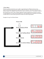
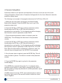
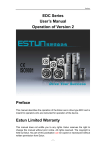
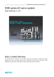
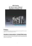
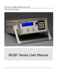
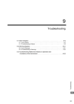
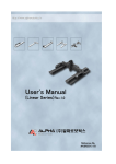
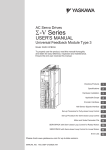
EDC Handheld Device Guide
BASIC FUNCTION
When using the handheld controller, please set the dial switch to ‘0’ on the front side of the panel of
the EDC Controller. This will allow the user to have access and control of the EDC Servo Drive
functionality with the handheld controller. This guide will familiarize the user with the basic
functionality of the handheld controller and assist with start up. The guide will cover the following:
1. Functions of the Handheld Controller
2. Status Display Mode
3. Basic Modes
4. Parameter Mode
5. Monitor Mode
6. Auxilary Mode
For more information on these functions and others, please refer to the EDC User’s Manual.
1. Functions of the Handheld Controller:
An external handheld operator can be connected to the EDC Servo Series to access parameter
settings, status monitoring, and auxiliary functions. Again, to use the handheld controller, the dial
switch on the front panel of the EDC Servo Drive must be set to ‘0’. The table below illustrates the
keys found on the handheld controller as well as their functionality. Figure 1 shows the display status
of the handheld controller on the initial start-up of the system.
Name
Function
INC KEY
Press the INC Key to increase the set value (Pressing and
keeping the INC Key held will increase the set value quicker)
DEC KEY
Press the DEC Key to decrease the set value (Pressing and
keeping the DEC Key held will decrease the set value quicker)
MODE
KEY
Press the MODE Key to select the status display mode,
parameter setting mode, monitor mode, or auxiliary
function mode. Press this key to exit the parameter setting.
ENTER
KEY
Press the ENTER Key to display the parameter settings and to
set value.
Figure 1
www.klavio.hu
2. Status Display Mode: In this mode, the digits and simple code are used to illustrate the status of
the servo drive.
Selection of Status Display Mode -The status display mode is displayed when the power is turned
ON. If current mode is not the status display mode, press the MODE Key to switch the to the required
mode.
Contents Displayed in Status Display Mode - The contents displayed in the mode are different in
Speed Control Mode and Position Control Mode.
Example: Speed Control Mode
Digits
Code
1
2
3
4
5
6
7
No.
Digital Data
Description
1
Speed
Coincidence
2
Standby
3
Control Power
is ON
4
Speed Reference
Being Input
When the reference speed input exceed the allowable value, segment is ON.
When the reference speed input is lower than an allowable value, segment is OFF.
Allowable value: 10% of rated speed.
5
Torque Reference
Being Input
When the reference torque input exceeds the allowable value, segment is ON.
When the reference torque input is lower than the allowable value, segment is OFF.
Allowable value: 10% of rated torque.
6
Main Circuit Power
Supply is Ready
Segment is ON when main circuit power supply is OK;
Segment is OFF when main circuit power supply is OFF.
7
Rotation
Detection
Output
When the offset value between the speed reference and the actual motor speed is within
an allowable value, segment is ON.
Allowable value: Pn029 (The standard value is 10 r/min)
Segment is ON when the servo is on Standby.
Segment is OFF when the servo is ON.
Segment is ON when control power of the servo drive is ON.
When the motor speed exceeds the allowable value, segment is ON.
When the motor speed is within an allowable value, segment is OFF.
Allowable value: 10% of rated speed.
www.klavio.hu
Example: Position Control Mode
Different control modes can be selected by setting the Pn041 register as seen in the table below.
Pn041 Setting
Function
0
Position Control (Pulse Reference)
Servo drive receives pulse train generated by host controller, and the control of rotation speed and
positioning are achieved according to the host controller requirements
1
Contact Speed Control (I/O Reference)
Running at a set speed is selected by switch On/Off Input Signals
2
Parameter Speed Control (Parameter Reference)
Run at a constant speed as the value in Pn048 register.
Digits
Code
1
2
3
4
5
6
7
No.
Digital Data
Description
1
Positioning
Complete
2
Standby
3
Control Power
is ON
Segment is ON when control power of the servo drive is ON.
4
Reference Pulse
Input is Continuing
When the reference pulse input is continuing, segment is ON.
When there is no reference pulse input, segment is OFF.
When the offset value between the position reference and the actual motor position is
within an allowable value, segment is ON.
Allowable value: Pn030 (The standard value is 10 pulse)
Segment is ON when the servo is on Standby.
Segment is OFF when the servo is ON.
5
Clear Signal Input is When clear signal input is continuing, segment is ON.
Continuing
When there is no clear signal input, segment is OFF.
6
Main Circuit Power
Supply is Ready
7
Rotation
Detection
Output
Segment is ON when main circuit power supply is OK;
Segment is OFF when main circuit power supply is OFF.
When the motor speed exceeds the allowable value, segment is ON.
When the motor speed is within an allowable value, segment is OFF.
Allowable value: 10% of rated speed.
www.klavio.hu
3. Basic Modes
With the handheld controller, the user is able to toggle between the different modes such as
current running status and parameter settings of the device. Below is a flow chart showing the four
different stages of the handheld controller and the order in which they occur. The operator consists of
the following basic modes: Status Display, Parameter Settings, Monitoring and Auxiliary Functions.
To toggle between the modes, press the MODE Key. Once the MODE Key is pressed in the Auxiliary
Function Mode, the user will be looped back around to the Status Display Mode.
Navigation through the different Modes:
Power ON
Status Display Mode
Parameter Setting Mode
Monitor Mode
Auxiliary Function Mode
www.klavio.hu
4. Parameter Setting Mode:
Parameters related to the operation and adjustment of the servo motor are set in this mode.
Change Parameters: Please refer to Parameter List Appendix A in the User’s Manual to know the
parameter change range.
The following is an example of changing the data stored in Pn019 from 100 to 85.
1. When the user first powers up the device the Status Display
Mode will be displayed. Press the MODE Key once to get to the
parameter setup mode.
2. Press the INC Key or DEC Key to select a parameter number.
Holding down the INC Key or DEC Key will increment or
decrement the count quicker. For this example we will be changing
the information stored in parameter number Pn019.
3. Once the desired parameter number is selected, press the
ENTER Key. This will display the data stored in the parameter
number.
4. Press the INC Key or DEC Key to select a parameter number.
Holding down the INC Key or DEC Key will increment or
decrement the count quicker. For this example we will be changing
the information stored in parameter number Pn019 from 100 to 85.
Note: When the data reaches its Maximum or Minimum value, the
value will stay unchanged even if the INC/DEC Key is pressed.
5. Once the new value is reached, press the ENTER Key. This will
cause the data to glimmer. The data is no saved in that parameter
number.
6. Press the ENTER Key again to go back to the parameter
number display.
If the MODE Key is pressed during step 3 or 4, parameter setup
operation will go directly to step 6 and no changes will be saved. If
the user needs to change any data later for another parameter, repeat
steps 2 through 6.
If Pn080 needs to be set as -32767, then a decimal point is used on
the bottom right corner of the most left number to show the current
value is negative.
Indicates Negative Value
www.klavio.hu
5. Monitor Mode:
The monitor mode can be used for monitoring the external reference values, I/O signal statuses and
internal statuses of the servo drive. Changes in Monitor Mode can be made even if the motor is
running.
1. When the user first powers up the device the Status Display
Mode will be displayed. Press the MODE Key twice to get to the
monitor mode.
2. Press the INC Key or DEC Key to select the monitor number to
be displayed. Holding down the INC Key or DEC Key will increment
or decrement the count quicker.
3. Press the ENTER Key to display the monitored data selected in
Step 2.
4. Press ENTER again to return to display the monitor number.
Monitor No.
Contents
Un000
Actual Motor Speed: r/min
Un001
Input Speed Reference: r/min
Un002
Percentage of Feedback Torque: % (Relative Rated Torque)
Un003
Percentage of Input Torque: % (Relative Rated Torque)
Un004
Number of Pulses of Encoder Angles
Un005
I/O Signal Monitor
Un006
Encoder Signal Monitor
Un007
Speed Given by Pulse (When Electronic Gear Ratio is 1:1)
Un008
Current Motor Position Low Digits
Un009
Current Motor Position High Digits
Un010
Position Reference Low Digits
Un011
Position Reference High Digits
Un012
Position Offset is 5 Digits Low Digits
Un013
Position Offset is 5 Digits High Digits
Note:
Digits to Display Internal Status
10 9
8 7
6 5
4 3
2 1
• Position pulse value is subject to electronic gear ratio of 1:1
• Unit of pulse quantity is the internal pulse unit of servo system. Pulse quantity is represented by 5 High
Digits + 5 Low Digits; the calculation method is as below:
Pulse Quantity = Value of High Digits x 10000 + Value of Low Digits.
Value of Pulse Quantity will not change any more when it reaches 327679999. The decimal point at the
bottom of the most left digit of Un008, Un010 and Un012 means the value is negative.
• When the speed given by pulse is below the electric gear ratio of 1:1, the encoder shows the theoretcial
rotation speed of the gain type 2,500 lines of the electric motor.
• Pulse numbers of the encoder angles show the rotor’s position in relation to the stator in one complete
revolution (one revolution is regarded as one cycle)
www.klavio.hu
6. Auxiliary Function Mode:
In Auxiliary Function Mode, some application operations can be done with the digial operator. The
function details are described below.
Function No.
Function
Fn000
Display Alarm History
Fn001
Restore Defaults
Fn002
JOG Operation
Fn003
Automatic Offset-Signal Adjustment of Motor Current Detection
Fn004
Software Version of Servo
Fn005
System Runtime
Example: Restore to Defaults
Upon initial startup, the EDC Servo Drive should contain factory settings. Should the user wish to
default back to the factory settings after making changes, follow the steps below:
Note: This function is used to return ALL the parameter values back to default.
1. Press the MODE Key to select auxiliary function mode.
2. Press the INC or DEC Key to select the function number for
restoring defaults (Fn001).
3. Press the ENTER Key to enter the parameter restoring mode.
4. Press and hold the ENTER Key for a second to restore all the
parameters to their default values.
5. Release the ENTER Key to return to the function number display.
6. In step 3, the parameter operation can be cancelled and to quit
the current operation by a short press on the ENTER Key.
www.klavio.hu