1
MICRO LAMBDA WIRELESS, INC.
YIG based Products
MLBS Series User Manual
MICRO LAMBDA WIRELESS, INC.
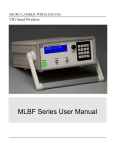
MLBS Series, Bench Test Synthesizer
User Manual
© Micro Lambda Wireless, Inc.
46515 Landing Pkwy. Fremont, CA 94538
Phone 510.770.9221 • Fax 510.770.9213
Rev A 12/20/2012
Table of Contents
Section
1.0
2.0
3.0
4.0
5.0
6.0
6.1
6.2
6.3
6.4
6.5
7.0
7.1
7.2
7.3
7.4
7.5
8.0
8.1
9.0
10.0
Description
Introduction
Package contents
General overview of product capabilities
Setup and operation
Rear panel connections
Front panel operation
Display format
Keypad function
Special keypad functions
Multi-function rotary knob operation
Settings menu
Controlling the MLBS using a personal computer
Installing the documentation and control software
HTTP information/control interface
UDP interface program
USB interface program
Telnet interface
Programming
HTTP/HTML Variables
Technical support
Warranty
1
Page
2
2
2
3
4
4
4
5
5
6
6
7
7
7
9
10
10
11
14
15
15
1.0 Introduction
This manual describes the setup and operation of the MLBS Series, Bench Test
Synthesizer. The Model and Serial numbers are located on the rear panel; they may
also be displayed on the front panel via the memory recall function and they we be
shown on the display on power-up. Each unit has a separate, custom specification
sheet for the particular model defining the Synthesizer’s frequency range and RF
characteristics. General operating/programming instructions are located herein.
The CD Rom supplied with the package contains a SetupMLBS.msi file, when
executed, will create a folder named “MLBS Support Files” on the desktop containing
short cuts to the manual, documentation and programs for interfacing the product with a
personal computer. This SetupMLBS.msi file is compatible with Windows XP, Windows
Vista and Windows 7. The most current versions of these files, new offerings and
Synthesizer specifications can be downloaded at our web site:
http://www.microlambdawireless.com
For interfacing with Apple or Linux PC’s; The HTTP and UDP protocols can be used
when connected to an Ethernet network.
2.0 Package Contents
Item
MLBS Series Bench Test Synthesizer
AC Power Cord
Ethernet CAT5 cable
USB A to USB Mini-B cable
CD Rom (Contains manual, quick start guide and PC software)
MLBS Quick Start Guide (Printed)
Quantity
1
1
1
1
1
1
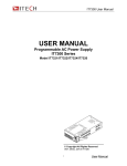
3.0 General Overview of Product Capabilities
The MLBS Series Bench Test Synthesizer can be supplied with frequency ranges
between 600 MHz and 20 GHz, in bands ranging from very narrow to very wide.
Typical, standard frequency ranges are: 0.6 to 2.5 GHz, 2.0 to 8.0 GHz, 4.0 to 16.0
GHz, 8.0 to 20.0 GHz and 2.0 to 20.0 GHz. Any custom frequency range within or
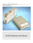
crossing most of these bands can be ordered. A simple block diagram is shown in
Figure 1. An optional reference input (i.e. 10.0 MHz) is applied to (J1) Ref. Input if
system frequency coherency is required. An internal OCXO reference with 1.0 ppm
stability is standard. The RF output (J2) supplies the microwave frequency signal at
power levels >10.0 dBm. The Synthesizer is tuned via the front panel, USB interface or
the Ethernet interface.
2
Front Panel
In
Display 2x16
REF In
CPU /
Memory
USB I/O
Frequency
control.
Optional
Synthesizer
RF Out
OCXO
Ethernet I/O
Figure 1.
4.0 Setup and Operation
This product is designed for LABORATORY WORKBENCH USE ONLY and should not
be subjected to humidity >95%. Use proper ESD handling procedures. Allow proper
intake and venting of the fan at the rear panel of the unit. Verify that all external
RF/microwave cables and components connected to the unit are in good working
condition. A grounded, three socket AC power receptacle should be used to connect
power to the unit. It is recommended that the front panel ON/OFF switch be used to
interrupt the power to the unit, interrupting power to the unit by pulling out the AC cord
may cause personal injury or damage to the unit.
Before product use, the following steps must be completed
See Figure 2 for reference.
1. Connect the AC power cable to the unit.
2. Connect the AC power cable to an appropriate 3 socket AC receptacle. The
power switch will glow RED.
3. Connect the unit REF In / RF Out connectors to the peripheral equipment using
SMA compatible connectors as required.
4. If required, connect the USB or Ethernet connectors to the Host PC or
equivalent.
5. Turn ON the unit using the front panel power switch. The power switch will now
glow GREEN after a short warm-up. (Unit will be set to last frequency setting)
6. A 15 minute warm up is recommended before use.
7. Verify the front panel display is illuminated and displaying the current frequency
setting in MHz, model number, serial number, and the fan is producing air flow at
the rear panel. The power switch LED will flash RED if the PLL is unlocked.
8. The unit is now ready for use via the front panel control or the peripheral
interfaces.
9. Note: When the AC power cable is removed from the unit, the unit will remember
its current power state and store it in nonvolatile memory for recall when the AC
voltage is reapplied.
3
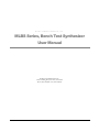
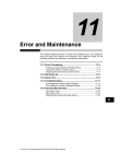
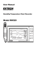
5.0 Rear Panel Connections
The rear panel of the unit is shown in Figure 2. It contains an RJ-45 plug style Ethernet
connector for interfacing to a 10/100 Mbit wired LAN, a USB Mini-B connector for
connection to a host PC USB port, and a standard 88-264 VAC, fused male input
connector for AC power input. The fuse type is a 2 amp, 250 VAC, 5x20 mm, slow blow
fuse, quantity = 2; Littlefuse part number 0213002.MRET1P or equivalent. The fuses
are accessible with the line cord removed, inside the fuse tray at the bottom of the line
Synthesizer input module. A fan input and output vent are also present and must be
kept clear of obstructions for proper operation.
The Ethernet interface is 10/100 Base-T and the USB interface is USB 1.1 and 2.0
compatible.
Figure 2
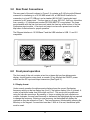
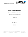
6.0 Front panel operation
The front panel of the unit contains a two line, sixteen digit per line alphanumeric
display, a multi-function rotary knob, a numeric 16 key keypad, the ON/OFF power
switch and the RF input and output connectors (See Figure 3.).
6.1 Display format
Under normal operation the alphanumeric display shows the current Synthesizer
frequency setting on the top display line (Line 1), the bottom display (Line 2) is blank. A
cursor is positioned under one of the digits on Line 1. This cursor can be positioned
using the ◄ or ► arrow keys. By pressing +/- keys or rotating the knob clockwise or
counter clockwise, the user can increment or decrement the highlighted digit as required
to change the frequency. Entering a new frequency via the keypad will display the
numbers as they are entered on Line 2. The new frequency is selected by pressing the
MHz key on the keypad. If a resolution less than 1 MHz is to be set, the decimal point
must be used.
4
Figure 3
6.2 Keypad function
Press the ► key on the front panel to move cursor right or when in the settings menu,
go to the next menu selection.
Press the ◄ key on the front panel to move cursor left, to backspace data entry, or
when in the settings menu, go to the previous menu selection.
Press the + key on the front panel to increment cursor position or enable a menu option.
Press the - key on the front panel to decrement cursor position or disable a menu
option.
Enter numbers and decimal point via the keyboard as needed.
The MHz key is also used as the data entry key.
6.3 Special keypad functions
1. Displaying a nonvolatile memory location
Press the decimal point key on the keypad, the display will show R_ (for recall).
Enter the desired NOVO location using the number keys and press the MHz key.
The information located at the requested NOVO location will be displayed on line
#2 of the front panel display. Valid NOVO locations are: 0 to 2047. See the list of
NOVO locations in section 8.0, Programming.
2. Saving and recalling a user preset frequency from memory (0-99)
The user can store up to 100 preset frequencies in memory for later recall.
To save a frequency, enter a frequency on the front panel to store in memory and
press MHz. Line #1 of the display will show the frequency entered and the unit
will be set to this frequency. Press the MHz key again to enter the Save / Recall
menu. The display will show “Save = + Recall = -“. Press the “+” key to enter
save mode or press the “–“ key to enter recall mode. Pressing the “+” key will
display on Line #2 “Save Setting ?”. Enter the memory location you would like to
store this frequency in (0-99). The display will show the memory location
numbers as you enter them. Press the MHz key to save your frequency
5
in the desired location. To recall a frequency from a stored location, press the
MHz key. The display will show “Recall Setting ?” on Line #1 of the display. Enter
the number for the memory location you would like to recall (0-99), the numbers
you have entered will be displayed on Line #2. Press the MHz key to recall the
frequency setting from memory. The unit will be set to the recalled frequency. If a
memory location is recalled where no frequency has been stored, the display will
not change and the unit will stay at the current frequency setting. Note: The
frequencies stored in memory 0 to 99 can be viewed by recalling NOVO locations
200 to 299.
6.4 Multi-function rotary knob operation
The knob, when rotated clockwise = increment; counter clockwise = decrement
(equivalent to + or - key press).
Press the encoder knob on the front panel to enter the SETTINGS MENU.
Press the encoder knob again if you wish to exit the SETTINGS MENU. Upon exit, the
changes made while in the settings menu mode, will be enabled.
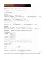
6.5 Settings menu operation
Pressing the Multi-function knob enters the SETTINGS MENU. The following functions
can be set:
1.
Ethernet DHCP:
ON
2.
IP Address:
192.168.1.48
3.
Subnet Mask:
255.255.255.0
4.
Gateway:
192.168.1.1
5.
DNS1:
192.168.1.1
6.
DNS2:
0.0.0.0
7.
MAC Address:
0004A31210EE
8.
Host Name:
MLBS0001
9.
UDP Port:
30303
Press the encoder knob on the front panel to enter the
SETTINGS MENU.
Display #1. On the left will be visible.
Press the encoder knob again if you wish to exit the SETTINGS
MENU.
Press the ► key on the front panel for the next menu selection.
Press the ◄ key on the front panel for the previous menu
selection or data entry backspace.
The knob, when rotated clockwise = increment; counter clockwise
= decrement.
Press the + key on the front panel to enable an option.
Press the - key on the front panel to disable an option.
Enter numbers and decimal point via the keyboard as needed.
MHz key is also used as the enter key.
Note:
1. MAC address cannot be changed.
2. Host name cannot be changed.
3. All fields can be edited via the web interface (http://(units
IP Address).
4. When DHCP mode is ON, IP Address, Subnet mask,
Gateway and DNS settings cannot be changed.
6
7.0 Controlling the MLBS using a personal computer
7.1 Installing the documentation and control software
The CD ROM supplied with the MLBS contains the file named SetupMLBS.msi.
Execute this file to install the manual, documentation and control programs for PC
interface. The setup file, when run, will create a folder named “MLBS Support Files” on
the computer desktop with short cuts to the documentation and interface programs.
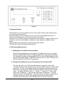
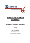
7.2 HTTP Control Interface
This HTTP interface is accessed using a PC running a standard web browser (IE8,
Firefox 3.6). The PC must be physically connected to the same TCP/IP network as the
MLBS unit and have the correct Ethernet configuration (same “IP” range and subnet
mask). The Ethernet settings can be accessed through the settings menu as mentioned
in the previous section. To access the MLBS unit, point your web browser to the IP
address or use the host name of the unit (e.g. http://192.168.1.48 or e.g.
http://MLBS0001 ). The “MLBS Settings Page” will be displayed. This web page
contains general information about the unit and allows the configuration of the Ethernet
settings. Also available is the function to send and receive a command to and from the
unit. An example of the page is shown in Figure 4. Links at the bottom of this page
direct your browser to the following web pages.
Links to two other web pages are available as follows: Located at the lower left of the
settings page is a link to the “MLBS Diagnostics Page”. Here you can view many of
the unit’s internal variables like temperature, power supply voltages, self test status, cal
status, miscellaneous technical data, and contact information for Micro Lambda
Wireless, Inc. Commands may also be sent to the unit from this web page.
The last web page accessible is the “MLBS Commands List Page”. This page lists all
of the commands accepted by the MLBS unit and the NOVO locations that can be read
using the “R” command. The ability to send and receive commands is also available on
this page. These commands can be used under USB control as well.
7
Figure 4
8
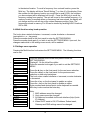
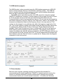
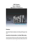
7.3 UDP Interface program
The MLBS (Host) may be controlled remotely over an Ethernet network using the
supplied “MLBS UDP interface.exe” program. Please note: Windows firewall may warn
that a new program is trying to access the network, please click “Allow”, to continue
using the MLBS UDP interface program. The PC used to connect to the unit is
considered the “Client”. The unit must be physically connected to the network as
mentioned in section 7.2 above. In the lower left corner of the program screen as shown
in Figure 7, type in the Host name or I.P. address of the unit you wish to communicate
with, also input the socket port number that your unit is set to. See section 6.5 to find
the unit’s network settings information. Click the “Test Connection” button and the
program should connect to the unit stated and the display should read connected. On
the program screen you will see some limited information about the unit. Commands
may be sent to and received from the unit. The unit can also be stepped up and down in
frequency using the “Step Up” and “Step Down” buttons. The frequency will increment
and decrement based on the frequency shown in the step size box. This number can be
changed to any valid step size within the frequency range limits of the unit. Sweep
modes of Auto (Continuous), Single, Manual and List are available. Dwell Time is the
amount of time, in milliseconds, that the unit will pause at each frequency before
stepping to the next frequency. The current frequency setting is also shown. The
program can be used to connect to multiple units (one at a time). As connections are
made, the unit Host names will be added to the pull down list in the Host Name/IP
Address box.
Figure 7
9
7.4 USB Interface program
The MLBS product, when connected using the USB interface appears as a USB HID
device (Human Interface Device) to the Windows operating system. The USB HID
driver is supplied with the windows operating system, and is installed automatically
when the unit is connected to the PC’s USB port.
The MLBS may be controlled remotely via a USB connection using the supplied
“MLBS PC interface.exe” program. A screen capture of this program is shown in Figure
8. On the program screen you will see some limited information about the unit.
Commands may be sent to and received from the unit. The unit can also be stepped up
and down in frequency using the “Step Up” and “Step Down” buttons, the frequency will
increment and decrement based on the frequency shown in the step size box. This
number can be changed to any valid step size within the frequency range limits of the
unit. The current frequency setting is also shown along with Start and Stop frequencies
for sweep mode. Sweep modes of Auto (Continuous), Single, Manual and List are
available. Dwell Time is the amount of time, in milliseconds, that the unit will pause at
each frequency before stepping to the next frequency. The program can be used to
connect to multiple units; all units that are connected to the PC’s USB ports will show up
in the pull down list in the “Choose Unit #” box. If units are added after the program has
been initiated, press the “Refresh” button to update the list. Sweep mode only supports
connection to one unit at a time.
Figure 8
7.5 Telnet Interface
Built into most computer operating systems is a command line interface for
communicating with network peripherals; TELNET is a network protocol used on the
Internet or local area networks to provide a bidirectional, interactive text-oriented
communication facility via a virtual terminal connection. In the Microsoft Windows
10
environment, Telnet is invoked via the command prompt mode (Note: In Windows 7
Telnet is not enabled by default, to enable it, go to control panel, programs and
features, on the upper left of the screen select “Turn Windows features on and off”,
check “Telnet Client” and click OK.). At the DOS prompt type “telnet”. The following
information will appear:
Welcome to Microsoft Telnet Client
Escape Character is 'CTRL+]'
Microsoft Telnet>
Type ?/help for a list of Telnet commands. Using Telnet, you can send commands to
the unit and receive information requested from the unit. A typical session would be:
Send – “o MLBS0005 23”, this opens a telnet connection to the unit MLBS0005 on port
23 (Typical comm. Port for telnet). Send – “F2000”, this would set the unit to a
frequency of 2000.0 MHz. Send “T”, the internal temperature of the unit will be returned.
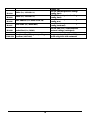
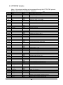
8.0 Programming
The following table describes the commands that the MLBS supports. This is a custom syntax
created by Micro Lambda Wireless, Inc. All commands are sent and received in ASCII format.
The commands are NOT case sensitive. These commands can be used with all forms of
communication (USB, UDP, HTTP and Telnet). Note: All Non-volatile memory locations below
may be recalled from the front panel and displayed on the LCD by pressing the decimal key (.)
followed by the memory location number (leading zero’s are not required). The information will
be displayed on line 2 of the front panel display. Example: press (.) 0 to recall Model number.
Available when NOVO is locked: Commands are not case sensitive. Command ? "" DI DR DT EP Function Report Status Display the message between the quotes on LCD display, line 1 & 2. Display Personality information on lines 1 and 2 (Takes 15 seconds to disp) Display recalled NOVO memory location on FP readout, line 2 Display current internal temperature on FP readout, line 2 Set Ethernet Port (Socket Port); i.e. EP30303, stored at NOVO Loc. 108 F Frequency (ASCII) (Dec. #) L Set Level for the RF Power control option 11
All Data is stored in locations and Sent / Received is in ASCII format Comments (PW) = PIC writes to this or another NOVO location. D0 = 100 MHz lock, D1 = YIG PLL lock, D6 = self test, D7 = NOVO lock "Have a nice day!": Displays Have a nice day! (up to 32 characters) DI (i.e. DR0012), display firmware version and date DT UDP, TCP Socket Port ASCII freq in MHz: xxxxx.xxxxxx; (example: F12345.678910) Sets the Leveling Circuit to a specific Level (L-0.5) LR MR MS R SP SR ST T V1 V2 V3 V4 V5 R 0000 R 0001 R 0002 R 0003 R 0004 R 0005 R 0006 R 0007 R 0008 R 0009 R 0010 R 0011 R 0012 R 0013 R 0014 R 0015 Level Cal NOVO Read Recall a user saved frequency setting from memory location (MR25) Save current frequency setting of unit to memory location (MS75) Read NOVO location (Example = R1 = read serial #) Synthesizer preset to factory settings. Leveling NOVO read 0-99, stored @ NOVO location 200-299 0-99, stored @ NOVO location 200-299 returns info @ memory location requested (0-2047) Copy NOVO Loc. 900-960 to 0-60 Reset PIC, clear var. run PIC code from Soft PIC Reset start; (example: SR) Read status byte D2; 1 = Pass; (example: Self Test SR, then read data) Returns ASCII chars, reading in Deg. C; Read internal temp. (example: T, then read data) 3.00V = normal; (example: V1, then read Read Power Supply +3.0V data) 3.30V = normal; (example: V2, then read Read Powe +3.3V data) 5.00V = normal; (example: V3, then read Read Internal +5.0V data) 15.00V = normal; (example: V4, then read Read internal +15.0V voltage data) -15.00V = normal; (example: V5, then read Read internal -15.0V voltage data) Model Number (Example = W0001 or R1) MLBS-2080C ("W" blocked with NOVO Write or Read Location. locked.) (R/W = 16 Bytes) Serial Number ("W" command requires 4 numeric digits), R1 reads Loc. 1 1125 Product type: Filter or Oscillator or Defines how PIC will talk to internal, Synthesizer connected device 2000 (unit is tunable 100.0 MHz below Fmin, in MHz Fmin.) 8000 (unit is tunable 100.0 MHz above Fmax, in MHz Fmax.) Current YIG PLL Chip Input - Reference Ref# = 1 – 200 MHz (typically 100.0 MHz, Frequency Setting - MHz OCXO) RF min, in dBm 10.0 RF max, in dBm 15.0 Temp min, in Deg. C 0 Temp max, in Deg. C 60 Highest Temp reached, in Deg. C 35.7C NOVO State - Locked/Unlocked Locked Firmware Version & date 1.5 Nov 16 2011 Unit Health Status – “Good” or Self test failure information “Good” or “Fail V5” as example Unit Calibration Status - Yes/No Yes Self Test Results - Pass/Fail Pass 12
R 0016 R 0017 R 0029 R 0031 R 0032 R 0033 R 0034 R 0035 R 0036 R 0037 R 0038 R 0039 R 0040 R 0041 R 0042 R 0043 R 0044 R 0045 R 0048 R 0050 R 0051 R 0056 R 0057 R 0058 R 0059 …. R 0100 R 0101 R 0102 R 0103 Current Output Frequency setting - MHz Internal Xtal Setting – Int or Ext or ExtXtal External reference freq. In MHz for 100 MHz PLL (ExtXtal mode) Customer part number, if shown on P.O. Frequency resolution in MHz (or Step Size) Spurious Spec., in dBc Harmonics Spec., in dBc Phase Noise Spec. @ 100 Hz Offset, in dBc/Hz Phase Noise Spec. @ 1 kHz Offset, in dBc/Hz Phase Noise Spec. @ 10 kHz Offset, in dBc/Hz Phase Noise Spec. @ 100 kHz Offset, in dBc/Hz Phase Noise Spec. @ 1 MHz Offset, in dBc/Hz Switching Speed, any step, in mS TCP/IP stack version Firmware build time Level Control Option installed? Level Control Maximum Power Limit, in dB Level Control Minimum Power Limit, in dB Current RF Level Setting, in dBm Level Control CAL Status (Is Level option calibrated) Level flatness Spec. in +/- dB (+/- 2.0 = 4.0 total) Internal Synthesizer Model Number Internal Synthesizer Serial Number MLWI Sales (Job) number MLWI Product Outline Drawing # and Revision DHCP Status: ON / OFF IP address: (i.e.; 192.168.1.25) Subnet mask: (i.e.; 255.255.255.0) Gateway: (i.e.; 192.168.1.1) 13
2500 ExtXtal (3 modes; Internal Xtal, External and External with Xtal.) i.e.: 10 = 10 MHz external reference. 1.0 MHz increments only 123-45-6789 (Shown on unit label as PN:) 0.001 = 1.0 kHz -60 -12 -80 -95 -95 -117 -140 5.0 v5.20 16:30:30 Yes / No / Fixed (mode select) If fixed, min, max and set level = same (10 dBm) 10.0 -10.0 9.5 Yes / No 2.0 MLSP-2020BD 2255 20-0024 201-001 A Static = OFF / Auto = ON TCP/IP Ethernet settings (config_dhcpchecked) TCP/IP Ethernet protocol settings (config_ip) TCP/IP Ethernet protocol settings (config_subnet) TCP/IP Ethernet protocol settings R 0104 R 0105 R 0106 R 0107 DNS1: (i.e.; 192.168.1.1) DNS2: (i.e.; 192.168.1.1) MAC Address: (i.e. 0025F169AC1B) Host Name (i.e.; MLBF0001) R 0108 …. Socket Port (i.e.; 30303) User Save / Recall Frequency setting R 200-299 locations (100 Total) 14
(config_gw) TCP/IP Ethernet protocol settings (config_dns1) TCP/IP Ethernet protocol settings (config_dns2) TCP/IP Ethernet protocol settings (config_mac) TCP/IP Ethernet protocol settings (config_hostname) TCP/IP UDP, TCP, Telnet Ethernet protocol settings (socketport) Frequency stored in MHz (ASCII), save and recall using MS & MR commands 8.1 HTTP/HTML Variables
Many of the internal variables can be accessed through the HTTP/HTML protocol.
Below is a list of these variables for reference:
Command
HTML variable name
Notes
?
status
Read/Write?
Read
Report Status, D2-D5 not used
T
temp
Read
Internal temperature
V1
volt1
Read
Read power supply: +3.0V voltage
V2
volt2
Read
Read Power supply: +3.3V voltage
V3
volt3
Read
Read Power supply: +5.0V voltage
V4
volt4
Read
Read Power supply: +15.0V voltage
V5
volt5
Read
Read Power supply: -15.0V voltage
R0000
model
Read
Model Number
R0001
serial
Read
Serial Number
R0002
product
Read
Product type: Synthesizer / Oscillator / Synthesizer
R0003
minimum
Read
Frequency minimum
R0004
maximum
Read
Frequency maximum
rfmin
Read
RF min, in dBm
rfmax
Read
RF max, in dBm
tempmin
Read
Temp min, in Deg. C
tempmax
Read
Temp max, in Deg. C
hitemp
Read
Highest Temp reached, in Deg. C
novostate
Read
NOVO State - Locked/Unlocked
firmver
Read
Firmware Version & date
health
Read
Unit Health Status – “Good” or Self test failure information
cal
Read
Unit Calibration Status - Yes/No
selftest
Read
Self Test Results - Pass/Fail
Current Output Frequency setting - MHz
R0029
frequency
version
Read
Read
TCP/IP Stack Version
R0030
builddate
Read
Firmware Build Time
freqres
Read
Frequency resolution in MHz (or Step Size)
spurs
Read
Spurious Spec., in dBc
harmonics
Read
Harmonics Spec., in dBc
pn100
Read
Phase Noise Spec. @ 100 Hz Offset, in dBc/Hz
pn1k
Read
Phase Noise Spec. @ 1 kHz Offset, in dBc/Hz
pn10k
Read
Phase Noise Spec. @ 10 kHz Offset, in dBc/Hz
pn100k
Read
Phase Noise Spec. @ 100 kHz Offset, in dBc/Hz
pn1m
Read
Phase Noise Spec. @ 1 MHz Offset, in dBc/Hz
speed
Read
Switching Speed, any step, in mS
version
Read
TCP/IP stack version
builddate
Read
Firmware build time
lvlopt
Read
Level Control Option installed?
lvlmin
Read
Level Control Maximum Power Limit, in dB
Level Control Minimum Power Limit, in dB
R0100
lvlmax
config_dhcpchecked
Read
Read
DHCP Status: ON / OFF
R0101
config_ip
Read
IP address: (i.e.; 192.168.1.25)
R0102
config_subnet
Read
Subnet mask: (i.e.; 255.255.255.0)
R0103
config_gw
Read
Gateway: (i.e.; 192.168.1.1)
R0104
config_dns1
Read
DNS1: (i.e.; 192.168.1.1)
R0105
config_dns2
Read
DNS2: (i.e.; 192.168.1.1)
R0106
config_mac
Read
MAC Address: (i.e. 0025F169AC1B)
config_hostname
Read
Host Name: (i.e. MLBS0001)
socketport
cmd (=)
Read
Write
UDP Socket Port: (i.e. 30303)
Send any of the commands in table from section 8.0
receive
Read
Receive data from unit after requesting data
R0006
R0007
R0008
R0009
R0010
R0011
R0012
R0013
R0014
R0015
R0016
R0032
R0033
R0034
R0035
R0036
R0037
R0038
R0039
R0040
R0041
R0042
R0043
R0044
R0045
R0107
R0108
15
9.0 Technical Support
For Technical support please contact:
Micro Lambda Wireless, Inc.
46515 Landing Pkwy.
Fremont, CA 94538
Ph: (510) 770-9221
Fax: (510) 770-9213
Email: [email protected]
You can visit our website at http://www.microlambdawireless.com for updated
information, specifications and downloads.
10.0 Warranty
Seller warrants for a period of twelve (12) months from the date of original shipment that
the products will be free from defects in material and workmanship and design (if of
Micro Lambda Wireless, Inc. design) and will be in conformity with applicable
specifications and drawings and all other contractual requirements. However, this
warranty shall not apply to any product which that has been subjected to misuse,
misapplication, accident, improper installation, neglect, unauthorized repair, alteration,
adjustment, inundation or fire. See the complete warranty and return policy document
number 201-005 Rev- at our website at http://www.microlambdawireless.com.
16