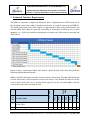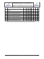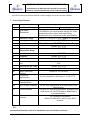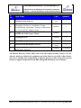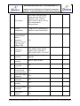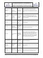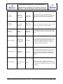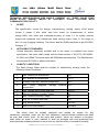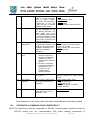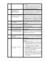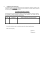
1
Volume – II Technical Section ADVANCED METERING INFRASTRUCTURE (AMI) SYSTEM TENDER REFERENCE No. WB/DH/2014/G-04/ R-14.08.2014 DAKSHIN HARYANA BIJLI VITRAN NIGAM LTD Implementation of AMI System for selected LT connections (Volume II – Technical Specification of the Tender Document) Table of Contents Section 1.0: Abbreviations........................................................................................................................... 3 Section 2.0: About DHBVN .......................................................................................................................... 6 Section 3.0:- About Existing IT and R-APDRP System ................................................................................... 8 Section 4.0: Scope of Work ........................................................................................................................ 12 Section 5.0: Qualification Criteria .............................................................................................................. 26 Section 6.0: Bid Evaluation Methodology .................................................................................................. 32 Section 7.0: Payment Terms ...................................................................................................................... 36 Section 8.0: Estimated Man-Power Requirement ...................................................................................... 39 Section 9.0: Estimated Timelines Requirement ......................................................................................... 43 Section 10.0:- Functional Specifications of AMI System ............................................................................ 46 Section 11.0: Project Management ........................................................................................................... 59 Section 12.0: Documentation .................................................................................................................... 66 Section 13.0: Inspection, Testing & Operational Acceptance..................................................................... 72 Section 14.0: Functional and Technical Specifications of Smart Meter ...................................................... 85 Section 15.0: Technical Specifications of Data Concentrator Unit (DCU) ................................................. 119 Section 16.0: Meter Data Management Specifications ............................................................................ 126 Section 17.0: Technical Specifications of Head End System ..................................................................... 143 Section 18.0: Functional Requirements for Business Intelligence, Analytics & reporting ........................ 148 Section 19.0: AMI Network Backhaul ...................................................................................................... 154 Section 20.0: Operation and Maintenance Services and SLA ................................................................... 160 Section 21.0: Bill of Material ................................................................................................................... 180 Section 22.0: IT Equipment’s Specifications............................................................................................. 184 Section 23.0: Technical Use Cases............................................................................................................ 199 WB/DH/2014/G-04/R Dated 14/08/2014 Volume II – Technical Part of Tender Document Page 2 of 207 DAKSHIN HARYANA BIJLI VITRAN NIGAM LTD Implementation of AMI System for selected LT connections (Volume II – Technical Specification of the Tender Document) Section 1.0: Abbreviations WB/DH/2014/G-04/R Dated 14/08/2014 Volume II – Technical Part of Tender Document Page 3 of 207 DAKSHIN HARYANA BIJLI VITRAN NIGAM LTD Implementation of AMI System for selected LT connections (Volume II – Technical Specification of the Tender Document) ABT ACL AMI AMI-IA API AT&C (Loss) BCS CDMA CMRI CPP DCU DHBVN Discom DMS DPR DR DT / DTR ERP FPI GIS HES HHU IEC IST LAN LF MDAS MDMS MIS MPLS NIPS NMS OEM PAN R-APDRP RTC Availability Based Tariff Access Control List Advanced Metering Infrastructure AMI Implementing Agency (or Selected Bidder) Application Programming Interface Aggregate Technical and Commercial (Loss) Base Computer Station Code Division Multiple Access Common Meter Reading Instrument Critical Peak Pricing Data Concentrator Units Dakshin Haryana Bijli Vitran Nigam Limited Distribution Company Document Management System Detailed Project Report Demand Response Distribution Transformers Enterprise Resource Planning Fault Passage Indicator Geographical Information System Head End System Hand Held Unit International Electro-technical Commission Indian Standard Time Local Area Network Load Factor Meter Data Acquisition System Meter Data Management System Management Information System Multi Protocol Label Switching Network based intrusion detection system Network Management System Original Equipment Manufacturer Permanent Account Number Restructured Accelerated Power Development and Reforms Program Real Time Clock WB/DH/2014/G-04/R Dated 14/08/2014 Volume II – Technical Part of Tender Document Page 4 of 207 DAKSHIN HARYANA BIJLI VITRAN NIGAM LTD Implementation of AMI System for selected LT connections (Volume II – Technical Specification of the Tender Document) SAN SCADA SMN SOA ToD ToU UI UPS VEE VPN XML Storage Area Network Supervisory Control and Data Acquisition Smart Meter Network Service Oriented Architecture Time of Day Time of Use Unscheduled Interchange Uninterrupted Power Supply Data Validation, Estimation and Editing Virtual Private Network Extensible Markup Language WB/DH/2014/G-04/R Dated 14/08/2014 Volume II – Technical Part of Tender Document Page 5 of 207 DAKSHIN HARYANA BIJLI VITRAN NIGAM LTD Implementation of AMI System for selected LT connections (Volume II – Technical Specification of the Tender Document) Section 2.0: About DHBVN WB/DH/2014/G-04/R Dated 14/08/2014 Volume II – Technical Part of Tender Document Page 6 of 207 DAKSHIN HARYANA BIJLI VITRAN NIGAM LTD Implementation of AMI System for selected LT connections (Volume II – Technical Specification of the Tender Document) 1. About DHBVN The Haryana Electricity Reform Act, 1997 (Act No. 10 of 1998) was passed by the Haryana State Legislative Assembly on 22nd July, 1997. After receiving the Presidential assent on 20th Feb.1998, this Act came into force on 14th August, 1998. The erstwhile Haryana State Electricity Board was unbundled into two corporate bodies namely Haryana Power Generation Company Limited for the generation of power and Haryana Vidyut Prasaran Nigam Limited for the transmission & distribution of power within the state of Haryana. Subsequently, the activity of distribution and retail supply of power was entrusted with effect from 1st July 1999 to Uttar Haryana Bijli Vitran Nigam for the northern circles and Dakshin Haryana Bijli Vitran Nigam for the southern circles of Haryana – Gurgaon, Faridabad, Bhiwani, Hisar, Sirsa and Narnaul. Dakshin Haryana Bijli Vitran Nigam (DHBVN) is head-quartered in Hisar and is responsible for distribution and retail supply of electricity in the southern parts of Haryana covering the districts of Faridabad, Palwal, Gurgaon, Mewat, Rewari, Mahendragarh, Bhiwani, Hisar, Fatehabad, Jind and Sirsa. DHBVN provides services to approx. 28.3 lakh consumers of various categories. DHBVN currently operates through nine operation circles viz. Faridabad, Palwal, Gurgaon, Narnaul, Rewari, Bhiwani, Hisar, Jind and Sirsa. Category-Wise Total Consumer Base of DHBVN in each Circle Category Domestic Supply Faridabad Palwal Gurgaon Narnaul Rewari Bhiwani Hisar Sirsa Jind DHBVN 327522 216845 284077 125380 170081 249156 416379 208323 200154 2197917 Non Domestic Supply 42168 21868 42168 21868 39755 13888 16201 23585 20705 256616 Agriculture - Metered 7128 17415 11849 13874 16706 28410 36494 40324 22799 194999 Agriculture - Un Metered 1234 4405 8452 16375 12793 10643 14036 10537 14904 93379 180 11 269 17 25 89 147 134 45 917 1870 2184 965 1446 609 1247 1067 750 639 10777 LT Industrial 19712 3081 8737 1185 1745 2249 5065 3008 2228 47010 HT Industrial 1975 477 2071 170 327 614 522 178 232 6566 51 41 273 13 23 48 65 28 33 575 Railway Traction 1 0 2 0 0 0 0 0 0 3 HT Public Water Works 3 4 3 5 4 20 35 1 3 78 24268 0 0 12 0 0 15 0 0 24295 426112 266331 356453 172365 218514 316059 524611 290945 261742 2833132 Street Light LT Public Water Works Bulk Supply HT Others Total *Figures as on March’ 2014 WB/DH/2014/G-04/R Dated 14/08/2014 Volume II – Technical Part of Tender Document Page 7 of 207 DAKSHIN HARYANA BIJLI VITRAN NIGAM LTD Implementation of AMI System for selected LT connections (Volume II – Technical Specification of the Tender Document) Section 3.0:- About Existing IT and RAPDRP System WB/DH/2014/G-04/R Dated 14/08/2014 Volume II – Technical Part of Tender Document Page 8 of 207 DAKSHIN HARYANA BIJLI VITRAN NIGAM LTD Implementation of AMI System for selected LT connections (Volume II – Technical Specification of the Tender Document) 1. Information About Legacy and R-APDRP Scheme of DHBVN The Ministry of Power, Government of India has sanctioned R-APDRP PART-A IT implementation projects in both the power distribution utilities of the state of Haryana. The project is in advanced stage of implementation and is being carried out by M/s HCL Technologies Ltd., ITImplementation Agency (ITIA). The R-APDRP Part-A (IT) scheme envisages preparation of Base-line data for the project area covering GIS based Consumer Indexing and Asset Mapping of the entire distribution network and Automatic meter reading of Distribution Transformers, HT Consumers, Feeders and Boundary meters. It includes adoption of IT applications for new connections and disconnections; meter reading, billing & collection; energy accounting and auditing; MIS; redressal of consumer grievances through establishment of IT enabled consumer service centers etc. The scheme consists of establishment of Data Center (DC), Customer Care Center (CCC), Disaster Recovery Center (DR) and integration of various utility offices in the eligible towns with Central Data Center. All business applications are hosted at Data Center and are accessible to other office users through a secured and reliable MPLS link connectivity. GPRS network is used to enable acquiring of data from metering nodes for undertaking proper Energy Audit at DHBVN. The R-APDRP Part-A (IT) program is being implemented in 18 towns of DHBVN. The salient features of the program are:a. b. c. d. Centralized Data Centre to be established at Hisar Common Centralized Call Centre at Gurgaon for a seating capacity of 100 Disaster Recovery Centre at Panchkula The following modules and systems are to be provided: i. Meter Data Acquisition System ii. Energy Audit iii. New Connection iv. Disconnection & Dismantling v. GIS based Customer Indexing and Asset Mapping vi. GIS based Network Analysis Module vii. Centralized Customer Care Services viii. Management Information System (MIS) ix. Web Self Service x. Identity & Access Management System xi. System Security Requirement xii. Development of Commercial Database of Consumers WB/DH/2014/G-04/R Dated 14/08/2014 Volume II – Technical Part of Tender Document Page 9 of 207 DAKSHIN HARYANA BIJLI VITRAN NIGAM LTD Implementation of AMI System for selected LT connections (Volume II – Technical Specification of the Tender Document) xiii. Metering xiv. Billing xv. Collection xvi. Asset Management xvii. Maintenance Management xviii. Document Management System xix. Mail / Messaging System xx. Enterprise Management System and Network Management System xxi. Antivirus & Firewall System xxii. Data Warehouse System with MIS Application e. AMR Implementation of Distribution Transformers, Substations, HT and select LT Consumers f. DGPS based GIS Survey for all towns coming under the scheme g. Establishment of LAN, MPLS-VPN and other networking in all the identified offices h. Facility Management System for 5 years from “Go-Live” date of project Solution Mapping With R-APDRP Modules in DHBVN SCADA system implementation in Faridabad town is envisaged under the R-APDRP Program. DHBVN is currently in the process of selection of SCADA Implementing Agency (SIA). WB/DH/2014/G-04/R Dated 14/08/2014 Volume II – Technical Part of Tender Document Page 10 of 207 DAKSHIN HARYANA BIJLI VITRAN NIGAM LTD Implementation of AMI System for selected LT connections (Volume II – Technical Specification of the Tender Document) Details of Core Product in the R-APDRP Solution Name of Product Oracle Utilities Customer Care and Billing Module Details Oracle Utilities Customer Care and Billing: Oracle Utilities Customer Care and Billing Rating and Billing Residential Customers Oracle Utilities Customer Care and Billing Extractors and Schemas Customers Oracle Utilities Customer Care and Billing Business Intelligence Enterprise Edition Oracle Utilities Business Intelligence (for Oracle Utilities Customer Care and Billing) Oracle Utilities Work and Asset Management Oracle Utilities Work and Asset Manager GIS Adapter Oracle Utilities Business Intelligence (for Oracle Utilities Work and Asset Management Oracle Utilities Work and Asset Management Standard Edition Oracle Utilities GIS Integration. Integrations between Oracle ESRI ArcGIS Utilities Work and Asset Management and GIS systems are twoway communications. Oracle Utilities Work and Asset Management Business Intelligence Standard Edition Oracle Utilities Work and Asset Management Extractors and Schemas Work and Asset Management are loaded into the Oracle Utilities Business Intelligence STAR schema. Includes Extractors and STAR schema ArcGIS Server Advance Enterprise with Arc Schematic Server Extension & Network Analyst Server Extension ArcGIS Server Basic Enterprise ArcFM Server for ArcGIS Server Advance ArcGIS Arc Editor with Arc Schematic Extension & Network Analyst Extension ArcFM ArcGIS DI Extension (Concurrent) Conduit Manager Network Adapter GIS based Network Analysis PRDC CA Identity manager CA Identity Manager is used for user provisioning, password CA IDM Suit CA Directory server enterprise edition (LDAP server) management, auditing for various resources. This is used for Single sign on, authentication, authorization, federation of web applications and web services. LDAP server. WB/DH/2014/G-04/R Dated 14/08/2014 Volume II – Technical Part of Tender Document Page 11 of 207 DAKSHIN HARYANA BIJLI VITRAN NIGAM LTD Implementation of AMI System for selected LT connections (Volume II – Technical Specification of the Tender Document) Section 4.0: Scope of Work WB/DH/2014/G-04/R Dated 14/08/2014 Volume II – Technical Part of Tender Document Page 12 of 207 DAKSHIN HARYANA BIJLI VITRAN NIGAM LTD Implementation of AMI System for selected LT connections (Volume II – Technical Specification of the Tender Document) 1. Detailed Scope of Work The scope of work is to design, supply, establish, operate and maintain Advanced Metering Infrastructure (AMI) for approx. 78500 connections (equipped with Three Phase Whole Current meters and having sanctioned load ranging from 10 KW to 20 KW) of DHBVN spread over Gurgaon and Faridabad circles. 1. Complete system is to be established by selected AMI Implementation Agency (AMI-IA) within 24 months from the date of award of work and thereafter the same agency to provide O&M support for five years. 2. The operation & maintenance (O&M) period will be reckoned from the date of complete roll out as per time schedule mentioned in project schedule. The agency will also be responsible for the partial operations of the system during the implementation phase. 3. Proposed AMI System should be scalable in nature taking into consideration an average growth rate of consumers and associated infrastructure to be 7.5 % per annum for the complete project duration from the date of award of contract. Enterprise-wide license for the software components is a mandatory requisite. Proposed infrastructure at Back End in Data Center (DC) and Disaster Recovery Center (DRC) should be scalable to handle all connections of DHBVN i.e. 3 millions. 4. The scope of work shall include, in complete conformity with subsequent sections of the specifications, site survey, planning, design, engineering, manufacturing, supply, transportation & insurance, delivery at site, unloading, handling, storage, installation, integration, configuration, testing, commissioning, demonstration for acceptance, training, operation, maintenance and documentation of :a) b) c) d) e) f) Three Phase Smart Meter (Electronic whole current energy meters with 1060Amp & 10-100Amp (As per the DHBVN’s specification No CSC48/RIII/DH/UH/P&D/2012-13) with suitable in-built communication technology and remote connect-disconnect relay) Meter Cover Boxes (Polycarbonate as per DHBVN’s specification) Data Concentrator Units (DCU)/Repeaters with suitable in-built communication facilities All associated hardware and accessories for installation of Smart Meter & DCU such as wire, box, wooden board etc. Head End System for Data Acquisition Meter Data Management System WB/DH/2014/G-04/R Dated 14/08/2014 Volume II – Technical Part of Tender Document Page 13 of 207 DAKSHIN HARYANA BIJLI VITRAN NIGAM LTD Implementation of AMI System for selected LT connections (Volume II – Technical Specification of the Tender Document) g) h) i) j) k) l) m) n) o) p) q) r) s) Business Intelligence & Analytics Tools Implementation of AMI features as per tender specifications AMI Control center hardware and software such as Server, Workstations, Storage, Network and Cyber Security Equipment’s, Operating Systems, Database Software, Anti-Virus Software, MS-Office for Workstations, etc. Initial Site Survey to capture the field details wherever required for system designing and for finalization of BoQ. Integration with R-APDRP Part-A (IT) System and Existing Billing System Integration with ERP and SCADA (Planned under R-APDRP) System Planning, deployment, tuning, operation and maintenance of end to end communication system to meet performance requirements as specified in the bidding document. All cabling associated with AMI Control Center hardware, communication systems and power supply source. To implement all minor civil works necessary for installation of proposed equipment and provide the details of such civil works to DHBVN. To provide a quality assurance plan and access to the manufacturing process as required. To test restoration of the system from the backup provided Operation and Maintenance of complete System for period of five(5) years Providing Network Bandwidth for communication between all points in the AMI system. 5. The desired functional specifications of major items have been mentioned in subsequent sections of this document. It is not the intent to specify all aspects of design and installation of associated systems mentioned herein. The systems, sub-systems and equipment’s/devices shall conform in all respect to high standards of engineering, design and workmanship, and shall be capable of performing continuous commercial operation. The bidder shall fill up and submit the Un-priced Bill of Material (UBOM) with their Technical proposal in the format provided with the bidding documents. 6. Establishment of interoperability between different make of meters with common head end system. The AMI solution should be capable of communicating with all types of AMI featured advanced meters. In other words, the AMI system should have complete interoperability for accommodating all types of metering and communication H/W and vice-versa should also be there for any future up gradation of hardware / software. WB/DH/2014/G-04/R Dated 14/08/2014 Volume II – Technical Part of Tender Document Page 14 of 207 DAKSHIN HARYANA BIJLI VITRAN NIGAM LTD Implementation of AMI System for selected LT connections (Volume II – Technical Specification of the Tender Document) 7. All equipment that will be installed across the communication path (from meter to Data Center), such as routers, modems and interface converters shall be securely installed by the AMI-IA and he will be responsible for all costs associated with the installation. 8. The Communication Infrastructure must be scalable. For the expansion of the remote points, the Meter Reading System shall ensure the scalability to meet up with all utility low and high consumption customers. The AMI-IA must indicate the additional costs for the utility for full deployment of the solution. 9. Selected Bidder to set up Project Management Offices at Hisar, Haryana within 30 days from the date of Agreement. This office shall remain operational till the successful completion of this project i.e. Implementation stage (24 Months) and O&M Stage (60 Months). All the dedicated resources are to be deployed in Hisar for day-to-day coordination with Utility. 10. Envisaged Architecture for AMI system will be as follows WB/DH/2014/G-04/R Dated 14/08/2014 Volume II – Technical Part of Tender Document Page 15 of 207 DAKSHIN HARYANA BIJLI VITRAN NIGAM LTD Implementation of AMI System for selected LT connections (Volume II – Technical Specification of the Tender Document) Indicative AMI System Architecture 11. The Bidder shall be responsible for detailed design and engineering of overall system, subsystems, elements, system facilities, equipments, services, including system application software, etc. The design and engineering shall include proper definition and execution of all interfaces with systems, equipments, material and services of Owner for proper and correct design, performance and operation of the project. Successful Bidder shall provide complete engineering data, drawings, reports, manuals and services offered etc. for Owner’s (i.e. DHBVN) review, approval and records. 12. The bidder’s proposal shall include the list of special tools, testing equipments and accessories required during development stage and for day-to-day operation and maintenance of the system. All such tools shall be supplied by the contractor. The bidder should clearly bring out the list of such tools along with itemized price in the bid. WB/DH/2014/G-04/R Dated 14/08/2014 Volume II – Technical Part of Tender Document Page 16 of 207 DAKSHIN HARYANA BIJLI VITRAN NIGAM LTD Implementation of AMI System for selected LT connections (Volume II – Technical Specification of the Tender Document) However, the prices of these special tools shall be included in the lump sum bid price and would be considered for the bid evaluation. List of these tools (unpriced) with their suppliers name and quantity shall be supplied with Technical Proposal under Stage 1 of Bidding. It shall be the responsibility of the bidder who is awarded the contract to hand over any such special tools, testing equipments and accessories in working condition, which were required during development stage and for day-to-day operation and maintenance of the system for which the bidders would recovered the cost incurred by the end of the contract period. 13. Licensing of MDM/HES/MDAS/BI/Reporting &Analytical Software. a) All the licenses shall be procured/supplied in the name of “Dakshin Haryana Bijli Vitran Nigam, Hisar”. All the licenses shall be owned by DHBVN during the contract and even after the end of “Contract Period”. b) The bidder shall provide enterprise wide license without constraint of number of CPUs / Core / Number of Users / Number of Consumers /Number of Meters for MDM/HeadEnd/BI Software/Reports Software/Analytics Software. c) The purchaser shall be at liberty to deploy the solution anywhere within the state of Haryana. d) The source code of the customized part of the application software will remain the exclusive property of DHBVN, during the contract period even after termination or expiry of the contract. e) Enterprise shall mean Complete DHBVN with geographical coverage over Haryana State. f) DHBVN shall have the rights to use all these software to serve consumers in Haryana State and for all its future subsidiary and franchisees appointed in Haryana State. 14. Documentation Scope a. The following documents (one set each) will be required for smooth functioning of the system. The successful vendor will provide ongoing product information for referential purposes and facilitating self-education by DHBVN’s personnel. • User Manuals WB/DH/2014/G-04/R Dated 14/08/2014 Volume II – Technical Part of Tender Document Page 17 of 207 DAKSHIN HARYANA BIJLI VITRAN NIGAM LTD Implementation of AMI System for selected LT connections (Volume II – Technical Specification of the Tender Document) • • • • • • • • • • System Administrator Manuals Technical Manuals Installation Guides Business Process Guides Program Flow Descriptions Sample Reports Screen Formats Toolkit Guides Troubleshooting Guides Frequently Asked Question (FAQ) Guides b. Hard copy and soft copy of user manuals are expected to be provided by the successful vendor. These should include information on the application concepts in addition to transaction and field level documentation. Additionally the Technical Users Information manual shall provide information on the BPA software’s table structures. c. Selected Bidder will be expected to assist in developing operational procedure manuals of the utility. The user manuals shall be provided in Word format so that the client has the flexibility to customize them into their own manuals to include specific business processes or operational procedures. d. Selected Bidder can also be required to provide context sensitive on-line help, which includes all materials provided in the hard copy manuals. Where possible, users should be able to add their own on-line help documentation. 15. Training Scope The vendor shall be required to organize following training for the owner’s personnel:a) Professional Training - This is the training for the core group (Implementation Team) of the purchaser. This team will comprise of members from all the Business Functions, Metering and IT of DHBVN. Each member would be trained in the relevant function / module. This Training would be required to be given to approximately 20-25 personnel of DHBVN. It is the responsibility of bidder to deliver this training. Standard curriculum designed and agreed by the owner for hardware, software and network preferably from the OEM partner or OEM’s certified training partner shall be arranged for each group. Part of these trainings shall be conducted on-site. WB/DH/2014/G-04/R Dated 14/08/2014 Volume II – Technical Part of Tender Document Page 18 of 207 DAKSHIN HARYANA BIJLI VITRAN NIGAM LTD Implementation of AMI System for selected LT connections (Volume II – Technical Specification of the Tender Document) b) End User Training - The bidder will provide training to DHBVN’s team (Trainer’s Team) on a "Train the Trainer" basis. The Owner’s team so trained will then train all of the DHBVN’s employees. It is estimated that this training by selected bidder will require around 6-8 groups (i.e. 3-4 groups per circle), with each group comprising of around 10 to 15 persons. These training sessions will be required to be conducted at any of the DHBVN sites. c) The recommended training material can be in paper / electronic media with courses on BPA software fundamentals, business process overview, job activity training, and delivery options being on-line, CBTs, instructor led class rooms, etc. d) During the course of the implementation, the bidder is expected to complete / be involved in the following activities in terms of skill transfer :Testing scripts should be prepared to test the business processes and scenarios of the new system. The project team members will further develop these testing scripts into training documents. Training material will be organized by functional process that will serve as the training documentation for a particular functional area. Assist the Owner’s team members in creating procedure documents for use in conjunction with the other training material. A procedure document will list all of the transactions necessary to complete a business scenario whereas a training document lists the steps to execute a transaction. Each step will be a transaction referenced in a training document. Procedures will be listed for all the online steps needed to complete a scenario. In addition to functional training document binders and procedures, the project team members will create training courses and exercises. The training courses will contain all the training documents and necessary to train an end-user in his / her role. The training exercises will list common business scenarios and input data that the user will enter to practice with the newly developed BPA software. AMI-IA will assist in administering training to project team members and / or power users, to “train the trainers”. AMI-IA should assist in administering training to the rest of the users / peers in functional areas based on the course documentation developed by the project team and vendor. The training will consist of a curriculum of courses to address the issues of system operation, business-wide application, changed business processes and the general use of the new system. i. ii. iii. iv. v. e) f) g) WB/DH/2014/G-04/R Dated 14/08/2014 Volume II – Technical Part of Tender Document Page 19 of 207 DAKSHIN HARYANA BIJLI VITRAN NIGAM LTD Implementation of AMI System for selected LT connections (Volume II – Technical Specification of the Tender Document) h) i) Representatives from the AMI-IA, Purchaser’s implementation project and change management teams will be involved throughout in the development of training strategy, training material design and development, standards and training delivery to ensure that change management issues are incorporated, and that training strategies and materials are aligned to the requirements of the project and as business-specific as possible. The roll out of the training program will be coordinated with the overall project implementation strategy. 16. Integration Scope a) Bidder has to submit an End-to-end AMI Integrated solution and architecture with drawings for Electricity Meters, Data Concentrators, Head-End, MDM and state the method of integrating the proposed system with existing R-APDRP IT system, proposed SCADA System and Legacy Billing Systems. The proposed architecture should be Fit for Use and Fit for Purpose by guaranteeing scalability of handling more than 3 million meters with High Availability, High Security with High Performance in full load for the components like concentrators. The software performance shall be tested through virtual metering point simulation tools which will be provided by the AMI-IA. b) The scope of integration of external systems includes IT systems already existing and functional internal to the utility. The integration is expected to be on-line real time or batch wherever appropriate and shall operate in an automated fashion without manual intervention. The scope of external integration will be, but not limited to : 1. Selected bidder to integrate with R-APDRP (Part-A) Applications. Few key requirements of Data-Sharing with R-APDRP (Part-A) are as follows, but not limited to Data will be exchanged via MIOS based XML Complete responsibility of designing the new system so as to seamlessly integrate with the R-APDRP system would lie with the AMI-IA. For ensuring the same, the AMI-IA will have to conduct a comprehensive study of the present system and propose integration options. Whatever option is best suited will be selected and the bidder may quote accordingly. WB/DH/2014/G-04/R Dated 14/08/2014 Volume II – Technical Part of Tender Document Page 20 of 207 DAKSHIN HARYANA BIJLI VITRAN NIGAM LTD Implementation of AMI System for selected LT connections (Volume II – Technical Specification of the Tender Document) 2. Sub-Division Automation System of DHBVN for Metering, Billing and Collection being used in 13 sub-divisions. 3. Billing Systems being utilized at Circle offices 4. Utility Web Portal 5. Stand-alone existing applications 6. SAP-ERP 7. Transactional as well as standing or master data to and from the offered system will be required to be interfaced. 8. Data to be integrated must be validated by the developed interfaces. 9. All interfaces are to be self-checking so that any exceptions or data validation errors are reported by the system. In addition, integration logs should be maintained that confirm the success or otherwise of the interface, complete with control totals. 10. The mapping should be manageable through a GUI based administrative interface. 11. Near Future applications like SCADA, Pre-Paid, OMS, Smart-Grid etc. AMI-IA will be responsible for making all possible arrangement to facilitate for End to end integration with all new and existing applications (wherever integration with AMI system is required) that will be commissioned by DHBVN during the contract period. 17. Data Migration Scope i. All required data to be migrated from its legacy systems as per requirement. Data to be migrated will be digitalized (wherever required), cleansed, rationalized, transformed (if required) and reconciled. Conversion programs may need to be written to handle this task. ii. The total data migration scope will be finalized by the owner with successful bidder. The following is the indicated list of the type of data to be migrated from the legacy/ manual system. 1. 2. 3. 4. All Master Data – Must be migrated All Open Transactions – Must be migrated All transactions in the current financial year – Must be migrated. Historical Transactions – No of years shall be decided by utility however at least 3 years historical data to be migrated. WB/DH/2014/G-04/R Dated 14/08/2014 Volume II – Technical Part of Tender Document Page 21 of 207 DAKSHIN HARYANA BIJLI VITRAN NIGAM LTD Implementation of AMI System for selected LT connections (Volume II – Technical Specification of the Tender Document) 18. Manual Reading:- Whenever remote meter reading can-not be done continuously for 48 hours, AMI-IA will download the meter data using CMRI machines, at least on a weekly basis. CMRI machines shall be arranged by AMI-IA. Downloaded data of these meters shall be uploaded in the MDM/HES system within 24 hours from the date of downloading of data. At any point of time, manual data downloading through CMRI/MRI should not exceed for more than 5% of the meters covered in this project. 19. Any item though not specifically mentioned, but required to complete the project in all respects for its safe, reliable, efficient and trouble free operation shall also be assumed to be included in the scope of the project, and the same shall be supplied and installed by the AMI-IA without any extra cost. 20. Risk Management The AMI-IA will also be expected to work with DHBVN project manager to regularly review and amend the list of risks and their mitigation strategies. Risk could be, but are not limited to, the following: i. ii. iii. iv. v. vi. vii. viii. ix. x. xi. xii. xiii. Meter Data Read related issues Integration related issues Consumer Resistance in replacement of existing meters with Smart meters RF/GPRS/PLC Communication Network Performance Availability of OEMS, Vendors Inadequate participation by Utility Staff Information required for the project cannot be provided in the planned timeframes Not meeting Utility’s expectations in terms of scope, timing and quality. Project scope creep. Lack of project ownership. Availability of internal and external resources. Not signing off project deliverables and providing project acceptance in a timely fashion Logistic Delays 21. Customer Outreach and Education The customer data acquired d u r i n g t h e s i t e s u r v e y will be the basis of the design of suitable outreach programs to be executed by DHBVN with the WB/DH/2014/G-04/R Dated 14/08/2014 Volume II – Technical Part of Tender Document Page 22 of 207 DAKSHIN HARYANA BIJLI VITRAN NIGAM LTD Implementation of AMI System for selected LT connections (Volume II – Technical Specification of the Tender Document) help of the AMI-IA if necessary to address the issues captured in the survey exercise. These programs will be focused to the class(es) of consumer(s) and will aim at creating awareness of the AMI and its benefit. The programs shall cover road shows to attract customer voluntary participation, booklets for general distribution, compilation of consumer survey data, workshops etc. In all these the AMI-IA is only expected to design and assist in preparation of documents and DHBVN will actually execute the programs. The expertise of the A M IIA should be made available during these interactions. This method shall aid in the process of successful implementation of Demand Side Management for reduction of peak load. 22. Return of dismantled materials :- The contractor shall take custody of all dismantled material from site and shall remain responsible for the same till the material is returned to Nigam stores through Nigam concerned supervisory officials. The contractor shall also maintain record of all such dismantled material removed from the sites and returned to stores. 23. All software of AMI/MDM system provided by the Contractor, including the Operating system, Database and support software, shall comply with robust industry standards. In areas where these organizations have not yet set standards, the software shall comply with those widely accepted de- facto open standards put forth by industry consortiums, such as OSF and X/Open. The Contractor shall commit to meet the "open systems" objective promoted by industry standards groups. 24. For Network Bandwidth, selected Bidder to enter into a Tri-partite Agreement with Network Bandwidth Service Provider and DHBVN. For reference, a draft of Tri-Partite Agreement is attached in section 9 of Volume I of RFP. 25. The offered active LAN components such as switches, Routers shall be of the same Make/manufacturer and shall be covered under the same back-up guarantee offered by the OEM, to ensure full compatibility, inter-working and inter-operability. 26. DHBVN will define own archiving and data / document retention policy. The AMI Implementing Agency will implement and observe these policies during the O&M period. WB/DH/2014/G-04/R Dated 14/08/2014 Volume II – Technical Part of Tender Document Page 23 of 207 DAKSHIN HARYANA BIJLI VITRAN NIGAM LTD Implementation of AMI System for selected LT connections (Volume II – Technical Specification of the Tender Document) 27. DC is planned at Hisar (Co-located with R-APDRP Data Center) and DRC is planned at Panchkula (Co-located with R-APDRP DRC). The Disaster Recovery Center (DRC) will be an exact replica of Data Center i.e. all the software, hardware and network equipment and other items etc. provided at Data Center will also be installed and commissioned at Disaster Recovery Center along with relevant licenses to support all operations from DRC during DR drill and in event of disaster. 28. The meter cover box shall be as per DHBVN’s technical specification annexed as annexure-B 29. Consumer Portal a) The successful bidder needs to design Consumer portal on standard off-the-shelf product that can be easily managed by DHBVN personnel after completion of AMI project. Consumer Portal is one of the most important components of the proposed system. The objective of Consumer portal is to provide high quality experience for the customers and business associates that will provide them a user friendly portal and will make it easy for them to communicate with DHBVN through the web instead of direct phone calls or visits. This portal will also act as a source of information for the customers regarding policies and procedures. This in turn will improve customer satisfaction and reduce work load on the employee. b) This portal will host the web application for:o Display of Load profiles selected based on organizational hierarchy of DHBVN. o Display of Reliability Indices selected based on organizational hierarchy of DHBVN. The AMI-IA is expected to investigate the option of using existing consumer portal which is a part of R-APDRP for seamless integration with AMI system. 30. The AMI Implementing Agency shall observe all applicable regulations regarding safety on the Site and shall be fully responsible for the safety of man and materials. 31. Exclusions from the Bidder’s Scope The bidder scope shall exclude the followings a) Buildings b) Building Lighting System WB/DH/2014/G-04/R Dated 14/08/2014 Volume II – Technical Part of Tender Document Page 24 of 207 DAKSHIN HARYANA BIJLI VITRAN NIGAM LTD Implementation of AMI System for selected LT connections (Volume II – Technical Specification of the Tender Document) c) d) e) f) g) Interior of the Building Air Conditioning Fire Fighting System A. C. Input Power Supply Uninterruptible Power Supply (UPS) 32. DHBVN responsibilities and Obligations DHBVN will provide the following items and services as part of this project:a) Review and approval of the contractor’s designs, drawings, survey reports and recommendations b) Review and approval of test procedures c) Participation in and approval of factory and site acceptance tests d) Review and approval of training plans e) Providing support and access to facilities at the sites f) Arranging necessary shutdowns and work permits g) Provide to the extent possible drawings for AMI Control Centre building where equipment installations are planned h) Obtaining requisite statutory clearances and/or approvals as required to be taken by DHBVN for project work i) Providing details of the consumer indexing and GIS mapping data carried out by the RAPDRP Implementing Agency (i.e. M/s HCL Technologies Limited) j) Providing A.C. power supply point for equipment’s k) Organize Project Review meetings l) Provide equipment storage space m) All required documents for delivery of material at site WB/DH/2014/G-04/R Dated 14/08/2014 Volume II – Technical Part of Tender Document Page 25 of 207 DAKSHIN HARYANA BIJLI VITRAN NIGAM LTD Implementation of AMI System for selected LT connections (Volume II – Technical Specification of the Tender Document) Section 5.0: Qualification Criteria WB/DH/2014/G-04/R Dated 14/08/2014 Volume II – Technical Part of Tender Document Page 26 of 207 DAKSHIN HARYANA BIJLI VITRAN NIGAM LTD Implementation of AMI System for selected LT connections (Volume II – Technical Specification of the Tender Document) 1. Qualification Criteria Qualification of Bidder will be based on meeting the minimum pass/fail criteria specified below regarding the Bidder’s Technical Experience and Financial Position as demonstrated by the Bidder’s responses in the corresponding Bid Schedules. The bid can be submitted by an individual firm or in Joint Venture of maximum of three firms. DHBVN reserves the right to waive minor deviations if they do not materially affect the capability of the bidder to perform the contract. a) General Qualification Requirements for Bidders Sr. No Qualification requirement Proof to be submitted Certificate of Incorporation 1 Nationality :- Nationality of the bidders should be in accordance with ITB 4.1 2 Conflict of Interest - No- conflicts of interests as described in ITB 4.2 Self-Certificate 3 Bank Ineligibility - Not having been declared ineligible by the Bank as described in ITB 4.3 Self-Certificate 4 Government Owned Entity - Compliance with conditions of ITB 4.2(c) Self-Certificate 5 Ineligibility based on a United Nations resolution or Borrower’s country law Not having been excluded as a result of the Borrower’s country laws or official regulations, or by an act of compliance with UN Security Council resolution, in accordance with ITB 4.2 (a) Self-Certificate 6 History of non-performing contracts - Non-performance of a contract did not occur within the last five (5) years prior to the deadline for application submission, based on all information on fully settled disputes or litigation. A fully settled dispute or litigation is one that has been resolved in accordance with the Dispute Resolution Mechanism under the respective contract, and where all appeal instances available to the bidder have been exhausted Self-Certificate 7 Pending Litigation - The bidder should submit an affidavit of self-certificate duly attested by statutory auditors that all pending litigation of the firm in total does not represent more than Fifty percent (50%) of its net worth. Affidavit of Self-Certificate In case Sole Bidder, all the requirements are to be met by Sole Bidder and in case of JV, all the members of the JV individually to meet each of the above requirements. WB/DH/2014/G-04/R Dated 14/08/2014 Volume II – Technical Part of Tender Document Page 27 of 207 DAKSHIN HARYANA BIJLI VITRAN NIGAM LTD Implementation of AMI System for selected LT connections (Volume II – Technical Specification of the Tender Document) b) Financial Qualification Requirements for Bidders Sr. No Qualification requirement Proof to be submitted (I) Historical Financial Performance - Submission of audited balance Sheets or if not required by the law of the bidder's country, other financial statements acceptable to the DHBVN, for the last Three [3] years to demonstrate the current soundness of the bidders financial position and its prospective long term profitability Audited Balance Sheets or other financial statements acceptable to the DHBVN (II) Financial Resources and liquidity position – The bidder must demonstrate access to, or availability of, financial resources such as liquid assets, unencumbered real assets, lines of credit, and other financial means, other than any contractual advance payments to meet minimum net cash flow requirements of US $25 million. The liquidity position of the bidder should be equal to or greater than one for the last 3 financial years. Liquidity position to be assessed based on the bidder's liquid assets and current liabilities for the last 3 years. Audited Financial Statements (III) Bidder net worth for last three(3) financial years should be positive CA Certificate (IV) Minimum Average Annual Turnover of the bidder for the last three financial years should not be less than Rs. 250 Crores. Audited Balance Sheets with a Summary certified by CA In case Sole Bidder, all the requirements are to be met by Sole Bidder In case of JV, o Requirement no. (I) and (III) – Each of these is to be met by all the JV members individually. o Requirement no. (II) and (IV) – Lead Bidder to meet at-least 60% of the requirement and each of the other JV member to meet at-least 40% of the requirement individually. WB/DH/2014/G-04/R Dated 14/08/2014 Volume II – Technical Part of Tender Document Page 28 of 207 DAKSHIN HARYANA BIJLI VITRAN NIGAM LTD Implementation of AMI System for selected LT connections (Volume II – Technical Specification of the Tender Document) c) Technical Qualification Requirements for Bidders Sr. No Qualification requirement Proof to be submitted (I) Bidder must have at least CMMI Level 3 and above with ISO 9001:2008, ISO 27001:2005 certification. Certificate Copy (II) Bidder should be an authorized implementation partner for all major OEM Products (Meters, Meter Box, DCU, Repeaters, IT infrastructure, MDM, HES, Network Bandwidth, etc.) in the bid and should possess all the necessary authorizations of the OEM (including MAF). MAF from OEMs (III) Experience of Manufacturing & Supply of 1 Million electronic energy meters for utility (Electricity/Water/Oil & Gas). Work Order / PO (IV) Experience of Manufacture & Supply of AMI Solution (End-To-End) for at least 50,000 points (Out of which 50% meters must be for three phase) in power distribution sector in last 5 years Work Order / PO (V) General Experience of setting up of at least 10 nos. IT Infra projects (for 1 million consumers) involving installation/ commissioning of Data Center Servers with OS, PCs, Network connectivity, development, customization and configuration of Head End System & Data Management System (Including O&M) for utility (Electricity/Water/Telecom/Oil & Gas). Work Order / PO In case Sole Bidder, all the requirements are to be met by Sole Bidder In case of JV, Lead Bidder must comply with requirement no. II and all others shall be meet jointly by the JV. Experience of maximum one sub-contractor shall be counted towards the experience/credentials of bidders (Sole Bidders or JV). Details of such a sub-contractor shall be clearly detailed in the technical bid. Sub-contractor experience shall be considered for requirement no. (IV), (V) and (VI) only. WB/DH/2014/G-04/R Dated 14/08/2014 Volume II – Technical Part of Tender Document Page 29 of 207 DAKSHIN HARYANA BIJLI VITRAN NIGAM LTD Implementation of AMI System for selected LT connections (Volume II – Technical Specification of the Tender Document) d) Requirements to be met by OEMs - Meter Manufacturer Sr. No Qualification requirement Proof to be submitted (I) Experience of Manufacturing & Supply of at-least 1 Million electronic meters for utility (Electricity/Water/Telecom/ Oil & Gas) in last seven years. This shall include at-least 100 Thousands three-phase whole current Meters. Work Order / PO (II) The meter manufacturer shall have a Minimum Average Annual Turnover of Rs. 400 Crores in last three financial years. Annual audited financial statements for last 3 years. (III) Meter Manufacturer must have valid ISI License Self-Certificate with copy of document (IV) Must Possess ISO 9001:2008 and 14001 certification Certificate Copy In case, meters are proposed from two or more meter vendors, then, all the vendors to meet the above mandatory qualifications. e) Requirements to be met by OEMs - MDM System Sr. No Qualification requirement Proof to be submitted (I) Proposed MDM Solution must have been implemented for at-least 1 million consumers in last five years in power distribution sector. Work Order / PO (II) Proposed MDMS should be an Enterprise Level solution with successful implementation in at-least Four Power Distribution Company in India or outside India. Work Order / PO Following are the mandatory conditions, which bidders need to fulfill, comply and requisite information to be provided with the bid proposal. In case of deviation from these conditions, bid will be outrightly rejected and no further bid evaluation will be done. a. Bidder to provide the basis details of sizing of servers, storage and network bandwidth in the technical proposal at stage 1 of the bidding. WB/DH/2014/G-04/R Dated 14/08/2014 Volume II – Technical Part of Tender Document Page 30 of 207 DAKSHIN HARYANA BIJLI VITRAN NIGAM LTD Implementation of AMI System for selected LT connections (Volume II – Technical Specification of the Tender Document) b. The proposed AMI solution shall be horizontally and vertically scalable and also have virtualization capability. (Proof :- Self-Certificate from the Bidder in Stage 1 of the Bidding) c. The proposed AMI solution shall be designed with Open Industry Standards and not with Supplier’s Proprietary Protocol. (Proof: - Self-Certificate from the Bidder in Stage 1 of the Bidding). d. AMI system should be inter-operable amongst different makes of meters. For this bidder shall consider at-least two different makes of Meters for this project with atleast 20% of meters from each manufacturer. e. The Meter Manufacturer OEM must possess a valid Bureau of Indian Standard (BIS) certification for meters manufactured in India/ equivalent International Standards certification for meters manufactured outside India. The certificate copy to be attached with Technical proposal of Stage I). In case the Meter Manufacturer OEM is not having relevant BIS certificate for the proposed meter at the time of bid submission date, then they must provide an undertaking in the technical bid of stage 1 that they will provide a valid BIS certificate before completion of the pilot phase. (BIS Certificate / Undertaking from Meter Manufacturer OEM). f. The Meter Manufacturer OEM should not be blacklisted by any utility in India. (Proof: - Self-Certificate from the Meter manufacturer in Stage 1 of the Bidding). Notwithstanding anything stated above, DHBVN reserves the right to verify the authenticity of the documents submitted for meeting the Eligibility Criteria and may request for any additional information / documents. DHBVN reserves the right at its sole discretion to contact the Bidder’s bank, lenders, financing institutions or any other person(s) as necessary to verify the bidders Information / Documents for the purpose of qualification. WB/DH/2014/G-04/R Dated 14/08/2014 Volume II – Technical Part of Tender Document Page 31 of 207 DAKSHIN HARYANA BIJLI VITRAN NIGAM LTD Implementation of AMI System for selected LT connections (Volume II – Technical Specification of the Tender Document) Section 6.0: Bid Evaluation Methodology WB/DH/2014/G-04/R Dated 14/08/2014 Volume II – Technical Part of Tender Document Page 32 of 207 DAKSHIN HARYANA BIJLI VITRAN NIGAM LTD Implementation of AMI System for selected LT connections (Volume II – Technical Specification of the Tender Document) 1. The Technical Bids shall be opened in presence of all the Bidders and their representatives at the date and time indicated in Vol-I of this RFP at CE (R-APDRP) office, The Chief Engineer (R-APDRP), Dakshin Haryana Bijli Vitran Nigam (DHBVN), Vidyut Sadan, Vidyut Nagar, Hisar, Haryana, India – 125005 on 15-Oct-2014 at 3:00 p.m. 2. During the stage 1, bidder response will be assessed mainly on the following requirements, but not limited to :a. Compliance to Qualification Criteria and Mandatory Conditions b. Compliance to Project Timelines, Team Structure and SLA c. Proposed Solution Compliance w.r.t. tender requirements d. Compliance to Bill of Material e. Submission of Power of Attorney, Manufacturer Authorization Forms and other bid forms f. Compliance to Tender requirements g. Any other as per tender requirement 3. A responsive Technical Proposal is one that conforms to all the mandatory requirements, terms, conditions, and specifications of the Bidding Document without material deviation, reservation, or omission. A material deviation, reservation, or omission is one that: a. does not meet all the Minimum Technical Specifications; or b. affects the scope, quality, or performance of the Solution; or c. limits or is inconsistent with the RFP, the DHBVN’s rights or the Bidder’s obligations; or d. If rectified would unfairly affect the competitive position of other Bidders presenting responsive Technical Proposals. 4. In Stage 1 Bidding, clarifications will be sought from the bidders as per ITB Clause 23 of Volume I. 5. With meeting the Qualifying criteria as provided in Vol. II, Section 5 of the RFP, bidders shall qualify for second Stage Bidding as per ITB Clause 24. 6. In Stage 2, bids will evaluated for technical scoring as per the methodology in below table: 7. Quality and Cost Based Selection (QCBS) method for evaluation with Technical and Financial weightage of 60%:40% shall be followed. WB/DH/2014/G-04/R Dated 14/08/2014 Volume II – Technical Part of Tender Document Page 33 of 207 DAKSHIN HARYANA BIJLI VITRAN NIGAM LTD Implementation of AMI System for selected LT connections (Volume II – Technical Specification of the Tender Document) Technical Evaluation Methodology Sr. Description No 1 2 3 Requirement AMI Manufacturer and Supply of Infrastructure in minimum meters of RF Mesh / last 5 years PLC / GPRS in India or Overseas Projects having IT Project implementation experience Experience of IT covering H/w, S/w and Network Projects Components and covering at-least implementation 100 users in each project and each in last 5 years project value is of at-least Rs. 10 Crores Presence of proposed Meter World Wide Manufacturing and Supply across the world (including India) in last 5 years Criteria Score >= 500,000 >=200,000 and <500000 >=100000 and < 200000 10 > = 10 10 >= 6 and < 10 8 >= 2 and < 6 6 >= 5 million 10 >= 2 million and < 5 million 8 >= 1 million and < 2 million 6 For each CV, Two ( 2) marks and maximum of 10 CVs 20 >= 750 Crores 10 >= 500 Crs and < 750 >=250 Crores and < 500 CMMi Level 5 CMMi Level 4 8 8 6 Bidder has AMI Experts having at-least 4 5 6 Man-power Experience a. Total Experience of 10 years b. Relevant experience of AMI and Power Distribution Sector of 4 years c. B.E/ B. Tech or its equivalent degree Bidder Financial Minimum Average Annual Strength Turnover (of last 3 years) Quality Compliance 6 10 8 WB/DH/2014/G-04/R Dated 14/08/2014 Volume II – Technical Part of Tender Document Page 34 of 207 DAKSHIN HARYANA BIJLI VITRAN NIGAM LTD Implementation of AMI System for selected LT connections (Volume II – Technical Specification of the Tender Document) CMM Level Certification of Bidder 7 Proposed MDM Experience 8 9 Architecture Flexibility and Scalability 10 11 Proposed Performance Assurance 12 CMMi Level 3 6 >= 5 million MDM global presence in last 5 >= 2 million and < 5 years in terms of number of million consumers in power, gas and water >= 1 million and < 2 sector million Is the vendor‘s technology offering capable of upgrade and scaling up with minimum impact through changes in technology? Does the proposed system provide distributed architecture that includes available technology options, criteria for selecting the proposed technology, technical specifications of the products and the functional description of IT applications? Does the proposed system describe in detail (with critical/non-critical classification) the interoperability, evolvability and scalability in order to accommodate new features and functions in future? 10 Reliability of the system (measure by success rate of the system to deliver data, signals, from the field level equipment to head end system) (based on factory acceptance tests) 96-100% reliability 5 90-95% reliability 85-90% reliability < 85% < 5 minutes 5-10 minutes 10-15 minutes >= 15 minutes 4 2 0 5 4 3 0 System response time and data reading acquisition speed(in Minutes) - (based on factory acceptance tests) 8 6 4 4 2 WB/DH/2014/G-04/R Dated 14/08/2014 Volume II – Technical Part of Tender Document Page 35 of 207 DAKSHIN HARYANA BIJLI VITRAN NIGAM LTD Implementation of AMI System for selected LT connections (Volume II – Technical Specification of the Tender Document) Section 7.0: Payment Terms WB/DH/2014/G-04/R Dated 14/08/2014 Volume II – Technical Part of Tender Document Page 36 of 207 DAKSHIN HARYANA BIJLI VITRAN NIGAM LTD Implementation of AMI System for selected LT connections (Volume II – Technical Specification of the Tender Document) 1. Payment Terms General Terms and Conditions of Payment Schedule 1. Selected Bidder needs to ensure completion of all works for a Lot before submitting the invoice. This includes supply of required hardware, software, customization, installation and commissioning. In addition others activities like field survey, integration of identified legacy systems etc. shall also be completed. Payments shall be made lot wise and approved only after the entire scope of work for a lot is completed. In case even part of the work is pending (applications or hardware or networking etc.) payment for that lot shall not be made. 2. In case go-live of project is delayed, the entire cost and/or time over-run shall be the responsibility of the AMI-IA and shall be borne by him only. 3. Power to withhold: Notwithstanding anything contained in the payment schedule mentioned above, if in the opinion of the Purchaser, any work done or supply made or service rendered by AMI-IA is deficient in any manner in comparison to the prescribed standards, Purchaser shall be at liberty to withhold a reasonable portion of the payments due to the AMI-IA, till such work/ supply/ service is made conforming to the prescribed standards. These powers to withhold payments shall be without prejudice to any other power/ right of the purchaser under this contract. 4. All payments for Operation and Maintenance (O&M) Services shall only be made after submission of the Audit reports (in original) which shall be submitted by the AMI-IA along with the invoices and acceptance of the same by the Purchaser. 5. Selected Bidder should obtain completion certificate for each milestone from the utility and raise an invoice against the same. 6. Operational and Maintenance Services: Cost for support and maintenance will be payable quarterly during the 5 years operation and maintenance period from the date of “Enterprise wide Operational Acceptance date”. Quarterly installments will be 1/20th of the total O&M cost. Payments will be subject to the Audit reports for that quarter. Criteria Advance Payment Successful POC in Pilot Subdivision(s)* in first 6 months (Stage S1) Payment Term 10% of Entire Contract Value (excluding O&M cost) 10% of Entire Contract Value (excluding O&M cost) on commissioning of all requirement as per Pilot Acceptance Criteria WB/DH/2014/G-04/R Dated 14/08/2014 Volume II – Technical Part of Tender Document Page 37 of 207 DAKSHIN HARYANA BIJLI VITRAN NIGAM LTD Implementation of AMI System for selected LT connections (Volume II – Technical Specification of the Tender Document) Successful Roll-Out and Operation Rollout Stage Stage Meters Payment Schedule Supply of material ** Commissioning, integration with HeadEnd & MDM System and Operational Acceptance by DHBVN *** S2=S1+3M 12K 70% 10% S3=S2+ 3M 12 K 70% 10% S4=S3+ 3M 12 K 70% 10% S5=S4+ 3M 12 K 70% 10% S6=S5+ 3M 12 K 70% 10% S7=S6+ 3M Balance 70% 10% ** 70% payment for any Stage S2 to S7 is equal to = ( Contract Value (excluding O&M Cost) / Total number of connections defined in contract ) * 12000 * 70% ***10% payment for any Stage S2 to S7 is equal to = ( Contract Value (excluding O&M Cost) / Total number of connections defined in contract ) * 12000 * 10% Payment of the balance 10% of the contract value (exclusive of all Recurrent costs (i.e. O&M Phase Cost)) will be made after three months of successful running of the system as per purchaser‘s acceptance clause and completion of all activities of Implementation phase as per RFP and Work Order requirements. • O&M Phase Mobilization Advance will be recovered from stages S2 to S6 as 10% of the invoice value and balance Mobilization Advance will be recovered from stage S7 invoice. Quarterly Basis (every 3 months) *To be finalized later by DHBVN. WB/DH/2014/G-04/R Dated 14/08/2014 Volume II – Technical Part of Tender Document Page 38 of 207 DAKSHIN HARYANA BIJLI VITRAN NIGAM LTD Implementation of AMI System for selected LT connections (Volume II – Technical Specification of the Tender Document) Section 8.0: Estimated Man-Power Requirement WB/DH/2014/G-04/R Dated 14/08/2014 Volume II – Technical Part of Tender Document Page 39 of 207 DAKSHIN HARYANA BIJLI VITRAN NIGAM LTD Implementation of AMI System for selected LT connections (Volume II – Technical Specification of the Tender Document) 1. Estimated Requirements for Key Resources The Bidder must demonstrate that it will deploy at least the following personnel for the key positions that meet the following requirements: S.N o. Position Nos. 1 Project Manager 1 2 Assistant Project Managers 2 3 4 5 7 8 Site Engineers Communication Experts Metering Expert Database Expert Application Expert 4 2 2 2 2 9 System Administrator 1 Minimum Qualification ((B.E/ B.Tech./Electrical/ Electronics & Communication) (MCA/B.E/B.Tech /Electrical/ Electronics & Communication/IT) Minimum Work Experience (years) Minimum Relevant Works Experience (years) 15 5 10 4 7 7 5 5 5 2 2 2 2 2 5 2 a) The Bidder shall provide the CVs of the proposed personnel in the relevant Forms included in Vol. I Sample Forms of the bidding documents. b) Project Manager and Assistant Project Manager will remain stationed at Hisar for the complete project engagement period. However for the other key resources, bidder shall submit a detailed Resource Deployment Plan with the Technical Bid at Stage 1. c) For the field activities, bidder shall propose a detailed Man-power Deployment Plan with the Technical Bid at Stage 1. d) Above mentioned requirements are minimum, however for all field activities and requirements to meet the project timelines, bidder to propose their project team. e) Deployed Key Personnel’s can be replaced from the assignment only with a person of similar/higher experience and qualification subject to approval of DHBVN. WB/DH/2014/G-04/R Dated 14/08/2014 Volume II – Technical Part of Tender Document Page 40 of 207 DAKSHIN HARYANA BIJLI VITRAN NIGAM LTD Implementation of AMI System for selected LT connections (Volume II – Technical Specification of the Tender Document) f) DHBVN prefers to have all the resources to be deputed onsite to perform the project. If any offshore resource involved in the project that needs to be highlighted. g) Bidder to submit a detailed resource deployment plan for the entire project timeline. h) DHBVN has all rights to reject any under qualified, low experienced resource at any time. i) All the Foreign/International resources should have Residence or Business Visa as per India rules. Visit Visa for the engaged resources are not accepted. j) Experience Description 1. Project Manager a) Project Manager should have Bachelor’s Degree in Engineering with Electrical or Electronics & Communication as specialization from a Recognized & Reputed Institute/University. b) He should have 15years of post Qualification total experience. c) He should have at least 5 years of experience in Energy Metering system with AMR/AMI application with following expertise areas. - Design / Implementation / O&M of AMR/AMI - Energy Meter (3PH LT/3PH HT) Installation - Energy Meter (3PH LT/3PH HT) Testing - Networking - Communication - Training - Knowledge of Project Monitoring tools like MS Project, Primavera 2. Assistant Project Manager a. Assistant Project Manager should have Bachelor’s Degree in Engineering with Electrical or Electronics & Communication as specialization from a Recognized & Reputed Institute/University. b. He should have 10 years of post-Qualification total experience. c. He should have at least 4 years of experience in metering system with AMR/AMI application in Power Distribution System. - AMR/AMI Application Implementation - AMR/AMI Application Testing - Energy Meter (3H LT/3PH HT) Installation - Energy Meter Testing - Communication (GPRS/CDMA/PLC) - Modem installation & trouble shooting - Training - Knowledge of Project Monitoring tools like MS Project, Primavera WB/DH/2014/G-04/R Dated 14/08/2014 Volume II – Technical Part of Tender Document Page 41 of 207 DAKSHIN HARYANA BIJLI VITRAN NIGAM LTD Implementation of AMI System for selected LT connections (Volume II – Technical Specification of the Tender Document) 3. Site Engineer a. Site Engineer should have Bachelor’s Degree in Engineering with Electrical or Electronics & Communication as specialization from a Recognized & Reputed Institute/University. b. He should have 7years of post Qualification total experience. c. He should have at least 2 years of experience in metering system with AMR/AMI application in Power Distribution System. - Energy Meter (3H LT/3PH HT) Installation - Energy Meter (3H LT/3PH HT) Testing - Modem installation & trouble shooting - Energy Meter Installation Quality Assurance System - Energy Meter data downloading, analysis and MIS Preparation - Knowledge of Project Monitoring tools like MS Project, Primavera 4. Communication Experts a. Communication Experts should have Bachelor’s Degree in Engineering with Electrical or Electronics & Communication as specialization from a Recognized & Reputed Institute/University. b. He should have 7 years of post-Qualification total experience. c. He should have at least 4 years of experience in communication systems with AMR/AMI/SCADA/DMS/IT network application. WB/DH/2014/G-04/R Dated 14/08/2014 Volume II – Technical Part of Tender Document Page 42 of 207 DAKSHIN HARYANA BIJLI VITRAN NIGAM LTD Implementation of AMI System for selected LT connections (Volume II – Technical Specification of the Tender Document) Section 9.0: Estimated Timelines Requirement WB/DH/2014/G-04/R Dated 14/08/2014 Volume II – Technical Part of Tender Document Page 43 of 207 DAKSHIN HARYANA BIJLI VITRAN NIGAM LTD Implementation of AMI System for selected LT connections (Volume II – Technical Specification of the Tender Document) 1. Estimated Timelines Requirements The bidder is expected to complete the Enterprise Wide - implementation of AMI system on all the envisaged connections within 24 months from the date of award of contract by the DHBVN. The initial pilot period phase shall comprise of approximately 5000 meters and thereafter, the selected bidder shall adopt the approach of dividing all connections in different lots of equal quantities e.g. 12,000 (say) and then subsequently covering each 12,000 nodes for metering and AMI system. Based on above requirement, bidder shall submit a detail Weekly Gantt chart along with the following implementation schedule. 1 2 End Date …… W5 W4 Weekly Plan W3 W2 Activity Name W1 Sr. No Start Date Bidders shall drill down these activities into sub activities in the chart. The chart shall also detail out time and resource effort required to execute each activity. The detailed bar charts for all the work activities shall, however, be discussed and agreed to by the successful Bidder with the owner before start of the execution of work. Resource Mobilization and establishment of site office System Design and approval from Owner WB/DH/2014/G-04/R Dated 14/08/2014 Volume II – Technical Part of Tender Document Page 44 of 207 DAKSHIN HARYANA BIJLI VITRAN NIGAM LTD Implementation of AMI System for selected LT connections (Volume II – Technical Specification of the Tender Document) 3 4 5 6 7 8 9 10 11 12 Proof of concept of the Overall Solution Establishment of IT Infrastructure and Systems AMI for first 5000* Meters (Ph-1) AMI for next 12000* Meters (Ph-2) AMI for next 12000* Meters (Ph-3) AMI for next 12000* Meters (Ph-4) AMI for next 12000* Meters (Ph-5) AMI for next 12000* Meters (Ph-6) AMI for balance meters (Ph-7) Operation and Maintenance Services *Figures are indicative and shall be finalized during project implementation phase. WB/DH/2014/G-04/R Dated 14/08/2014 Volume II – Technical Part of Tender Document Page 45 of 207 DAKSHIN HARYANA BIJLI VITRAN NIGAM LTD Implementation of AMI System for selected LT connections (Volume II – Technical Specification of the Tender Document) Section 10.0:- Functional Specifications of AMI System WB/DH/2014/G-04/R Dated 14/08/2014 Volume II – Technical Part of Tender Document Page 46 of 207 DAKSHIN HARYANA BIJLI VITRAN NIGAM LTD Implementation of AMI System for selected LT connections (Volume II – Technical Specification of the Tender Document) The most important implementation objective of the AMI System is Revenue Protection. In order to achieve the same, the AMI system shall help in the following: • • • • • • • Reduction of reading costs and increase of the number of read electricity meters; Acceleration of bill generation and reduction of collection period; Reduction of non-technical losses; Implementation of technological platform for application of different tariff system; Increase the metering accuracy and reduce the number of complaints; Better Load Management; Various innovative applications using metered data for the benefit of consumers and DHBVN This section describes the overall functional and technical requirements that the AMI system components (smart meters, communication network and equipment, AMI data collection head-end, and MDM) must meet collectively and in an integrated manner. 1. The System should be based on the following principles: a) Interoperability; b) Reliability; c) Scalability; d) Flexibility; e) Modularity; f) Bidirectional communication; g) Data security 2. The System must have the capability to implement advance application as Load Control, Load Analysis, Outage Monitoring, Connect/Disconnect Function, and Pre-Payment. 3. Remote and local reading of meter data at regular intervals (routine reads and individual reads): a) Meters shall be capable of being read remotely in order to obtain 15 minute interval data. b) For individual reads of meters, it shall be possible to select the number of days of 15 minute interval data required to be collected. c) For 15 minutes interval, the meter shall be capable of storing minimum 65 days data. d) The AMI system shall allow setting of meters for • Tariff • Load WB/DH/2014/G-04/R Dated 14/08/2014 Volume II – Technical Part of Tender Document Page 47 of 207 DAKSHIN HARYANA BIJLI VITRAN NIGAM LTD Implementation of AMI System for selected LT connections (Volume II – Technical Specification of the Tender Document) • • • Time Date Status Indicators and events Logs 4. Key Functional Requirements a) 15 minutes Interval Data Continuous Recording b) ToU/ToD Tariff, c) Demand Response, d) Peak Load Management e) Energy Accounting f) Remote Connect / Disconnect g) Tampering Detection h) Complex meter profiling i) Topology Structure Discovery j) Outage Detection k) On Demand Reading l) Profile Availability m) Data Integrity n) Firmware Upgrade o) Pooling and collection of Network Metrics 5. Reading Functionality a) The system shall have the capability to perform Automatic, billing cycle-based meter reading. Billing cycles do not have to be same for all the meters; they can be different on a meter-by-meter basis. For those meters indicating that their billing cycle is complete, the network devices or system shall read the consumption registers at the end of that day and report the information back to the central System Software for billing. b) On-demand (spontaneous) reads: The System shall be capable of fetching the instantaneous data/reading in real time from meters to monitor the consumers. c) Load profiling can be enabled on a meter-by-meter basis through the System Software. The measurement interval can be configurable to multiple of fives going to maximum 60 minutes. 6. Time of Use Metering a) Support for four (4) season, four (4) rate, Time-of-Use (TOU) with weekday, Saturday, Sunday, and holiday day types with a minimum of eight (8) switch points per day at a minimum of sixty (60) minute resolution. A switch point is when the rate changes; so 4 TOU buckets per day may require 8 switch points. In case the TOU tariff is changed WB/DH/2014/G-04/R Dated 14/08/2014 Volume II – Technical Part of Tender Document Page 48 of 207 DAKSHIN HARYANA BIJLI VITRAN NIGAM LTD Implementation of AMI System for selected LT connections (Volume II – Technical Specification of the Tender Document) within a billing cycle, more switch points are required. A 60-minute resolution means that the TOU switch points can occur hourly (e.g. on the hour). A 30-minute resolution means the switch point can occur on the hour or on the half-hour. b) Daily Delivery. 98% of all daily TOU data for electric day for 98% of the interval data meter population by 2:00 PM Local Time (14 hours after the conclusion of the electric day). c) The meter shall be able to support different day schedules for weekdays, Saturday, Sunday, and holidays. Any tariff can be selected for any tier within a day (midnight to midnight). 7. SELF Registration of Meters:- Meters shall have the capability to self-register with the system software 8. The AMI system shall have hardware and software components (concentrators, MDM etc., if required) capable of scaling to “N” number of data generating points. 9. There shall be backward compatibility between versions of hardware and system software within the AMI system. Replacement of existing AMI meters shall not be required when new versions of system software or hardware are incorporated. 10. It shall be possible to remotely change any consumer from post-paid to pre-paid and viceversa without change in the meters or other components of the hardware of the AMI system. 11. Power Quality a) The meters shall collect basic power quality information including 1. Sag (under-voltage) / swell (over-voltage) 2. Over-current, total number and alarms 3. Total number of power outages 4. Duration (in minutes, 1 minute minimum) and time (accurate to the second) of the last 10 power outages. The amount of time that power must be out to constitute an outage that must be stored shall be configurable 5. In addition, using the load profiling capabilities of meter, per phase voltage and current, average power factor, and line frequency shall also be obtained to enable a number of distribution network-related services, such as load WB/DH/2014/G-04/R Dated 14/08/2014 Volume II – Technical Part of Tender Document Page 49 of 207 DAKSHIN HARYANA BIJLI VITRAN NIGAM LTD Implementation of AMI System for selected LT connections (Volume II – Technical Specification of the Tender Document) balancing, capacity planning, and the opportunity to charge for and verify different quality of service levels 6. Programmability. The system shall support the configuration of voltage monitoring capabilities and thresholds remotely for individual meter, or batch of meters 12. Momentary Interruption Count a) The system should have the capability to capture and maintain a count of momentary outages. Momentary outages are defined as the reduction of line-side voltage for less than a programmable number of continuous seconds (e,g, 60 seconds). b) Momentary interruption counts should be reported during daily reads as defined above. 13. Power Outage Notification a) The system shall detect, timestamp, and report the loss of power b) Single Customer Sustained Outage. Latency of less than 20 seconds with a reliability of 99.5% or better. c) Multiple Customer (Less Than 100) LV network or single transformer outage. Latency of less than 60 seconds with a reliability of 90% or better. d) Large Scale Sustained Outage (MV Outage) - simultaneous outage of one hundred one (101) to two thousand (2000) customers. Latency of less than 120 seconds with a reliability of 80% or better. e) Time Recording. System shall date and time stamp detection of outage events at the meter and shall date and time stamp the availability of the outage events at the head end system. (Note: the timestamp at the meter based on the meter clock is typically used for reliability statistics calculation, whereas the system timestamp (e.g. at the head-end) is used to identify potential data latency issues of the AMI communication network.) f) Event Filtering. System should be capable of filtering momentary outages from sustained outages based on a utility-configurable time-delay (e.g. the filter will be set to 1 minute if momentary outages are defined as interruptions of less than 1 minute in duration.) g) Reporting. Outage notification shall be on event, by customer, upon exceeding duration threshold to meet performance specifications 14. On Demand Ping WB/DH/2014/G-04/R Dated 14/08/2014 Volume II – Technical Part of Tender Document Page 50 of 207 DAKSHIN HARYANA BIJLI VITRAN NIGAM LTD Implementation of AMI System for selected LT connections (Volume II – Technical Specification of the Tender Document) a) System shall provide the energized status of an individual meter or batch of meters on request. b) System shall timestamp requests and responses. c) The system shall respond to on-demand energized meter verification requests in less than 5 seconds for requests of 10 or fewer meters. d) For failed responses to verification requests, the system should provide the reason for failure, including the identification of any system elements that could be the cause of failed response (e.g. communications equipment). 15. On Demand Read a) The system shall support remotely initiated request for any available meter and system data. b) On-Request Data Read System shall provide, on request, any available meter registers (consumption, demand, coincident demand, specific data, specific day interval data, meter/system status, etc.) of an individual meter, or batch of meters. c) The system shall respond to on-demand read requests in less than 10 seconds for requests of 10 or fewer meters. d) System shall timestamp requests and responses. e) For failed responses to verification requests, the system should provide the reason for failure, including the identification of any system elements that could be the cause of failed response (e.g. communications equipment). 16. Intelligent Energy Audit a) The AMI system shall be able to provide energy audit up to the consumer level b) The system shall provide the data of the energy sent out and the load profile at the distribution transformer level via the CT meter on the daily basis and the same parameters at the consumer level. In this way the system shall be able to have on line loss details on each Distribution Transformer c) Along with the consumer meters, the AMI shall also include the meter on the DT so that real time energy audit can be conducted. 17. In Built On Line Load Control a) The AMI system shall be able to seamlessly to control the peak load flowing through the meter at consumer end. 1. This feature shall be remotely configurable manually or automatically scheduled. WB/DH/2014/G-04/R Dated 14/08/2014 Volume II – Technical Part of Tender Document Page 51 of 207 DAKSHIN HARYANA BIJLI VITRAN NIGAM LTD Implementation of AMI System for selected LT connections (Volume II – Technical Specification of the Tender Document) 2. The system shall have the capability to activate this feature based on peakload conditions prevailing in the distribution grid. 3. This feature shall be configurable differently for each individual consumer, a physical cluster or a logical group of consumers. This will enable removal of power cuts during peak shortages. b) Each meter shall have a programmable load threshold limit control, which can be set remotely using the MDM. If the customer exceeds the specified threshold for the specified period of time, the meter shall be able to open its integrated disconnect switch. 1. This feature shall enable online load control during a demand response program initiated by utility. 2. It shall be possible to reduce the load drawn limit of each consumer during low availability of power or any other utility requirement of limiting the consumer loads. 18. Remote Firmware Upgrades a) The AMI system shall have the capability to remotely upgrade the firmware and software in AMI meters b) Remote software/ firmware upgrade shall be provided with access control. 19. Tamper Detection a) Features: The AMI system shall provide for the following features 1. The AMI system shall support detection of attempts to tamper with the meter. 2. The AMI system shall support remote communication of the tampering detected to the MDMS b) Tamper events: Following are some of the major tamper events, which the meter / node shall report: 1. Terminal Cover Removal: Removal of the meter terminal cover should initiate a tamper event. This event shall be recorded whether power is on or off to the meter. Once power is restored, a report of the tamper condition shall be sent to the system software through network devices. 2. Reverse Energy: If reverse current is detected for 10 consecutive seconds this tamper event shall signaled. 3. Phase Inversion: Phase Inversion shall be detected by the meter / data concentrator / AMI system only for single-phase applications and indicates that the neutral and the phase have been swapped. WB/DH/2014/G-04/R Dated 14/08/2014 Volume II – Technical Part of Tender Document Page 52 of 207 DAKSHIN HARYANA BIJLI VITRAN NIGAM LTD Implementation of AMI System for selected LT connections (Volume II – Technical Specification of the Tender Document) 4. Current Flow with No Voltage: When current flow greater than 2 amps is detected on a phase for which there is low or no voltage, the meter shall report the event as a tamper condition. 5. Pulse Output Device Tamper: A tamper alarm event for each pulse input channel shall signal when a tamper occurs. 20. Supply Capacity Control Direct connected AMI meters shall have two supply capacity limit settings – a normal limit and an emergency limit. This functionality does not apply to CT connected meters.: a) Normal supply capacity limit operation i. When energy is exported from the network to a customer the connect/disconnect contactor shall open if the average kW demand across the last X number of fifteen minute intervals is greater than the demand limit (Y kW), where: X can be programmable based on user ‟s requirements with applicable increments of 1 fifteen minute interval. ii. Enabling, disabling and event recording iii. The supply capacity control functionality shall be able to be remotely enabled and disabled. iv. When the supply capacity control functionality causes the connect/disconnect contactor to open, the connect/disconnect contactor shall be able to reclosed by pressing the close button on the meter or utilizing the remote connect command. v. The disconnection and any subsequent reconnection shall be recorded as events. b) Emergency supply capacity limit operation i. The AMI system shall have the capability to remotely activate or deactivate the emergency supply capacity limit in AMI meters by either a broadcast to groups of meters, or by commands sent to individual meters. ii. When the emergency supply capacity limit is activated this will then take precedence over the normal supply capacity setting. iii. The emergency supply capacity limit functionality in AMI meters must be capable of being disabled for selected meters iv. When the emergency supply capacity limit is activated, the connect/disconnect contactor shall open if the average kW demand is greater than the emergency supply capacity limit. WB/DH/2014/G-04/R Dated 14/08/2014 Volume II – Technical Part of Tender Document Page 53 of 207 DAKSHIN HARYANA BIJLI VITRAN NIGAM LTD Implementation of AMI System for selected LT connections (Volume II – Technical Specification of the Tender Document) v. If the connect/disconnect contactor has opened due to the demand having exceeded the emergency demand limit, the contactor shall remain open until it is either manually or remotely closed 21. Meter Loss of Supply detection and Outage Detection All AMI systems shall include a means of detecting loss of supply to meters including those at individual customer’s premises. When a meter loss of supply or outage is detected it is to be communicated to the MDM. The supply monitoring functionality shall allow the meter to detect and record • Phase failures • Supply Voltage Sags per Phase • Supply Voltage Swells per Phase • Total Supply failures 22. Controlled load management at meters Features: The following are the features required of three phase meters with an internal controlled load contactor and three phase meters equipped with an internal single phase contactor that can operate an external controlled three phase load contactor. a) Storage in the meter of 5 sets of “turn on” & “turn off” times per week day & 5 sets of “turn on” & “turn off” times per weekend day. b) “Turn on” and “turn off” times are remotely settable for each meter individually and in groups by broadcast, through the AMI communications system. c) Meters shall recognize “turn on” & “turn off” commands that will override the switching program stored in the meter. The “turn on” and “turn off” functionality shall be individually addressable or by broadcast groups. The action of receiving a remote “turn on” or “turn off” command shall disable or override the preset time based “turn on” and “turn off” schedule. d) Meters with integrated single phase load control shall have a controlled load contactor with a minimum current rating of 2 A resistive (AC1 rating) and a nominal voltage rating of 230 Vac1. e) Meters for three phase load control, shall have an integral relay with a minimum rating of 2A and a nominal voltage rating of 230 Vac for operation of an external three phase load control contactor. WB/DH/2014/G-04/R Dated 14/08/2014 Volume II – Technical Part of Tender Document Page 54 of 207 DAKSHIN HARYANA BIJLI VITRAN NIGAM LTD Implementation of AMI System for selected LT connections (Volume II – Technical Specification of the Tender Document) 23. Time Clock Synchronization :- Date and time within meters shall be maintained within 20 seconds of Indian Standard Time 24. Detailed design of the communication infrastructure of AMI system should be provided, which should include but not limited to communication technology, communication packet sizes, data rates, communication protocols, error detection and correction techniques, network data capacities, and bandwidth and margin at full system load (defined as quarter-hourly requests for most recent 5 and 15 minute interval data for all meters). 25. Analytics and Reports Business Intelligence tools shall be supplied to generate analytics and reports. AMI-IA is to suggest and design the reports in line with redesigned business processes and the broad details of such reports are to be included in the technical proposal. The AMI-IA needs to suggest and design reports for: i. Time frames like weekly / daily / monthly / yearly. ii. Objects, objects executed (actual) or combination of both in MS Excel or Web (Internet Explorer). iii. Exporting to Excel, ASCII files, PDF and HTML or third party reporting tools (Crystal Reports) iv. User based templates be created & used for reports: • For calculations, filters and exceptions during reporting to be scheduled to run in batch. • Scheduling to run the reports event-based or time based. • Delivering the reports to the online users through email, portal, and report server. • Providing metadata objects to be viewed during reporting. • Provide for saving the report /queries for repetitive execution as and when required by the users. • Analysis of historical & consolidated data across systems • Monitoring the performance of data warehousing system 26. Expected operating life and performance reliability: i. System operating life: It is expected to be 15 years for meters and 7 years for rest of the system. ii. System Reliability: The system must have sufficient fault tolerance, redundancy, failover, self- healing to guarantee system information requirements. A systematic failure analysis of all the elements must be done WB/DH/2014/G-04/R Dated 14/08/2014 Volume II – Technical Part of Tender Document Page 55 of 207 DAKSHIN HARYANA BIJLI VITRAN NIGAM LTD Implementation of AMI System for selected LT connections (Volume II – Technical Specification of the Tender Document) and ensure that there is no single point of failure which leads to more than 2% of data disruption for not more than 24 hours. iii. Predictive/preventative reliability: Tracking and reporting performance of all elements of the AMI system to ensure system reliability and proactively identify potential situations that could become system problems. 27. Customer Disconnect & Reconnect a. The whole current meters shall be provided along with a connect/disconnect contactor capable of both remote and local operation. b. When an AMI meter performs a disconnect operation, all outgoing circuits from the meter shall be disconnected c. To ascertain the current state of a meter, the AMI system shall support “on-demand” and periodic remote polling of the meter to determine whether i. connect/disconnect contactor is closed ii. connect/disconnect contactor is open and meter is not enabled iii. Connect/disconnect contactor is open but meter is enabled d. The meter shall be compatible with the feature of the AMI system under which it will complete on-demand and periodic polling commands, returning the meter status with the performance levels e. The meter shall provide clear local indication of the status (open/closed) of the connect/disconnect contactor f. The AMI system shall support both local and remote customer supply disconnects functionality g. For remote disconnects, the AMI system shall complete the disconnect command, returning the meter status, within the performance levels 28. Local Disconnect :- The circumstances in which local disconnection may occur include at least the following a) A technician is already on-site performing works and it is most efficient for the technician to perform the disconnection b) An AMI meter is installed; however the communications infrastructure has not been rolled out or has failed 29. The AMI system shall support the following:a) Local opening of the disconnection relay b) Remote communication of the status (open/closed) of the connect/disconnect contactor of the meter. c) Event logging of the local disconnection by the meter. WB/DH/2014/G-04/R Dated 14/08/2014 Volume II – Technical Part of Tender Document Page 56 of 207 DAKSHIN HARYANA BIJLI VITRAN NIGAM LTD Implementation of AMI System for selected LT connections (Volume II – Technical Specification of the Tender Document) 30. Remote Disconnect :- The AMI system shall support the following: a) Remote opening of the disconnection relay b) Remote communication of the status (open/closed) of the connect/disconnect contactor of the meter c) Event logging of the remote disconnection by the meter. 31. Reconnection a) The AMI system shall support both local and remote customer supply reconnection functionality. b) For safety, the reconnection process shall follow an “enable” and “activate” command sequence. 1. The “enable” command prepares the meter for activation but does not close the connect/disconnect contactor; 2. The “activate” command must have been preceded by an “enable” command. The “activate” command closes the connect/disconnect contactor, restoring supply to the customer; c) This feature shall be programmable at the system level to allow in some specific cases to send a command to reconnect the meter without needing the customer intervention d) When a command is performed remotely, the AMI system shall complete the command, returning the appropriate meter status. e) For remote re-connection, the remote “enable” and remote “activate” command may be combined into a single command sequence. The AMI system shall complete the combined command sequence, returning the appropriate meter status, within the performance levels. f) The enable command shall always be remotely operable while the activate command can be operated both locally and remotely. 32. Interface to Home Area Network (HAN):- All AMI meters shall have an capability to communicate with devices (such as In Home Displays –IHDs) connected to a HAN. 33. In-home Display Devices (IHD) In-Home Display provides easy access to energy data in the home to inform and empower the consumer on their electricity usage via a high resolution graphical backlit display. The display Indicates: i. Consumption in terms of energy and money with day, week, month and yearly WB/DH/2014/G-04/R Dated 14/08/2014 Volume II – Technical Part of Tender Document Page 57 of 207 DAKSHIN HARYANA BIJLI VITRAN NIGAM LTD Implementation of AMI System for selected LT connections (Volume II – Technical Specification of the Tender Document) ii. iii. iv. v. vi. comparative graphical displays. Power/energy consumption with alert and status indicators. Multi-rate energy registration, time and calendar information; updated via the Zigbee/ RF communications. IHD shall be compatible with AMI metering solutions with Zigbee/RF/PLC enable meters. IHD shall support Zigbee/RF/PLC AMI energy Profile. Below are the basic features to be supported by IHD: • High resolution Colour graphical touch-screen display • Zigbee/RF low power mesh radio for wireless operation • Instantaneous energy: (Kwh: Import / Export, Net , money, etc) • Historical data report(Kwh):hourly, 24hrs, 7 days, monthly and 12 months periods • Period Comparison (Kwh) • Fully portable, wireless and battery powered • User selectable consumption thresholds • Password protection for accessing setup parameters WB/DH/2014/G-04/R Dated 14/08/2014 Volume II – Technical Part of Tender Document Page 58 of 207 DAKSHIN HARYANA BIJLI VITRAN NIGAM LTD Implementation of AMI System for selected LT connections (Volume II – Technical Specification of the Tender Document) Section 11.0: Project Management WB/DH/2014/G-04/R Dated 14/08/2014 Volume II – Technical Part of Tender Document Page 59 of 207 DAKSHIN HARYANA BIJLI VITRAN NIGAM LTD Implementation of AMI System for selected LT connections (Volume II – Technical Specification of the Tender Document) Project Management The AMI-IA shall assign a project manager with the authority to make commitments and decisions that are binding on them. DHBVN will designate a Nodal officer to coordinate all DHBVN related project activities. All communications between DHBVN and the AMI-IM shall be coordinated through the project managers/ nodal officer. The project managers shall also be responsible for all communications between other members of the project staffs including sub-contractor, if any. 1. Project Schedule The bidder shall submit a preliminary project implementation schedule along with the bid. The detail project implementation schedule shall be submitted by the AMI-IA after award for DHBVN’s approval, which shall include at least the following activities: (a) (b) (c) (d) (e) (f) (g) (h) (i) (j) Site Survey Documents, Data Requirement Sheet, Drawing submission and approval Type Testing Schedule Hardware purchases, development/manufacturing and integration Dispatch Schedule Receipt, Storage, Installation & Field update schedule Factory & Site Testing Schedule Training schedule Pilot Schedule Field trial run schedule The project implementation schedule shall include the estimated period for completion and its linkage with other activities. The Project implementation schedule shall also contain DHBVN activities as required by the AMI-IA to complete the project. 2. Progress Report A progress report shall be prepared by the AMI-IA for each month against the activities listed in the project schedule. The report shall be made available to DHBVN & its Consultant on a monthly basis, e.g., b e f o r e the 5th day of each month. The progress report shall include all the completed, ongoing and scheduled activities and transmittals issued and received for the month. 3. Transmittals WB/DH/2014/G-04/R Dated 14/08/2014 Volume II – Technical Part of Tender Document Page 60 of 207 DAKSHIN HARYANA BIJLI VITRAN NIGAM LTD Implementation of AMI System for selected LT connections (Volume II – Technical Specification of the Tender Document) Every document, letter, progress report, change order, and any other written transmissions exchanged between the AMi-IA and DHBVN/Consultant shall be assigned a unique transmittal number. The AMI-IA shall maintain a correspondence index and assign transmittal numbers consecutively for all AMI-IA documents. DHBVN will maintain a similar correspondence numbering scheme identifying documents and correspondence that DHBVN initiates. 4. Review Meeting Progress meetings shall be scheduled by the DHBVN and attended by the AMI-IA each reporting period to review progress of the project. Progress meetings shall be used to review the progress report, written correspondence exchanged since the last meeting, and open action items. The AMI-IA shall also attend technical meetings as and when required by DHBVN to discuss technical aspects of the project and to review DHBVN comments on documents. When appropriate, these technical meetings shall be conducted as extensions to the progress meetings. 5. Role of Consultant DHBVN has appointed RECPDCL (in association with TPDDL) as consultant for rendering consultancy services for implementation of this project in DHBVN. No limitations shall be imposed on DHBVN's involvement of consultants in any activity related to the project. The consultants, at the discretion of the DHBVN’s project manager, shall participate in project activities and be accorded the same access to the AMI-IA's facilities as any member of DHBVN's project team. The involvement of the consultants may include, but shall not be limited to, progress and technical meetings, conference calls, document review, and system testing/validation. DHBVN shall have the option of adding consultants to the transmittal distribution list to receive all correspondence initiated by the AMI-IA. DHBVN shall also have the option of adding consultants to the document distribution list to receive all or selected system documents. The consultants will be bound by the same confidentiality restrictions imposed on DHBVN personnel. 6. Document Review and Approval Rights To ensure that the proposed systems conform to the specific provisions and general intent of the Specification, the AMI-IA shall submit documentation describing the systems to the DHBVN for review and approval. The DHBVN will respond with written comments to the AMI-IA within thirty (30) calendar days after receipt of the documents. Documents requiring correction must be resubmitted by WB/DH/2014/G-04/R Dated 14/08/2014 Volume II – Technical Part of Tender Document Page 61 of 207 DAKSHIN HARYANA BIJLI VITRAN NIGAM LTD Implementation of AMI System for selected LT connections (Volume II – Technical Specification of the Tender Document) the AMI-IA to the DHBVN within fifteen (15) calendar days. The DHBVN will respond to resubmitted documents within fifteen (15) calendar days after receipt of the document. No implementation schedule relief is to be implied for documents requiring correction and resubmission to the DHBVN. The DHBVN shall have the right to require the AMI-IA to make any necessary documentation changes at no additional cost to the DHBVN to achieve conformance with the Specification. Any purchasing, manufacturing, or programming implementation initiated prior to written the DHBVN approval of the relevant documents or drawings shall be performed at the AMI-IA risk. Review and approval by the DHBVN shall not relieve the AMI-IA of its overall responsibilities to satisfy system functions and performance requirements in accordance with the Specification. To help the DHBVN manage the review and approval of documents during any given period, the AMI-IA shall stagger the release of documents over the time allocated in the project schedule. The number and size of documents shall be factored into the document release schedule. 7. Project Schedule The AMI-IA shall prepare an implementation schedule and keep it updated in consultation with the Consultant. The overall project plan shall consist of a Milestone Plan and a detailed Schedule Plan. The AMI-IA shall provide a critical path analysis report and a manpower resource analysis report. Other standard reports will be defined during the finalization of the Work statement. Within four (4) weeks of contract signing, the AMI-IA shall submit a detailed project schedule, as described below. The project schedule shall include all activities to track overall direction and integration of the project from inception through completion. The Schedule Plan shall be developed utilizing the concept of Work Breakdown Structures. No task shall be greater than three (3) weeks in duration. The implementation schedule shall include the project milestones, the AMI-IA activities and the DHBVN activities. The project schedule shall be an accurate representation of the progress and planned activities of the project. The actual progress made to date and the scheduled delivery date for the completed systems shall be closely monitored by both the AMI-IA and the DHBVN. The following information shall be reported to the DHBVN in a clear and concise manner using the tabular and graphic capabilities of the project management software: (a) An overview and general assessment of all the DHBVN and AMI-IA activities and any progress or delays in these activities since the last reporting period WB/DH/2014/G-04/R Dated 14/08/2014 Volume II – Technical Part of Tender Document Page 62 of 207 DAKSHIN HARYANA BIJLI VITRAN NIGAM LTD Implementation of AMI System for selected LT connections (Volume II – Technical Specification of the Tender Document) (b) Identification of tasks in the critical path together with an analysis indicating any required remedial action (c) The amount of contingency time (float) remaining in the schedule (d) Information on each task, including: i. Estimated start and finish dates ii. Any change in the estimated dates since the last reporting period iii. Estimated total number of calendar-days to complete the task iv. Per cent of task completed v. An indication of whether the start date was manually entered or computed. Total project resources The tasks to begin in the next two reporting periods The tasks to be completed in the next two reporting periods The tasks completed in the last two reporting periods (e) (f) (g) (h) The content and format of the project schedule shall be subject to the DHBVN approval. The AMI-IA shall update and submit the project schedule to the DHBVN at least one week prior to each progress review meeting. 8. AMI-IA Activities The implementation schedule shall be compiled by the AMI-IA summarizing all activities, and shall include but not be limited to the following: (a) Survey, Design & Engineering (b) Hardware purchases, development, and integration (c) Hardware production schedules (d) Documentation preparation and release (e) Documentation revision and release following the DHBVN review (f) Software design, coding, unit testing, and integration (g) System integration (h) Type Tests and Factory testing (i) Shipment (j) Receipt, forwarding and staging (k) Installation & Commissioning (l) Site Acceptance testing (m) Field Trial runs Each scheduled task shall have an estimated duration for completion and predefined relationships with other tasks. Relationships shall be used to enforce the logical progression WB/DH/2014/G-04/R Dated 14/08/2014 Volume II – Technical Part of Tender Document Page 63 of 207 DAKSHIN HARYANA BIJLI VITRAN NIGAM LTD Implementation of AMI System for selected LT connections (Volume II – Technical Specification of the Tender Document) of work in as much as certain tasks cannot start until others have been completed. 9. The DHBVN Activities The implementation schedule shall contain all the DHBVN activities required in order for the AMI-IA to complete their systems and integration tasks, including the following: (a) (b) (c) (d) (e) Document reviews and approvals Participation in all levels of testing and training Any site preparations, if required. Assistance in database, display and report definition Participation in Installation & Commissioning 10. Documentation Schedule The documentation schedule shall include an entry for each document and drawing to be delivered throughout the project. Each documentation schedule entry shall include the document or drawing title, number, revision level, actual or future submittal date for the DHBVN review or approval, date of completion of review or approval by the DHBVN, and outcome of review or approval by the DHBVN. When the DHBVN requires correction to any document, the documentation schedule shall be updated with a new entry for the next revision of the document. The content and format of the documentation schedule shall be subject to the DHBVN approval. The documentation schedule shall allow for at least two submissions of each document requiring review or approval. The time schedule for document review or approval by the DHBVN shall be as specified in this section. 11. Training Schedule The training schedule shall identify the dates & duration of all of the training courses. The AMI-IA shall work with the DHBVN to determine the training schedule. The training schedule shall be subject to the DHBVN approval. The training schedule shall accommodate the Constituent's availability of personnel in so much as it is possible. 12. Progress Reporting: With the intent to assure quality management and project progress as per the implementation schedule, progress reports submitted for each reporting period and Progress Review Meetings shall focus on the following: WB/DH/2014/G-04/R Dated 14/08/2014 Volume II – Technical Part of Tender Document Page 64 of 207 DAKSHIN HARYANA BIJLI VITRAN NIGAM LTD Implementation of AMI System for selected LT connections (Volume II – Technical Specification of the Tender Document) 13. Monthly Progress Reports A Monthly Progress Report shall be prepared by the Project Manager to the AMI-IA that includes inputs from all its subsystem. The report shall be made available to the DHBVN as hard copy and soft copy, by the 10th working day of each month and shall include but not be limited to: (a) (b) (c) (d) (e) (f) (g) (h) (i) (j) (k) (l) (m) (n) Updated project schedule highlighting any deviations from the previous issue of the project schedule Explanation and anticipated effect of each schedule deviation and its implication to the DHBVN. Schedule recovery plan for any deviation incurring a delay in delivery date. (All delays shall be factored into the project schedule as soon as they are known to the AMI-IA.) A summary of activities performed by the AMI-IA and the DHBVN during the previous reporting period An updated list of all correspondence transmitted and received by the AMI-IA Updated documentation schedule Updated training schedule List of all AMI-IA personnel and the DHBVN personnel resident at the AMI-IA facility, identifying all activities performed by each person and the activities scheduled for the next two reporting periods Updated list of AMI-IA and the DHBVN action items with status, description of required information, and required resolution dates Summary of pending and upcoming AMI-IA and the DHBVN activities during the next two reporting periods along with required completion dates Status of unresolved contract questions and change requests Summary of variances Log of invoice status Description of current and anticipated project problems and steps to be taken to resolve each problem. WB/DH/2014/G-04/R Dated 14/08/2014 Volume II – Technical Part of Tender Document Page 65 of 207 DAKSHIN HARYANA BIJLI VITRAN NIGAM LTD Implementation of AMI System for selected LT connections (Volume II – Technical Specification of the Tender Document) Section 12.0: Documentation WB/DH/2014/G-04/R Dated 14/08/2014 Volume II – Technical Part of Tender Document Page 66 of 207 DAKSHIN HARYANA BIJLI VITRAN NIGAM LTD Implementation of AMI System for selected LT connections (Volume II – Technical Specification of the Tender Document) Documents and Deliverables To ensure that the proposed systems conform to the specific provisions and general intent of the Specification the AMI-IA shall submit documentation describing the systems to DHBVN for review and approval. Further the AMI-IA shall also submit the drawings / documents for all the hardware & software required for site installation, testing and commissioning and thereafter operation of the system. The AMI-IA shall obtain approval of DHBVN for the relevant document at each stage before proceeding for purchase, manufacturing, system deployment, factory testing, erection, site testing, training etc. 1. Instructions Documents shall have unique identification No. and every revision shall be mentioned. The AMI-IA shall submit three (3) hard copies of each document/drawing for DHBVN’s review and approval along with soft copy with each submission. One copy of all technical documents shall be submitted to Consultant directly. After approval two (2) sets of all the documents shall be submitted as final documentation. Any changes observed during field implementation shall be incorporated in the as-built drawing and two copies of same shall be submitted to DHBVN on electronic media in pdf format. The AMI-IA shall also supply two (2) sets of Technical User manuals/guides/O&M manuals/manufacturer’s catalogues for all the hardware & software supplied under the contract. The user manual shall at minimum include the principle of operation, block diagrams, troubleshooting and diagnostic and maintenance procedures. Considering all the components of the system the following documents/drawings shall be required under the system. 2. Hardware Documentation Requirements The following document shall be submitted as applicable for the subsystem. a) System Description Documents (Overview) b) Data Requirement sheets for all items c) Functional Description Document d) Data base Documents e) Drawings/Documents for manufacturing/Assembly of the equipment/system f) Drawings/Documents for installation of the equipment/system at site g) Software description/design documents for each module WB/DH/2014/G-04/R Dated 14/08/2014 Volume II – Technical Part of Tender Document Page 67 of 207 DAKSHIN HARYANA BIJLI VITRAN NIGAM LTD Implementation of AMI System for selected LT connections (Volume II – Technical Specification of the Tender Document) h) Factory Test report i) Manuals for each equipment j) System Configuration Parameter k) Site Testing documents l) Training documents m) System Administrator Documents n) User guide o) Software Licenses p) Type test reports q) Cable sizing calculations r) Inventory of the hardware s) Panel General and Internal Arrangement drawing indicating modules, components location etc. t) Installation drawing u) Schematic drawing 3. Software Documentation Requirements The documents to be submitted shall include the following information: 1. Software Inventory An inventory of all software shall be maintained by the AMI-IA. The AMI-IA shall submit the following inventory lists: the preliminary inventory list at the time of the Functional Description document approval, an updated inventory list immediately prior to the start of the FAT, and the final inventory list at the time of system commissioning. The inventory shall include the name of each program, a cross reference to pertinent AMI-IA documents, language and libraries used, and an indication of whether the program is to be standard, modified, or custom. 2. Functional Description Functional description documentation shall be provided for each function described in this specification. It shall include the following information for each function: a) Introduction describing the purpose of the function with references to other documentation to aid the reader's understanding of the functions performed. b) Performance requirements that describe the execution periodicity and the tuning parameters that control or limit the capabilities of the software. WB/DH/2014/G-04/R Dated 14/08/2014 Volume II – Technical Part of Tender Document Page 68 of 207 DAKSHIN HARYANA BIJLI VITRAN NIGAM LTD Implementation of AMI System for selected LT connections (Volume II – Technical Specification of the Tender Document) c) Complete description of the operation, data and logic interfaces with other functions. d) Sample displays where applicable. 3. Software Design Software design documentation shall be provided for each function before the Factory Acceptance Test. It shall include detailed descriptions of the following items: a) The overall organization and architecture of the software logic such as a breakout of the software into software modules. a) Mathematical algorithms and formulae. b) Complete description of the algorithms, operation and the data and logic interfaces with other functions. c) Data dictionary in which the following (as applicable) information for each data item in tables, file, and array is provided: (1) Name (2) Purpose, (3) Location, (4) Length of data item, and (5) Initialization. d) Databases internal and external to the software, along with a description of all inputs required and the output produced by the software modules. e) Interfaces with other software modules. f) Design limitations such as field length and the maximum quantity of data items that can be processed. 4. Database Documentation Database documentation shall describe the structure of the database. The documentation shall define the individual elements (files, records, fields, and tables) and their interrelationships. Portions of the database developed specifically for Owner's systems shall be identified. Documentation shall also be provided that instructs the user in the preparation of data to be used for the databases, including: a) The overall organization of input records b) The format of each data record c) Each data field and the valid entries pertaining to the fields. Sufficient database documentation shall be provided to enable the database to be updated or regenerated when inputs are changed and added, programs are modified, and new programs are added. 5. User Documentation User documentation shall contain detailed operating instructions and procedures. Instructions WB/DH/2014/G-04/R Dated 14/08/2014 Volume II – Technical Part of Tender Document Page 69 of 207 DAKSHIN HARYANA BIJLI VITRAN NIGAM LTD Implementation of AMI System for selected LT connections (Volume II – Technical Specification of the Tender Document) and procedures shall be explained step-by-step with an explanation of how each step is performed, which parameters can be adjusted, and the effects obtained by varying each parameter. Additionally, the user documentation shall describe: a) All user guidance and error messages, along with the steps necessary to recover from errors b) The user interface including displays and keyboard operations used to control, review the input and output produced by the function. All displays relevant to the function shall be included along with a description of each dynamic display field. c) Alarms and messages issued by the function and the conditions under which they are generated d) Procedures to be followed for computer system restarts, failures, and failovers. 6. System Administration Documentation System administration documentation shall be provided to guide DHBVN personnel in the operation and procedures required to generate and update the systems, including system software, database, application software, and other elements of the systems. System administration documents shall be provided for the following items: a) Network communications management b) Processor configuration c) System performance monitoring d) System restart/failover management and diagnostic procedures e) System generation and management f) Database generation and management g) Display generation and management h) Report generation and management i) Diagnostic programs j) Software utilities k) Software maintenance l) Application software parameters and tuning guides m) Web Administration n) Other AMI-IA supplied system software not included above. WB/DH/2014/G-04/R Dated 14/08/2014 Volume II – Technical Part of Tender Document Page 70 of 207 DAKSHIN HARYANA BIJLI VITRAN NIGAM LTD Implementation of AMI System for selected LT connections (Volume II – Technical Specification of the Tender Document) 7. Test Documentation Documentation for all factory, field, and availability tests shall be provided. Training Documentation Training documentation shall be provided for all courses in accordance with the requirements. WB/DH/2014/G-04/R Dated 14/08/2014 Volume II – Technical Part of Tender Document Page 71 of 207 DAKSHIN HARYANA BIJLI VITRAN NIGAM LTD Implementation of AMI System for selected LT connections (Volume II – Technical Specification of the Tender Document) Section 13.0: Inspection, Testing & Operational Acceptance WB/DH/2014/G-04/R Dated 14/08/2014 Volume II – Technical Part of Tender Document Page 72 of 207 DAKSHIN HARYANA BIJLI VITRAN NIGAM LTD Implementation of AMI System for selected LT connections (Volume II – Technical Specification of the Tender Document) Inspection Testing and Operation Acceptance All materials and parts of the system/sub-system to be supplied under the project shall be of current manufacture and from a supplier regularly engaged in the production of such equipment. 1. Quality Assurance and Quality Control Program The AMI-IA shall maintain a Quality Assurance/Quality Control (QA/QC) program that provides that equipment, materials and services under this specification whether manufactured, designed or performed within the AMI-IA's plant or at any sub-contractor source shall be controlled at all points necessary to assure conformance to contractual requirements. The program shall provide for prevention and ready detection of discrepancies and for timely and positive corrective action. The AMI-IA shall make objective evidence of quality conformance readily available to the DHBVN. Instructions and records for quality assurance shall be controlled and maintained at the system levels. The AMI-IA shall describe his QA/QC program in the Technical Proposal, (along with samples from his QA/QC manual) and shall submit his QA/QC Manual for review and acceptance by the DHBVN. Such QA/QC program shall be outlined by the AMI-IA and shall be finally accepted by DHBVN after discussions before the award of Contract. A Quality Assurance Program of the AMI-IA shall generally cover but not be limited to the following: a) The organization structure for the management and implementation of the proposed Quality Assurance Program. b) Documentation control system. c) Qualification data for key personnel. d) The procedure for purchase of materials, parts/components and selection of subcontractor's services including vendor analysis, source inspection, incoming raw material inspection, verification of material purchases, etc. e) System for shop manufacturing including process controls. f) Control of non-conforming items and system for corrective action. g) Control of calibration and testing of measuring and testing equipment. h) Inspection and test procedure for manufacture. i) System for indication and appraisal of inspection status. j) System for quality audits. k) System for authorizing release of manufactured product to DHBVN. l) System for maintenance of records. WB/DH/2014/G-04/R Dated 14/08/2014 Volume II – Technical Part of Tender Document Page 73 of 207 DAKSHIN HARYANA BIJLI VITRAN NIGAM LTD Implementation of AMI System for selected LT connections (Volume II – Technical Specification of the Tender Document) m) System for handling, storage and delivery. n) A Quality Plan detailing out the specific quality control procedure adopted for controlling the quality characteristics of the product. The Quality Plan shall be mutually discussed and approved by the DHBVN after incorporating necessary corrections by the Contractor as may be required. Neither the enforcement of QA/QC procedures nor the correction of work mandated by those procedures shall be cause for an excusable delay. An effective Quality Assurance and Quality Control procedure shall be maintained by the AMI-IA for at least the duration of this Contract. The personnel performing QA/QC functions shall have well-defined responsibility, authority, and organizational freedom to identify and evaluate quality problems and to initiate, recommend, or provide solutions during all phases of the Contract. The AMI-IA shall be required to submit all the Quality Assurance Documents as stipulated in the Quality Plan at the time of DHBVN's inspection of equipment/materials. 2. Scope of Duties as DHBVN: The DHBVN or his duly authorized representative reserves the right to carry out Quality Audit and Quality Surveillance of the systems and procedures of the AMI-IA's/his vendor's Quality Management and Control Activities. The scope of the duties of the DHBVN, pursuant to the Contract, will include but not be limited to the following: a) Review of all the AMI-IA's drawings, engineering data etc. b) Witness or authorize his representative to witness process, tests at the manufacturer's works or at site, or at any place where work is performed under the Contract. c) Inspect, accept or reject any equipment, material and work under the Contract in accordance with the specifications. d) Issue certificate of acceptance e) Review and suggest modification and improvement in completion schedules from time to time; and f) Monitor the Quality Assurance program implementation at all stages of the works. WB/DH/2014/G-04/R Dated 14/08/2014 Volume II – Technical Part of Tender Document Page 74 of 207 DAKSHIN HARYANA BIJLI VITRAN NIGAM LTD Implementation of AMI System for selected LT connections (Volume II – Technical Specification of the Tender Document) 3. Inspection Certificate The AMI-IA shall give the DHBVN two weeks in case of domestic supplies and six weeks in case of foreign supplies written notice of any material being ready for testing. Such tests shall be to the AMI-IA's account except for the expenses of the Inspector. The DHBVN, unless witnessing of the tests is waived, will attend such tests on the scheduled date for which DHBVN has been so notified or on a mutually agreed alternative date. The DHBVN shall, within fourteen (14) days from the date of inspection as defined herein, give notice in writing to the AMI-IA of any objection to any drawings and all or any equipment and workmanship which in his opinion is not in accordance with the Contract. The AMI-IA shall give due consideration to such objections and shall make the modifications that may be necessary to meet said objections. When the factory tests have been completed successfully at the AMI-IA's or Sub-contractor's works, the DHBVN shall issue a certificate to this effect within fourteen (14) days after completion of tests but if the tests are not witnessed by the DHBVN, the certificate shall be issued within fourteen (14) days of receipt of the AMI-IA's Test Certificate by the DHBVN. The completion of these tests or the issue of the certificates shall not bind the DHBVN to accept the equipment should it, on further tests after erection, be found not to comply with the Contract. In cases where the Contract provides for tests, whether at the premises or works of the AMI-IA or of any Sub-contractor, the AMI-IA except where otherwise specified shall provide free of charge items such as labor, materials, electricity, fuel, water stores, apparatus and instruments, as may be reasonably demanded by the DHBVN or his authorized representative to carry out effectively such tests of the equipment in accordance with the Contract and shall provide facilities to the DHBVN or his authorized representative to accomplish testing. The inspection by DHBVN and issue of Inspection Certificate thereon, shall in no way limit the liabilities and responsibilities of the AMI-IA in respect of the agreed Quality Assurance Program forming a part of the Contract. The AMI-IA shall keep the DHBVN informed in advance of the time of starting of the progress of manufacture of material in its various stages so that arrangements can be made for inspection. Record of routine test reports shall be maintained by the AMI-IA at his works for periodic inspection by the DHBVN's representative. Certificates of manufacturing tests shall be maintained by the AMI-IA and produced for verification as and when desired by the DHBVN. No material shall be dispatched from its point of manufacture until it has been satisfactorily inspected and tested. Testing shall always be carried out while the inspection may be waived off by the DHBVN in writing only. WB/DH/2014/G-04/R Dated 14/08/2014 Volume II – Technical Part of Tender Document Page 75 of 207 DAKSHIN HARYANA BIJLI VITRAN NIGAM LTD Implementation of AMI System for selected LT connections (Volume II – Technical Specification of the Tender Document) However, such inspection by the DHBVN's representative(s) shall not relieve the AMIIA from the responsibility for furnishing material, software, and equipment to conform to the requirements of the Contract; nor invalidate any claim which the DHBVN may make because of defective or unsatisfactory material, software or equipment. 4. Inspection and Test All materials furnished and all work performed under this Specification shall be inspected and tested. Deliverables shall not be shipped until all required inspections and tests have been completed, all deficiencies have been corrected to DHBVN’s satisfaction, and the equipment has been approved for shipment by DHBVN. Any inspections or tests indicate that specific hardware, software or documentation does not meet the Specification requirements, the appropriate items shall be replaced, upgraded, or added by the AMI-IA as necessary to correct the noted deficiencies. After correction of a deficiency, all necessary retests shall be performed to verify the effectiveness of the corrective action. The test shall be considered complete when (a) all variances have been resolved and all variance report submitted (b) all the test records have been submitted (c) DHBVN acknowledges in writing the successful completion of the test. 5. Inspection Access to the AMI-IA's facilities while manufacturing and testing are taking place, and to any facility where hardware/software is being produced for DHBVN shall be available to DHBVN representatives. The AMI-IA shall provide to DHBVN representatives sufficient facilities, equipment, and documentation necessary to complete all inspections and to verify that the equipment is being fabricated and maintained in accordance with the Specification. Inspection rights shall apply to the AMI-IA's facilities and to subcontractor facilities where equipment is being manufactured. Inspections will be performed by DHBVN, which will include visual examination of hardware, enclosure cable dressings, and equipment and cable labeling. AMI-IA documentation will also be examined to verify that it adequately identifies and describes all wiring, hardware and spare parts. Access to inspect the AMI-IA's hardware quality assurance standards, procedures, and records that are applicable to the facilities shall be provided to DHBVN. WB/DH/2014/G-04/R Dated 14/08/2014 Volume II – Technical Part of Tender Document Page 76 of 207 DAKSHIN HARYANA BIJLI VITRAN NIGAM LTD Implementation of AMI System for selected LT connections (Volume II – Technical Specification of the Tender Document) 6. Test Plans & Procedures Test plans for both factory and field tests shall be provided by the AMI-IA to ensure that each test is comprehensive and verifies all the features of the equipment are tested. The test plans for factory and field tests shall be submitted for DHBVN approval before the start of testing. The AMI-IA shall prepare detail testing procedure in line to specification and submit for DHBVN’s approval. The procedure shall be modular to the extent possible, which shall facilitate the completion of the testing in the least possible time. Test Records The complete record of all factory and field acceptance tests results shall be maintained by the AMI-IA. The records shall be maintained in a logical form and shall contain all the relevant information. The test reports shall be signed by the testing engineer and the engineer witnessing the tests. 7. Reporting of variances A variance report shall be prepared by either DHBVN or AMI-IA personnel each time a deviation from specification requirements is detected during inspection or testing. All such variances shall be resolved in mutually agreed manner including retesting. However, at any stage if DHBVN feels that quality of variances calls for suspension of the testing, the testing shall be halted till satisfactory resolution of variances, which may involve retesting also. 8. Factory Test The factory tests shall be conducted on all the equipments and shall include, but not be limited to the following, appropriate to the equipment being tested: a) Verification of all functional characteristics and requirements specified b) Inspection and verification of all construction, wiring, labeling, documentation and completeness of the hardware Before the start of factory testing, the AMI-IA shall verify that all changes applicable to the equipment have been implemented. As a part of the factory tests, exploratory/contra testing shall be performed to allow DHBVN representatives to verify proper operation of the equipment under conditions not specifically tested in the above structured performance test. The AMI-IA's test representative shall be present and the AMI-IA's technical staff members shall be available for consultation with DHBVN personnel during WB/DH/2014/G-04/R Dated 14/08/2014 Volume II – Technical Part of Tender Document Page 77 of 207 DAKSHIN HARYANA BIJLI VITRAN NIGAM LTD Implementation of AMI System for selected LT connections (Volume II – Technical Specification of the Tender Document) exploratory/contra test periods. All special test facilities used during the structured performance test shall be made available for DHBVN’s use during exploratory/contra testing. 9. Factory Test Requirements The data base, web based user interface displays consumer portal and the report formats developed by the AMI-IA shall be demonstrated and verified by the DHBVN before factory testing. All AMI Infrastructure field devices, DCU, MDAS, MDM & PLM functionalities, communication & networking system as well as performance of the system shall be tested and demonstrated for redundant hardware and software configuration. The DHBVN will participate in and witness these tests. The AMI-IA shall also carry out testing of their standard protocol and interfaces from Meter to DCU/MDAS and other functionalities like MDM, PLM for successful integration with existing system of DHBVN before FAT starts. The database and the report formats developed by the AMI-IA for Control Center shall be verified by the DHBVN before factory testing. The control centre redundant hardware and software architecture shall be staged and completely tested with simulated data at the AMI-IA's facility. The MICC for all hardware shall be issued only after successful completion of FAT as per specification. At least 50 meters of proposed protocol along with DCU shall be connected with control centre MDAS and the remaining meters shall be simulated in the factory test environment for data exchange. The DHBVN shall witness all tests and will not accept un-witnessed test results. Each of the factory tests described below (i.e. the hardware integration test, the functional performance test, and the integrated system test, unstructured tests) shall be carried out under factory test. 10. Hardware Integration Test The hardware integration test shall confirm that the computer hardware conforms to this Specification and the AMI-IA-supplied hardware documentation. The hardware integration test shall be performed when the computer hardware has been installed in the AMI-IAs factory. The operation of each item shall be verified as an integral part of the system. Applicable hardware diagnostics shall be used to verify that each hardware component is completely operational and assembled into a configuration capable of supporting software integration and factory testing of the system. Equipment expansion capability shall also be WB/DH/2014/G-04/R Dated 14/08/2014 Volume II – Technical Part of Tender Document Page 78 of 207 DAKSHIN HARYANA BIJLI VITRAN NIGAM LTD Implementation of AMI System for selected LT connections (Volume II – Technical Specification of the Tender Document) verified during the hardware integration test. 11. Functional Performance Test The functional performance test shall verify all features specified in AMI/MDM/PLM technical specifications along with hardware and software. As a minimum, the following items shall be included in the functional performance test: a) Simulation of field devices (meter data & DCU) ,communication link & failures from Meter to DCU and from DCU to MDAS, data link communication errors, communication failures, including incorrect check codes and random channel noise bursts b) Simulation of network errors along with failure conditions. c) Verifications of field devices errors, communication errors, interface errors at control centre. d) Simulation of hardware redundancy requirements. and software failure to verify the e) Input power supply failure to device, hardware to verify system behavior. f) Demonstration of all features of software functionalities as per Technical Specification. g) Verification that the computer system meets or exceeds DHBVN's performance requirements through hardware diagnostics. h) Verification of User Interface displays and reports 12. Integrated System Test Integrated system test shall be performed after successful completion of functional performance test. During the integrated system test, all AMI/MDM/PLM functions shall run concurrently and all AMI-IA supplied equipment shall operate for a continuous 100hour period. The test procedure shall include 100 concurrent user accessing consumer portal. This minimum level of activity during this period shall be as per the discretion of DHBVN. These other activities may include, but shall not be limited to, database, display, and report modifications, software development activities, configuration changes (including usercommanded server and device failovers), and the execution of any function described in this Specification. The integrated system test shall assure DHBVN that the computer system is free of improper interactions between software and hardware while the system is operating as an integrated WB/DH/2014/G-04/R Dated 14/08/2014 Volume II – Technical Part of Tender Document Page 79 of 207 DAKSHIN HARYANA BIJLI VITRAN NIGAM LTD Implementation of AMI System for selected LT connections (Volume II – Technical Specification of the Tender Document) unit. In case during the 100 hour period testing uncommented functional restart or server or device fail occurs the test shall be extended by 24 hours each time such a fail over occurs. Further the test shall not be conducted with the failed device. 13. Unstructured Test DHBVN representative can carry out unstructured test not specified in the test procedure. Minimum 25% of the actual time shall be kept reserved for unstructured test. AMI-IA’s representative shall carry out such test at DHBVN’s discretion but after the completion of functional test. 14. Field Performance Test After the equipment has been installed, the AMI-IA shall check the performance of the equipment in site field locations. All hardware shall be integrated with the field equipment and peripheral devices, all inputs and outputs interfaces installed & integrated with relevant software all test readings recorded in accordance with the FAT procedures. The field performance test shall exhibit generally all functions of the equipment and duplicate factory test. All FAT variances must be corrected prior to the start of the field performance test. The list of final tests to be carried out in the field shall be listed in the site-testing document by the AMI-IA. 15. Field Installation Test The AMI-IA shall perform field installation test as per functional performance test to confirm operation of basic functions such as data acquisition, user interface, and the support and utility functions. All hardware shall be tested by running diagnostics. The exact content of the field installation test shall be determined jointly by the AMI-IA and DHBVN. All variances found during this field performance test shall be fixed/resolved by the AMI-IA to DHBVN's satisfaction prior to the start of the availability test. 16. Availability Test After field performance test, 3 months availability test shall be conducted on supplied systems under normal day-to-day operating conditions. The test shall verify the reliability and integrity of the database, web interfaces, consumer portal, report and all network and communication devices & interfaces and, under these conditions, verify system availability for 99.5%. Further each server and peripheral devices (operator console, storage devices etc) shall meet a minimum availability of 98% individually. In case of field devices (Smart Meters, DCU etc), applicable, downtime of individual Meters & DCUs can be excluded from system availability calculations, however, minimum 50% Meters shall be reporting for test to continue. WB/DH/2014/G-04/R Dated 14/08/2014 Volume II – Technical Part of Tender Document Page 80 of 207 DAKSHIN HARYANA BIJLI VITRAN NIGAM LTD Implementation of AMI System for selected LT connections (Volume II – Technical Specification of the Tender Document) 17. Test Responsibilities DHBVN will be responsible for conducting the availability test. All functionalities of AMI/MDM/PLM shall be available during test. DHBVN will operate and maintain the system according to procedures described in the approved AMI-IA documentation. On call maintenance support shall be provided during this period. When on-site maintenance support is needed, qualified AMI-IA personnel shall arrive at the site within maximum four hours of notification and shall keep DHBVN fully informed of the progress in problem resolution. For availability purposes, this service response time and the associated on-site maintenance time shall be taken into account as defined in the section “Downtime” & Hold time” below. All spare parts used during the availability test shall be drawn from contractor’s inventory. This spares shall be in addition to mandatory spares. DHBVN reserves the right to modify/update User interface displays, Consumer portal updation, and database changes/updation during this period to assess the impact of these changes on availability. Such changes shall be informed to contractor personnel 48 hours in advance before implementation. 18. Downtime Downtime occurs whenever the criteria for successful operation defined in Section “Criteria for successful operation “are not satisfied. Downtime shall be measured from the start of diagnostic procedures until full service is restored. In the event of multiple failures, the total elapsed time for repair of all problems (regardless of the number of maintenance personnel available) shall be counted as downtime. For onsite response the delay in response time (more than four hours) shall be added to downtime. 19. Hold-Time During the availability test, certain contingencies may occur that are beyond the control of either DHBVN or the Contractor. These contingencies may prevent successful operation of the system, but are not necessarily valid for the purpose of measuring System availability. Such periods of unsuccessful operation may be declared "hold-time" by mutual agreement of DHBVN and the Contractor. Specific instances of hold-time contingencies are: a) Scheduled Shutdown: During scheduled shutdowns, or if an equipment failure occurs while its backup device is scheduled out-of-service, the resulting system outage shall WB/DH/2014/G-04/R Dated 14/08/2014 Volume II – Technical Part of Tender Document Page 81 of 207 DAKSHIN HARYANA BIJLI VITRAN NIGAM LTD Implementation of AMI System for selected LT connections (Volume II – Technical Specification of the Tender Document) be hold-time, provided that service can be restored according to Contractor specified procedures within 30 minutes. b) Power Interruption and Environmental Excursion: Loss of power or manual shutdown in the event of loss of environmental control shall be considered hold- time. If the system is operated during periods of power or environmental conditions beyond those specified, any resultant downtime shall also be considered hold-time. c) Intermittent Failure: Periods during which an intermittent, recurring software or hardware failure is experienced will be considered hold-time, provided that the Contractor is engaged in remedial action and normal functions can be restored by Contractor-defined procedures whenever the failure occurs. Instead of accounting for the actual intermittent downtime, one hour of downtime shall be counted for each 120 hours of otherwise successful operation while the problem persists. d) Failure of DHBVN's Software: Time during which the system is down due to failure of software written and independently produced by DHBVN shall be considered holdtime. If a failure in such software cannot be overcome by Contractor- defined procedures, execution of the failed program will be suspended. Programs developed by DHBVN personnel under Contractor supervision are specifically excluded from this provision. e) Service Response Time: A maximum four (4) hours of hold time will be allowed for the Contractor to respond to each call for maintenance support. The timebetween detection of a failure and the start of diagnostic procedures shall also be considered hold-time when performed by DHBVN's personnel. f) Corrected Design Defect: Hold-time may be declared by mutual agreement to ensure against similar future occurrences if a failure occurs due to a defect in system design for which the Contractor defines and implements corrective measures. In such a case, hold-time shall be allowed in increments of 120 hours to allow verification of the corrective action. 20. Test Duration and Criteria for Acceptance After the elapse of 3 Months of cumulative test time, the availability shall be calculated considering the downtime recorded. Should availability falls short of specified percentage, the contractor may either (a) Continue the test by moving the starting time of the test forward and continuing the test until the consecutive hours have been accumulated and the specified availability has been achieved subject to maximum of 75 days, Or (b) the contractor may restart the test for 3 months, however, more than two such restart shall not be allowed. To establish that all failures have been satisfactorily repaired prior to the end of the availability test, no downtime, intermittent (hold time) failures, or more than one uncommanded fail over shall have occurred within 240 hours of the test's conclusion. The successful completion of the availability test will lead to Operational Acceptance of the system. WB/DH/2014/G-04/R Dated 14/08/2014 Volume II – Technical Part of Tender Document Page 82 of 207 DAKSHIN HARYANA BIJLI VITRAN NIGAM LTD Implementation of AMI System for selected LT connections (Volume II – Technical Specification of the Tender Document) 21. Criteria for Successful Operation The system shall be designed to meet the total system availability of 99.5%. That is, the ratio of total operational time minus downtime to total operational time shall be equal to or greater than 0.9995 Total operational time shall not include the hold time. The system shall be considered available as long as all functions defined in section 2 & 3 are available. Further each server and other control room device meets a minimum availability of 98% individually. 22. Contractor's Maintenance Responsibility till Operational Acceptance During this period, the Contractor shall make available resident Project Manager, hardware & software specialists, who shall be available upon notification by the DHBVN about any problem(s) that may exist. The contractor's specialists shall be required to respond to the DHBVN notification in line with the provisions of technical specifications. The contractor shall replace or repair all defective parts and shall have prime responsibility for keeping the system operational. 23. Type Testing “Type Tests" shall be defined as those tests which are to be carried out to prove the design, process of manufacture and general conformity of the materials to this Specification. Type Testing shall comply with the following: (a) The Contractor shall submit copies of test reports and certificates for all of the Type Tests that are specified in the specifications and that have previously been performed (before contract award). These certificates may be accepted by the DHBVN only if they apply to materials and equipment that are essentially identical to those due to be delivered under the Contract and only if test procedures and parameter values are identical to those specified in this specifications carried out at accredited labs and witnessed by third party / customer’s representatives and not prior to three (3) years before the issue of tender. (b) Type Tests shall be performed for all equipment types for which certification is not provided as required in (a) above, or if it is determined by the DHBVN that the certification provided is not acceptable. If any of the type tests are required to be carried out, the same shall be carried out by the Contractor after informing to DHBVN at its own expenses. The charges for carrying out that test(s) shall not be payable by the DHBVN. WB/DH/2014/G-04/R Dated 14/08/2014 Volume II – Technical Part of Tender Document Page 83 of 207 DAKSHIN HARYANA BIJLI VITRAN NIGAM LTD Implementation of AMI System for selected LT connections (Volume II – Technical Specification of the Tender Document) (c) (d) (e) (f) Type Tests shall be certified or performed by NABL accredited reputed laboratories using material and equipment data sheets and test procedures that have been approved by the DHBVN. The test procedures shall be formatted as in the specifications and shall include a complete list of the applicable reference standards and submitted for DHBVN approval at least four (4) weeks before commencement of test(s). The Contractor shall provide the DHBVN at least 15 days written notice of the planned commencement of each type test. The Contractor shall provide a detailed schedule for performing all specified type tests. These tests shall be performed in the presence of a representative of the DHBVN. The Contractor shall ensure that all type tests can be completed within the time schedule offered in his Technical Proposal. In case of failure during any type test, the Contractor shall modify the equipment and shall repeat the type tests on that equipment at its own expenses. The type tests to be repeated shall be decided by the DHBVN depending upon the severity of the failed test. WB/DH/2014/G-04/R Dated 14/08/2014 Volume II – Technical Part of Tender Document Page 84 of 207 DAKSHIN HARYANA BIJLI VITRAN NIGAM LTD Implementation of AMI System for selected LT connections (Volume II – Technical Specification of the Tender Document) Section 14.0: Functional and Technical Specifications of Smart Meter WB/DH/2014/G-04/R Dated 14/08/2014 Volume II – Technical Part of Tender Document Page 85 of 207 DAKSHIN HARYANA BIJLI VITRAN NIGAM LTD Implementation of AMI System for selected LT connections (Volume II – Technical Specification of the Tender Document) 1. Functional Specifications of Smart Meters The meters shall be solid state digital, four quadrant devices capable of recording hourly and sub-hourly data regarding energy consumption, reactive energy, voltage, power factor, etc. The meters shall be compatible for two-way communication. The meter shall calculate both TOU and CPP rate based consumption. The meters shall have the following minimum features: a) Meet the requirements of accuracy; the meter may be tested as per IS 13779. b) Testing of relay may be done as per IS 15884 c) Compatible Store and be capable to communicate requested data as per programmed interval. d) Detect, resolve abnormal & tamper events and store the same with alert to DHBVN personnel. e) Inbuilt permanent non-volatile memory to store all relevant meter data, events for a minimum of 65 days. f) Shall be configurable remotely including remote firmware upgrade. g) Support remote load management by sending load curtailment signals that can be direct display/SMS/Web application. h) Load Reconnect / Disconnect switch – Requirements shall be: i) All meters shall have a supply Disconnect /Reconnect switch / contactor for part/full load. j) The AMI system shall support remote disconnect/reconnect of customer supply only via the supply contactor. k) When the AMI meter performs a disconnect operation, all outgoing power circuits from the meter shall be disconnected. l) To confirm the current state of a meter, the AMI system shall support "On-Demand" remote polling of the meter to determine whether the supply is open or closed/whether meter is energized or not. The meter shall provide clear local visual indication of the status (open/closed) of the Supply contactor, consumption, last bill details. m) Data Storage a. All meters shall utilize non-volatile memory for storing and retaining data b. Data storage shall be sufficient to provide redundancy for at least 65 days of at least two channels of data c. Meter data shall be retained without loss or degradation without power d. Meter data shall be manually retrievable without having to remove a meter cover n) Special Configuration: a. Flexible configurations to support customized needs. b. Highly configurable load profile, time of use, demand metering and prepayment. c. Measurement profiles, load control schedules and multi-element options. WB/DH/2014/G-04/R Dated 14/08/2014 Volume II – Technical Part of Tender Document Page 86 of 207 DAKSHIN HARYANA BIJLI VITRAN NIGAM LTD Implementation of AMI System for selected LT connections (Volume II – Technical Specification of the Tender Document) o) Other features: Multiple load profile recording Tariff-based Prepayment Multi-energy recording Full quadrant energy measurement (import/export, lead/lag) Net or gross measurement options Dedicated co-generation and off-peak meter variants Energy measurement inclusive or exclusive of harmonic content Configurable event logging Tamper detection AMI notification Broad modular communication options Supply capacity limiting Under voltage/over voltage recording Under frequency/over frequency recording Under frequency load control Multiple load control relay configurations Independent load control schedules Boost function Group load control Manual and emergency load control override Managed supply restoration Managed load energization Over the air firmware upgrade On-Site Reading. All meters/modules should support on-site reading Programmability and Reset Capability. The meter should have manual/automatic, remote/local programming reset function to record the monthly energy Meters should provide on-site indication of communications with the AMI network so that a technician servicing a meter can determine communications success with the AMI network Meters shall have self-discovery and self-registry functionality to allow the AMI system to detect and register the meter within 60 minutes of meter connection and establishment of communication WB/DH/2014/G-04/R Dated 14/08/2014 Volume II – Technical Part of Tender Document Page 87 of 207 DAKSHIN HARYANA BIJLI VITRAN NIGAM LTD Implementation of AMI System for selected LT connections (Volume II – Technical Specification of the Tender Document) 2. Technical Specifications of Smart Meter Technical Specifications of Three Phase LT Static Whole Current Energy Meters (10-60) Amp / (10-100) Amp of accuracy class 1.0 with DLMS 1. SCOPE This specification covers the design, manufacture, assembly, inspection, testing at manufacturers works before dispatch, supply and delivery at site/for destination anywhere in " Haryana State" static whole current electronic meter of Class 1.0 accuracy of current range 10-60 Amps / 10-100 Amp for tariff purpose along with other associated component as per requirement given in this specification which is based on CEA Regulations on Installation and Operation of meters and its amendments, CEA(Installation and Operation of Meters for Renewable Energy Sources)Regulations, 2013* and IS 13779 / IS 15884/ IS15959 with latest amendments for respective requirements except for those parameters which have been specifically mentioned to be otherwise in this specification. This specification also covers load control with connection and disconnection through relay facility. • The meter shall have an inbuilt communication module with remote connect-disconnect relay facility. • The meter shall be 3 phase 4 wire type suitable for connection to LT 3X 240V, 3 phase 4 wire systems. The meter shall be suitable for balanced as well as unbalanced load at all power factors i.e. Zero lag-Unity –Zero lead. The meter shall be capable to record and display kWh, KVARH, KVAH and maximum demand in kW for 3 phase 4 wire AC balanced/unbalanced loads for a power factor range of zero (lagging), unity and zero (leading) as per requirement given in this specification. • It is not the intent to specify completely herein all the details of the design and construction of meter. The meter shall, however, conform in all respects to high standards of engineering, design and workmanship and shall be capable of performing for continuous commercial operation in a manner acceptable to the purchaser, who will interpret the meanings of drawings and specification and shall have the power to reject the meter which is not in accordance therewith. The offered meter shall be complete with all accessories, hardware, software and components necessary for their effective and trouble free operation. Such components shall be deemed to be within the scope of Bidder's supply irrespective of whether those are specifically brought out in this specification and/or the commercial order or not. WB/DH/2014/G-04/R Dated 14/08/2014 Volume II – Technical Part of Tender Document Page 88 of 207 DAKSHIN HARYANA BIJLI VITRAN NIGAM LTD Implementation of AMI System for selected LT connections (Volume II – Technical Specification of the Tender Document) 2. STANDARDS APPLICABLE Unless otherwise specified elsewhere in this specification, the performance and testing of the meters shall conform to the following Indian/International Standards and all related Indian/International standards to be read with up To-date and latest amendments/revisions thereof: S. No Standard No. Title 1. IS 13779/ 1999 Specification of AC Static Watt hour meters, class 1.0 & 2.0 2. CBIP Technical Report No. 304 Specification for AC Static Electrical Energy Meters. 3. CBIP Technical Report No. 111 and 88 Specification for Common Meter Reading Instrument. 4. IEC 61036-2000 Specification for AC static Watt-hour Meters, Class 1 & 2. 5. IS : 9000 Basic Environmental Testing Procedures for Electronic & Electrical items. 6 IEC 1036 Static Energy Meters 7 IEC 62052-11 Electrically Metering equipment (AC) General Requirement, Test & Test condition 8 IEC 62053-21 9 IS 12346 10 IS 15884 11 IS15959 12 IEC-62056 and ETD13(6211) Static Energy Meters for Active Energy Specification for testing equipments for AC energy Meters Alternating Current Direct Connected Static Prepayment Meters for Active Energy (Class 1 and 2) Data Exchange for Electricity Meter -Reading Tariff and Load Control - Companion Specification DLMS Indian Standard ‘C’ for consumer metering. When the equipment offered by the bidder conforms to standards other than those specified above, salient points of difference between standards adopted and the standards WB/DH/2014/G-04/R Dated 14/08/2014 Volume II – Technical Part of Tender Document Page 89 of 207 DAKSHIN HARYANA BIJLI VITRAN NIGAM LTD Implementation of AMI System for selected LT connections (Volume II – Technical Specification of the Tender Document) specified in this specification shall be clearly brought out in the relevant schedule. 3. General Specifications Sr. No 1 2 3 4 5 6 7 8 9 10 11 12 13 14 Particulars Current Rating Applicable Standards Reference Voltage Starting Current Accuracy Limits of Error Operating Temperature Range Humidity Frequency Influence Quantities 10-60 A 10-100 A The meters shall comply with IS 13779 /IS15884 for all requirements except for those parameters which have been specifically mentioned to be otherwise in this specification 3x240 V (-40% to +20%) phase to neutral As per IS 13779 Class 1.0 as per IS 13779 for Active Energy As per IS 13779 As per IS 13779 As per IS 13779 As per IS 13779 As per IS 13779 Current and pressure Current and pressure Test output device Name Plate and Marking Mechanical requirement As per IS 13779 As per IS 13779/1999 Coil Running at No Load 16 Packaging and Transportation Anti-Temper Features 17 Communication 18 Communication Protocol 15 Specification Coil As per IS 13779 As per compliance with clause 12.3 of IS13779. As per IS 15707:206 clauses 9.1 and 9.2 As per CEA Regulations & as described in this Specification. The port for local communication and baud rate shall be as per IS 15959 and as described in this specification. The communication standard (DLMS/COSEM/SEP ) shall be as per IEEE standards OR DH Standard Specifications needs to be followed the same are enclosed as annexures WB/DH/2014/G-04/R Dated 14/08/2014 Volume II – Technical Part of Tender Document Page 90 of 207 DAKSHIN HARYANA BIJLI VITRAN NIGAM LTD Implementation of AMI System for selected LT connections (Volume II – Technical Specification of the Tender Document) 4. CLIMATIC CONDITIONS The meters to be supplied against this specification shall be suitable for satisfactory continuous operation under the following tropical conditions. Meters shall be capable of maintaining required accuracy under hot, tropical and dusty climate. a) b) c) d) e) f) g) Maximum ambient air temperature in shade. Max. Daily Average Ambient temp. Minimum ambient temperature Maximum relative humidity Minimum relative humidity Max Height above mean sea level Dust storms likely to occur 50 Deg. C. 40 Deg C (-) 5 Deg. C. 95% 10% Up to 1000 meters. Between March to July in a year h) Average number of thunder storm days per annum Average number of tropical monsoon months per Average Annual rain fall Average Number of rainy days per Annum Wind Pressure 40 i) j) k) l) 4 months (June, July, August, September) 325 mm to 988mm 60 126 Kg / Sqm The temperature range and relative humidity for performance of meters shall be as per relevant standards. 5. GENERAL AND CONSTRUCTIONAL REQUIREMENTS • Meter shall be designed and constructed in such a way so as to avoid causing any danger during use and under normal conditions. However, the following shall be ensured: i. Personal safety against electric shock ii. Personal safety against effects of excessive temperature iii. Protection against spread of fire iv. Protection against penetration of solid objects, dust and water • All the material and electronic power components used in the manufacture of the meter shall be of highest quality and reputed make to ensure higher reliability, longer life and sustained accuracy. • The meter shall be designed and manufactured using SMT (Surface Mount WB/DH/2014/G-04/R Dated 14/08/2014 Volume II – Technical Part of Tender Document Page 91 of 207 DAKSHIN HARYANA BIJLI VITRAN NIGAM LTD Implementation of AMI System for selected LT connections (Volume II – Technical Specification of the Tender Document) Technology) components. • All insulating material used in the construction of meter shall be non-hygroscopic, non-ageing and of tested quality. All parts that are likely to develop corrosion shall be effectively protected against corrosion by providing suitable protective coating. • The meter shall have an operation indication device such as a blinking LED / LCD given type indication • n. The operation indicator shall be visible from the front window and capable of being monitored conveniently with suitable testing equipment. • The meter shall conform to the degree of protection IP 51 of IS:12063/IEC:529 for protection against ingress of dust, moisture and vermin. • The meter shall be supplied with a transparent extended terminal block cover (ETBC). • The meter base shall be manufactured from high quality industrial grade material viz. Polycarbonate with 10 % glass filled which shall meet following properties to ensure higher reliability and long life of the meter case. Meter base & cover and terminal cover shall conform to the following:- S. No 1 2 3 4 Test UV ageing for 200 Hrs. as per ASTM : G53(CL No. 9.3) Boiling water test(10 MIN) Ball pressure test as per IEC-Flammability Test (a) As per UL 94 or (b) As per IS 11731(Part-2) 1986 10% Glass filled non- Transparent material transparent material for meter cover & for meter base & terminal cover 4 Hours UV at 60° C, 4 Hours condensation at 50° C No softening & whitening & No change in colour, shape, size & 4 Hours UV at 60° C, 4 Hours condensation at 50° C No softening & whitening & No change in 125°C +/- 2°C 125°C +/- 2° C VO FVO VO FVO WB/DH/2014/G-04/R Dated 14/08/2014 Volume II – Technical Part of Tender Document Page 92 of 207 DAKSHIN HARYANA BIJLI VITRAN NIGAM LTD Implementation of AMI System for selected LT connections (Volume II – Technical Specification of the Tender Document) 5 6 Glow wire test IS:11000 (part 2/SEC-1) 1984 OR IEC PUB,60695-2-12 960° C Heat deflection 132° C Temp.(HDT) HDT/Ae, 1.8MPa Edge (100mm) As per ISO 850° C 125° C OR DH Standard Specifications needs to be followed the same are enclosed as annexures • The terminal block shall be of high grade non-hygroscopic, fire retardant, low tracking fire resistant, reinforced poly-carbonate or equivalent high grade engineering plastic which shall form an extension of the meter case and shall have terminal holes and shall be of sufficient size to accommodate the insulated conductors & meeting the requirement of IS 13779:1993/CBIP technical report-304 • The meter cover shall be fully transparent. However, in case of non-transparent cover the window shall be of fully transparent Polycarbonate material for easy reading of all the displayed values/ parameters, name plate details and observation of operation indicator. The fixing of the window with the cover in the later case shall be temper proof, dust proof & moisture proof. • The meter cover and base shall be suitably shielded with metallic material so as to protect the meter from adverse effect of AC/DC Abnormal external magnetic field. The meter shall meet the requirements of CBIP-304 with its latest amendment for immunity against continuous magnetic induction. • The terminal block, the ETBC meter cover & meter base shall ensure reasonabl e safety against the spread of fire. They shall not be ignited by thermic overload of live parts in contact with them. • The terminals shall have suitable construction with barriers and cover to provide firm and safe connection of current and voltage leads of stranded copper conductors or copper reducer type terminal ends (thimbles).The manner of fixing the conductors to the terminal block shall ensure adequate and durable contact such that there is no risk of loosening or undue heating. Screw connections transmitting contact force and screw fixing which may be loosened and tightened WB/DH/2014/G-04/R Dated 14/08/2014 Volume II – Technical Part of Tender Document Page 93 of 207 DAKSHIN HARYANA BIJLI VITRAN NIGAM LTD Implementation of AMI System for selected LT connections (Volume II – Technical Specification of the Tender Document) several times during the life of the meter shall be such that the risk of corrosion resulting from contact with any other metal part is minimized. Electrical connections shall be so designed that contact pressure is not transmitted through insulating material. The internal diameter of the terminal holes shall be 8.5 mm minimum. The clearance and creep-age distance shall conform to relevant clause of IS 13779:1993/CBIP technical report no.-304. (Latest version) • The meter shall be compact in design. The entire design and construction shall be capable of withstanding stresses likely to occur in actual service and rough handling during transportation. The meter shall be convenient to transport and immune to shock and vibration during transportation and handling. • All parts that are likely to develop corrosion shall be effectively protected against corrosion. The construction of the meter shall be such as to be sealed independently and prevent unauthorized tampering. 6. SAMPLING RATE AND DERIVATION OF BASIC MEASURABLE QUANTITIES The actual supply wave of related voltages and currents shall be sampled out at the rate of minimum 3000 samples per second and shall provide integrated values of each actual voltage and current (avaif8lable on display in push button mode) while deriving actual basic active (cosine part measurable component) and reactive (sine part measurable component) energies (with respect to relevant voltage wave and current wave) even under presence of harmonics. The meter shall have internal Real Time Clock with the backup of a Lithium maintenance free battery of minimum shelf life of Ten (10) years for operation of the time clock. The Real Time Clock shall be based on Quartz crystal timer so as to make it independent of line frequency variations. 7. QUANTITIES TO BE MEASURED, MONITORED AND MEMORISED • The meter shall be capable of measuring and storing in the memory and displaying the electrical quantities within specified limits of error for poly phase supplies (i.e. 3phase, 4 wire system with star point (neutral) solidly grounded or floated) of 3 phase Delta or Star connected load having a floating or a grounded Star point with balanced or unbalanced loads at all power factors. Apparent demand and energy shall be derived from active energy (cosine part recording arrangement) and reactive energy (sine part lagging and leading power factor recording arrangement) through vector summation of Active energy and only lagging Reactive electrical energies traversed WB/DH/2014/G-04/R Dated 14/08/2014 Volume II – Technical Part of Tender Document Page 94 of 207 DAKSHIN HARYANA BIJLI VITRAN NIGAM LTD Implementation of AMI System for selected LT connections (Volume II – Technical Specification of the Tender Document) for 15 minutes integration period. • The meter shall also be capable of measuring, monitoring and storing in the memory minimum four (4) register with 4 zones of time of day electrical quantities for pre-specified • Active energy: Absolute Cumulative kWh energy. • Reactive energy: Cumulative KVARH lagging with respect to Active energy. • Apparent energy: Cumulative Absolute KVAH derived vectorally from lagging Reactive and Active energy. • Maximum Demand: Highest Active MD KW demand established after last Reset. • High resolution mode for KWH, KVAH, KVARH (LAG), KVAH • Recording of active energy (Kwh) for billing purpose: The Meter should record and display max. Demand in KW (i.e. Fundamental plus Harmonics power) and Total KWH (i.e. Fundamental plus Harmonics energy). The Meter should record Average Max. KVA MD derived from Vectorial summation of Total KW (i.e. Fundamental plus Harmonics power) and Lag KVAR. Similarly it should measure and record cumulative KVAh energy also derived from vectorial summation of Total cumulative KWH (fundamental + harmonic energy) and cumulative KVARH energy (lag only). The high resolution display having of seven digit (two digits before decimal points & five digits after decimal points e.g. 21.64286) for KWH, KVAH & KVARH (lag), Kvarh ( Lead) shall be provided under mode –3 for the accuracy checking of meter in the field. The meter shall have 3 modes for display: i. Mode-1 – (Main Mode) This mode shall display billing and tamper parameters. ii. Mode-2-This mode shall display observation parameters like TOD zone wise energies, MD, etc. iii. Mode-3-This mode shall display high precision readings of energy for accuracy testing at site. Mode wise parameters to be displayed on the meter are as per annexure -A. • Recording of active energy (KWH) for billing purpose shall indicate on the display for measurement of total energy (fundamental + harmonics) i.e. it will display total energy i.e. (fundamental + harmonics) KWH • The meter shall keep following quantities recorded and memorized in its Non WB/DH/2014/G-04/R Dated 14/08/2014 Volume II – Technical Part of Tender Document Page 95 of 207 DAKSHIN HARYANA BIJLI VITRAN NIGAM LTD Implementation of AMI System for selected LT connections (Volume II – Technical Specification of the Tender Document) Volatile memory chip forever, so that in event of failure/damage of the meter the last reading of billing quantities would not be lost. i. Cumulative energies from the date of installation ii. Cumulative KWH energy to the consumer. iii. Cumulative KVARH lag (With respect to export KWH) and Cumulative KVARH lead (With respect to KWH) both separately with identification. iv. Cumulative KVAH energy derived from Victoria summation of Active and Reactive (lag only) energy. v. MD for last power on. 8. SEALING OF THE METER Reliable sealing arrangement shall be provided to make the meter tamper proof and to avoid fiddling or tampering by unauthorized persons. For this, at least two (2) Nos. seals on meter body, two (2) No. seal on meter terminal cover, one (1) No. seal on communication port and one (1) No. seal on MD reset button (if such button is provided) shall be provided. All the seals shall be provided on front side only. Rear side sealing arrangement shall not be accepted. The bidder in their offer shall explain the sealing arrangement. The AMI-IA shall have to provide to two polycarbonate Plastic seals on the meter body of each meter before dispatch of the meter. The plastic seal shall have embossing of the supplier’s logo on one side of seal & DHBVN & SR.NO. of seal on other side of seal. 6 Digits Sr. No of seal is to be provided on both male & female part of the seal. In addition to 2 Nos. of polycarbonate seals, further 2 Nos. of tamper proof void seals are to be provided on the Meter body in such a way that both the side covers shall be sealed by the tamper proof void seals. The tamper proof void seals to be provided on Meters shall be as per the following specification: i. Size of the seal - 3 x 1 inches. ii. The seal should be digitally printed on white VOID film having UV destructive inks printed with thermal resin ribbon technology. iii. The seal should be water proof and should withstand all the weather conditions. The seal should have adhesive of sufficient strength to avoid peeling off under extreme temperature and environmental conditions. iv. The seal should be sticker type seal and applied on both the side of the Meter which connects the body and the box. v. If someone lifts the seal, “VOID” impression should be transferred on the meter and if this is applied back, “VOID” impression should be readable from the surface of the seal. WB/DH/2014/G-04/R Dated 14/08/2014 Volume II – Technical Part of Tender Document Page 96 of 207 DAKSHIN HARYANA BIJLI VITRAN NIGAM LTD Implementation of AMI System for selected LT connections (Volume II – Technical Specification of the Tender Document) vi. The disturbed portion of the seal should glow under UV light if the seal is disturbed from any part. vii. Barcodes of serial numbers should be printed on the seals and the barcodes should be readable with a barcode scanner. viii. The seals should have continuous variable serial numbers along with security codes of last three digits of serial numbers printed in black and the same serial numbers along with code of serial numbers shall also be printed in a vertical semicircular shape which should be visible only under Ultra-violet (UV) light. ix. Two security cuts should be given on the seal on both the sides, and if someone tries to lift the seal it should tear off from the security cuts. The security cuts should be made with a computer controlled plotter which should put the security cuts on the same position on each seal. x. The name of the supplier and supplier logo along with the security warning or any other information in any language as given by the company should be printed on the seal. xi. There should be a provision of incorporating officers’ signature on the seal as given by the company. xii. If someone tries to remove the seal by applying heat, the printing should get disturbed and the shape of the seal should change if more heat is applied. xiii. The seals to be used for sealing of Meters are to be fixed after inspection is over. 9. BOUGHT OUT ITEMS A detailed list of bought out items, which are used in the manufacture of the meter, shall be furnished indicating the name of firms from whom these items are procured. The bidder shall also give the details of quality assurance procedures followed by him in respect of the bought out items. 10. OUTPUT DEVICE The meter shall have a test output accessible from the front and be capable of being monitored with suitable testing equipment. The operation indicator must be visible from the front. Test output device shall be provided in the form of LED output device for kWh and KVarh measurement. The relation between test outputs shall comply with the marking on the name plate or with the indication on display if so provided in addition to details on name plate I.e. pulse per KWh / KVarh. 11. COMMUNICATION Optical port will be provided for local communication. The port for local communication and baud rate shall be as per IS 15959. In addition to this the meter will have a provision for an ‘integral modular plug in type’ OR ‘built in type’ Communication Module WB/DH/2014/G-04/R Dated 14/08/2014 Volume II – Technical Part of Tender Document Page 97 of 207 DAKSHIN HARYANA BIJLI VITRAN NIGAM LTD Implementation of AMI System for selected LT connections (Volume II – Technical Specification of the Tender Document) for NAN (Neighborhood Area Network) i.e. from Meter to Data Concentrator or directly for WAN (Wide Area Network). This Communication Module could operate on Low Power Radio / RF with Mesh/GPRS (directly up to HES (High End Server)). The communication module option can be decided at the time of actual implementation by the utilities. Different communication technologies shall follow relevant National or International Standard as applicable. The meter shall be capable of executing instructions from base computer service center and MRI only after due authentication through protected two level password, for the following: • Change in integration period. • Change in automatic re-setting for billing data date & time. • Meter should have provision for eight time zones as per ICS, however presently it should be configured in three zones, i.e. peak, night and others as specified .So that in future it shall be modified as per the requirement up to eight zones and same should be recorded/ displayed. The meter shall thereafter communicate above information while off-loading the data to computer with either relevant billing quantities or relevant energy audit/load survey data. 12. MARKING OF METER The meter terminal marking and mounting arrangement shall be as per Indian Standard. The marking on every meter shall be in accordance with IS 13779/1999. The meter shall have name plate beneath the meter cover such that the name plate cannot be accessed without opening the meter cover and without breaking the seals of the meter cover and the name plate shall be marked indelibly. The name plate marking shall not fade with lapse of time. The basic marking on the meter nameplate shall be as under: • Manufacturer's name and trade mark • Type designation • Number of phases and wires • Serial number • Month and Year of manufacture • Reference voltage • Basic Current • Rated Frequency • Maximum Current WB/DH/2014/G-04/R Dated 14/08/2014 Volume II – Technical Part of Tender Document Page 98 of 207 DAKSHIN HARYANA BIJLI VITRAN NIGAM LTD Implementation of AMI System for selected LT connections (Volume II – Technical Specification of the Tender Document) • Country of Manufacturer • Ref • Principal unit(s) of measurement • Meter constant (imp/kWh) • ‘BIS’ Mark (Applicable for Indian meter manufacturers only) • Accuracy Class of meter (class-1) • "Property of DHBVN.” Purchase Order No. & date • Guarantee period-5 ½ years. • Category: C Only one meter Sr. no which is provided by the DHBVN must be on name plate. Unique procedure of Meter Sr. no. Having Alpha-numeric character will be decided by DHBVN and will be given at the time of placing Order so that 7 digit numeric part will appear on meter display and Alpha-numeric part will appear in BCS (MRI data) as well as on nameplate. 13. CONNECTION DIAGRAM, PHASE SEQUENCE & TERMINAL MARKINGS: Clear indication of phase sequence shall be marked and connection diagram relevant to meter must be permanently pasted (manufactured from good quality plastic sticker material) on the inside of the extended transparent terminal cover. 14. ELECTRICAL REQUIREMENTS: • Supply system: Rated voltage (Vref) 3 x 240 V - Phase to Neutral (3 phase 4 wire system) and 3 x 415 V - Phase to Phase Rated current (Ib) (connected through CT) Basic current 10A (Ib), Maximum current100 Amps (Imax.) • Power factor range: The meter shall be suitable for full power factor range from zero (lagging) through unity to zero (leading). • Power supply variation: The meter should be suitable for working with following supply system variations:WB/DH/2014/G-04/R Dated 14/08/2014 Volume II – Technical Part of Tender Document Page 99 of 207 DAKSHIN HARYANA BIJLI VITRAN NIGAM LTD Implementation of AMI System for selected LT connections (Volume II – Technical Specification of the Tender Document) Specification Limit range of operation Frequency 0.8 to 1.1 V ref. 0.7 to 1.2 V ref. 50 Hz +/-5% (As per standard) For influence quantities like voltage variation, frequency variation, voltage unbalance etc. the limits of variation in percentage error shall be as per IS: 13779. • Accuracy: Class of accuracy of the meter shall be 1.0 • Power consumption: i. Voltage Circuit: The active and apparent power consumption in each voltage circuit including the power supply of meter at reference voltage, reference temperature and reference frequency shall be as per the provision of IS-13779 (latest amendment). ii. Current Circuit: The apparent power taken by each current circuit at basic current, reference frequency and reference temperature shall be as per the provision of IS13779:99 with latest amendments. • Starting current: The meter shall start registering the energy at 0.2% of Ib and unity power factor. • Maximum current: The rated maximum current for the meter shall be 100 Amps (400 % Ib) at which the meter purports to meet the accuracy requirement. • Impulse voltage: The meter shall be with stand impulse voltage at 10 KV. This is a special requirement of DHBVN. To verify this requirement, DHBVN reserves the right to select the sample meter from any offered LOT and to get the same tested at any National Accredited laboratory prescribed by DHBVN. The test is to be carried out in the presence of DHBVN representative and also the test report shall be approved from the CE (PD &C), DHBVN. The test charges for this shall be borne by the party. In case, failure of sample meter in this test not only the entire offered lot, but the lot previously supplied shall also be rejected and supplier has to replace the same at his cost. In case of the meter already utilized by DHBVN prior to the test and failure of sample therein, the DHBVN reserve the rate to deduct suitable penalty in lieu of the replacement of meter. • Repeatability Test: The difference between maximum and minimum error shall not be more than 0.5.The WB/DH/2014/G-04/R Dated 14/08/2014 Volume II – Technical Part of Tender Document Page 100 of 207 DAKSHIN HARYANA BIJLI VITRAN NIGAM LTD Implementation of AMI System for selected LT connections (Volume II – Technical Specification of the Tender Document) test shall be conducted on the three sample selected from the eight meters selected for accuracy test as per clause no. 12.7 of IS 13779. 15. SOFTWARE: Adequate number of licensed copies of the following software shall be made available and shall be installed on CMRI and BCS by the supplier. The exact quantity of each type of software to be so supplied shall be intimated to the supplier prior to/at the time of ordering. Further, the software shall be supplied free of cost by the meter manufacturer. The above software shall be suitable for the operating system of the associated DHBVN’s computers: • Software for reading the meter contents in the MRI • Base computer software for accepting data from MRI and down loading instructions from Base Computer to MRI. Windows based Base Computer Software (BCS) for receiving data from CMRI and downloading instructions from base computer software to CMRI. This BCS shall have, amongst other requirements and features and facilities described later in this specification, the facility to convert meter reading data into user definable ASCII file format so that it may be possible for the user to integrate the same with the user's billing program and process the selected data in desired manner. • The meter should be capable to communicate directly to Lap Top computer. Any other special applications software and additional software not mentioned above but necessary for functioning of the system. 16. SALIENT FEATURES: The meters shall have the following additional salient features:• The meter shall have provision to read in the absence of power through an internal rechargeable battery. • The meter shall work accurately irrespective of phase sequence of the mains supply. • The meter shall remain powered up and functional in presence of any two wires. • The meter shall continue to record accurately as per prevailing electrical conditions even if the neutral of supply gets disconnected. • The meter shall record correct energy in case of current reversal of one or more phase. • The measurement by meter shall not get influenced by injection of AC Voltage / Chopped signal / DC signal and Harmonics in any of outgoing leads of the meter. • Drawing of current through local earth. The meter shall register accurate energy even if load is drawn down partially or fully through local earth. • The potential link shall not be provided outside on meter terminal block. Instead internal WB/DH/2014/G-04/R Dated 14/08/2014 Volume II – Technical Part of Tender Document Page 101 of 207 DAKSHIN HARYANA BIJLI VITRAN NIGAM LTD Implementation of AMI System for selected LT connections (Volume II – Technical Specification of the Tender Document) link of sliding/spring type arrangement having adequate capacity shall be provided. • The meter should be programmed for both KVA MD and KW MD. However other programmable parameters should be made available as per ICS. • A total of last 50 events considering all tampers defined must be detected and logged as tamper events on first in first out basis along with date & time of occurrence and restoration, total tamper counts with tamper identification. Snapshot of kWh, kVAh, Voltage (all 3 ph) and I Current (all 3 ph) shall be recorded along with the following tamper events all of which must have date and time stamp: • Meter Cover open detection - First instance • Neutral disturbance • Magnetic Interference Utility shall be able to select what tamper events to be communicated back to MDAS as and when they occur. These tamper events shall be sent as an alarm to the MDAS which shall store the same in its database. 17. DISPLAY OF MEASURED VALUES: • The measured value(s) shall be displayed on seven segment, seven dig it Liquid crystal Display LED / (LCD) display with backlit unit, having minimum character height of 8 mm. Good quality display shall be used to enable correct reading even from distance. • The data shall be stored in non-volatile memory. The non-volatile memory shall retain data for a period of not less than 10 years under un-powered condition. • It shall be possible to easily identify the displayed parameters through symbols / legend on the meter display itself. • In case of multiple values presented by a single display, it shall be possible to identify each displayed value/parameter through separate symbol/legend to be made available on the display itself. • Persistence time for each parameter shall be 10 second. 18. METER SERIAL NUMBER: In addition to providing serial number of the meter preferably on the display or on the meter name plate, the meter serial number shall also be programmed into meter memory for identification through CMRI/meter reading print out. 19. MAXIMUM DEMAND (MD) REGISTRATION: The meter shall monitor and calculate the average demand in KW/KVA established during pre- specified integration period set and record/display the maximum registered value and the same shall be stored along with date and time when it occurred in the meter memory. The integration period shall of be 15 minutes and it should be programmable with WB/DH/2014/G-04/R Dated 14/08/2014 Volume II – Technical Part of Tender Document Page 102 of 207 DAKSHIN HARYANA BIJLI VITRAN NIGAM LTD Implementation of AMI System for selected LT connections (Volume II – Technical Specification of the Tender Document) due authentication.MD should available also for TOD. 20. MAXIMUM DEMAND RESET: The meter shall have the following maximum demand resetting arrangements: • Automatic resetting at the end of pre-specified date of every calendar month (e.g. 00.00 hours on First day of every month). • A provision for revising the resetting cycle for modifying the date and time of automatic resetting through base computer service center or via hand-held meter reading instrument only after using protected pass word through authenticated BCS should be available. • Provision for Manual Resetting of the monthly Max Demand with adequate sealing arrangement must also be made. In all the above listed MD resets, Nos. of counts shall increase on every reset. 21. LOAD SURVEY CAPABILITY & BILLING POINT REQUIREMENTS: Meter shall record load survey of minimum 65 days for average voltage , average current , avg pf, for all three phase and KWH reading and KVARH lag reading, KVAH reading, average demand in KW with integration period of 15 minutes. It shall be possible to select either demand or energy view at the BCS end. The load survey data shall be available in the form of bar charts as well as in spread sheets. The BCS shall have the facility to give complete load survey data both in numeric and graphic form. The load survey data must be available in FIFO manner (First In First Out). The load survey data is only for power on days. For billing point of view last twelve reset back up is required for various energy & demand parameters with TOU and average power factor. It shall be possible to retrieve these data via communication media on computer and get complete details of the load/demand pattern in terms of KW/KWh both in numeric data form and in graphic form for all the 24 hours a day divided as per the pre-set integration period of 15 minutes in each individual case. Necessary software for this purpose must be provided by the supplier. The total time in minutes to be taken by meter for retrieval of all above data shall have to be clearly indicated in offer. 22. SELF DIAGNOSTIC FEATURE: The meter shall be capable of performing complete self-diagnostic check to monitor the circuits for any malfunctioning to ensure integrity of date memory location all the time. The meter shall provide information for unsatisfactory/nonfunctioning/malfunctioning of the WB/DH/2014/G-04/R Dated 14/08/2014 Volume II – Technical Part of Tender Document Page 103 of 207 DAKSHIN HARYANA BIJLI VITRAN NIGAM LTD Implementation of AMI System for selected LT connections (Volume II – Technical Specification of the Tender Document) following:• Time and date • All display segments as per the requirement • Real Time Clock (RTC) • Non Volatile Memory (NVM) If possible, the details of malfunctioning shall be recorded in the meter memory and alarm for this to be sent to HES. 23. TAMPER AND FRAUD PROTECTION: • The meter shall have features to detect the occurrence and restoration of, at least, the following common ways of tamper and fraud: The Voltage and current related tampers shall be as per ICS. (Tamper wise logic and threshold values are as per Annexure – B). The threshold values for voltage, current and P.F. etc. for the purpose of logging occurrence and restoration of various types of tamper will be mutually decided by the purchaser and supplier. The supplier shall, however, propose these values in their offer. The bidder shall furnish with detailed explanation as to how their meter is able to detect /protect recording the above tamper & fraud features with sket ches & phasor diagra ms. Additional features any in their m eter ma y also be highlighted. • Minimum of total two hundred (200) events (occurrence and restoration) of all types of tamper with date and time shall be available in the meter memory on first in, first out basis. Compartments, if any may be clearly indicated in the bid. Snap Shots should be available (numerical values) of voltage, current, power factor and energy (kWh) readings as well as the date and time of logging of the occurrence and restoration of tamper events. • All this information shall be available in simple and easily understandable format. These 200 events will be shown during the testing of meter offered for proto inspection. The tamper logic shall be capable of discriminating the system abnormalities from source side and load side and it shall not log/record tamper due to source side abnormalities. Meter shall not record wrong kWh if only unbalanced capacitive load is connected at the consumer end. • The tamper events shall be recorded in sequence manner in FIFO/Roll Over basis. The total Nos of Tamper counts to be displayed and memorized shall increase as per occurrence (not restoration) of tamper events. The total number of tamper counts shall also be provided on the meter display as well as at the BCS end. Cover Open Event, Magnetic Interference shall be communicated back to Base Computer Center as and when they occur. These tamper events shall be sent as an alarm to the base computer center which shall store the same in its database. WB/DH/2014/G-04/R Dated 14/08/2014 Volume II – Technical Part of Tender Document Page 104 of 207 DAKSHIN HARYANA BIJLI VITRAN NIGAM LTD Implementation of AMI System for selected LT connections (Volume II – Technical Specification of the Tender Document) 24. POWER QUALITY INFORMATION: Logging of quality of supply events like power on/off, over/under voltage. 25. TAMPER PERSISTENCE TIME: The tamper persistence time for logging/registration of an occurrence and restoration of tamper shall be as per Annexure – B. 26. ACCURACY REQUIREMENT: The accuracy of parameters measured by meters shall be tested in accordance with the relevant standards described in this specification. The test shall be carried out for balanced load and unbalanced current load i.e. individual phase. 27. ELECTRICAL REQUIREMENT: The electrical requirement of meters shall be as specified in the relevant standards described in this specification. 28. ELECTROMAGNETIC REQUIREMENT: COMPATIBILITY AND INTERFERENCE The meter shall meet EMI/EMC requirements as per compliance with CBIP technical report no. 304 (latest Amendment). 29. MECHANICAL REQUIREMENT: The meter shall meet the mechanical requirements as per compliance with clause 12.3 of IS13779. 30. CLIMATIC INFLUENCE REQUIREMENT: The meter shall meet Dry Heat/Cold/Damp heat cycle test requirement as per compliance with clause 12.6 of IS13779. 31. MINIMUM TESTING FACILITIES: The Bidder shall have the necessary minimum testing facilities for carrying out the following tests: • AC voltage test • Insulation resistance test • Test of limits of errors WB/DH/2014/G-04/R Dated 14/08/2014 Volume II – Technical Part of Tender Document Page 105 of 207 DAKSHIN HARYANA BIJLI VITRAN NIGAM LTD Implementation of AMI System for selected LT connections (Volume II – Technical Specification of the Tender Document) • Test of meter constant • Test of starting condition • Test of no load condition • Repeatability of error test • Test of power consumption • Tamper conditions - as per this specification • 35 KV Test. The manufacturer shall have duly calibrated ERS meter of Class 0.5 accuracy or better. Manufacturer also shall possess automatic computerized meter test bench system for carrying out the relevant routine/acceptance tests as well as facility to generate test reports for each and every meter tested. 32. LOAD CONTROL: • Relay for connection/disconnection • Phase Disconnection on the following conditions: i. Over current ii. Load Control Limit: iii. Supply disconnect switch: 100A Optional auxiliary load control switch: 31.5 A Pre-programmed Tamper conditions iv. Disconnect signal from Utility Control Centre such as balance unavailable in case prepaid facility is availed by consumer. • Load Control limits shall be remotely programmable. The disconnection mechanism is as follows: • The switch re-connection shall be decided by meter locally. It will try to re-connect the load up to 3 times, with 5 minutes interval. • If the consumption is still more than the programmed limits, it will lock out and wait for 30 minutes (lock out period). • If the consumption is still above the limit, the procedure as defined above in i) and ii) shall be repeated. The number of re-connection attempts, time interval between reconnection and lock- out period shall be programmable by the utility. Reconnection mechanism: • Reconnection shall normally be done from HES. In case of failure of WB/DH/2014/G-04/R Dated 14/08/2014 Volume II – Technical Part of Tender Document Page 106 of 207 DAKSHIN HARYANA BIJLI VITRAN NIGAM LTD Implementation of AMI System for selected LT connections (Volume II – Technical Specification of the Tender Document) communication/HES, reconnection shall be possible through HHU locally and the same shall be password protected. Relay for connect/disconnect shall comply all relevant requirements of IS 15884. Connect/Disconnect Indication: • Connect/Disconnect facility to be provided on both the wires i.e. phase and neutral simultaneously. Status of Relay – i.e. Connected / Disconnected should be available on display as well as through communication. • Connection and Disconnection should also be logged as events. Such twenty events should be recorded. Programmability: • It should be possible to program the parameters limits/values from remote through sufficiently adequate security mechanism. Once programmed it will be possible for the programmed parameters to come into effect from a certain date & time. Meteorology under such condition must remain intact and shall not be upgradable from remote Reading frequency: • The reading frequency proposed is once in 24 hours automatically. However it should be programmable up to 15 min. Alarms are to be communicated on their occurrences. On demand meter reading facility shall also be available. RTC & time synchronization: • Meter shall have RTC with 20 years calendar programmed in the memory and provision for time synchronization. 33. LAST GASP OUTAGE ALERT The end point (smart meter) shall have functionality that when power goes out for more than 60 second the end point shall send a power outage message to HES which shall be populated on outage map of HES. This functionality shall help utility to identify the power outages on real time basis. 34. TESTS: Prototype sample: The supplier shall also have to manufacture 3 nos. of sample meters complying with all above technical specification, type rating functional requirements, tamper features, display design WB/DH/2014/G-04/R Dated 14/08/2014 Volume II – Technical Part of Tender Document Page 107 of 207 DAKSHIN HARYANA BIJLI VITRAN NIGAM LTD Implementation of AMI System for selected LT connections (Volume II – Technical Specification of the Tender Document) etc. and shall have to offer for inspection within one month from the date of placement of LOI and before commencement of bulk supply. The bulk manufacturing must be commenced only after confirmation from DHBVN authority. The three no. of samples prepared as above shall have to be preserved till the completion of the supply of last lot. The supplier shall also have to offer one no. of MRI for functional testing and verifications / testing of related software. During the proto type sample testing all the display parameter and other parameters shall be checked and same shall be tested /observed for acceptance test & other tests as per clauses of the specification. Routine Tests: • • • • • AC High Voltage Test Insulation Test Test on Limits of Error Test of Starting Current Test of No Load Condition All routine tests as stipulated in the relevant standards shall be carried out and routine testcertificates/reports shall be submitted along with inspection call letter in the form of composite disk (CD) and on the CD, A/T No. serial no. of meters to be offered etc. shall be provided with sticker pasted on the CD, to the purchaser for approval and also placed inside individual meter packing. Acceptance Test: • • • • • • • • • • • • AC High Voltage Test Insulation Test Test of Meter Constant Test of Starting Current Test of no Load Condition Test of repeatability of Error Test of power consumption Test for immunity against external influencing signals as per purchaser specifications Test for immunity against DC Immunity as per purchaser specifications Test for immunity against Tamper COnditions as per purchaser specifications Error measurement with all abnormal conditions Test to influence of Harmonics WB/DH/2014/G-04/R Dated 14/08/2014 Volume II – Technical Part of Tender Document Page 108 of 207 DAKSHIN HARYANA BIJLI VITRAN NIGAM LTD Implementation of AMI System for selected LT connections (Volume II – Technical Specification of the Tender Document) • • Supply Voltage and Frequency Variance Test Testing of self diagnostic features and tamper counts increments and logging with date and time. All acceptance tests as stipulated in the relevant standards shall be carried out by the supplier in the presence of the purchaser's representative. Also the following additional tests are carried out on mutually agreed quantity of meters from each lot offered for inspection. i. Magnetic induction of external origin (AC & DC) ii. Tamper & fraud protection iii. Measurement of Total energy – Effect of Harmonics. As per cl.no-5.6.2.1 of IEC 61036/2000. The meter should pass acceptance tests as per IS-13779/99, CBIP 304 latest version and IEC61036/2000 during inspection. Please note that the total energy i.e. fundamental + harmonics shall be measured as per cl.no. 5.6.2.1 of IEC 61036/2000 along with other tests. If the facility for any of the tests is not available at supplier’s works, the testing shall be arranged at any of the NABL/ any other Govt. approved lab only and for such tests all the expenditures i.e. test charges etc. shall have to be borne by the supplier. In case order is placed on part or full quantity, DHBVN reserves right to select sample as per relevant IS/IEC from the first lot (minimum 20% of the ordered quantity) offered by party and the samples will be tested at any Govt. approved laboratory which is approved be DHBVN for type tests and on successful passing the test the lot will be accepted or otherwise the whole lot will be rejected and in that case testing charges shall have to be borne by the party concerned. Following test shall be conducted on sample meter and at the time of inspection and acceptance testing of lot offered: The accuracy of meter should not be affected with the application of abnormal voltage /frequency such as spark discharge of approximately 35KV in any of the following manner for 10 minutes: i. On any of the phases or neutral terminals OR without connecting neutral. ii. On any connecting wires of the meter iii. Voltage discharge with 0-10 mm spark gap iv. At any place in load circuit/supply circuit v. Spark on meter body WB/DH/2014/G-04/R Dated 14/08/2014 Volume II – Technical Part of Tender Document Page 109 of 207 DAKSHIN HARYANA BIJLI VITRAN NIGAM LTD Implementation of AMI System for selected LT connections (Volume II – Technical Specification of the Tender Document) Type Tests: The bidder should submit Type Test Reports for all tests as per schedule of IS –13779/99 for the tests having been conducted on the sample meter, not prior to 3 (Three) years before the issue of tender, from reputed third party Govt. approved laboratory. All the type tests must have been conducted within One year’s tenure and on the sample as specified under Cl. No: 12.2.2.1 of IS-13779-1999. Offers without the Type Test reports shall be rejected. The type test report submitted shall be of the same type and design of the meter offered. Please note that the bidder in case of supplier having own NABL accredited lab. , the type test certificate furnished with tender from such lab shall not be accepted. The bidder shall submit • Test against abnormal magnetic influence as per CBIP TR 88 • DC Immunity test (injection both on phase and neutral terminal) Inspection: The purchaser may carry out the inspection at any stage of manufacture. The manufacturer shall grant access to the purchase’s representative at a reasonable time when he work is in progress. Inspection and acceptance of any equipment under this Specification by the purchaser shall not relieve the supplier of his obligation of furnishing the meters in accordance with the specification and shall not prevent subsequent rejection if the meters are found to be defective. All acceptance tests and inspection shall be made at the place of manufacturer works unless otherwise especially agreed upon by the bidder and purchaser at the time of purchase. The bidder shall offer the inspector representing the purchaser all responsible facilities without charge, to satisfy him that the equipment is being furnished in accordance with this specification. The supplier shall keep the purchaser informed in advance, about the manufacturing program so that arrangement can be made for inspection. In case of non-availability of meter during the visit of inspection of the lot offered, the visit shall be considered as unfruitful visit and all charges of this visit shall be deducted from the bill of the supplier. The purchaser reserves the right to carry out type tests of any meter selected from the lot/meter received at store of DHBVN. 35. QUALITY ASSURANCE PLAN: The bidder shall invariably furnish the following information along with his bid, failing WB/DH/2014/G-04/R Dated 14/08/2014 Volume II – Technical Part of Tender Document Page 110 of 207 DAKSHIN HARYANA BIJLI VITRAN NIGAM LTD Implementation of AMI System for selected LT connections (Volume II – Technical Specification of the Tender Document) which his bid shall be liable for rejection. Information shall be separately given for individual type of material offered: i. The structure of organization. ii. The duties and responsibilities assigned to staff ensuring quality of work. iii. The system of purchasing, taking delivery and verification of materials. iv. The system of ensuring quality of workmanship. v. The quality assurance arrangement shall confirm to relevant requirements of ISO9001 or 9002 as applicable. vi. Statement giving list of important raw materials names of sub-suppliers for the raw materials, list of standards according to which the raw materials are tested. vii. List of test normally carried out on raw materials in presence of Bidders representative, copies of test certificates. Information and copies of test certificates as in (i) above in receipt of bought out accessories. viii. List of manufacturing facilities available. ix. Level of automation achieved and lists of area where manual processing exists. x. List of area in manufacturing process, where stage inspections are normally carried out for quality control and details of such tests and inspections. xi. List of testing equipment available with the bidder for final testing equipments specified and test plant limitation. If any vis-a-vis the type, special acceptance and routine tests specified in the relevant standards. These limitations shall be very clearly brought out in schedule of deviations from specified test requirements. The offer will be accepted only from the original manufacturers / supplier / authorized representative. The manufacturer must be having at least five years’ experience of manufacturing and operation of similar type of meters. BIS MARK- The meter manufacturer having valid BIS license for 10/60A meters shall only be considered. Meters offered must have ISI marking. 36. GUARANTEE: The meter shall be guaranteed for the period of five years from the date of commissioning or five and half year from the date of delivery whichever is earlier. The meters found defective within above guarantee period shall be replaced / repaired by the supplier free of cost. If defective meters are not replaced/ repaired within one month from the date of the receipt of the intimation, DHBVN shall recover an equivalent amount plus 20% supervision charges from any of the bills. 37. PACKING: The meters shall be suitably packed in order to avoid damage or disturbance during WB/DH/2014/G-04/R Dated 14/08/2014 Volume II – Technical Part of Tender Document Page 111 of 207 DAKSHIN HARYANA BIJLI VITRAN NIGAM LTD Implementation of AMI System for selected LT connections (Volume II – Technical Specification of the Tender Document) transit or handling. Each meter may be suitably packed in the first instance to prevent ingress of moisture and dust and then placed in a cushioned carton of a suitable material to prevent damage due to shocks during transit. The packing and transportation shall be as per IS 15707:206 clauses 9.1 and 9.2. The routine test report of individual meter shall be kept inside each card board carton of the meter. 38. SERVICES: The bidder shall provide following services: • Services free of cost during guarantee period. • To train DHBVN staff for installation and handling of these meters. • To assist DHBVN lab staff to install calibration, checking etc. • To assist the DHBVN staff for taking MRI reading, theft wrapped meter analysis etc. at free of cost during guarantee period. • The Tender Item i.e. 3 phase meter 10-60A whole current meter for DLMS Protocol, meter should comply as per BIS ICS.doc ETD 13(6211) April, 2010 for category ‘C’. The bidder will have to submit the certificate of CPRI conforming above BIS along with the bid. If the certificate/ relevant documents are not submitted, the bid will not be considered for further evaluation. • To assist the DHBVN staff for installing, using and operation of software 39. Meter Components : All the material and electronic power components used in the manufacturer of the meter shall be of the highest quality and reputed make to ensure higher reliability, longer life and sustained accuracy as given below. The supplier should submit the details of source/agencies from whom the purchase of various components of meters used by them, has been done, to the DHBVN for its verification. S. No. 1. 2. Component Function Measurement/Compu ting Chips Memory Chips Requirement The Measurement/Computing Chips used in the meter should be with the Surface mount type alongwith the ASICs The memory chips should not be affected by the external parameters like sparking, high voltage spikes or electrostatic discharges Makes and Origin USA: Analog Devices, Cyrus Logic, Atmel, Philips South Africa: SAMES Japan: NEC USA: Atmel, National Semiconductors, Texas Instruments, Philips Japan: Hitachi or Oki WB/DH/2014/G-04/R Dated 14/08/2014 Volume II – Technical Part of Tender Document Page 112 of 207 DAKSHIN HARYANA BIJLI VITRAN NIGAM LTD Implementation of AMI System for selected LT connections (Volume II – Technical Specification of the Tender Document) 3 Display Modules 4. Optical Port 5. P.C.B. 6. Electronic Components The display modules should be well protected from the external UV radiations. The display visibility should be sufficient to read the meter mounted between height of 0.5m and 2m. The construction of the modules should be such that the displayed quantity should not be disturbed with the life of display. (Pin Type) It should be trans-reflective STN type industrial grade with extended temperature range. Optical port should be used to transfer the meter data to meter reading instrument. The mechanical construction of the port should be such to facilitate the data transfer easily. Glass Epoxy, fire resistance grade FR4, with minimum thickness 1.6 mm The active & passive components should be of the surface mount type & are to be handled & soldered by the state of art assembly process. Taiwan: Holtek Singapore: Bonafied Technologies Korea: Advantek China: Xiamen USA: National Semiconductors Holland/Korea: Philips Taiwan: Maxim Japan: Hitachi A class vendor USA: National Semiconductors, Atmel, Philips, Texas Instruments Japan: Hitachi, Oki, AVX or Ricoh Korea: Samsung 7. Battery Lithium with guaranteed life of 15 years Varta/Tedirun/Sanyo or equivalent 8. RTC / Micro The accuracy of RTC shall be as per USA: Philips, Dallas, Controller relevant IEC/IS Standards Atmel, Motorola Japan: NEC or Oki No components of any other make other than mentioned above shall be accepted. 40. GENERAL TECHNICAL REQUIREMENT FOR METER BOX : As per APPENDIX-I 41. APPENDIX-I GUARANTEED TECHNICAL PARTICULAR-(GTP) PHASE WHOLE CURRENT METER WITH DLMS S.NO DESCRIPTION 1. 2. 3. AS PER DHBVN’S REQUIREMENT FOR 3- OFFERED PARTY LT Whole Current Meter I-basic: 10 Amps. Imax. : 60 Amps & I-basic: 10 Amps. Imax.: 100 Amps. Standards to which the meter CBIP Technical Report No.88 with Its latest amendments/ISconform Overload capacity 400% of I-basic (basic current). Type of meter i) Basic current (A) ii)Maximum current WB/DH/2014/G-04/R Dated 14/08/2014 Volume II – Technical Part of Tender Document Page 113 of 207 DAKSHIN HARYANA BIJLI VITRAN NIGAM LTD Implementation of AMI System for selected LT connections (Volume II – Technical Specification of the Tender Document) 4. 5. 6. 7. 8. 9. Dynamic range Power supply variation Accuracy class P.F. Range Variation of voltage at which meter functions normally 0.2% to 400% of Basic current. Power Consumption per phase (i)Voltage circuit (ii)current circuit Voltage Circuit : maximum 1.5 W and 10 VA Class 1.0 Zero lag –unity-Zero lead. +20% to –30% of Vref. Current Circuit : Maximum 1 VA Minimum starting current of the 0.2% of I-basic 10. meter (% Ib) 11 Impulse voltage 10KV Display (No. of digits and 12. character height) Minimum 7- segment 7 d igits LCD Display of minimum character height 8 mm. 13. Continuous display ( Auto Display mode) Auto display mode parameters as per Annexure–A 14 Operational indication-LED (a)Material for base/terminal block 15. (b)Material for meter cover/terminal cover a) Meter terminal block having sealable extended terminal cover 16 b) No of seals to be Provided To be provided 10% glass filled nontransparent polycarbonate–LEXAN-943A Transparent poly carbonate – LEXAN- 503R 17 Communication port To be provided To be provided 18 REAL Time Clock With back up To be provided battery Life of battery 10Years (minimum) 19. Nonvolatile memory retention To be specified by bidder. time in absence of power 20. Memory capacity (kB) To be specified by party. WB/DH/2014/G-04/R Dated 14/08/2014 Volume II – Technical Part of Tender Document Page 114 of 207 DAKSHIN HARYANA BIJLI VITRAN NIGAM LTD Implementation of AMI System for selected LT connections (Volume II – Technical Specification of the Tender Document) Details of tamper and fraud provisions (i)MISSING POTENTIAL (ii)CURRENT POLARITY REVERSAL 21 (iii)CURRENT SHORT (BY PASS) OPEN (iv)DC IMMUNITY To be detected & recorded by meter To be detected & recorded by meter To be detected & recorded by meter Meter shall record accurately. WB/DH/2014/G-04/R Dated 14/08/2014 Volume II – Technical Part of Tender Document Page 115 of 207 DAKSHIN HARYANA BIJLI VITRAN NIGAM LTD Implementation of AMI System for selected LT connections (Volume II – Technical Specification of the Tender Document) SALIENT FEATURES (1) Meter shall have provision to Internal Battery or external power pack-to be specified by read in the absence of power bidder (2) Meter shall work accurately irrespective of phase To Be Provided sequence of the main supply. (3) Meter shall remain powered up and functional in presence of To Be Provided two wires (4) Meter shall record accurately even if neutral is disconnected To Be Provided (5)Meter shall record correct energy in case of current reversal To Be Provided of one or more phases (6) Measurement by meter shall not get influenced by To Be Provided injection of AC voltage/ 22 chopped signal/ DC signal & harmonics (7) The meter shall register accurate energy even if load is drawn partially or fully through To Be Provided local earth. (8) Potential link shall not be provided outside on meter To Be Provided terminal block. (9) Meter should have provision for eight time zones as To Be Provided per ICS, however presently it should be configured in three zones, i.e. peak, night and others As specified .So that in future it shall be modified as per the requirement up to eight zones and same should be recorded/displayed. 23 MD reset Auto as well as manual WB/DH/2014/G-04/R Dated 14/08/2014 Volume II – Technical Part of Tender Document Page 116 of 207 DAKSHIN HARYANA BIJLI VITRAN NIGAM LTD Implementation of AMI System for selected LT connections (Volume II – Technical Specification of the Tender Document) 24 Self-diagnostic feature To be provided 25 Load Survey KW/KWH & KVAR/KVARH 26 Snap Shot Facility Voltage, current, power factor, KWH with date & time of occurrence & restoration of tamper 27 No of tamper events Min 200 28 Tempered resistance time tests 15minutes 29 Routine tests As per IS 13779/IEC 1036 30 Acceptance tests As per IS 13779/IEC 1036 31 Type tests To be submitted 32 Testing facilities Fully Automatic test bench 33 BIS license To be submitted. BIS No. & date of validation to be mentioned. 34 ISO 9001/9002 35 Guarantee ISO No. & validity is to be specified. 5 Years from the date of delivery against manufacturing and design defect. 36 After services as per Cl. No.36 To be confirmed 37 DLMS compliance as per ICS To be confirmed (DLMS Certificate is to be submitted) WB/DH/2014/G-04/R Dated 14/08/2014 Volume II – Technical Part of Tender Document Page 117 of 207 DAKSHIN HARYANA BIJLI VITRAN NIGAM LTD Implementation of AMI System for selected LT connections (Volume II – Technical Specification of the Tender Document) 42. Additional features The meter shall have the facility of disconnecting and re-connecting the load of the meter from the remote and by authenticated command through Laptop/HHU at site by means of a built-in contactor, with the help of a third party software, owned by us, both in GPRS & GSM (data over voice) modes, in addition to the manufacturer's own software. Also the switches will be operated by the meter itself, without any command from external, in case of overdrawl of current, voltage sag and swell, power factor, temperature and the settings for such operations shall be configured by the utility from remote. Each operation of the switches shall be logged by the meter as an event with date and time stamp. The cumulative no. of such operations shall also be made available. The brief technical particulars of this disconnector are furnished below:- 1. Operating Voltage range 2. Operating Current range 3. Short time over current withstand 4. Maximum switching power 5. Power consumption 6. No. of poles 7. Operation of switches 8. Life (1 operation = 1 make & 1 break) : 130 V to 450 V :20 mA to 90 A : 3000 A for 100 ms capacity :25 kVA per phase : 0.08 VA : 3 in R-Y-B phases : Simultaneous : 100000 operations A. Optional Features: 1. The meter shall have the provision of an additional relay inside the meter to disconnect the nonessential power loads for demand side management, with the use of external contactors. The operation of the extra relay shall be controlled from the remote with the help of software. The extra relay rating shall be either 2A / 5A. 2. At any point of time, the post -paid meter at site shall be configurable from remote to a Pre-paid meter and vice -versa, on receipt of request from the customer. Pre-paid metering option in Indian rupees shall be acceptable only. WB/DH/2014/G-04/R Dated 14/08/2014 Volume II – Technical Part of Tender Document Page 118 of 207 DAKSHIN HARYANA BIJLI VITRAN NIGAM LTD Implementation of AMI System for selected LT connections (Volume II – Technical Specification of the Tender Document) Section 15.0: Technical Specifications of Data Concentrator Unit (DCU) WB/DH/2014/G-04/R Dated 14/08/2014 Volume II – Technical Part of Tender Document Page 119 of 207 DAKSHIN HARYANA BIJLI VITRAN NIGAM LTD Implementation of AMI System for selected LT connections (Volume II – Technical Specification of the Tender Document) 1. Technical Specifications of Data Concentrator Unit (DCU) This device is an intermediate unit meant for interfacing a group of smart meters with HES. It may be addressed with alternate terminology. This unit shall periodically poll the smart meters that are mapped and collect the data, events as required by the HES. It shall have the following features. DCU shall have inbuilt two ports one (meter port) to interact with meters and other port to interact (AMI Control center port) with AMI Control Center. The smart meter port shall support appropriate technology and depending on the last mile connectivity which shall be one among the following. • RF mesh network based on open standards like Zigbee/Wi-Fi designed around IEEE 802.15.4/802.11 and its variants and upgrades. The frequency bands shall be license free like 865-867 MHz and 2.4 GHz. • PLC network based on open standards namely CENELEC EN 50065-1:1992, IEC 61334, PRIME and IEEE 1901. The port for SGCC shall be inbuilt DCE (modem) for GPRS/ Backbone FOC (IP). DCU will collect the data from the meters via RF/PLC/ZigBee and transmit the same to the head end system in an encrypted and compressed form via GPRS. The successful bidder will provide the protocol between the DCU and the Head end system to DHBVN. The successful bidder will also provide the protocol between the Meter and the DCU. The selected Bidder needs to prove interoperability by making sure that a DCU can communicate with at least 3 different make of meters. The Contractor may also provide router based solution provided the end to end Functionalities (i.e. Smart Meter to MDM) as envisaged in this technical Specification is achieved. The Data Concentrator Unit is a gateway for communication of data between the Smart Meters and the MDAS/HES. The Data Concentrator Unit receives information from the Smart Meter on a scheduled / need basis and stores the data, which can be accessed by MDAS for onward transfer to MDM at the AMI Control Centre. The DCU provides the central link between Smart Meters and MDAS, enabling continuous meter read and control. DCU shall exchange data from meters on RF / PLC communication WB/DH/2014/G-04/R Dated 14/08/2014 Volume II – Technical Part of Tender Document Page 120 of 207 DAKSHIN HARYANA BIJLI VITRAN NIGAM LTD Implementation of AMI System for selected LT connections (Volume II – Technical Specification of the Tender Document) and with MDAS on GPRS medium. 2. Hardware & Power Supply a) Enclosure/box of DCU shall be IP55 compliant. The installation of DCU shall be suitable for clamp mounting on poles as well as DIN-rail mounting on distribution panels b) Power supply shall be suitable for 3-phase, 3x240V phase to neutral, -40% +20%, 50 Hz AC, so that even in case of outage in one or two phases, DCU can be powered through the healthy phase. Capable of withstanding surges & voltage spikes of 6KV as per IEC 61000-4-5 standards. Power supply shall be terminated on suitable sized MCB to facilitate isolation during in-site maintenance. c) DCU shall consume minimum power for its operation. It shall also have rechargeable battery with backup for 1 hour for normal meter reading and to push tamper event and carry out on demand reading and the network health status / connectivity continuity & check. DCU should have feature to send power outage and restoration message to the MDAS. The battery shall have a guaranteed life of 10 years. d) DCU shall have built in Real time Clock (RTC) with separate battery backup. The battery shall have a guaranteed life of 10 years from the receipt of material at store. It shall have self-diagnostic feature for RTC, memory, battery, communication module, etc. 3. Configuration, Functionality & Interface DCU shall have following configuration functionalities: a) It shall be able to configure the communication with underlying nodes/meters. b) It shall pull data from the field devices and push the data at configured intervals to the MDAS. It should also support the MDAS in pulling data from the DCU. The data acquisition (Push/Pull) frequency shall be programmable. DCU shall be capable to prioritize control commands. c) DCU shall support DLMS/COSEM protocol for communication to MDAS and ensure secure communication to MDAS. d) DCU shall support DLMS/COSEM protocol to receive data from DLMS/COEM protocol meters. DCU can have programming ability to receive data from other published protocols as an additional feature. WB/DH/2014/G-04/R Dated 14/08/2014 Volume II – Technical Part of Tender Document Page 121 of 207 DAKSHIN HARYANA BIJLI VITRAN NIGAM LTD Implementation of AMI System for selected LT connections (Volume II – Technical Specification of the Tender Document) e) MDAS should be able to read DLMS/COSEM data from DCU or other provided protocol and provide XML files in DLMS/COSEM format for integration with other software f) If data is transferred from DCU to MDAS in format other than DLMS/COSEM the same protocol will be provided to DHVBN. g) DCU shall have internal memory for storing interval data for at least 5 days. It shall be Non Volatile Memory (non-battery backed up) with 10 years data retention in absence of power. h) DCU shall support on demand read and ping of individual/group of meters. i) DCU shall push events like tamper, power off etc to MDAS immediately on occurrence/receipt from field devices/meters. 4. Communication a. The DCU also shall have Wide Area Network (WAN) connectivity to the MDAS through digital cellular GPRS 2G / 3G communication connection / Fiber optic communication. In case of GPRS/GSM backhaul, it shall have provision for modem with SIM slot for supporting Dual- band 2G/3G GSM/GPRS module with a valid communication terminal port i.e. RJ45/RS232 for other communication option shall also be provided. DCU modem should support only dynamic IP SIM card. It shall support SIM card from any service provider. b. DCU shall be able to communicate with s m a r t meters either on RF mesh (license free band) or PLC and communicates to MDAS at control center on GPRS/GPS or any other suitable communication. c. DCU shall periodically monitor meter reads/downstream commands and shall retry and reconnect in case of failed events/reads. d. After Power Interruption, on restoration of power supply DCU shall establish communication with underlying devices as well as upstream application (MDAS) automatically. e. The retry attempts for meter data acquisition shall be configurable globally or individual meter. f. DCU shall keep record of WB/DH/2014/G-04/R Dated 14/08/2014 Volume II – Technical Part of Tender Document Page 122 of 207 DAKSHIN HARYANA BIJLI VITRAN NIGAM LTD Implementation of AMI System for selected LT connections (Volume II – Technical Specification of the Tender Document) i. No of packet failures ii. Retry attempts iii. Missed periodic reading iv. Failure to connect g. For each meter up to a period of 3 days and update the same to MDAS periodically. h. DCU shall be capable to handle data of minimum 100 no’s of any type of smart meter (1ph/3ph). DCU shall be able to acquire and send data to MDAS for full capacity (No. of meters/field devices it is designed for) within a period of 3 minutes. Full capacity of DCU is required to be indicated in the offer. i. DCU shall be able to communicate with the nearest meters at a distance of at least 50 m, depending on topographical features. For further communication among the meters distance of the other meters with the DCU shall not be a constraint as communication of the nearest meters shall be established with other meters through appropriate mesh formation / other formation. j. Remote Firmware Upgrade: The DCU shall support remote firmware upgrades as well as remote configuration in order to add new features and functions to DCU remotely from the control centre without having send person to field in secure manner. WB/DH/2014/G-04/R Dated 14/08/2014 Volume II – Technical Part of Tender Document Page 123 of 207 DAKSHIN HARYANA BIJLI VITRAN NIGAM LTD Implementation of AMI System for selected LT connections (Volume II – Technical Specification of the Tender Document) 5. Technical Specifications of the DCU WB/DH/2014/G-04/R Dated 14/08/2014 Volume II – Technical Part of Tender Document Page 124 of 207 DAKSHIN HARYANA BIJLI VITRAN NIGAM LTD Implementation of AMI System for selected LT connections (Volume II – Technical Specification of the Tender Document) 6. Testing of the DCU DCU shall be tested for EMC and EMI capability as per IEC 61000 for following: • Radio interference measurement • Fast transient burst test • Test of immunity to electrostatic discharges • Test of immunity to electromagnetic HF field • The bidder shall provide IP 55 compliance test certificate. DCU functionalities shall ensure AMI system to achieve performance criteria as specified in Performance testing under MDM. 7. DCU should have the ability to add additional drivers and distributed applications that can help add changing and additional applications of the LT grid. 8. DCU should be capable of handling integration of data from sensors in the LT network like transformers etc. for future applications WB/DH/2014/G-04/R Dated 14/08/2014 Volume II – Technical Part of Tender Document Page 125 of 207 DAKSHIN HARYANA BIJLI VITRAN NIGAM LTD Implementation of AMI System for selected LT connections (Volume II – Technical Specification of the Tender Document) Section 16.0: Meter Data Management Specifications WB/DH/2014/G-04/R Dated 14/08/2014 Volume II – Technical Part of Tender Document Page 126 of 207 DAKSHIN HARYANA BIJLI VITRAN NIGAM LTD Implementation of AMI System for selected LT connections (Volume II – Technical Specification of the Tender Document) 1. Technical Specifications of MDM It is the heart of AMI. MDMS shall be a single repository of all meter data. AMI-IA shall design this system based on open standards and using SOA principals. The Meter Data Management System should support storage, archiving, retrieval & analysis of meter data and various other MIS along with validation & verification algorithms. It shall act as a central data repository. MDM shall have capability to import raw or validated data from multiple system and sources in defined formats and export the processed and validated data to various other systems sources and services in the agreed format. It shall provide validated data for upstream systems such as billing, customer care, network management, Load Analysis, Load Forecasting, and OMS etc. The vendor shall specify and deliver an initial system that supports the collection and storage of 15 minute interval data for 78500 Smart meters. The system shall be readily scalable to accommodate at-least 3 million connections over the life of the contract. The MDM shall have the ability to selectively choose which data to be maintained and which to be purged or archived. Analyzing the Meters Voluminous data is as crucial to power utilities as collecting the data itself. Some of the major reasons for the analysis are • • • • • • • • • • To make efficient energy buying decisions based on the usage patterns, System health monitoring and corrective action System renovation & augmentation Launching energy efficiency or energy rebate programs Energy theft detection Comparing and correcting metering service provider performance, and Energy Audit and reducing unbilled energy Facility for remote connect/disconnect of meters, Power status verification/ power restoration verification and on-demand read of remote meters. Availability of vital parameters related to consumption for consumers & staff Meter Data Management shall provide various analytical reports, providing quick decision making for the management. Any kind of malfunctioning in the meter/network can be analyzed quickly based on the data acquired from the field meters. MDM provides the users a reliable and secured piece of information such as, WB/DH/2014/G-04/R Dated 14/08/2014 Volume II – Technical Part of Tender Document Page 127 of 207 DAKSHIN HARYANA BIJLI VITRAN NIGAM LTD Implementation of AMI System for selected LT connections (Volume II – Technical Specification of the Tender Document) • Metering Report - Grouped by Consumer Category/Zones, Circles, Divisions & SubDivisions/Load Groups based on the selected filter criteria Message Log Report – Events & Alarms Usage Rate Report - displays usage and performance parameters Fault Rate Report - display faults generated by a Process, Service and Service Operation Root Cause Analysis Report – display charts showing the percentage of the average response time of the service for the selected process Availability Report - displays the Availability of a Service for the selected time filter through graph for easy understanding Billing Data, Load Data and Abnormal consumption reports Theft and Tamper Report. Unauthorized Access Report - displays the requests that are unauthorized Authentication Failure Report - displays the requests for which authentication failed Reports can be exported in various formats such as HTML, PDF, CSV, XLS for integration with the utility existing systems Dashboard allows users to view real time data on Faults, Response Time, Throughput, Availability, etc. based on user preferences • • • • • • • • • • • FUNCTIONAL REQUIREMENTS 1. Asset Management i. The MDM shall maintain information and relationships between the current installed meter location(apartment, shop, industry etc), Consumer information (Name/ address etc.), Consumer account no, Meter ID, Type of Meter (1 phase, 3phase, with relay, without relay etc), Meter configuration ( Demand integration period, Load profile capture period etc), GIS supplied information (feeder, transformer, pole etc.). ii. The software should support tracking the status of meters and communication equipment from when they are installed in the field. The history of the inservice asset location is maintained throughout the device life with start and end dates associated with each in-service location reference. iii. MDM shall access GIS Data from existing R-APDRP System. Contractor shall have to provide suitable adaptor to access data from existing R-APDRP system iv. Ability to report and log any damage / deterioration in the meter attributable to consumer / utility. WB/DH/2014/G-04/R Dated 14/08/2014 Volume II – Technical Part of Tender Document Page 128 of 207 DAKSHIN HARYANA BIJLI VITRAN NIGAM LTD Implementation of AMI System for selected LT connections (Volume II – Technical Specification of the Tender Document) 2. AMI Installation Support i. The MDM shall generate exceptions for meter or modules not delivering the correct meter data after installation. ii. The MDM shall provide a reconciliation report that identifies the meters that have been installed but not communicating for a designated (configurable) period. MDM shall generate reports on the number of meters installed in comparison to the number of meters successfully communicating. 3. Meter Data i. The MDM shall accept input, process, store, and analyze Meter data from multiple sources, including multiple head end system (MDAS), meter data collected through hand held meter reading instruments, other systems of utility like RAPDRP MDAS and manual meter reads. In case of manual reads, provision should be there to insert associated notes like assessed energy, etc. ii. The MDM shall support storage of all collected Meter Data, events and alarm. It shall be capable of storing 5 years’ data. iii. Correctly track & resolve energy usage across meter changes with no loss of individual meter data. iv. Provide complete history and audit trail for all data collected from meters including commands sent to meters and other devices for 30 days (configurable period). v. Execute on-demand read processes. vi. Handle special metering configurations like net metering/multiple meters at same premises. vii. The MDM shall have the ability to manage at a minimum 15 minute interval data. viii. Data Integrity-Contractor shall ensure data integrity checks on all metered data received from data collection systems. 4. Data Validation, Estimation, and Editing (VEE) i. The validation and estimation of metered data shall be based on standard estimation methods. ii. MDM shall detect, flag, alarm and trigger an estimating process including but not limited to when the following anomalies occur in the cumulative (“CUM”) WB/DH/2014/G-04/R Dated 14/08/2014 Volume II – Technical Part of Tender Document Page 129 of 207 DAKSHIN HARYANA BIJLI VITRAN NIGAM LTD Implementation of AMI System for selected LT connections (Volume II – Technical Specification of the Tender Document) register reads iii. CUM Decrements within a billing cycle iv. CUM reads increments more than configurable threshold v. Future or old read dates vi. Number of meter display digits exceeds vii. MDM shall detect, flag, alarm and trigger an estimating process including but not limited to when the following anomalies occur in Time of Use (TOU) register reads viii. Register Decrements ix. Resets (to zero) x. CUM reads increments more than configurable threshold xi. Future or old read dates xii. Erratic compared to CUM read (sum of TOU reads minus CUM read) xiii. MDM shall detect, flag, alarm and trigger an estimating process including but not limited to when the following anomalies occur in Demand register reads xiv. Do not reset on cycle xv. Do not reset coincident with customer move-out or move-in xvi. Reset off cycle inappropriately xvii. xviii. Too high All data shall be transferred to billing system after meter data validation and estimation including transformer / feeder station wise energy audit. xix. Ability to estimate usage for non-metered service points such as street lights, farm lights, traffic signals, etc. xx. The MDM shall maintain both the original received raw data in a nonmanipulated state, in addition to VEE data. xxi. Notwithstanding the latency of data collection via the AMI system, once the MDM receives meter read data, the VEE process occurs in real-time and the post-VEE data is then immediately available to user or external systems. xxii. The MDM shall be able to automatically flag data changes from manual edits, VEE (Validating, Editing and Estimating) rules and data source corrections and WB/DH/2014/G-04/R Dated 14/08/2014 Volume II – Technical Part of Tender Document Page 130 of 207 DAKSHIN HARYANA BIJLI VITRAN NIGAM LTD Implementation of AMI System for selected LT connections (Volume II – Technical Specification of the Tender Document) electronically generate audit trail with timestamps and user-ids. 5. Billing Determinants Calculations i. The solution shall allow Utilities to configure multiple TOU/TOD options (e.g. the number and duration of TOU rate periods) by customer type, tariffs and day type (weekend, weekdays, and holidays) and by season. ii. Shall support the processing of interval data into billing determinants. Electric billing determinants to include the following at a minimum: iii. Total Consumption iv. Consumption in peak / off peak hours for TOU billing v. Maximum Demand kW and kVA vi. On-Peak Demand vii. Number of tamper count viii. Average power factor ix. Ability to process interval data and frame it into the appropriate TOU periods for consumption and demand; for example, roll up 15 minute data intervals into hourly data. x. Ability to properly account for special metering situations such as check metering, sub metering and net metering when calculating billing determinants and sending them to billing and other systems. xi. Ability to properly account for special situations including, but not limited to, curtailment requests, demand response scenarios when calculating billing determinants and sending them to billing software. 6. Exception Management i. Ability to capture and log data exceptions, problems and failures and to generate management reports, provide trend analysis, automate generation of service requests and track corrective actions. ii. Ability to group, prioritize, filter and send system generated alarms and events to WB/DH/2014/G-04/R Dated 14/08/2014 Volume II – Technical Part of Tender Document Page 131 of 207 DAKSHIN HARYANA BIJLI VITRAN NIGAM LTD Implementation of AMI System for selected LT connections (Volume II – Technical Specification of the Tender Document) predetermined email addresses, cellular text messages to phone numbers. iii. Exception Generation - MDM shall generate exceptions based on configurable business rules including but not limited to the following: a. Meter tamper alerts b. Communication module health alerts for Meter/DCU c. If the consumption is less/more than pre-defined average consumption d. Negative Consumption e. Power outage indications received from the Smart meter 7. Service Orders i. The solution shall generate service orders based on configurable rules for various events and alarms such as stop meter, tampers, problem in communication networks, AMI host server, etc. ii. Solution shall send service orders via SMS, email, etc with the email addresses / phone numbers being configurable. iii. Solution shall receive feedback on action taken on the service order and track the status of service orders. 8. Customer Service Support i. The solution shall provide customers with access to current and historical consumption and interval data, outage flags, voltage and power quality indications. The data shall be displayed in graphical and tabular form depending on user choice. ii. The solution shall be made available on consumer portal through user friendly graphical interface. 7. Totalization and Aggregation i. Capture and aggregate metering data from a specified number of arbitrary physical meters. Allow system and user access to the aggregated data as if the aggregation is from a meter (virtual meter). This capability will support consolidated billing, load research, transformer load management, etc. ii. Synchronize demand reads to determine total demand for a user-selected set of meters (the virtual meter) by scheduling demand reads of the meters via the AMI WB/DH/2014/G-04/R Dated 14/08/2014 Volume II – Technical Part of Tender Document Page 132 of 207 DAKSHIN HARYANA BIJLI VITRAN NIGAM LTD Implementation of AMI System for selected LT connections (Volume II – Technical Specification of the Tender Document) head-end at a user-specified time. iii. Net metering - aggregate data for a specified number of service points or channels with the ability to totalize data across multiple channels of the same meter ID. (Net kWh consumption is calculated by deducting the kWh from premise to utility from the kWh from utility to premise for each meter read interval. Objective is to bill customer for the net consumption (and/or demand) in case the customer has a Distributed Energy Resource such as Photovoltaic.) iv. Bidirectional metering - provide the ability to totalize positive and negative meter read values across multiple channels of the same meter ID separately. 8. Audit Trail i. Store and provide versioning of all raw data entry and data edits, including direct meter register reads, estimated, allocated, edited and otherwise derived data. The system shall track all meter data through its lifecycle from direct meter reads to billing determinants, including automated estimations and adjustments by the system and user edits in MDMS. All data entries and changes shall be logged and time stamped. ID of the user who edited the data shall be part of the log. Track the data collected versus the data exported to billing and the time relationships of each. ii. iii. iv. 9. Analysis The MDM shall have analysis capability based on configurable business rules including but not limited to the following: i. Display consumption/load profiles by configurable period (15 min, hour, day, month, year etc) day type (weekday, weekend, holiday, etc.) and by rate class, customer type, or any user specified collection of meters. ii. Generate peak & off-peak load patterns by aggregating all loads of DT/Feeder/consumer group. iii. Perform DT/feeder wise energy audit. iv. Perform loss analysis for different groups and categories of consumers. v. Perform error management like: Missed reads and intermittent meter reads WB/DH/2014/G-04/R Dated 14/08/2014 Volume II – Technical Part of Tender Document Page 133 of 207 DAKSHIN HARYANA BIJLI VITRAN NIGAM LTD Implementation of AMI System for selected LT connections (Volume II – Technical Specification of the Tender Document) before taking into forecasting, load research or demand response vi. Ability to configure the system to effectively visualize consumption trends, identify unusual patterns, and visualize load analysis to understand which assets are being over utilized. vii. Analyzing data to identify new patterns of usage, Setting fraud alert / transformer overload alerts / demand – supply gap alert etc. viii. Ability to receive and store outage and restoration event data from smart meters and outage systems and to log all such events for analysis. 10. Reporting i. The solution shall include a list of the standard reports that are provided with the MDM including but not limited to following: a) Usage exceptions b) VEE validation failures c) Missing Read date and times d) Physical meter events (install, remove, connect, disconnect) e) Meter flags f) Meter inventory g) defective meters h) AMI performance measurements i) Threshold Exception ii. The solution shall support users modifying standard reports to better meet specific reporting requirements. iii. The MDM shall have facility to deliver reports in standard digital format such as PDF, Excel, etc. iv. Ability for GUI to set up or change report delivery to configurable email addresses, network file directories, ftp sites or printer systems without modifying source program code and without any proprietary language skills. v. All queries shall be generated through user driven drop down menu in GUI. The Bidder shall provide example queries to support internal report generation WB/DH/2014/G-04/R Dated 14/08/2014 Volume II – Technical Part of Tender Document Page 134 of 207 DAKSHIN HARYANA BIJLI VITRAN NIGAM LTD Implementation of AMI System for selected LT connections (Volume II – Technical Specification of the Tender Document) needs. vi. Ability to provide daily & weekly interface exception reports between MDM and other subsystems e.g. billing, outage, etc. vii. In case more than one technology of AMI (example PLC and RF between Smart Meter & DCU) deployed in the field The MDM shall generate report on the performance and availability of data being delivered per AMI technology. 11. Energy Accounting: This module shall support the following functions: i. Generate report of Loss analysis for different groups and categories of consumers on daily basis. ii. Generate report of AT&C loss calculation on weekly basis. iii. Generate report for accounting and auditing at Feeder level, Distribution Transformer level and DCU level. iv. Create graphical representation of all results that can be displayed on monitor and printed as per requirement. 12. Load Research :- The proposed MDMn shall be using the data of project area LT network; this should provide the following functions for analysis: • • LT load requirements in short term and long term Consumer load pattern • DTR loading and balancing This will help the DHBVN in forecasting their load for short term, as well as plan network augmentation in long term. The data shall also be analyzed to aid in the day to day operation. 13. Revenue Protection Support i. MDM shall analyze meter tampering flags, power outages, usage trends and usage profiles to identify potential energy diversion situations, and produce daily reports, monthly reports and service order requests for investigation. ii. The business rules for revenue protection alerts shall be configurable via a user- friendly interface. iii. It shall have facility to filter out revenue protection alerts that may be caused by field activities if the field activity information is provided to the MDM. WB/DH/2014/G-04/R Dated 14/08/2014 Volume II – Technical Part of Tender Document Page 135 of 207 DAKSHIN HARYANA BIJLI VITRAN NIGAM LTD Implementation of AMI System for selected LT connections (Volume II – Technical Specification of the Tender Document) iv. The MDM shall support the analytics/investigation (i.e. view current and historical usage patterns) to valid suspected revenue protection issues. 14. Demand Control/Demand Response Support i. Bidder shall describe how its MDM supports Demand Response programs involving DR systems as part of PLM. ii. The solution shall support the following analysis: a) Totaling the actual consumption during the DR event. b) Totaling the actual consumption of accounts that participated in the DR event. c) Comparing the actual to baseline consumption for the groups in above. d) The MDM shall have facility to track, monitor and manage DR assets and events, and monitors customer response to facilitate payment of customer incentives. 15. Monitoring of Distribution Transformers MDM shall provide the ability to aggregate individual Service Delivery Platforms serviced by a transformer to develop a transformer loading characteristic /load curve for a time period for every channel of interval data available at the MDM end point. i. ii. iii. iv. MDM shall provide the ability to aggregate individual Service Delivery Platforms serviced by each phase to develop a phase loading characteristic /load curve time period MDM shall calculate and store daily load curves at the transformer and phase levels MDM shall generate automatic alerts (both to users and to programmatic subscribers) if the peak value of average interval demand on the cumulative load curve at the transformer or individual phase exceeds a configurable threshold percentage of rated capacity. MDM shall provide the ability to add interval data usage (kWh) for Service Delivery Platforms serviced through a transformer and compare against /calculate absolute and percentage differences from the interval data usage a transformer meter /sensor on the primary side WB/DH/2014/G-04/R Dated 14/08/2014 Volume II – Technical Part of Tender Document Page 136 of 207 DAKSHIN HARYANA BIJLI VITRAN NIGAM LTD Implementation of AMI System for selected LT connections (Volume II – Technical Specification of the Tender Document) v. vi. MDM shall provide the ability to generate an automatic alert if the percentage difference exceeds a configurable value (corresponding to expected transformer losses) in any interval. Note that the condition may also be indicative of a potential revenue assurance issue. Hence the same alert may be subscribed to by multiple parties. The implementation must support user analysis and reporting over predefined time ranges (daily, weekly, monthly, yearly …) as well ad-hoc reporting and analysis (e.g. show me my three most loaded transformers for the last week or show me the three transformers with the highest downstream unaccounted for energy for the last year). 16. Monitoring of Feeder Performance MDM shall provide the ability to aggregate individual Service Delivery Platforms serviced by a feeder to develop a loading characteristic curve for the feeder, for a time period and for every channel of interval data available at the MDM end Point. i. ii. iii. iv. v. vi. MDM shall provide the ability to aggregate individual Service Delivery Platforms serviced by each phase within the feeder for a time period to develop a phase loading characteristic curve. MDM shall calculate and store daily load curves at the overall feeder and phase levels MDM shall generate automatic alerts (both to users and to programmatic subscribers) if the peak value of average interval demand on the cumulative load curve at the feeder or individual phase exceeds a configurable threshold percentage of rated capacity. MDM shall provide the ability to add interval data usage (kWh) for Service Delivery Platforms serviced downstream of a sensor or feeder meter and compare against /calculate the absolute and percentage differences from the interval data usage recorded by the feeder meter. MDM shall provide the ability to generate an automatic alert if the percentage difference exceeds a configurable value (corresponding to expected downstream losses) in any interval. Note that the condition may also be indicative of a potential revenue assurance issue. Hence the same alert may be subscribed to by multiple parties MDM shall provide the ability to utilize instrumentation profiles or voltage snapshots (minimum, maximum and average) provided by MDM devices to evaluate voltage drop down the feeder. Typically this would involve an ad hoc analysis of key nodes at various points on the feeder correlated to the load curve for the feeder. WB/DH/2014/G-04/R Dated 14/08/2014 Volume II – Technical Part of Tender Document Page 137 of 207 DAKSHIN HARYANA BIJLI VITRAN NIGAM LTD Implementation of AMI System for selected LT connections (Volume II – Technical Specification of the Tender Document) vii. The implementation must support user analysis and reporting over predefined time ranges (daily, weekly, monthly, yearly …) as well ad-hoc reporting and analysis (e.g. show me my three most loaded substations for the last week. 17. Reliability Analysis MDM shall provide the ability to record /log ALL outage events with time that it started, time that it ended (or duration) and time that it was detected for each Service Delivery Platform. Note that the manner in which outage events get reported may be different with different MDM systems. i. MDM shall support the ability to automatically analyze and classify any outages that last below a system configurable threshold as momentary outages/blinks and categorize these as service reliability events. ii. MDM shall support ad-hoc analysis and user dashboards of momentary outage events that exceed a user configurable number for a user configurable period. iii. In the event that the MDM technology cannot provide adequate information to construct a detailed log of outage events (or cannot support this for all its MDM endpoints), the MDM system shall provide similar reporting capabilities using any other information provided by the MDM. For instance, in some cases, the MDM may only be able to provide an outage count. iv. MDM shall record and report any indicators pertaining to power quality /service reliability. Such reporting must consist of, a. User and programmatic alerts to subscribers when such events exceed a configurable number for a configurable time period for any Service Delivery Platform b. Dashboards comprising the Service Delivery Platforms reporting service reliability events exceeding a system configurable threshold for a time range. c. Capability to perform ad-hoc analysis and reporting Examples of such service reliability indicators provided by MDM would include, Loss of phase /low voltage events Events for sags and swells on each phase of a service WB/DH/2014/G-04/R Dated 14/08/2014 Volume II – Technical Part of Tender Document Page 138 of 207 DAKSHIN HARYANA BIJLI VITRAN NIGAM LTD Implementation of AMI System for selected LT connections (Volume II – Technical Specification of the Tender Document) o MDM shall provide the ability to analyze instrumentation profiles or voltage snapshots (minimum/ maximum /average) provided by MDM devices for each SERVICE DELIVERY PLATFORM and report/generate events when values fall below a certain system configured threshold or exceed a system configured threshold. o MDM must provide the ability to monitor power factor reported by the MDM device and generate events when the power factor reported by the MDM system is below a system threshold. o The MDM must provide the ability to calculate outage indices based on industry standard definitions and configured thresholds for momentary and sustained service interruptions for configurable reporting period (usually a year). Examples of such indices include: System average interrupt frequency index (SAIFI) =total number of (sustained) customer interruptions/ total number of customers served System average interrupt duration index (SAIDI) =sum of all (sustained) customer interruptions / total number of customers served Momentary average interrupt frequency index (MAIFI) = total number of customer interruptions less than configured time threshold / total number of customers served Customer average interrupt duration index (CAIDI) = SAIDI / SAIFI 18. User Interface The user interface shall have ability for at least the following functionality: i. Display meter data at a user defined configurable cycle through a GUI that allows authorized users to view energy usage patterns and the data behind them for selected customers. ii. Allow authorized users to view metered data, initiate and view reports, modify configurations, and initiate and update service requests via a GUI. iii. Display via a GUI the energy usage profile for a single meter or group of meters. The load profile shall illustrate energy consumption and peak demand in user defined intervals for a user-specified time period. iv. Access to a minimum of 5 years of historical energy usage and meter reads through the GUI to support energy management, customized billing, and complaint resolution and customer education. v. GUI to clearly and visually distinguish between metered, estimated, allocated and substituted data. WB/DH/2014/G-04/R Dated 14/08/2014 Volume II – Technical Part of Tender Document Page 139 of 207 DAKSHIN HARYANA BIJLI VITRAN NIGAM LTD Implementation of AMI System for selected LT connections (Volume II – Technical Specification of the Tender Document) vi. GUI to provide role-based access based on user identity and user role. Shall have following types of users: a) Administrator b) Operator c) Field staff d) Viewer/Guest vii. Configure the look, feel, and functionality of the MDM in accordance with business needs, business processes, and business conventions. (e.g. GUI, content, look and feel of screens, validation rules, exception handling, etc.). viii. Ability for UI to set up alarm and event notifications that can be directed to a combination of configurable email addresses, cellular text messages or phone numbers. 19. Integration with Other System MDM shall preferably interface with other system on standard interfaces and the data exchange models and interfaces shall comply with CIM/XML/IEC 61968. MDM solution shall be Service Oriented Architecture (SOA) enabled. MDM integration with other systems shall include but not limited to the following: ix. a) MDAS for data exchange from other AMI solution b) Utility Administration c) Existing other Data Collection Systems d) Billing & collection system, Consumer indexing, asset management system e) GIS Systems 20. Performance Testing Testing of AMI system shall be done as per the performance testing matrix attached below. Testing of Data Availability – The tables show the expected data availability S. No Description Check Duration Data availability 1 Interval Read Daily 80% 2 Interval Read Weekly 85% 3 Interval Read Monthly 90% WB/DH/2014/G-04/R Dated 14/08/2014 Volume II – Technical Part of Tender Document Page 140 of 207 DAKSHIN HARYANA BIJLI VITRAN NIGAM LTD Implementation of AMI System for selected LT connections (Volume II – Technical Specification of the Tender Document) 4 Loss of Supply & Tamper Reporting % in 5 minute 80% 5 Loss of Supply & Tamper Reporting % in 15 minute 85% 21. Performance Requirement for User Interface The user interface performance testing shall be done as per following criteriaS. No User Interface Requirements Response Time 1 Any real time display and application display Within 2 sec on workstation console along with data values shall appear on screen. 2 Manual data entry of the new value appears on Within 2 sec screen. 3 Display Update rate 2 sec for 4 displays together 4 Response time for display of Alarm and event after receipt in system Within 1 sec of receipt in system 5 Alarm and event acknowledgement Within 2 sec 6 Requests for printing of displays (to be Within 2 sec acknowledged with an indication of request is being processed). 7 Requests for generation of reports (to be Within 2 sec acknowledged with an indication of request is being processed). 22. Misc. requirements WB/DH/2014/G-04/R Dated 14/08/2014 Volume II – Technical Part of Tender Document Page 141 of 207 DAKSHIN HARYANA BIJLI VITRAN NIGAM LTD Implementation of AMI System for selected LT connections (Volume II – Technical Specification of the Tender Document) The meter data management should be able to calculate the requisite billing determinants for time based rates which shall go as an input to DHBVN’s existing billing system. The minimum requirements of MDMS are listed below: a) b) c) d) e) f) g) h) i) j) k) l) m) Rule based Validation, Estimation & Editing (VEE) of consumption data. Detect & publish abnormal consumption events and patterns. Schedule based and on-demand reading from meters. Receive tamper events from meters and take appropriate action including sending alerts. Receive power loss/restoration events from meters and take appropriate action like alarm generation or work order for maintenance crew. SI to describe how the system will receive, store and present data from non-meter sources, includes customer equipment, distribution automation devices, RE sources, Network components configurable for different pricing plans, and TOU/CPP. Enterprise class reporting engine. E.g. from Oracle, Microsoft, IBM etc. SI to describe the scalability of the project with respect to the system requirements (in terms of number of additional meters and number of additional parameters for each meter) without performance degradation with suitable hardware upgrade. Load analysis / research for decision support. Process and generate billing for customers of project area. Designed with adequate Cyber Security and Controls Provide an interface to consumer portal Provide an interface with already existing IT systems of DHBVN– R-APDRP, SAP, SCADA, and Legacy Billing System so as to minimize data duplicity. WB/DH/2014/G-04/R Dated 14/08/2014 Volume II – Technical Part of Tender Document Page 142 of 207 DAKSHIN HARYANA BIJLI VITRAN NIGAM LTD Implementation of AMI System for selected LT connections (Volume II – Technical Specification of the Tender Document) Section 17.0: Technical Specifications of Head End System WB/DH/2014/G-04/R Dated 14/08/2014 Volume II – Technical Part of Tender Document Page 143 of 207 DAKSHIN HARYANA BIJLI VITRAN NIGAM LTD Implementation of AMI System for selected LT connections (Volume II – Technical Specification of the Tender Document) Functional Specifications of Head End System 1. Head End System / Meter Data Acquisition System Head End System, is the critical interface to the field devices, which shall support Meter Data Acquisition, Two way communication, poll meters for data collection, send remote firmware upgrades/programmable parameter inputs to meters, send Load Curtailment signals, Connect/ Disconnect and send of pricing and other signals as generated from the MDMS/Other applications to the meter. This will interface with MDMS over SOA/Web services, and the data exchange models and interfaces shall comply with CIM/XML / IEC 61968/62056.The bidder will make sure that there is a single head end for the entire deployment. In case of deployment of multiple head end system, the bidder would be disqualified. Push: This would mean that the meter / DCU would send the data to the HES. The HES would acknowledge the receipt of the data. In case the Meter / DCU is not able to send the data to the HES, the Meter/DCU would store the data and re-transmit the same to the HES whenever the connectivity is available. The Meter should also send the reason for t he failure of transmission. The following functionalities of push interval and respective parameters are as below: Consumer Base Push interval Parameters required Mins kW, kWh, V, I, Pf, F, Date&Time Industrial 15* * kW, kWh, V, I, Pf, F, Date&Time Commercial 15 Residential 1440* kW, kWh, V, I, Pf, F, Date&Time * Incase the consumer participates in Demand Response, the data needs to be transmitted to the server in 1 min. Tamper events should be transmitted to the HES within 1 min of the event taking place. Non-critical event can be sent WB/DH/2014/G-04/R Dated 14/08/2014 Volume II – Technical Part of Tender Document Page 144 of 207 DAKSHIN HARYANA BIJLI VITRAN NIGAM LTD Implementation of AMI System for selected LT connections (Volume II – Technical Specification of the Tender Document) Pull: This is when the HES would request for data from the Meter. The following data should be provided by the meter as and when requested from HES: 1) 2) 3) 4) Meter Information Load Survey Tamper information Billing Data/ Billing History. Functional requirement from HES 1. Network Management, Monitoring and Control. The head end system shall support centralized remote management, monitoring and control of all AMI communication network and communication equipment, including the tracking of necessary system component battery replacements. 2. Meter Provisioning. The head-end system shall support self-discovery and self-registry functionality to detect and register meters within 60 minutes of meter connection and establishment of communication. The system shall allow inputs via manual data entry or data files for the necessary meter provisioning data. 3. Billing Support. The head end system shall support on-cycle and off-cycle billing reads. 4. Diagnostic and Performance Report. The system shall provide daily, weekly and monthly performance reports tracking equipment failures, communications failures, and data latency for all customer and equipment classes. Reports shall be generated in common commercially available reporting tools. 5. Energized Check. The head end system shall support meter energization checks (on-demand pings) by meter/customer or batch of meters/customers. 6. On-Demand Read. The head end system shall support on-request reading of any available information by meter/customer or batch of meters/customers. 7. Revenue Integrity Monitoring. The head end system shall support revenue integrity monitoring across the entire meter/customer population including, but not limited to, meter tamper, energy diversion, site diagnostics, and load diagnostics. WB/DH/2014/G-04/R Dated 14/08/2014 Volume II – Technical Part of Tender Document Page 145 of 207 DAKSHIN HARYANA BIJLI VITRAN NIGAM LTD Implementation of AMI System for selected LT connections (Volume II – Technical Specification of the Tender Document) 8. Outage Management. The head end system shall provide outage detection notification and power restoration notification information in support of enhanced outage management and improved customer satisfaction. 9. 9. Physical Disconnect/Reconnect. The head end system shall support the physical disconnect/reconnect functionality. 10. Load Limiting. The head end system should support the load limiting functionality. 11. Web-Based User Interface. The head end system should provide web-based user interfaces. 12. Pre-Payment (Optional). The head end system should support pre-payment capabilities. 13. The head-end system shall support self-discovery and self-registry functionality to detect and register meters within 60 minutes of meter connection and establishment of communication. 14. The system shall allow inputs via manual data entry or data files for the necessary meter provisioning data. 15. The system shall detect and prevent logical data errors when the data is inputted either by user entry or from other systems. 16. Any data error shall not affect system functions that are not directly associated with it. 17. The system should generate an error code and description which can be used to help facilitate debugging end user problems. Error code must be referenced to the actual exception generated. 18. The head-end system shall be able to synchronize the time of all time based equipment and subsystems (including network communications equipment, electric meters and communication modules, MDM) to a single system time source to be specified by the utility, to within thirty (30) seconds to top of the hour (e.g. synchronized at 07:00, 08:00, 09:00, etc.) WB/DH/2014/G-04/R Dated 14/08/2014 Volume II – Technical Part of Tender Document Page 146 of 207 DAKSHIN HARYANA BIJLI VITRAN NIGAM LTD Implementation of AMI System for selected LT connections (Volume II – Technical Specification of the Tender Document) Section 18.0: Functional Requirements for Business Intelligence, Analytics & reporting WB/DH/2014/G-04/R Dated 14/08/2014 Volume II – Technical Part of Tender Document Page 148 of 207 DAKSHIN HARYANA BIJLI VITRAN NIGAM LTD Implementation of AMI System for selected LT connections (Volume II – Technical Specification of the Tender Document) The AMI monitoring center shall be a visualization layer which shall give the control center operators an integrated view of the system, from consumer perspective as well as distribution network perspective. The monitoring center shall source data from rest of the AMI systems, inherently heterogeneous systems or multivendor solutions for various functionalities. As the objective of monitoring center is to facilitate quick and timely response to incidents, there is a need to enable and facilitate exchange and selection of pertinent information across functions in a structured manner that relies on standards. The BI&AR should be a Commercial-Off-The-Shelf (COTS) software product or built on top of framework having COTS software products based on Open Standards. 1. The BI&AR will facilitate viewing and management of the incidents & emergency events as a single system. The objective of the monitoring center is to provide real-time and historical views into the incidents & events of the AMI System, for the envisaged purpose of this project. 2. The BI&AR should facilitate cross-agency collaboration and information exchange in real time and facilitate data representation and exchange, aggregation, visualization and communication for effective incident management. 3. The BI&AR system must enable the formation of a Common Operational Picture (COP) to allow different departments & units in an organization (and different levels within one organization) to conduct collaborative planning and provide accurate information for decision makers at these different organizational levels. To achieve these objectives the system should also have an innovative message broadcast and notification solution that allows authorized personal and/or business processes to send large number of messages to target audience using multiple communication methods including SMS, Voice, Email and Social Media. This system should be highly scalable solution which can support the transmission of large numbers of messages via various communication media and protocols. i. Data Management: The solution should provide the capability to natively connect to the various disparate sources and underlying operational systems of data. The solution should provide GUI driven capabilities to validate and cleanse, de-duplicate the data based on customizable rules. Additionally the solution should perform transformations of data WB/DH/2014/G-04/R Dated 14/08/2014 Volume II – Technical Part of Tender Document Page 149 of 207 DAKSHIN HARYANA BIJLI VITRAN NIGAM LTD Implementation of AMI System for selected LT connections (Volume II – Technical Specification of the Tender Document) from native sources to the destination repository, without the underlying operational systems needing to be changed. ii. Visualization - Provides easy to use, Web-based one-stop portal to information, events, and overall status. It should have features like operational insight, collaboration, event correlation, communication, planning & management. For example, the visualization layer shall receive the critical tamper events, outage events etc. from meter data management system and fault related events from feeder automation system. The web based portal should facilitate users to access overall information collated from the multiple operational sources for enhanced decision making. The information in the form of various visualizations (interactive graphs, charts, tables etc) and alerts shall be provided. The solution should also provide power users the capability to perform ad-hoc analysis on the data and distribute the results on mobile tablet devices for on-the-go analysis offline. iii. Analytics: The proposed analytics solution is expected to provide an integrated environment for predictive and descriptive modeling, data mining, forecasting, optimization, simulation, experimental design and more. From dynamic visualization to predictive modeling, model deployment and process optimization, the tool should provide a single platform based range of techniques and processes for the collection, classification, analysis and interpretation of data to reveal patterns, anomalies, key variables and relationships, leading ultimately to new insights and better answers faster a. The Solution should support Predictive Analytics Platform consisting of : i. Load and supply Forecasting (Intraday, Short, Medium, Long) ii. Predictive Modelling & Optimization iii. Data Mining iv. Statistical Analysis – Multivariate analysis, cluster analysis v. Real time Visual Analytics for meter data vi. Data Management and Data Quality vii. Dashboard and Reporting b. Analytics solution should be providing load research functionality. The proposed analytics application shall be using data from the project area’s LT network and should provide the following functions for analyzing. This will help the DHBVN in forecasting their load for short term, as well as plan network augmentation in the long-term. The data shall also be analyzed to aid in the day to day operation. WB/DH/2014/G-04/R Dated 14/08/2014 Volume II – Technical Part of Tender Document Page 150 of 207 DAKSHIN HARYANA BIJLI VITRAN NIGAM LTD Implementation of AMI System for selected LT connections (Volume II – Technical Specification of the Tender Document) i. LT load requirements in short term and long term ii. Consumer load pattern c. Information services - Information forwarded to the monitoring center should be collected and organized for analysis and real-time monitoring. It should be capable of capturing automated as well as manual data, conversion of data to standard formats, storage & genealogy linkage of information. All access to information is controlled by organizational role to prevent unauthorized access while at the same time enabling the easy management of entitlements. d. Because of the wide variety of data coming from field operational systems data should be normalized according to a standard reference semantic model, which provides a common dictionary of assets and a mapping of asset interrelationships so as to avoid multiple translations of information. When collected by monitoring center, information should be available for ad hoc reporting e. Data integration - The solution should provide a mediation layer to facilitate the information exchange between the solution and underlying operational systems. This integration layer should allow the two-way communication of messages in a variety of native formats using open standards. Shall support common standards and protocols like - Web Services Definition Language (WSDL), Simple Object Access Protocol (SOAP), Java Message Service (JMS), Hypertext Transport Protocol (HTTP), Web Services Security, Web Services Addressing f. Events and directives control – Various kinds of events with varied degree of priority will be produced from field operational systems. At the SGCC the event are to be displayed on an operations dashboard (customizable) and analyzed to determine a proper directive and follow up action. As directives/action will depend on the severity of the event, provision for setting up rules, modification based on standard operating procedures / utility processes or creation by the operations team manually. g. State archive - Because the objective of the monitoring center is to constantly track and monitor the status of the distribution grid as a whole, it becomes the source of an authoritative historical record of the distribution grid. To ensure that this record is preserved for future reference, the record must be saved to archive at periodic times. This archive can be used for trend analysis and historical research purposes. WB/DH/2014/G-04/R Dated 14/08/2014 Volume II – Technical Part of Tender Document Page 151 of 207 DAKSHIN HARYANA BIJLI VITRAN NIGAM LTD Implementation of AMI System for selected LT connections (Volume II – Technical Specification of the Tender Document) h. User Interface Features – Click to Action, Charting, Hover and Pop Ups, KPIs, Nestled KPIs, Event triggered KPIs, Event Filtering, Support for integrating legacy systems, Drill down capability, Event Capture and User Specific Setup i. Event Correlation – Based on time, place, custom attribute and provide correlation notifications j. Resource Management – Provide assets, resources and inventory management capability & search on these resources including geospatial querying. k. Collaboration Tools – Provide tools for users to collaborate & communicate in real-time l. Support role-based access to system functions provided by the portal so that endusers are provided with the appropriate set of application functions relevant to their role within the management operations. The system should support LDAP authentication mechanism. m. Provide simple to use & configurable interfaces for Non-Technical users and to customize their displays without programming or IT support. n. The solution should adhere to the below mentioned information & data management requirements i. Ability to handle all types of files (documents, presentations, spreadsheets, images, multimedia and others) either by uploading and storing; or by linking to them. ii. Provide search capability for searching resources, data records within the system, including geospatial attributes. iii. Provide ability to link to external databases and applications. iv. Support the integration with appropriate/required systems. The system must be extensible to enable integration with other applications, for example district command centres and computer aided dispatch, to allow for the automated receipt of events and other relevant information. v. Ability to display live data feeds coming directly from a database as well as SOAP, REST services. vi. Event and incidents reports must capture critical information such as location, name, status, time of the event and be modifiable in real time by WB/DH/2014/G-04/R Dated 14/08/2014 Volume II – Technical Part of Tender Document Page 152 of 207 DAKSHIN HARYANA BIJLI VITRAN NIGAM LTD Implementation of AMI System for selected LT connections (Volume II – Technical Specification of the Tender Document) o. p. q. r. multiple authors with role associated permissions (read, write). Events should be captured in standard formats to facilitate incident correlation and reporting. vii. Provide detailed reports and summary views. Geo-spatial rendering: The incident, event and response and recovery resource information must be able to be displayed in a geospatial context to facilitate computer-aided management of response operations by allowing for real-time tracking and situational reporting in an affected area. The system should have the ability to leverage existing GIS system data and services for the project area. i. Support querying of data & resources based on geo-spatial attributes. ii. Provide management of geospatial information referenced by latitude and longitude coordinates. The proposed system should be based on the SOA framework & support the structure and principles of the SOA middleware framework. Should provide metadata registry and repository to support SOA framework with structured version and configuration control of metadata Platform and Standard Support i. Support end-user device operating systems Windows, Linux etc. ii. Support browser-based clients – Firefox, Internet Explorer, Mozilla, Google chrome Data Replication i. Support high-speed, event-based replication between databases for high availability, disaster recovery, data synchronization and data distribution WB/DH/2014/G-04/R Dated 14/08/2014 Volume II – Technical Part of Tender Document Page 153 of 207 DAKSHIN HARYANA BIJLI VITRAN NIGAM LTD Implementation of AMI System for selected LT connections (Volume II – Technical Specification of the Tender Document) Section 19.0: AMI Network Backhaul Communication Network Functional Requirements 1. AMI shall be implemented using a mix of wireless technology like RF/PLC/ZigBee, and GPRS. RF, PLC and/or ZigBee are suitable for short range while GPRS can be used for the long haul communication. RF, PLC and/or /ZigBee will have to be used in Mesh topology so that data reliability is taken care of. The Mesh network will also have to be self-healing and self-forming network. The requirement for the AMI and the last mile connectivity is as below: a. The Communication between the meters and the head end system should be biWB/DH/2014/G-04/R Dated 14/08/2014 Volume II – Technical Part of Tender Document Page 154 of 207 DAKSHIN HARYANA BIJLI VITRAN NIGAM LTD Implementation of AMI System for selected LT connections (Volume II – Technical Specification of the Tender Document) directional as the Meters should be able to receive the control commands. The Meters should also be able to receive and process configuration commands. b. Two-Way Communications. Proposed AMI technology shall support full twoway communications across the communications network (LAN, WAN, and Backhaul). c. Communications Interference. The AMI system supplier shall provide, as part of the AMI project, a detailed analysis of all potential sources of communications interference (external) on, or by the AMI system (self-inflicted), the impact of said interference 2. The AMI supplier shall provide a listing of all known sources of interference to the proposed AMI technology solution such as paging systems, cellular systems, wide-area data networks, distribution automation systems, power line carrier systems, etc. 3. Interference Management. The system shall not cause any harmful interference to other systems. The AMI supplier shall resolve any impact with other parties as needed. 4. Radiation Exposure. The AMI supplier shall ensure that their devices and installations are within the acceptable human exposure limits per international standards and as required for the utility service territory 5. Public Network 1. If the system makes use of public communications networks, the AMI supplier shall provide certification from the public communication service provider (such as Telco) to operate on the public communications network, availability of network within the utility’s service territory, ability of the overall system to meet the information and performance requirements detailed herein, and provide detailed monthly public network usage estimates for the operating and extended life of the system. 2. Security. The AMI supplier shall demonstrate that the proposed public network(s) support the security provisions of the system requirements. 3. Reliability. The AMI supplier shall demonstrate that the public network supports the system reliability requirements. 6. Private Networks WB/DH/2014/G-04/R Dated 14/08/2014 Volume II – Technical Part of Tender Document Page 155 of 207 DAKSHIN HARYANA BIJLI VITRAN NIGAM LTD Implementation of AMI System for selected LT connections (Volume II – Technical Specification of the Tender Document) 1. 2. 3. 4. If the AMI solution makes use of the utility’s or third party private communications networks, the supplier shall be certified by the utility or the third party to operate on the private communications network. If third party network, the supplier shall provide availability of network within service boundaries of the utility’s territory, ability of the overall system to meet the information and performance requirements, and provide detailed monthly private network usage estimates for the operating and extended life of the system Security. The AMI supplier shall demonstrate that the proposed private network(s) support the security provisions of the system requirements. Reliability. The AMI supplier shall demonstrate that the private network supports the reliability requirements specified above. 7. Network Equipment 1. 2. 3. 4. 5. 6. 7. All communication network equipment shall generally follow applicable IEC standards. The communication network equipment shall be ―localized‖ – the equipment shall be able to support harsh outdoor condition, temperature, humidity and other installation environments of the utility. The equipment shall have a life expectancy of at least 20 years. Embedded firmware and software shall be configurable and upgradeable locally and remotely. The equipment should be certified by international accreditation bodies. All network communications equipment firmware shall support remote (via the AMI head-end system) and on-site upgrades Failure Rate • Less than 0.75% failure rate per annum for all network communications equipment over the required operating life of the system. (Failure is defined as any occurrence when the equipment is not functioning per design specification.) • Less than 1.50% failure rate per annum for all network communications equipment over the extended operating life of the system. (Operating life and extended life of the equipment is typically defined by contract between the utility and the communication equipment supplier. For example, warranty 1 year, operating life 10 years, extended life 20 years.) 8. Network Management The Bidder shall provide a Network Management System with the following functions: i. The network monitoring system shall help the computer system operators to WB/DH/2014/G-04/R Dated 14/08/2014 Volume II – Technical Part of Tender Document Page 156 of 207 DAKSHIN HARYANA BIJLI VITRAN NIGAM LTD Implementation of AMI System for selected LT connections (Volume II – Technical Specification of the Tender Document) ii. iii. iv. v. easily identify the problem areas and hence to take necessary corrective action remotely or manually. The meter and the DCU and communication equipment in the network need to be monitored and tracked continuously in addition to the other IT networks. The Network Management System shall have visibility of the accessibility of each of the end equipment, communication devices, and other intermediate components in the network to give the operator real-time status and alarms in case of any of the nodes and channels being un- reachable. The equipment to be monitored shall include data concentrators, backbone connectivity, last mile connectivity, end points, etc. The monitoring data shall be stored for 1 month and shall include lost data packet. 9. Network and Data Security The following items need to be considered for adequate security at different levels i.e. systems, data, network and security and SI needs to provide: i. AMI Applications to have secured communications over SSL (HTTP, SFTP, etc.) and to have session management and security rules (e.g. session timeout, disable concurrent session, etc.). ii. AMI applications should support AD integrated authentication and mandatory and to have role based across model. iii. AMI applications should be hosted behind Firewall. iv. Applications and databases should not be hosted on the same servers. VLAN segregation is also preferred. v. The system should not contain any single point of failures. vi. Proposed solution should provide mechanisms to handle encryption key management. vii. Systematic description of how data security is maintained from the meters to the system head end. All elements of the proposed system shall support protection of data, confidentiality, data integrity and operational security. Physical security to prevent on-site tampering to be ensured. viii. System should enable creation and maintenance of accounts, passwords and functionality access levels, along with log details. ix. Description of the in-built anti-virus capabilities provided in connection with all proposed software platforms and solutions. x. Description of methods to detect and prevent attacks including but not limited to denial of Service and Intrusion. WB/DH/2014/G-04/R Dated 14/08/2014 Volume II – Technical Part of Tender Document Page 157 of 207 DAKSHIN HARYANA BIJLI VITRAN NIGAM LTD Implementation of AMI System for selected LT connections (Volume II – Technical Specification of the Tender Document) 10. Access Control: i. There shall be an identity and access management system which shall control and log the access control of all users to the systems. ii. The identity and access management system shall be able to define the access control levels of each user based on roles, responsibilities or hierarchy. iii. The identity and access management system shall be able to define which user can access which function of the individual systems. For example, the identity and access management system shall define which user can initiate a load disconnect function for a particular consumer, and therefore rest of the unauthorized users will not be able to perform load disconnect function. iv. The identity and access management system shall be integrated with rest of the Centralized Computer Systems. 11. Network Security: i. Since Centralized Computer System has to access external environment through GPRS and so it is important to have adequate network security systems. ii. There shall be intrusion detection and prevention systems deployed at the central layer. iii. There shall also be firewalls which will be a separate system from the intrusion Prevention system. iv. The firewall shall control the demilitarized zones in the data centre and control room, and also the systems and ports which will be open to public network/ VPN. v. If fixed IP and operator VPN is not available/possible and Dynamic IP is being used, then the devices shall support SSL/IP-Sec. or allied VPN and the data shall be encrypted before send / received on GPRS/CDMA last mile network, for devices consisting of AMI Meter Network. 12. Systems and Data Security: i. The systems deployed shall have the application scanning, hardware scanning tools in order to identify any vulnerability so as to mitigate any potential security threats. ii. The application databases shall have exclusive security tools in order to prevent any potential internal attacks like SQL injection etc. iii. The data shall be encrypted wherever supported by existing systems/devices/technology. WB/DH/2014/G-04/R Dated 14/08/2014 Volume II – Technical Part of Tender Document Page 158 of 207 DAKSHIN HARYANA BIJLI VITRAN NIGAM LTD Implementation of AMI System for selected LT connections (Volume II – Technical Specification of the Tender Document) WB/DH/2014/G-04/R Dated 14/08/2014 Volume II – Technical Part of Tender Document Page 159 of 207 DAKSHIN HARYANA BIJLI VITRAN NIGAM LTD Implementation of AMI System for selected LT connections (Volume II – Technical Specification of the Tender Document) Section 20.0: Operation and Maintenance Services and SLA 1. O&M Services The AMI-IA shall be required to provide the services through Facility Management Service provider so as to manage AMI system including all equipments, installations including hardware, software & networks installed & commissioned by Contractor for the utility in order that they meet the availability requirement as specified in the document. Operation & Maintenance Services shall be provided by Contractor in order that maximum uptime & performance levels of AMI systems installed are ensured. As such, O&M Contractor is expected to provide services as per ITIL (IT Infrastructure Library) standards with performance levels meeting or exceeding those mentioned in Service Level Agreement (SLA) agreed between utility & Contractor. To achieve the desired Service Levels, the Contractor may need to interact, coordinate and collaborate with the other Service Providers as required. The Contractor will act as the Single Point of Contact for all issues relating to the Service Levels. The Contractor will have the responsibility to deal with the other vendors (during WB/DH/2014/G-04/R Dated 14/08/2014 Volume II – Technical Part of Tender Document Page 160 of 207 DAKSHIN HARYANA BIJLI VITRAN NIGAM LTD Implementation of AMI System for selected LT connections (Volume II – Technical Specification of the Tender Document) warranty period) /other vendors as selected by utility (after warranty period) as the case maybe, to provide the services at agreed service levels. However, the prime responsibility of providing desired services shall be that of lead Contractor. The role of O&M Contractor shall start immediately after systems are installed, commissioned and handed over to the owner after Operational acceptance of the AMI System. Scope of Work The Scope of Work shall include the software and hardware maintenance support (complete cover warranty of all equipment’s / software without any commercial burden to DHBVN) to be provided by the Contractor in respect of the system supplied under this project during five year O&M Services period after the Operational Acceptance of the AMI System. The maintenance of the AMI System under O&M period shall be comprehensive, as set forth herein, in nature and would broadly include but not be limited to diagnosis and rectification of the hardware and software failures. The Scope also includes: Co-ordination with equipment supplier for Repair/ replacement of defective equipment Services to bring up any or all AMI systems upon its failure and to restore the functioning of AMI system including Data Centers etc. Database sizing should be modified/ upgrade as and when required The support for the all types of meters/ Communication equipments etc All Software modules under the AMI System and the associated Hardware supplied under this project. Routine works like database building, addition of analog and status points and other such day-to- day operational activity would primarily be the responsibility of Utility and in case of any difficulty in this regard the same shall be referred to the Contractor for support. The Contractor’s on-site support standard hours of service, the timings for Emergency Software Support would be 24 hours a day, 7 days a week throughout the year (i.e. 24x365). At least three Engineers including Site Manager along with one on-site support personnel for Hardware and one on-site personnel for Software shall be deployed at the control center. The support personnel so deployed shall be qualified personnel having experience in the delivered AMI system. The Contractor shall submit the CV’s of all such personnel to Utility for approval before deployment at site. WB/DH/2014/G-04/R Dated 14/08/2014 Volume II – Technical Part of Tender Document Page 161 of 207 DAKSHIN HARYANA BIJLI VITRAN NIGAM LTD Implementation of AMI System for selected LT connections (Volume II – Technical Specification of the Tender Document) The Contractor shall be responsible for 24*7*365 management of all the systems as per scope of work with services rendered at least as per Service Level Agreement between utility & Contractor. The Scope does not include management of physical security for access to the said facilities. The following facilities will be provided at the start of contract to O&M Contractor by Utility for carrying out the O&M responsibilities: Appropriately secured lockable storage/setup area Sufficient Sitting/office space in neat & clean environment Workstation (other communication facilities like P&T telephone & internet facility are to be arranged by O&M Contractor) Essence of the Agreement The essence of the Agreement (to be entered) is to provide O&M for the designated hardware and software, with the goal of meeting the Availability as set forth herein and to provide system tuning and configuration to accommodate a growing system. 1. Service Delivery Management Contractor shall provide detailed description for service delivery management for the complete project including transition plan and deliverables and project management methodology. 2. Project Management Contractor will assign a Project Manager for the entire State who will provide the management interface facility and has the responsibility for managing the complete service delivery during the contractual arrangement between utility and the O&M Contractor. Project Manager will be responsible for preparation and delivery of all monthly/weekly reports as well as all invoicing relating to the service being delivered. Project Manager’s responsibilities should essentially cover the following: • Overall responsibility for delivery of the Statement of Work/s (SOW) and Service Level Agreement (SLA). • Act as a primary interface to Utility for all matters that can affect the baseline, WB/DH/2014/G-04/R Dated 14/08/2014 Volume II – Technical Part of Tender Document Page 162 of 207 DAKSHIN HARYANA BIJLI VITRAN NIGAM LTD Implementation of AMI System for selected LT connections (Volume II – Technical Specification of the Tender Document) • • • • • • • • 3. schedule and cost of the services project. Maintain project communications through Utility’s Project Leader. Provide strategic and tactical recommendations in relation to technology related issues Provide escalation to O&M Contractor’s senior management if and when required Resolve deviations from the phased project plan. Conduct regularly scheduled project status meetings. Review and administer the Project Change Control Procedure with utility Project Leader. Identify and resolve problems and issues together with utility Project Leader. Responsible for preparation and delivery of all monthly reports as well as all invoicing relating to the services being delivered Transition Management During initial two weeks viz. initial period of taking over by O&M Contractor after completion of all installation & commissioning jobs by JV members, O&M Contractor shall provide minimum agreeable services. Formal SLA shall be enforced only after initial transition period. 4. Install, Moves, Adds, Changes (IMAC) Services This Service provides for the scheduling and performance of install, move, adds, and change activities for Hardware and Software. Definitions of these components are as follows: (a) Install: Installation of desktop machines/workstations, servers, peripheral equipment, and network-attached peripheral equipment, which form part of the existing AMI System (new equipment needs to be procured by the Utility). (b) Move: Movement of desktop machines/workstations, servers, peripheral equipment, and network-attached peripheral equipment. (c) Add: Installation of additional hardware /software after initial delivery (d) Change: Upgrade to or modification of existing hardware or software on WB/DH/2014/G-04/R Dated 14/08/2014 Volume II – Technical Part of Tender Document Page 163 of 207 DAKSHIN HARYANA BIJLI VITRAN NIGAM LTD Implementation of AMI System for selected LT connections (Volume II – Technical Specification of the Tender Document) desktop/workstations and servers etc. Requests for IMAC shall be prepared by O&M Contractor depending on customer/ system requirements & shall be approved by utility. Utility shall formulate guidelines for IMAC & communicate it to Contractor. All procurements shall be done by utility. 5. Contractor Management Services As part of this activity, for efficient and effective warranty implementation, the O&M Contractor team will: i. ii. iii. iv. v. Manage the vendors for escalations on support Logging calls and co-ordination with Contractors Contractor SLA tracking Management of assets sent for repair Maintain database of the various vendors with details like contact person, Tel. Nos., response time and resolution time commitments. Log calls with vendors, Coordinate and follow up with the vendors and get the necessary items exchanged. vi. Analyze the performance of the Contractors periodically (Quarterly basis) vii. Provide MIS to utility regarding tenure of completion of warranty/AMC with outside vendors for software, hardware & networks maintenance in order that utility may take necessary action for renewal of warranty/AMC. O&M Contractor shall also provide MIS regarding performance of said Contractors during existing warranty/AMC. viii. Since during initial five years, warranty is in scope of OEM vendors there will be no AMC for AMI system. During such period, O&M Contractor has to interact with such vendors for maintenance services and spares. After warranty period, if required Utility can award the suitable AMC and O&M Contractor has to interact with Contractors as selected by utility for providing AMC for the said system on mutually agreed terms & conditions. . 6. O&M Contractor’s Responsibilities i. Provide a single-point-of-contact for responding to Utility’s queries or accepting its problem management requests. O&M Contractor’s specialist will respond to utility’s initial request within agreed service level objectives set forth. WB/DH/2014/G-04/R Dated 14/08/2014 Volume II – Technical Part of Tender Document Page 164 of 207 DAKSHIN HARYANA BIJLI VITRAN NIGAM LTD Implementation of AMI System for selected LT connections (Volume II – Technical Specification of the Tender Document) ii. Monitor availability & Escalate to service provider and Notify Utility for communication failures. iii. Review the service levels of the service provider (as per pre-defined schedules on SLA performance) along with utility. iv. Provide network availability incident reports severity wise to utility in a format mutually agreed. v. Provide SLA performance management report of the Service Provider. vi. Fault Detection and Notification: The Contractor shall diagnose problems that could arise as part of the LAN/WAN network. These include connectivity problems due to failures in communication transport links, routing configuration points, or from software bugs etc. vii. Fault Isolation and Resolution: All faults that have been identified need to be isolated and rectified appropriately. The resolution measures undertaken by the Contractor and results produced accordingly shall be documented in the report. viii. Carrier Coordination: Carrier Coordination implies providing a single point of contact to resolve network related problems involving carrier circuits, whether equipment or circuit related. When a problem is diagnosed because of a WAN circuit, the Contractor must coordinate with the corresponding carrier to test and restore the circuit. The Contractor must take the responsibility and ensure that the problem is resolved. ix. Hardware/Software Maintenance and Monitoring: This would include problem determination, configuration issues, and hardware and software fault reporting and resolution. All such issues would need to be recorded and rectified. x. 24x7 Network Monitoring and reporting: The Contractor shall monitor the network on a continuous basis using the NMS and submit reports on a monthly basis with instances from the NMS system. System performance is to be monitored independently by the Contractor and a monthly report mentioning Service up time etc. is to be submitted to Utility. The report shall include: • Network configuration changes WB/DH/2014/G-04/R Dated 14/08/2014 Volume II – Technical Part of Tender Document Page 165 of 207 DAKSHIN HARYANA BIJLI VITRAN NIGAM LTD Implementation of AMI System for selected LT connections (Volume II – Technical Specification of the Tender Document) • • • • • • • • • 7. Network Performance Management including bandwidth availability and Bandwidth utilization Network uptime Link uptime Network equipment health check report Resource utilization and Faults in network Link wise Latency report (both one way and round trip) times. Historical reporting for generation of on-demand and scheduled reports of Business Service related metrics with capabilities for customization of the report presentation. Generate SLA violation alarms to notify whenever an agreement is violated or is in danger of being violated. Any other reports/format other than the above mentioned reports required by utility Backup/Restore management O&M Contractor will perform backup and restore management in accordance with mutually O&M Contractor shall ensure: i. Backup and restore of data in accordance to defined process / Procedure. ii. 24 x 7 support for database restoration requests iii. Maintenance and Upgrade of infrastructure and/or software as and when needed. iv. Performance analysis of infrastructure and rework of backup schedule for optimum utilization. v. Generation and publishing of backup reports periodically. vi. Maintaining inventory of onsite tapes. vii. Forecasting tape requirements for backup. viii. Ensuring failed backups are restarted and completed successfully within the backup cycle. ix. Monitor and enhance the performance of scheduled backups x. Real-time monitoring, log maintenance and reporting of backup status on a regular basis. xi. Management of storage environment to maintain performance at optimum levels. xii. Periodic Restoration Testing of the Backup xiii. Periodic Browsing of the Backup Media xiv. Management of the storage solution including, but not limited to, management of space, volume, RAID configuration, configuration and WB/DH/2014/G-04/R Dated 14/08/2014 Volume II – Technical Part of Tender Document Page 166 of 207 DAKSHIN HARYANA BIJLI VITRAN NIGAM LTD Implementation of AMI System for selected LT connections (Volume II – Technical Specification of the Tender Document) xv. xvi. 8. management of disk array etc., Interacting with Process Owners in developing / maintaining Backup & Restoration Policies / Procedures To provide MIS reports as per agreement Restoration of Control Centre in case of Failure The O&M Contractor shall ensure that all the relevant data is transferred from control centre at regular frequency to Data Recovery Centre (DR) which is required for restoration of Control Centre in case of complete failure of Control Centre. 9. Performance Monitoring & Reporting • • • • • Regularly monitor and maintain a log of the performance monitoring of servers including but not limited to monitoring CPU, disk space, memory utilization, I/O utilization, Central Storage etc. Regular analysis of events and logs generated in all the sub systems including but not limited to servers, operating systems, databases, applications etc. The system administrators shall also ensure that the logs are backed up and truncated at regular intervals. The administrators shall undertake actions in accordance with the results of the log analysis to ensure that the bottlenecks in the infrastructure are identified and finetuning is done for optimal performance Reporting to utility for all system performance monitoring. Reporting to utility for all system performance monitoring The Contractor must adhere to well-defined processes and procedures to deliver consistent quality services throughout its contractual period. Any hardware/software to meet the requirements under this section must be provided by the Contractor. The Contractor is expected to have the following system management controls in place: 9.1. Availability Management 1) The Contractor must define the processes/procedures which ensure the service WB/DH/2014/G-04/R Dated 14/08/2014 Volume II – Technical Part of Tender Document Page 167 of 207 DAKSHIN HARYANA BIJLI VITRAN NIGAM LTD Implementation of AMI System for selected LT connections (Volume II – Technical Specification of the Tender Document) 2) 3) 4) 5) 6) delivery as per the required SLAs or exceed it. It should cover various equipments such as all the servers, networks, switches, routers, Modems & other site specific services, and the critical services and their supporting hardware, and software components, as defined in scope of work. Industry standard SLA management tools should be deployed and shall have following essential features: Ability to create an escalation Ability to workflow the SLAs. Ability to create new action types, if needed. Ability to define sets of actions that are grouped together in a specific sequence. Ability to associate an escalation point with one or more actions through the action group. 9.2. Performance Management The recording, monitoring, measuring, analyzing, reporting, and forecasting of current levels, potential bottlenecks, and enhancements of performance characteristics for the services, networks, applications, system software, and equipment within the scope shall be required. System tuning and optimization is an inherent part of this contract. Where warranted, the Contractor will utilize capacity management data in combination with performance management data to identify ways to improve performance levels of the resources, extend their useful life, and request utility to approve revisions/upgrades to the computing and communications hardware, software and other equipment such that higher levels of performance of the resources are obtained. 9.3.Security Management The protection from unauthorized usage, detection of intrusions, reporting as required and proactive prevention actions are to be provided by the Contractor. 10. Support Services 10.1 Emergency Support Emergency Support for Severity 1 issues are to be provided 24 hours a day, seven days a WB/DH/2014/G-04/R Dated 14/08/2014 Volume II – Technical Part of Tender Document Page 168 of 207 DAKSHIN HARYANA BIJLI VITRAN NIGAM LTD Implementation of AMI System for selected LT connections (Volume II – Technical Specification of the Tender Document) week. The on- call support team shall include all key technical competencies so that any aspect of a system failure can be attended. The team comprise of experienced technical staff that are skilled in troubleshooting critical AMI and support systems. Severity 1 problems shall be reported by telephone for rapid response; target response times. The Contractor shall submit the process details to meet the above requirements along with the offer. For severity 1 problems, the key objective is to restore the system to an operational state as quickly as possible, including by a temporary workaround. Resolution of the defect may be completed during standard hours. Severity 2, 3, and 4 problems shall be reported by Utility through a call tracking system to be provided by the Contractor. The Emergency Support service goal is to meet the availability targets greater than specified in this document (minimum 99% for Overall AMI System). Resolution of problems may also be provided by an individual fix that will be installed by the Contractor at no extra cost to Utility. 10.2 Error Log Monitoring The Contractor shall conduct the following monitoring for the supplied AMI system on biweekly basis: • System logs for a selected day • System History Log • Aggregate Data Collection • Events Collection The Contractor shall review these, analyze the results and communicate to utility. During monitoring, if any defect is found, the Contractor shall undertake corrective action for the same. The scope of work under maintenance & support services shall include a comprehensive maintenance of all the software and hardware along with field devices provided by the contractor under this project .The contractor shall also provide future integration and support services for meeting the future expansion requirement envisaged under this project. The maintenance practices to be followed shall be as per ISO 20000 Standard. The essence of the maintenance and support services is to provide maintenance support for the designated hardware, software and field devices, with the goal of meeting the availability as set forth herein. WB/DH/2014/G-04/R Dated 14/08/2014 Volume II – Technical Part of Tender Document Page 169 of 207 DAKSHIN HARYANA BIJLI VITRAN NIGAM LTD Implementation of AMI System for selected LT connections (Volume II – Technical Specification of the Tender Document) Maintenance Support The period of maintenance support shall be the five year O p e r a t i o n & M a i n t e n a n c e period with Warranty (Defect Liability) commencing from Operational Acceptance. The nature of maintenance support required for the different type of systems and components are described below: S.no. System 1 Complete System availability including (field devices, software applications, Servers, Storage System, Network Equipment, & Cyber security system etc.) System Availability 99.5% The availability of individual devices shall be maintained separately and shall be at least 98%. For all third party equipment (Hardware & Software) Contractor shall have back to back support along with supply of spare with appropriate response time from OEM/OEM Authorized representatives. Contractor shall be responsible for coordination with the OEM for all matter related to that equipment. But the Contractor shall be responsible for meeting the overall response times and availability requirements specified in the Specification. The maintenance of the System shall be comprehensive and shall comprise of the following category of works which is further elaborated for each of the different subsystems: (a) Preventive Maintenance Activity (performance monitoring, system backup, hardware & software maintenance and update, field & network devices firmware update, emergency response and troubleshooting etc.) (b) Integration of new devices (Meters, DCU ,networking devices, integration with existing system etc) (c) Maintaining adequate spares to maintain desire availability. (d) Provide ISP and GPRS service cost during AMC period. Preventative Maintenance Activity The preventive maintenance activities shall be performed by the Contractor to keep the system running at optimum level by diagnosis and rectification of all hardware and software failures and would broadly include: • Repair / replacement of defective equipments. The Contractor shall be WB/DH/2014/G-04/R Dated 14/08/2014 Volume II – Technical Part of Tender Document Page 170 of 207 DAKSHIN HARYANA BIJLI VITRAN NIGAM LTD Implementation of AMI System for selected LT connections (Volume II – Technical Specification of the Tender Document) responsible for repair/replacement of all the hardware including consumables required for the various systems. Only replacement of printer cartridge and paper rim shall be excluded from the scope of the Contractor. • Configuration of the replaced hardware and software, periodic routine checking as part of a preventive maintenance program (as described in further detail in this document) which would include checking of functionality of hardware and software, • Monitoring of the performance of the system and doing necessary tuning for optimum performance to accommodate any changes such as addition of new components. • Providing all necessary assistance to DHBVN for addition and modification of database and user interface & consumer portal displays and Database sizing activities. • Take Backup of the system at regular interval • Restoration of the systems upon its failure and to restore the functioning of the various systems at the different Control Centres. • Routine works like database works, and other such day-to-day operational activity would primarily be the responsibility of DHBVN and in case of any difficulty in this regard the same shall be referred to the contractor for support. Hours of Cover The Contractor shall provide at least two engineers who has an experience and skill to maintain the system to the desired level of availability. The contractor’s on-site support for Control Centre shall be on all days from 9:30 am to 6:00 pm local time (IST), excluding public and DHBVN Company holidays, throughout a year. At least Two Engineers having expertise in relevant field shall be available on all working days at each Control Centre. With this, at least one Engineer having expertise in relevant field shall be available on all working days at each Circle Office. The timings for Emergency Support would be 24 hours a day, 7 days a week throughout the year. The support personnel so deployed shall be qualified personnel having at least one year of experience in the relevant field. The contractor shall submit the CV’s and recommendation letter from customer’s for all support personnel(s) to DHBVN for approval before deployment at site. The DHBVN can ask the Contractor to replace the personnel deployed for maintenance support if his performance is not found to be satisfactory. Service Response requirements The severity levels are defined in coming sections and the requirement of response time for WB/DH/2014/G-04/R Dated 14/08/2014 Volume II – Technical Part of Tender Document Page 171 of 207 DAKSHIN HARYANA BIJLI VITRAN NIGAM LTD Implementation of AMI System for selected LT connections (Volume II – Technical Specification of the Tender Document) various severity levels is defined below: Emergency Support for Severity 1 issues are to be provided 24 hours a day, seven days a week. The on-call support team shall include all key technical competencies so that any aspect of a system failure can be attended. Severity 1 problems shall be reported by telephone for rapid response; target response times are defined in section below for severity 1 problems, the key objective is to restore the system to an operational state as quickly as possible, including by a temporary workaround. Resolution of the defect may be completed during standard hours. Severity 2, 3, and 4 problems shall be reported by DHBVN through a call tracking system to be provided by the contractor. Resolution of problems may also be provided by an individual fix that will be installed by the contractor at no extra cost to Owner. Monitoring The operation and performance of the various systems under AMC shall be monitored on a fortnightly basis, the contractor shall review the following, analyse the results, and submit report to DHBVN. The contractor shall conduct at least the following monitoring at control centre: Log Monitoring • System logs for a selected day • System history log • Aggregate data collection • Field & Network Device failure • Events Collection • Availability of communication link During monitoring if any defect/ abnormality are found, the contractor shall undertake corrective maintenance for the same. All coordination for failure & poor performance of ISP & GPRS service provider shall be the responsibility of contractor during AMC period. Resource Monitoring Resource Monitoring services comprises checking the system's major node resources, gather log data, analyze results, and advise DHBVN on the appropriate actions to be taken and undertake any agreed upon actions. The NMS system shall be able to continuously collect the following information: • CPU loading (Peak and Average) WB/DH/2014/G-04/R Dated 14/08/2014 Volume II – Technical Part of Tender Document Page 172 of 207 DAKSHIN HARYANA BIJLI VITRAN NIGAM LTD Implementation of AMI System for selected LT connections (Volume II – Technical Specification of the Tender Document) • Memory utilization (Peak and Average) • Disk utilization (Peak and Average) • LAN utilization (Peak and Average) • Operating system resource utilization reports • System error log The bidder shall submit the procedures details to meet the above along with the offer. Cyber Security System Monitoring The Contractor shall also be responsible for monitoring of the cyber security system. The logs of the system shall be analyzed for exceptions and the possible incident of intrusion/trespass shall be informed to the DHBVN. The monitoring shall encompass the various cyber security devices installed at Control Centre and Substations such as firewalls, Intrusion prevention system (both network based and host based), routers etc. The Centralized Monitoring Console (CMC) shall monitor and continuously collect the above logs. The Cyber security system shall also be subjected to Annual Security Audit from CERT-In listed auditors at the cost of the Contractor during AMC period. Contractor shall implement the recommendations/remedial actions suggested by the Auditor after audit. Patch Management The contractor shall also be responsible for providing updates/patches for the software products supplied under the project. All other patches of third party product like Operating System and Anti-virus shall be tested by the Contractor prior to installing in the DHBVNs network. Other products like Firewalls shall also be provided with secure patch management. A secure patch management and deployment system is to be established which shall be provided with single point of Internet connectivity. All the patches shall be downloaded through this single point of connection. Internet connection shall be provided. The Contractor shall provide a mechanism for patch management so that it is known that what patches have been applied, what all patches are pending but available with us and what is the recent release of patches for the various products. Any patch shall be applied only with express permission of the DHBVN’s representative. Physical maintenance The contractor shall undertake physical maintenance of all equipment/modules under the scope of this contract, in accordance with this section once in 3 months. The physical maintenance shall include cleaning, dusting, inspection of equipment for loose connections, damage to insulation, pest infections etc. WB/DH/2014/G-04/R Dated 14/08/2014 Volume II – Technical Part of Tender Document Page 173 of 207 DAKSHIN HARYANA BIJLI VITRAN NIGAM LTD Implementation of AMI System for selected LT connections (Volume II – Technical Specification of the Tender Document) Equipment shutdown during preventive maintenance shall be deemed as available. Integration of New Equipment All future services, protocol emulations and configuration support for integration of Meters, DCUs, Network Devices, Web services, integration with other offline applications etc shall be the responsibility of contractor and shall be part of the maintenance charges. Problem/Defect Reporting The bidder shall submit an appropriate problem/defect reporting procedure to meet the requirement of all severity levels to get the approval of the same from DHBVN. The problems will be categorized as follows: Severity Levels The detail of the systems under different severity levels is as below: Category Severity 1 – Urgent Definition Complete system failure, severe system instability, loss or failure of any major subsystem or system component such as to cause a significant adverse impact to system availability, performance, or operational capability Severity 2 – Serious Degradation of services or critical functions such as to negatively impact system operation. Failure of any redundant system component such that the normal redundancy is lost Non-availability of Man-power at Control Centre during working hours, non-availability of spares Severity 3 – Minor Any other system defect, failure, or unexpected operation Severity 4 – General/Technical Help Request for information, technical configuration assistance, “how to” guidance, and enhancement requests. Severity-1(Urgent Support) This support is required when there is a complete system failure, severe system instability, the loss/ failure of any major sub-system / system or its components, which may significantly impact the system availability, performance, or operational capability at Control centre. WB/DH/2014/G-04/R Dated 14/08/2014 Volume II – Technical Part of Tender Document Page 174 of 207 DAKSHIN HARYANA BIJLI VITRAN NIGAM LTD Implementation of AMI System for selected LT connections (Volume II – Technical Specification of the Tender Document) Following outages/disruptions will be considered under Serverity-1: • Loss of data due to any problem in software /Hardware. • Outages of any application software. • Cyber Security issues. • Outage of both Routers and LAN Switches. • • Loss of data exchange with other computer systems of utility. The failure of field devices shall be considered as Severity-1 level, however a maximum time of Organization and travelling time of 24 hrs shall be provided to rectify field defects. Upon receiving intimation, the representative of the contractor would immediately attend to the problem and restore all functionalities at the earliest. Severity-2 The support services not defined under Severity-1 are included under this category. Coverage under this severity would be outages that do not immediately cause on line data loss but subsequently could result into Severity-1 category outage, loss of an important subsystem that may affect the day-to-day works and loss of archived data. • Failure of Storage System, stoppage of data collections for archiving and outage of other applications not covered under severity-1 are included in this category. • Failure of any redundant system component affecting the critical redundancy like loss of any one Application Processor, Router would also be included in this category. • Non-availability of designated contractor’s Man-power at control centre as well as required inventory of spares specified here. Severity-3(standard support) The support services included under this category are when the outage or loss of functionality is neither of an emergency nor priority functionalities as indicated in severity level 1 or 2 above. Problems like database reworking, failure of any one workstation, printers etc. would be covered under this category. Severity-4 (General Technical Help) Request for information, technical configuration assistance, “how to” guidance, and enhancement requests are included under this category. WB/DH/2014/G-04/R Dated 14/08/2014 Volume II – Technical Part of Tender Document Page 175 of 207 DAKSHIN HARYANA BIJLI VITRAN NIGAM LTD Implementation of AMI System for selected LT connections (Volume II – Technical Specification of the Tender Document) Response & Resolution Time This section describes the target times within which the contractor should respond to support requests for each category of severity. The Initial Response Time is defined as the period from the initial receipt of the support request (through approved communications channels) and the acknowledgment of the contractor subject to the Maximum time defined in Table below. The Action Resolution Time is the period from the acknowledgement of support request to the contractor delivering a solution subject to the Maximum time defined in Table below This period includes investigation time and consideration of alternative courses of action to remedy the situation. The Action is defined as a direct solution or a workaround. Except for Severity Level 1 all response/resolution times (hours and days) specified below are working hours only. Severity Initial Response Time(Working Hours) Action Resolution Time Action 2 hours An urgent or emergency situation requiring continuous attention from necessary support staff until system operation is restored – may be by workaround. 1 5minutes Initial Response Time(NonWorking Hrs) 30 minutes 2 5 minutes 2 Hours 12 Hours Attempt to find a solution acceptable to DHBVN (dependent on reproducibility), as quickly as practical. 3 2 hours 1 day 2 days 4 2 hours 1 day 5 days Evaluation and action plan. Resolution time is dependent on reproducibility, ability to gather data, and Owner/ DHBVN’s prioritization. Resolution may be by workaround. Report on the problem/query is to be furnished. Availability and Maintenance Charges Payment Calculation WB/DH/2014/G-04/R Dated 14/08/2014 Volume II – Technical Part of Tender Document Page 176 of 207 DAKSHIN HARYANA BIJLI VITRAN NIGAM LTD Implementation of AMI System for selected LT connections (Volume II – Technical Specification of the Tender Document) The contractor shall provide guaranteed availability for various types of Systems. The non-availability hours for availability calculation shall be counted from the end of the allowed Action Resolution time. A standardized register shall be maintained at site containing full details of each outages, actions taken by DHBVN to correct the problem, applicable Severity level, time of reporting to the contractor support engineer/support, allowed Response time as per the Response times defined in above section, actual Resolution time, and signature of Engineer-in-charge as well as the contractor’s support engineer of the site. In the event of multiple failures at a site, due to a common cause, the first FPR (Field Problem, Report) logged shall be used for the purpose of availability calculation. However, simultaneous multiple outages due to unrelated cause would be counted separately. Availability computation for the system Availability computation shall be done on per quarter yearly basis per site. The formula to be used for availability computation shall be as under: Availability per quarter yearly (per site) = THQ- (S1 x 1+S2 x0.8+S3 x 0.5) x 100% THQ Where THQ is total hours in the quarter S1 is the total non-available hours in Severity Level-1; S2 is the total non-available hours in Severity Level-2; S3 is the total non-available hours in Severity Level -3. Payment of maintenance charges (based on System availability) In the event of availability below a certain level, the maintenance charges would be proportionately reduced as follows: For Software System: Availability at Deduction as % of the apportioned price of total Control Centre per AMC(software portion) for the central system (quarterly quarter price) > 99.5% Less than 99.5% NIL Deduction of 1% of the apportioned quarterly AMC charges for every 0.5% or part there of decrease in availability under 99.5%. WB/DH/2014/G-04/R Dated 14/08/2014 Volume II – Technical Part of Tender Document Page 177 of 207 DAKSHIN HARYANA BIJLI VITRAN NIGAM LTD Implementation of AMI System for selected LT connections (Volume II – Technical Specification of the Tender Document) For Hardware System: Availability at Deduction as % of the apportioned price of total Control Centre per AMC(Hardware portion) for the central system (quarterly quarter price) > 98% NIL Less than 98% Deduction of 1% of the apportioned quarterly AMC charges for every 0.5% or part there of decrease in availability under 98%. The computation of Availability / Non-availability would be rounded up to 2 decimal and any deduction in the maintenance charges thereof would be calculated on pro-rata basis. 1. Key SLA from the AMI System 1. Cumulative Total Consumption (kWH & KvAH) :o Delivery per Billing Cycle. > 98 % of all billing cycle cumulative consumption data [It could be calculated by both interval data and monthly resetted billing reading of the register (billing data)] for > 98% of all meters by 3:00 PM Local Time of the scheduled read date for each bill-group. Bill cycle is typically monthly. The billing cycle of each customer, or the customers in a ―meter reading route or bill cycle, are defined in the utility’s customer relationship management (CRM) software. The billing cycles in CRM will be sent to MDM, which in turn will schedule the monthly billing reads via the AMI head-end. o 2. Delivery Daily. > 95% of all cumulative consumption data for the electric day for 95% of all meters by 9:00 AM Local Time Delivery per Billing Cycle. > 98% of all billing cycle peak demands, as well as date and time of peak, for > 98% of all demand meters by 6:00 PM Local Time of the scheduled read date for each bill-group. Billing cycle peak demand register shall be reset following successful billing cycle read Contractor’s Obligations and Responsibility The contractor shall guarantee continuous availability of the system to optimize and improve the response of the system, the contractor may re- install the program modules after making the DHBVN engineer aware of the consequence (like data loss, database rebuild etc). WB/DH/2014/G-04/R Dated 14/08/2014 Volume II – Technical Part of Tender Document Page 178 of 207 DAKSHIN HARYANA BIJLI VITRAN NIGAM LTD Implementation of AMI System for selected LT connections (Volume II – Technical Specification of the Tender Document) Any modification of software/Operating System required to restore functionality due to hardware upgrades/replacement, patches, or arising out of a necessity to fix FPRs (Field problem reports), would be done by the contractor at no extra cost to DHBVN. The contractor will submit FSR (Field Service Report) and the steps taken to solve the problem, along with details of code changes. Responsibilities of DHBVN The responsibilities of the DHBVN during the maintenance period are as follows: (a) DHBVN shall ensure that proper Environmental conditions are maintained for the system. (b) DHBVN shall ensure that the System is kept and operated in a proper and prudent manner as described in the system documentation provided by the Contractor and only trained DHBVN representatives (or persons under their supervision) are allowed to operate the system. (c) DHBVN shall provide access to the sites of installation for purposes of providing Support Services. (d) DHBVN shall provide the contractor with Space for Office and storage for their maintenance staff and spares. WB/DH/2014/G-04/R Dated 14/08/2014 Volume II – Technical Part of Tender Document Page 179 of 207 DAKSHIN HARYANA BIJLI VITRAN NIGAM LTD Implementation of AMI System for selected LT connections (Volume II – Technical Specification of the Tender Document) Section 21.0: Bill of Material WB/DH/2014/G-04/R Dated 14/08/2014 Volume II – Technical Part of Tender Document Page 180 of 207 DAKSHIN HARYANA BIJLI VITRAN NIGAM LTD Implementation of AMI System for selected LT connections (Volume II – Technical Specification of the Tender Document) The quantity shown in Bill of Quantity (BoQ) is minimum required. However, the supplier must perform their own assessment in order to meet SLA requirements and successful operation of AMI project activities. If more quantity is required over and above the quantity mentioned in BoQ, the Bidder should mention it in its unpriced and priced BoQ. Sr. No Item Name 1 Smart Meters for Three Phase Whole Current Connections (With RF Mesh radio module / Zig-bee Module / PLC Module / GPRS Module, connect –disconnect relay (internal to the meters) and Inclusive of all necessary accessories that may be required for bi-direction communication and with IHD devices) Numbers 78500 2 Meter Box for Smart Meters (Inclusive of all necessary accessories) Numbers 78500 3 In Home Display for Three Phase Whole Current Connections (Inclusive of all necessary accessories) Numbers 78500 4 Data Concentrator Units/Access Point Routers/Repeaters (Inclusive of all necessary accessories) Numbers As per solution requirement 5 Database Servers for MDM, HES, etc. Numbers 2 6 Application Servers for MDM, HES etc. Numbers 4 7 Testing and Development Servers Numbers 2 8 Workstation PC with TFT Monitor (including Cords, UPS, Computer chair, table etc.) With Latest Microsoft Operating System, MS Office Numbers 20 9 Meter Data Management Software 10 Head End System Software Unit Enterprise Wide License Enterprise Wide License Quantity 1 1 WB/DH/2014/G-04/R Dated 14/08/2014 Volume II – Technical Part of Tender Document Page 181 of 207 DAKSHIN HARYANA BIJLI VITRAN NIGAM LTD Implementation of AMI System for selected LT connections (Volume II – Technical Specification of the Tender Document) Sr. No Item Name 11 Software License – Operating System for MDM, HES and other applications Numbers 12 Software License – Database System Numbers 13 Network Layer III Switches (24 Ports) Number 1 14 Floor Mount Racks for Servers Number 2 15 Network Routers Number 1 16 Fiber Channel SAN Switch Nos. 1 17 Storage Area Network (SAN) Storage SAN Size (in TB) 20 TB 18 External DAT drive Nos. 2 19 Network Firewall, IDS and IPS Nos. 1 20 Anti-Virus Software 21 Business Intelligence Software 22 Analytics and Reports Software 23 GPS Time synchronization system (with Time, Day & Date Digital Display) Number 1 24 M2M gateway for GPRS Connectivity Number As per Solution Requirement 25 Primary Network Bandwidth for Data Communication Between Meter / DCU and Data Center (For 5 years and partial implementation stage) In MB As per Solution Requirement 26 Secondary Network Bandwidth for Data Communication Between Meter / DCU and Data Center (For 5 years and partial implementation stage) In MB As per Solution Requirement Unit Enterprise Wide License Enterprise Wide License Enterprise Wide License Quantity As per solution requirement As per solution requirement 1 1 1 WB/DH/2014/G-04/R Dated 14/08/2014 Volume II – Technical Part of Tender Document Page 182 of 207 DAKSHIN HARYANA BIJLI VITRAN NIGAM LTD Implementation of AMI System for selected LT connections (Volume II – Technical Specification of the Tender Document) Sr. No Item Name 27 Cabling System, Jacks etc. Unit Quantity Lot 1 28 AMI System Establishment Services (Designing, Field Survey, Installation, Testing, Commissioning, deployment, Training, Configuration, etc. services for the complete system) Number 1 29 Integration Services for Integration with RAPDRP and Utility Legacy System Number 1 30 Training Services Number 1 31 Data Migration Services Number 1 32 Operation and Maintenance Services Number of Years 5 33 Any other equipment required for successful deployment of project Number As required The Disaster Recovery Center (DRC) will be an exact replica of Data Center i.e. all the software, hardware and network equipment and other items etc. provided at Data Center will also be installed and commissioned at Disaster Recovery Center along with relevant licenses to support all operations from DRC during DR drill and in event of disaster. WB/DH/2014/G-04/R Dated 14/08/2014 Volume II – Technical Part of Tender Document Page 183 of 207 DAKSHIN HARYANA BIJLI VITRAN NIGAM LTD Implementation of AMI System for selected LT connections (Volume II – Technical Specification of the Tender Document) Section 22.0: IT Equipment’s Specifications WB/DH/2014/G-04/R Dated 14/08/2014 Volume II – Technical Part of Tender Document Page 184 of 207 DAKSHIN HARYANA BIJLI VITRAN NIGAM LTD Implementation of AMI System for selected LT connections (Volume II – Technical Specification of the Tender Document) 1. Minimum Specifications for Servers for HES and MDM Sr. No Parameter Name Minimum requirement 1 Specification As per the base runtime requirement of CPU 2006 bench marking standards 2 RAM 64 GB (expandable up to 100 %) 3 300GB Internal memory delivered shall be configured capacity (in in RAID-1 (150 + 150 GB) RAID-1) further expandable up to configuration 600GB hot pluggab 4 Optical Drive DVD or Blue-ray (R+W) 5 Interfaces 1 Gb dual Ethernet ports 6 Power Supply Dual AC Power Supply 7 User Interface Through a common TFT monitor, keyboard & mouse 8 External Auxiliary Memory (SAN connectivity at 10 Gbps) Minimum 5TB effective capacity configured on RAID Level 5 along with required interfaces 9 Mounting Rack mountable • 10 RAS Features • • Bidder Response (Compliant Remarks / Non-Compliant) Redundant Hot swappable Power Supplies. Redundant Hot Swappable fans / cooling Error correction and parity checking for WB/DH/2014/G-04/R Dated 14/08/2014 Volume II – Technical Part of Tender Document Page 185 of 207 DAKSHIN HARYANA BIJLI VITRAN NIGAM LTD Implementation of AMI System for selected LT connections (Volume II – Technical Specification of the Tender Document) improved data integrity • 11 12 13 Partitions Easy replacement for most component replacements • Advanced Remote Management features • Provision for Secure Cryptographic acceleration at Hardware level supporting standard ciphers Provision for Virtual Partitions, minimum 8 partitions Operating System The operating system of the server shall be 64 Bit. The Operating System shall be of the latest version released by the OS vendor. The OS shall be supplied with media and complete documentation shall be provided for each server. The OS license shall be provided for each partitions with separate independent instances of the OS in the server. SCALABILITY The system shall be horizontally or Vertically scalable (by using the same type of processors as offered) twice of its capacity without IVL clearance for each machine WB/DH/2014/G-04/R Dated 14/08/2014 Volume II – Technical Part of Tender Document Page 186 of 207 DAKSHIN HARYANA BIJLI VITRAN NIGAM LTD Implementation of AMI System for selected LT connections (Volume II – Technical Specification of the Tender Document) Expandability with respect to on additional RAM : Not less than 2 times of the offered Capacity 14 Scalability RAM 15 Virtualization Each partition shall be able to run same or different versions of OS independently 17 Remote Management of Servers Equal no of licensed Terminal Emulation and licenses of XWindows Software shall be provided for remote management of servers. Clock Speed Servers to be offered with latest CPU with highest clock speed available on the model being offered by the bidder at the time of bidding. 18 19 20 21 Benchmarking Each Server shall be configured with even number of CPUs. Server OEMs must be member of Transaction Processing Council (TPC) or Standard Performance Evaluation Council (SPEC) Cluster fail Over Mode The data base servers should be in cluster fail over mode and application servers shall be in scale out mode Application Servers Performance All Application and other Servers shall be enterprise level SMP RISC / EPIC / CISC / x86 64 bit processing based system and each should be capable of minimum SPEC JBB 2005 rating of 800,000 bops (business operations per WB/DH/2014/G-04/R Dated 14/08/2014 Volume II – Technical Part of Tender Document Page 187 of 207 DAKSHIN HARYANA BIJLI VITRAN NIGAM LTD Implementation of AMI System for selected LT connections (Volume II – Technical Specification of the Tender Document) 22 23 Database Servers Performance Redundant Power supplies 24 Mounting 25 Expandability second) for fully populated configuration. OEM should certify on its letterhead the estimated benchmark. Each of the MDM & MDAS database servers shall be enterprise level SMP RISC / EPIC / CISC / x-86, 64- Bit processor based system and should be capable of minimum TPM-C rating of 14,00,000 (14 Lacs) or higher for fully populated configuration. OEM should certify this on its letterhead with the estimated benchmark. All servers shall have dual redundant power supplies, capable to operate on single power supply module. There shall not be any interruptions in the operation of servers when there is a failover between the two AC Power Supply of the server. Servers shall be mounted in a rack (panel) and a single rack mountable TFT monitor, keyboard and mouse using a KVM (switch to access all servers & peripherals) in the panel. However the grouping of servers in a rack shall be such that the primary and backup servers for a system function are located in different racks. The Servers shall have provision for expansion of the Processor, auxiliary memory WB/DH/2014/G-04/R Dated 14/08/2014 Volume II – Technical Part of Tender Document Page 188 of 207 DAKSHIN HARYANA BIJLI VITRAN NIGAM LTD Implementation of AMI System for selected LT connections (Volume II – Technical Specification of the Tender Document) and Main memory (RAM) by 100% of the delivered capacity. This expandability shall be possible at site with addition of plug in modules only. [With Technical Bid in Stage 1, Bidder to submit the above table with response in 4th and 5th column. Any higher specification, shall be acceptable but any deviation in minimum requirement shall make bid non-responsive] WB/DH/2014/G-04/R Dated 14/08/2014 Volume II – Technical Part of Tender Document Page 189 of 207 DAKSHIN HARYANA BIJLI VITRAN NIGAM LTD Implementation of AMI System for selected LT connections (Volume II – Technical Specification of the Tender Document) 2. Storage Area Network (SAN) based storage A SAN (Storage Area Network) based storage shall be provided which shall be sized adequately. And shall be used for online storage and all online data backup. It shall be possible to take and store image backup of all servers & workstations on it. The SAN shall facilitate data storage for all applications AMI/MDM. The DB Servers of MDM &MDAS will have access to the common single Oracle/MS SQL/MY SQL/DB2/Informix/Sybase database on an external storage through a switched Fiber Channel Storage Area Network (SAN). In case of any failure at DB Servers arising due to any of the reasons like hardware fault, Operating system, Database, Application process failures, etc., the offered Central storage must be able to remain attached to the fail-over server. The required multi pathing licenses as above shall be provided and configured for at-least 10 enterprise class servers. The Central Storage System must support multi-path automatic load balancing with no single point-of-failure between Servers, Central Storage System and SAN. The storage solution must have intelligent hardware based RAID support for the proposed solution. The storage must support hardware based (host independent) data replication to a remote site and bidirectional data copy. The storage system must support dynamic reconfiguration of file-system, its growth, dynamic reconfiguration of the logical volume across different disk controllers, and spanning of logical volumes across different disk controllers. Sr. No Parameter Name Minimum requirement 1 Capacity Minimum 20 TB Usable 2 Spare HDD 1 Nos. 3 Expandability 100% 4 RAID Level 5 Bidder Response (Compliant / NonRemarks Compliant) WB/DH/2014/G-04/R Dated 14/08/2014 Volume II – Technical Part of Tender Document Page 190 of 207 DAKSHIN HARYANA BIJLI VITRAN NIGAM LTD Implementation of AMI System for selected LT connections (Volume II – Technical Specification of the Tender Document) 5 SAN Type(10 Gbps connectivity with server) iSCSi 6 Snapshot Feature Yes 7 Hard Drive Speed 15000 rpm 8 Hot swappable Hard Drives YES 9 Interface ports Dual LAN (Gigabit ports) 9 NAS Support YES 10 11 High Availability Mode(Dual Controller) Dual Power Supply YES YES 12 SAN Switch Minimum 24 ports 13 Support for Multiple Operating Systems Yes 14 Cache 15 Storage Array The storage system shall be configured with minimum 128 GB of cache, expandable to 256 GB. System shall have Intelligent Hardware RAID controllers to implement hardware mirroring at storage controller level Each storage arrey shall be configured in storage cluster with two activeactive controller halves. Each controller half shall be configured in separate electrical power boundaries. WB/DH/2014/G-04/R Dated 14/08/2014 Volume II – Technical Part of Tender Document Page 191 of 207 DAKSHIN HARYANA BIJLI VITRAN NIGAM LTD Implementation of AMI System for selected LT connections (Volume II – Technical Specification of the Tender Document) [With Technical Bid in Stage 1, Bidder to submit the above table with response in 4th and 5th column. Any higher specification, shall be acceptable but any deviation in minimum requirement shall make bid non-responsive] 3. Minimum Specifications of Router Routers shall be capable for data exchange between various communication media such as copper cable, PSTN /leased line, fibre optic cable, VSAT etc. Routers shall have the built-in firewall features as required. Sr. No Parameter Name Minimum requirement Bidder Response (Compliant / NonRemarks Compliant) High performance Routing for data exchange between Control Centres, and DCU Layer -2 & Layer-3 routing & Dynamic discovery of Routing 1 Functions 2 Routing Capability 3 Processing capability 4 Features to support 5 Network Protocol 6 Routing Protocol 7 Speed All ports shall be configurability configurable from at 64kbps to 2Mbps each port Minimum 2 Mbps QoS, MPLS, Security, Broadband, Multiservice, Voice, IP to IP Gateway TCP/IP, IPv6, IPv4, OSI, Telnet, UDP, DHCP EIGRP, IGRP, IS-IS, OSPF, BGP, ARP, IPCP, IP forwarding, VLAN & MPLS etc WB/DH/2014/G-04/R Dated 14/08/2014 Volume II – Technical Part of Tender Document Page 192 of 207 DAKSHIN HARYANA BIJLI VITRAN NIGAM LTD Implementation of AMI System for selected LT connections (Volume II – Technical Specification of the Tender Document) 8 Interface ports 9 Mounting 10 Inbuilt security features 11 Network management 1000 Mbps LAN ports – 2 V.35/G.703 Ports as per the system requirement. There shall be 50% spare ports Rack mountable a. Data encryption supported DES (56 BITS) 3des (168 bits) and hashing algorithm like MD5 and SHA-1 b. Filtering of packets based on Source address, Destination address, Protocol type, User, Port number, URL c. Filtering of Protocols such as FTP, SMTP, HTTP, SNMP, UDP, ICMP, RPC, DNS, DHCP, ARP d. Minimum 100 IPSec VPN tunnels support e. Detailed system logging Using SNMP Protocol [With Technical Bid in Stage 1, Bidder to submit the above table with response in 4th and 5th column. Any higher specification, shall be acceptable but any deviation in minimum requirement shall make bid non-responsive] WB/DH/2014/G-04/R Dated 14/08/2014 Volume II – Technical Part of Tender Document Page 193 of 207 DAKSHIN HARYANA BIJLI VITRAN NIGAM LTD Implementation of AMI System for selected LT connections (Volume II – Technical Specification of the Tender Document) 4. Minimum Specifications of Network Switch Sr. No Parameter Name Minimum requirement 1 Functions 24 ports for connecting Workstation, servers, screen & peripheral devices on Local Area Network (LAN). 2 Conforms to Standards ISO8802 or IEEE 802 Series Standards 3 Switching Capability Layer-3 switching & VLAN 4 Interface ports 5 Cable standard Minimum 8- 1Gbps Ethernet ports, However, the no of ports in a LAN switch shall be as per the network architecture & the no of servers/devices on that LAN Cat 6 or higher bandwidth cable 6 Mounting Rack mountable VLAN VLANS should be configurable on Port based, Policy based, Mac address based, and IP 7 Bidder Response (Compliant / NonRemarks Compliant) WB/DH/2014/G-04/R Dated 14/08/2014 Volume II – Technical Part of Tender Document Page 194 of 207 DAKSHIN HARYANA BIJLI VITRAN NIGAM LTD Implementation of AMI System for selected LT connections (Volume II – Technical Specification of the Tender Document) 8 Management Subnet based. The switch shall support for Dynamic VLAN based on open standards At least 5 levels of Management access to the switch for http, rlogin, telnet, snmp, rsh access to the switch [With Technical Bid in Stage 1, Bidder to submit the above table with response in 4th and 5th column. Any higher specification, shall be acceptable but any deviation in minimum requirement shall make bid non-responsive] WB/DH/2014/G-04/R Dated 14/08/2014 Volume II – Technical Part of Tender Document Page 195 of 207 DAKSHIN HARYANA BIJLI VITRAN NIGAM LTD Implementation of AMI System for selected LT connections (Volume II – Technical Specification of the Tender Document) 5. Minimum Specifications of FIREWALL Firewalls shall be provided as per BOQ. It is required that both side firewalls (Internal and External) are supplied from two different manufacturers. All firewalls shall be hardware box firewall as per the requirements mentioned in below table. Bidder Response Sr. No Parameter Name 1 Specification 8 Ethernet Ports (1gbps) and 4 Fiber Optic Ports 2 Data encryption support 3DES (168 bits), AES 128-, 192-, 256- bit and hashing algorithm like MD5 , SHA-1, IKE, PKI (X.509) and IKEv2 with EAP 3 Support ActiveActive mode Yes 4 High Availability & Load balancing Yes 5 Support NAT, PAT & Policy based NAT/PAT, Mapped IP (MIP), Virtual IP(VIP) & MIP/VIP grouping Yes 6 IP address assignment features PPPoE, DHCP 7 Support VoIP protocols H.323, SIP, MGCP, SCCP Minimum requirement (Compliant / Non-Compliant) Remarks WB/DH/2014/G-04/R Dated 14/08/2014 Volume II – Technical Part of Tender Document Page 196 of 207 DAKSHIN HARYANA BIJLI VITRAN NIGAM LTD Implementation of AMI System for selected LT connections (Volume II – Technical Specification of the Tender Document) Syn Cookie, Syn-proxy DoS attack detection, SIP, RSTP, Sun-RPC, ALG’s, RIPng, BGP4, DHCPv6 Relay, IPv4 to IPv6 translations & Encapsulations 8 IPv6 features 9 System management 10 Filtering of packets based on Source address, destination Yes address, protocol type, user, port number, URL 11 Filtering of protocols FTP, SMTP, HTTP, HTTPS, SNMP, UDP, ICMP, RPC, DNS, DHCP, ARP, TCP, POP3 12 Authentication protocols RADIUS, LDAP and PKI methods 13 Dynamic routing protocols RIP v2, OSPF, & BGP 14 15 16 17 18 DoS & DDoS prevention TCP reassemble for fragmented packet protection Brute Force attack mitigation SYN cookie protection Zone based IP spoofing Using web UI, Command Line interface (console/telnet/SSH). Yes Yes Yes Yes Yes 19 Malformed packet protection Yes 20 DNS guard features Yes WB/DH/2014/G-04/R Dated 14/08/2014 Volume II – Technical Part of Tender Document Page 197 of 207 DAKSHIN HARYANA BIJLI VITRAN NIGAM LTD Implementation of AMI System for selected LT connections (Volume II – Technical Specification of the Tender Document) 21 Content filtering JAVA & ActiveX blocking 22 Antivirus, antiworm, anti-spam and anti-spyware protection Yes 23 System Logging & monitoring Syslog, Email, SNMPv2 and VPN Tunnel Monitor 24 Stateful packet inspection Yes 25 Assign zones to virtual & physical interfaces Yes Sizing Parameters for Each Firewall 1 No. of unique users Unlimited 2 Minimum number of concurrent sessions 500 3 Minimum new sessions per second processing 500 4 Minimum Firewall throughput 1 Gbps 5 Minimum 3DES/AES VPN throughput 250 Mbps 6 No of VLANs 100 7 Minimum IPSec VPN peers 100 8 Number of 1 Gbps LAN ports 12 [With Technical Bid in Stage 1, Bidder to submit the above table with response in 4th and 5th column. Any higher specification, shall be acceptable but any deviation in minimum requirement shall make bid non-responsive] WB/DH/2014/G-04/R Dated 14/08/2014 Volume II – Technical Part of Tender Document Page 198 of 207 DAKSHIN HARYANA BIJLI VITRAN NIGAM LTD Implementation of AMI System for selected LT connections (Volume II – Technical Specification of the Tender Document) Section 23.0: Technical Use Cases WB/DH/2014/G-04/R Dated 14/08/2014 Volume II – Technical Part of Tender Document Page 199 of 207 DAKSHIN HARYANA BIJLI VITRAN NIGAM LTD Implementation of AMI System for selected LT connections (Volume II – Technical Specification of the Tender Document) Function Meter Data Management Meter Data Management Meter Data Management Use case Menu driven and web based software Data versioning and auditing Data Validation Systems Involved System Description of use case The software should have menu driven functions for automatic data capturing, periodic data uploading, etc. with user friendly web based front end. It should allow user to view energy usage for a specific customer, print or export the tables, view the last data collection timestamp, view the current status of diagnostics flags, perform usage analysis, and view any open Service System The software should be reliable, flexible, and scalable. The software should provide data management including data versioning and auditing i.e. all data is versioned and stored in the database, including the original values, error flags, estimated or edited data, and re-collected data etc. System The software should preferably ensure data validation at both ends e.g. at the meter/data logger end before transmission to eliminate possibility of garbage data and the system at the data centre should apply comprehensive data validation before accepting and using meter data. WB/DH/2014/G-04/R Dated 14/08/2014 Volume II – Technical Part of Tender Document Page 200 of 207 DAKSHIN HARYANA BIJLI VITRAN NIGAM LTD Implementation of AMI System for selected LT connections (Volume II – Technical Specification of the Tender Document) Meter Data Management Meter Data Management Service Oriented Architecture Core Reporting Functionalities System The software should support Service Oriented Architecture (SOA) compliant N-Tier multi-tier, distributed architecture design philosophy with following tiers: a. Client Tier: The client tier will be the interface of the software with the utility’s operations/dashboard user. The client tier will provide all the user interfaces for the operational and supervisory activities involved in meter data acquisition, processing and analysis. b. Business logic tier: It service the requests made by the client tier. These requests could be automated, based on user-defined schedules or on demand from the user. c. Database tier: It comprise RDBMS designed to maintain the relationships between meter and network assets, network topology, user privileges, connection point details, customer accounts and other entities. The database tier should be optimally designed to exploit both normalized as well as multidimensional data models. The database should also maintain a time-series repository that stores the data collected and processed from meters, including meter readings, register reads, interval usage data, outage and restoration events and event logs as well as derived or computed data such as billing determinants, aggregations and asset performance indicators like load factor and load duration curves. System Software should also support core reporting functionality which includes data collection performance reporting (for example, actual vs. expected by day, by technology type) and exception reporting (for example, meter or communications equipment failures, diagnostic flags, etc.). a. Registered Read Data including register reads, daily billing cycle, as well as derived billing determinants (for example, TOU/RTP from interval data). Meter Data Management Data Storage should facilitate storage for System b. Interval Data channels with variable intervals (for example, 5 minutes to 60 minutes) and variable units of measure (kWh, kVARh, kW, kVAR, volts, amps, frequency etc.). c. Calculated Data that is derived or computed such as billing determinants and aggregated loads. WB/DH/2014/G-04/R Dated 14/08/2014 Volume II – Technical Part of Tender Document Page 201 of 207 DAKSHIN HARYANA BIJLI VITRAN NIGAM LTD Implementation of AMI System for selected LT connections (Volume II – Technical Specification of the Tender Document) Meter Data Management Meter Data Management Data Transfer to other systems Data Synchronization System System The software should support an interval data transfer service for transferring interval data to external systems on a scheduled frequency for non-billing purposes, including the transfer of the same interval data to multiple systems on different cycles. Data transfers can be scheduled to send data in real-time (as the interval data is received), or on a daily, weekly, or monthly cycle The Data Synchronization Engine ensures that any changes in data elements or relationships such as meter changes, rate changes, move-in move-outs, and other changes to customer premise or Service Delivery Point (SDP) information are identified and reflected in MDM. The Synchronization process automatically generates and logs exceptions when attempts to synchronize data cause invalid or erroneous results. The Data Synchronization Engine should support realtime web services. Remote Meter Reading Meter sending the consumption data Meter, Headend Meter sends the data at scheduled frequency to head-end (could be through the DCU if solution is defined so). Remote Meter Reading Acquiring meter data remotely Head-end , Meter Data Management Head-end acquiring average/instantaneous data from the meters which then reaches Meter data management system Remote Meter Reading Requesting meter data remotely Meter Data Management, Head-end, CIS/CRM MDM requesting average/instantaneous interval data of the meters from the Head-end at scheduled intervals i.e. thru programmable data capture frequency Remote Meter Reading Set data capture frequency remotely Control Center, MDM, Headend, Meter Control center to set data capture frequency remotely of AMI Meter/Device interval data for all consumers and DTs/feeders through MDM and Head-end WB/DH/2014/G-04/R Dated 14/08/2014 Volume II – Technical Part of Tender Document Page 202 of 207 DAKSHIN HARYANA BIJLI VITRAN NIGAM LTD Implementation of AMI System for selected LT connections (Volume II – Technical Specification of the Tender Document) Head-end, MDM, CIS/CRM MDM capturing on Demand energy / Average/Instantaneous data (which means viewing the meter data at any instance on demand) that may include 3p voltages, currents, frequency, PFs, total kW, and kVA and register reads for cumulative kWh, kVArh, KVAh etc. data for all customer segments (residential, commercial, and industrial) and DTs/feeders through Head-end. More than one make of meters communicating to multiple make of DCUs Meter, DCUs, Head-end More than one make of meters to communicate with multiple make of DCUs with synchronizing the various recorded meter interval data Remote Meter Reading Option of Manual Collection of Meter Data Meter, Field Representative , Meter Data Management Field Representative collecting data manually from field and upload the same in MDM for meters where energy data was expected but not received, exceptions have to be created by the system and it should be possible to collect Remote Meter Reading Validation, Estimation, and Editing (VEE) of data in MDM Meter Data Management, CIS/CRM MDMS functionality to perform validation, estimation, and editing (VEE) against energy data receiving from Head-end. Remote Meter Reading Remote Meter Reading Utility can get on Demand Meter reading remotely Remote Meter Reading VEE System Meter Data Management VEE system in MDM should have the capability as applicable on any type of data should be there (instantaneous/energy/ load profile/event/meter general parameters like RTC etc.). Different estimation algorithm shall be used for missing data conditions (e.g. missing interval in a one hour gap, missing intervals of an entire billing span, etc.). Remote Meter Reading Meter Storage System Meter Meter stores interval data on 15/30 min basis for at least 15/30 days predefined periodicity along with the load survey, midnight survey, events (tampers) & billing profile WB/DH/2014/G-04/R Dated 14/08/2014 Volume II – Technical Part of Tender Document Page 203 of 207 DAKSHIN HARYANA BIJLI VITRAN NIGAM LTD Implementation of AMI System for selected LT connections (Volume II – Technical Specification of the Tender Document) Remote Meter Reading Remote Meter Reading Centralized data management Priority Message Generation Meter data management MDM ensures that clients like billing system and load forecasting, load management etc. should not be required to initiate separate meter reading requests and meter reading data is validated, synchronized, unified and made available to other systems on request Meter, Headend, Meter data management Head-end receives priority messages in less than 1 min for 95% of end points and non- critical messages can be pushed periodically (configurable) either at day end/ every 4 hours etc.). Utility configures which messages to be designated as priority through MDM. Remote Meter Reading AMI Network monitoring Graphical User Interface Graphical interface enables utility to see the possible reasons, root cause analysis of the communication network, logs captured in the devices etc. in case Meter(s) does not communicate remotely during default schedule read Remote Meter Reading Meter communication denial Meter data management, Head-end, Meter MDM gives the list of Meter that does not communicate remotely during default schedule read and for the meters that communicate intermittently (for xx consecutive days) from head-end Remote Meter Reading Remote diagnosis of non- responding devices Meter, Headend, Meter Data Management, Control Center, AMI control center remotely diagnose non-responding devices remotely to reduce field visits and produces a report of non- performing field devices to quantify the system availability Remote Meter Reading Remote Meter Reading Remote Meter Reading Field Service Representative (Line man/ meter reader) retrieves data directly from AMI Meter (alternate retrieval of meter data) in a standard format that can be pushed into the main system Manual reading Voluntary meter reading Remote maintenance CIS/CRM Customer providing the meter reading which includes instantaneous meter read (status and data) in case of non-availability of data thru remote reading Meter Firmware Upgrade, Remote programming, which includes user to maintain the AMI system by remotely programming the system parameters like critical events, interval period, etc. upgrading the system with new firmware WB/DH/2014/G-04/R Dated 14/08/2014 Volume II – Technical Part of Tender Document Page 204 of 207 DAKSHIN HARYANA BIJLI VITRAN NIGAM LTD Implementation of AMI System for selected LT connections (Volume II – Technical Specification of the Tender Document) Register and Interval Billing: Register Billing Register Billing supports billing requirements for monthly billing based on register reads. Remote Meter Reading Billing system Meter data management It includes billing cycle data services that deliver billing determinants via an interface to CIS/Billing on the billing cycle date and on request when special reads are required. A Billing Determinant Calculator provides the flexibility to compute the billing determinant values based on utility defined formulas. Formulas are built around logical and arithmetic operators, and can contain other billing determinants, constants, and customer functions. Bi-directional MDM should support bi-directional metering by processing the delivered and received channels for a given meter in two separate channels. Net Metering (using Virtual channel) MDM should support net metering by processing the delivered and received channels from the meter/recorder and calculating a net amount. The calculated net will be stored onto a virtual channel. MDM should provide full tracking, management, and storage of usage data related to each data channel. This allows summation of usage data separately for each data channel. Usage Calculated from Register Reads Remote Meter Reading Billing system Meter data management MDM can create usage data from register reads received from AMR/AMI systems or gathered manually. MDM will calculate the difference between the current bill period register read and the previous bill period register read, applying the Current Transformer/Potential Transformer ratio (CT/PT) required converting to the correct kWh usage amount. Rollover conditions are also considered when computing usage. The calculated usage is stored in the billing table and accessible to all applications that require the data. Interval Billing: The Interval Billing should include all of the functionality offered in the Register Billing in addition to support Advanced Billing Determinants (ABD) calculated from interval reads. As interval data is retrieved by the AMR/AMI systems, the Advanced Billing Determinant (ABD) engine should process the interval reads into daily and billing cycle usage-based billing determinants (as compared to register-based billing). WB/DH/2014/G-04/R Dated 14/08/2014 Volume II – Technical Part of Tender Document Page 205 of 207 DAKSHIN HARYANA BIJLI VITRAN NIGAM LTD Implementation of AMI System for selected LT connections (Volume II – Technical Specification of the Tender Document) Meter data management Meter data management should provide updated consumption data to the consumer portal which in turn allows consumers to download/VIEW the consumption history Customer Interface to MDM for consumer engagement Meter data management, CIS/CRM System through MDM gives periodic updates to the customers and via media (website, SMS, e-mail, meter displays etc.) on various services floated by the utility for consumer engagement Event Collection Meter, Headend, Meter Data Management MDM receives and stores the complete meter events daily from the head-end Critical Event Notification on near real time basis Meter, Headend, Meter Data Management Meter sends only critical events (priority set by utility) to the head-end as and when occurred. Event Management System Meter data Management, CIS/CRM,OMS, DMS MDM thru workflow engine, manage the events instantaneously by routing of events to concerned dept. / functions/other systems within utility. MDM further Identify irregular alerts, consumption, alarms, and other abnormal activity and should proactively generate the necessary reports, service orders, or any user defined actions, resulting in operational efficiencies. Energy Usage Data Analytics in Tamper Detection TDS Meter Data Management, TDAS TDS uses the data historian of MDM to derive various analytics for theft detection Consumer Information Display Device at Consumer Premises Display device, Consumer Customer views their energy and cost data on the display device at their site Consumer Information Internet based Customer requests Customer, MDM,.Internet Customer requests to view energy data and cost data (up to the current hour) for their site using the Internet Remote Meter Reading Remote Meter Reading Event Data Event Data Event Data Interface to consumer portal WB/DH/2014/G-04/R Dated 14/08/2014 Volume II – Technical Part of Tender Document Page 206 of 207 DAKSHIN HARYANA BIJLI VITRAN NIGAM LTD Implementation of AMI System for selected LT connections (Volume II – Technical Specification of the Tender Document) Consumer Information Real-time messages and pricing signals Customer, MDM, Meter Customer receives real-time messages and pricing signals/details on the AMI meter and/or in home/business display device and/or through media like SMS, Email, Portal Consumer Information Energy Usage Notifications Customer, MDM, Meter Utility issues notifications on usage and usage restrictions to the consumer’s alternative device (via SMS) Consumer Information Outage Notifications Customer, MDM, Meter Utility notifies the consumers on planned outages in their area (correlating the feeder and consumer data available in GIS) Asset Management Manage end-toend life- cycle of the AMI System AMI, Utility Utility manages end-to-end life-cycle of the AMI system including periodic and condition-based maintenance, Time Synchronization of AMI Meters/Devices, maintaining internal AMI Meter/Device program ID to support rate changes and load limit threshold value AMI, Utility Utility upgrades AMI to address future requirements such as Vendor upgrades field component firmware, Vendor upgrades field component software, and AMI System registers customer owned devices for communication on the HAN AMI Utility maintains asset repository of meters such as Inventory of the meters, associated assets of meters (SIM cards, modems etc.), Maintenance history and Test results of the meter Asset Management Upgradation of AMI System Asset Management Asset Repository of Meters WB/DH/2014/G-04/R Dated 14/08/2014 Volume II – Technical Part of Tender Document Page 207 of 207 Specification No. CSC- 48-R-III/DH/UH/P&D/2012-13 TECHNICAL SPECIFICATIONS OF WHOLE CURRENT A.C. THREE PHASE FOUR WIRES L.T. STATIC ENERGY METER OF ACCURACY CLASS 1.0(10-60A) WITH COMMUNICATION FACILITY Issue Month: December, 2012 Common Specifications Committee (CSC approval date:-6.11.2012) UHBVN & DHBVN E:\WEBSITE_DATA_2012\Tech_Spec\16.01.2013\CSC-XXXXVIII.Doc Page 1 of 25 TECHNICAL SPECIFICATIONS FOR WHOLE CURRENT A.C. THREE PHASE FOUR WIRES STATIC ENERGY METER OF ACCURACY CLASS 1.0(10-60A) WITH COMMUNICATION FACILITY 1. SCOPE The specification covers the design, manufacturing, testing, supply of AC whole current 3 phase 4 wire static watt hour meter for measurement of active energy (kWh) with initial and sustained accuracy of class 1.0 for solidly earthed system with balanced and unbalanced loads having power factor in the range of zero to unity (Lagging/ Leading). The meters shall be DLMS compliant as per IS:15959, Category “C”.. 2. APPLICABLE STANDARDS Unless otherwise especially modified and to the extent so modified from these specification, the meter shall comply with the latest version of IS-13779, IEC-6205321:2003 and CBI&P Technical report 88/1998(latest amendments). The Manufacturer should have ISO 9000 or above certification 3. CLIMATIC CONDITIONS The Static Energy Meter shall be suitable for satisfactorily working under the following climatic conditions: 1. Max. ambient air temperature 600C 2. Min. ambient air temperature (-)50C 3. Average Daily Max. ambient temperature 400C 4. Max. yearly temperature 5. Max. altitude above mean sea level 1000 m 6. Minimum Relative Humidity (%age) 26 7. Max. Relative Humidity (%age) 95 8. Avg. No. of Rainy days/year 120 9. Avg. annual rainfall 900 mm 10. Maximum wind pressure 195 kg/m2 weighted average ambient 320C The meter shall be suitably designed and treated for normal life and satisfactory operation under the hot and hazardous tropical climate conditions and shall be dust and vermin proof. All the parts and surface, which are subject to corrosion, shall either be made of such material or shall be provided with such protective finish which provides suitable protection to them from any injurious effect of excessive humidity. E:\WEBSITE_DATA_2012\Tech_Spec\16.01.2013\CSC-XXXXVIII.Doc Page 2 of 25 4. RATINGS The rating of kWh meter should be as follows:Supply voltage 3x240V AC (Phase to Neutral),415V AC (Between phases) Current range(basic)Ib 10 A Max. current 600% of Basic Current =10amp. Current rating 10-60A Class of accuracy 1.0(No drift in tolerance of accuracy for 10 years) Starting current 0.2% of Basic Current at unity power factor Power factor range 0 to 1 (Lagging & Leading) Power loss As per ISS-13779 Resistance to surge voltage >6kV peak As per ISS-13779 1.2/50Micro sec. IEC-62053-21:2003/CBIP-88 Test voltage of 50Hz for 1 Min. 2kV rms Clock time accuracy +/- 5 ppm at 25°C Temperature rise As per ISS-13779 Power consumption by meter As per ISS-13779 5 SUPPLY SYSTEM Supply Voltage 3x240V AC (Phase to Neutral), 415V AC (Between phases) Voltage variation range -40% to +30% of Vref Frequency 50Hz +/- 5% Power Factor +1 to -1 Further to this, meter should remain functional at -40% of Vref with single phase condition (when two phases are missing 6 QUANTITY TO BE MEASURED / MONITORED The display order shall be:6.1 Default Display (Continuously on auto scroll). 6.1.1 Cumulative Active Energy kWh along with legend. 6.1.2 Current calendar MD in kW along with legend. 6.1.3 Cumulative Max Demand along with legend. 6.1.4 No of reset count along with legend. These parameters should be displayed on the LCD continuously for a period of 15 seconds on Auto scroll. In case of power failure, the meter should display above parameters i.e. 6.1.1 to 6.1.4 with push button. 6.2 On Demand Display(with push button) 6.2.1 Internal diagnostics 6.2.2 Cumulative kWh 6.2.3 Date E:\WEBSITE_DATA_2012\Tech_Spec\16.01.2013\CSC-XXXXVIII.Doc Page 3 of 25 6.2.4 Real Time 6.2.5 Current month MD in kW 6.2.6 Voltage phase wise 6.2.7 Current phase wise 6.2.8 Inst. Power 6.2.9 Cumulative Max Demand 6.2.10 MDI reset count 6.2.12 Last month MD in kW 6.2.13 Last month MD in kW occurrence Date 6.2.14 Last month MD in kW occurrence Time 6.2.15 Meter Serial Number The meter’s display should return to default display mode (continues auto scroll) if push button is not operated for more than 10 seconds. 7 Auto Display The meter shall have LED/LCD backlit type electronic display with minimum six digits with additional provision for legend. The decimal digit shall be clearly distinguished from integral digit. The registered parameters i.e. the data stored in meter shall not be lost/ effected in the event of power failure. The display shall also not be effected by electric and magnetic disturbances. The meter shall have non volatile memory (NVM) which does not need battery back up. The NVM shall have minimum retention period 10 years. The minimum character dimension s h a l l be 10mmx5mm. Impulse Counter & Stepper Motor shall not be provided in the meter. Default MD integration period will be 30 min. 7.1 Meter shall store MD integration period alongwith date and time at the end of every integration period new MD shall be previous MD and store, whichever is higher and the same shall be displayed. 7.2 MD shall be reset automatically at the defined date (or period) or through CMRI manually as when required. The re-setting shall be automatic at the end of every month i.e. 24 hours of last day of month. Twelve last M.D. values shall be stored in the memory also with auto reset count in numbers and reset count show on the display. In addition to this the cumulative kWh should also be stored in the memory at 0-00 hrs. at the end of every month and show on the display . The meter should be capable of storing last 12 month data with an option to retrieve the same. E:\WEBSITE_DATA_2012\Tech_Spec\16.01.2013\CSC-XXXXVIII.Doc Page 4 of 25 7.3 Manual MD resetting should be possible. Use of scalable push button or any other method is optional. 7.4 BILLING DATA 7.4.1 Meter serial number, Date and time, kWh, MD in kW, History of kWh & MD for last 6 months along with TOD readings. TOD zone is as under:(i) 5.30 Hrs to 8.00 Hrs. (ii) 8.00 Hrs to 18.00 Hrs. (iii) 18.00 Hrs to 22.00 Hrs. (iv) 22.00 Hrs to 5.30 Hrs. 7.4.2 All the above parameters (namely kWh, MD in kW) are meter readings. 7.4.3 All these data shall be accessible for reading, recording and spot billing by downloading through optical port on MRI or Laptop computers at site. 8 STARTING CURRENT: The starting current of the meter shall be 0.2% lb at unity power factor. 9 RUNNING AT NO LOAD: The meter should comply with the requirements of IEC 1036/IS-13779 and CBIP Technical Report 88/1998 (Latest amendment). 10 ACCURACY & LIMITS OF ERRORS: The error of meters shall not exceed the permissible limits per standard IS 13779 (latest version) and CBIP Technical Report 88/1998 (with latest amendment) for a period of at least 10 years from the date of supply. In case any drift is notified which is beyond the permissible limits, the bidder shall re-calibrate the mete for correct accuracy and if re-calibration is not possible, the meter shall be replaced by a new meter without any extra cost. 11 TEST OUTPUT DEVICE : The meter shall have a test output device in the form of a pulse indicator accessible from the front and capable of being monitored by suitable testing equipment. 12 TESTS: 12.1 TYPE TESTS & TEST CERTIFICATES: Meters shall be fully type tested as per IS: 13779 (latest version). The type test certificates shall be submitted along with the offer. Offer without Type Test Report shall be liable for rejection. The Type test certificates shall not be more than 3 years E:\WEBSITE_DATA_2012\Tech_Spec\16.01.2013\CSC-XXXXVIII.Doc Page 5 of 25 old. Test certificates of appropriate range shall be accepted. The type certificates shall be from institutions as per Appendix ‘G’ of CBIP Technical report 88 (amended). 12.2 ROUTINE TESTS The Acceptance and Routine tests shall be carried out as per latest version of IS13779. 12.3 EFFECT OF MAGNETIC FILED OF EXTERNAL ORIGIN. The meter shall be provided with adequate magnetic shielding so that any external magnetic field (AC electro-magnets/DC magnet) as per the value specify in CBIP technical report-88 (with latest amendment) application on the meter shall not effect the proper functioning and recoding of energy as per error limits prescribed by CBIP. However, the test certificates of the designed meter for AC abnormal magnetic field & DC abnormal magnetic field as per clause 5.6.2 of CBIP -88 report (with latest version). The required test certificate for the design rating of meter from NABL accredited laboratory shall be submitted by the bidders along with the bid. 12.4 D.C IMMUNITY TEST The meter should comply with the requirements of IEC 1036/IS-13779 and CBIP Technical Report 88/1998 (Latest amendment). 12.5 INFLUENCE QUANTITIES The meter shall work satisfactorily with guaranteed accuracy as per limit of IS 13779 and CBIP Technical Report 88/1988 (with latest amendments)under presence of the following quantities: 12.5.1 12.5.2 12.5.3 12.5.4 12.5.5 12.5.6 12.5.7 12.6 External Magnetic field 0.5 Tesla. Electro Magnetic Field. Radio Frequency interference. Vibration. Harmonic wave form. Voltage fluctuation. Electromagnetic high frequency field. ELECTROMAGNETIC COMPATIBILITY The meter shall conform to provision as per IS-13779 and IEC-62053-21:2003 and CBIP Technical Report 88/1998 (Latest Amendments) and should be protected against radiated interference from either magnetic or radio frequency sources. The meter shall also withstand DC immunity test so as to ensure that the meter does not saturate on passage of direct current. E:\WEBSITE_DATA_2012\Tech_Spec\16.01.2013\CSC-XXXXVIII.Doc Page 6 of 25 12.7 METER POWER SUPPLY The meter should withstand the maximum system voltage i.e. 498 volts continuously. In case of failure of power supply, the meter should display the measured quantities minimum for 24 hours. This event will be logged in the history as power failure (Indicating time, date & duration). 13 CONSTRUCTION 13.1 METER CASE & COVER The meter case & cover will be ultrasonically welded with two no. polycarbonate seals, one each on either side, so that Meter’s internal parts are only accessible after breaking seals, ultrasonic welding case/cover of the meter and it should become unserviceable. The meter base can be opaque and meter cover will be Transparent or translucent with transparent window. 13.1.1 The supplier should indicate hardness, melting temperature and tensile yield strength of the material and necessary test certificates of the same shall be furnished. The meter case and transparent cover should be sturdy enough to prevent damage during transportation and installation. 13.1.2 The meter chamber shall conform to the degree of protection IP 51 of IS: 12063/ IEC: 529 for protection against ingress of dust and moisture. 13.1.3 The polycarbonate plastic housing used may be provided with a key hole on the top for fixing which should not be accessible to the consumer after terminal cover is sealed. The polycarbonate plastic used shall conform to ISS: 11731 besides meeting the test requirement of heat reflection test as per ISO-75 and Glow wire test as per IS: 11000 (part 2/SEC-I) 1984 OR IEC PUB, 60695-2-12, Ball pressure test as per IEC60695-2-12 and Flammability Test as per IS 11731 (Part-2) 1986. Plastic grade for Meter case should be LEXAN 500R and for meter cover should be LAXAN 143R/940A. Even Bayer make polymer may be accepted. 13.2 TERMINAL BLOCK & COVER The terminals may be grouped in a terminal block having adequate insulating properties and mechanical strength. The terminal block shall be made from best quality non-hygroscopic, flame retardant material (capable of passing the flammability tests given in IS-11731) with nickel-plated brass for connecting terminals. The clamping screw should be provided inside the terminal cover E:\WEBSITE_DATA_2012\Tech_Spec\16.01.2013\CSC-XXXXVIII.Doc Page 7 of 25 and should have metallic sleeve molded within the block to avoid damage during tightening of the screws. The terminals in the terminal block shall be of adequate length in order to have proper grip of conductor with the help of two screws through assembly of a plate so as to make cage type arrangement. The screws shall have thread size not less than M4 and head having 4 -6 mm diameter. The screw shall not have pointed ends at the end of threads. All terminals and connecting screws and washers should be of tinned/nickel plated brass material. The internal diameter of terminal hole shall be min. 8.5 mm and should comfortable accommodate the 25 mm2 cable conductors. Normally the cable used in such meters is 6 mm2 & 10 mm2 however at some places 25 mm2 can be used. The holes in the insulating material shall be of sufficient size to accommodate the insulation of conductor also. The terminal cover shall be polycarbonate plastic with minimum thickness 2.0mm mm and the terminal cover shall be of extended type completely covering the terminal block and fixing holes except for the provision of conductor entry at the bottom for incoming and provided that it outgoing leads. The terminal cover shall be so remains permanently connected with meter base. The supplier shall suitably design the cover, so that it opens and closes like a hinged door and the ends of hinged pins shall be flattened so that it does not come out. Provision for Minimum one number utility seal(s) as the terminal cover shall be made. Supply voltage circuit is to be connected solidly from inside. Plastic grade for Meter terminals should be LEXAN 500R and for meter terminal cover should be LAXAN 143R/940A. Even Bayer make polymer may be accepted 13.3 DESIGN Voltage circuit, sealing arrangement, terminal block, terminal cover and nameplate etc. shall be in accordance with IS-13779 (latest version).The meter shall be compact and reliable in design, easy to transport and immune to vibration and stock involved in transportation and handling. The construction of the meter shall ensure consistent performance under all conditions especially during dust storm/heavy rains/very hot weather. The insulating material used in the meter should be non-hygroscopic, non-aging and of tested quality. The meter should be sealed in such a way that the internal parts of the meter are inaccessible. E:\WEBSITE_DATA_2012\Tech_Spec\16.01.2013\CSC-XXXXVIII.Doc Page 8 of 25 Further meter shall withstand an insulation test of 4 kV and impulse test at 8kV & the terminal block and meter case shall have safety against spread of fire. They shall not get ignited by thermal overload of live parts in contact with them as per the relevant IS-13779 13.4 CIRCUITARY: The meter shall have an operational indication device such as blinking LED given type indication. The following indications are mandatory: 13.4.1 Meter Calibration (LED). 13.4.2 Phase available indication (LCD/LED). 13.4.3 Load Earthling (LED/ LCD). 13.4.4 Current reversal (LCD). 13.4.5 Magnet tamper (icon on LCD/LED). The operation indicator should be accessible from the front. The mounting of components on the PCB (Printed Circuit Board) shall preferably be SMT (Surface Mounted Technology) type. The Electronic Components used in the meter shall be of high quality and there shall be no drift in the accuracy of the meter at least upto10 years. The circuitry in the meter shall be compatible with 2x8 bit (or better) processor and the meter shall be based on digital measuring and sampling technique. 13.5 CURRENT & PRESSURE COILS 13.5.1 Current Circuit As per IS- 13779 13.5.2 Potential Circuit As per IS-13779. i.e Voltage Circuit 13.6 FIXING ARRANGEMENT Every meter shall have three fixing holes one at the top and two at the bottom. The top hole shall be provided with a special clip at the back of the mater so that holding screw is not accessible to the consumer after the fixing of the meters. The lower fixing screws shall be provided under the sealed terminal cover. The requisite fixing screws shall be supplied with each meter. 13.7 SEALING: Minimum 2 No. holes shall be provided for proper fixing of meter cover with 2 No. polycarbonate numbered seals, of good quality, on opposite side (one by the meter manufacturer and the other by the Utility/ Nigam on both opposite side.) So that meter internal parts are accessible only after breaking the seals, ultrasonic welding of case/cover of the meter. E:\WEBSITE_DATA_2012\Tech_Spec\16.01.2013\CSC-XXXXVIII.Doc Page 9 of 25 13.8 ELECTRONIC COMPONENTS The meter shall be from high accuracy and reliable Surface Mount Technology (SMT) components. The supplier should submit the details of source/agencies from whom purchase of various components of meters used by them, has been done, to the authorized representative/ team deputed by Nigam for its verification. The make of components used in the meter should be used as listed below. Sr. No. Component Function Requirement Makes and Origin 1. Measurement or computing chips The Measurement or computing chips in the meter should be with the Surface mount type along with ASICs. USA: Anolog Devices, Cyrus, ST, Teridian, Motorola, Renasas Logic,Atmel,Phillips, Texas Instruments. South Africa: SAMES Japan: Hitachi or Oki Free scale semiconductors, MMI, Maxim, Siemens 2. Memory Chip The memory chips should not be affected by the external parameters like sparking high voltage spikes or electrostatic discharges. USA Atmel,National Semiconductors,Texas Instruments,Phillips,ST, Renasas Japan: Hitachi or Oki Microchip, Ramtron/ Numonyx, Siemens 3. Display modules 4. Communication modules a) The display modules should be well protected from the external UV radiations. b) The display visibility should be sufficient to read the Meter mounted at height at 0.5 meter as well as at the height of 0.2 meters (ref 3.2d for Viewing angle). c) The construction of the modules should be such that the displayed quantity should not disturbed with the life of display (PIN Type) d) It should be trans reflective HTN or STN type industrial grade with extended temperature range. Communication modules should be compatible for the RS 232 ports. Any Reputed Manufacturer USA: National Semiconductors, HP, Ontonica, ST Holland/Korea: Philips Japan: Hitachi Taiwan:Ligitek Germany: Siemens Everlight E:\WEBSITE_DATA_2012\Tech_Spec\16.01.2013\CSC-XXXXVIII.Doc Page 10 of 25 Optical Port should be USA: National Semiconductors, used to transfer the meter HP, data to meter reading Holland/Korea: Philips instrument. The mechanical Japan: Hitachi Construction of the port Taiwan:Ligitek should be such to facilitate Osram, Everlight, EG &G VATEC the data transfer easily. The power supply should be SMPS / Capacitor type with the capabilities as per the relevant standards. The power supply unit of the meter should not be affected. In case the maximum voltage of the system appears to the terminals due to faults or due to wrong connections. The active & passive USA: National Semiconductors, components should be of the Atmel, Philips, Texas Instruments, surface mount type & are to Texas, ST, Onsemi handled & soldered by the Japan: Hitachi, Oki, AVX or Ricoh state of art assembly Korea: Samsung processes. 5. Optical Port 6. Power Supply 7. Electronic Components 8. Mechanical Parts a) The internal electrical component should be of electrolytic copper & should be protected from corrosion, rust etc. b) The other mechanical components should be protected from rust, corrosion etc. by suitable plating /painting methods. 9. Battery Lithium with guaranteed life of 10 years. 10. RTC & Micro controller The accuracy of RTC shall be as per relevant IEC/IS standards USA: Philips, Dallas, Atmel, Motorola, Microchip Japan: NEC or Oki Texas instruments, ST, Epson, Intersil, Renasas 11. P.C.B. Glass Epoxy, fire resistant grade FR4, with minimum thickness 1.6mm (BBT test is must) Verta, Tedirun, Sanyo or National Renota, Panasonic, ST, Epson, Maxell, Intersil No components of any other make other than mentioned above shall be accepted. 13.9 SOFTWARE & COMMUNICATION COMPATIBILITY 13.9.1 The optical port shall be compatible to RS-232. Communication modules should be RS-232 optical port (for communication with meter reading instruments & E:\WEBSITE_DATA_2012\Tech_Spec\16.01.2013\CSC-XXXXVIII.Doc Page 11 of 25 communication with various modems for AMR). The RS-232 port shall be capable to transfer the data locally i.e. through CMRI, Laptop etc. & transfer the data to the remote end through GPRS/GSM/any other technology to the main computer /Laptop by using Modem. Half-meter long cable, of suitable size, having facility at one end, for connecting to the optical port, other end shall be provided with RS – 232 Connector, as spare cable, so that the optical port can be brought out from the meter box. The meter shall have necessary facilities to transfer the data via the Communication port, the Hand Held Data Collection Device (DCD) and to the computer at remote end to get complete details in alpha-numeric form. The necessary software for this purpose shall be provided by the supplier. The Meters shall be compatible to AMR. One additional port i.e. RJ11 should also be provided. 13.9.2 The Supplier shall supply Software required for CMRI & for connectivity to AMR modules. The supplier shall also provide training for the use of software. The software should be compatible to Microsoft Windows systems (Latest version). The software should have polling feature with optional selection of parameters to be down loaded for AMR application. 13.9.3 Necessary provision shall be made in the software for converting all the parameters available for new and old meters if supplied earlier. Copy of operation manual shall be supplied. 13.9.4 The Meter shall support a minimum baud rate of 9600 on optical port as well as RS 232 remote communication port. It shall be possible to read data set from the meter from both ports simultaneously, 13.9.5 Meter shall support the DLMS open protocol (IS 15959) for communication. Apart from this, parameters which are not covered in companion standard; should be available in meter with manufacture specific implementation. Manufacturer specific BCS should have capability to show all parameters which are covered in specification. 14 PACKING The meters shall be suitably packed for vertical/horizontal support to withstand handling during transport. The bidder shall be responsible for any damage during transit due to inadequate or improper packing.The meters shall preferably be supplied in thermocol packing of minimum 10 mm thickness/ Corrugated (CFS) box packing of min 3 mm thickness. E:\WEBSITE_DATA_2012\Tech_Spec\16.01.2013\CSC-XXXXVIII.Doc Page 12 of 25 15 DESIGN LIFE The meter shall have a design life of at least 10 years. 16 QUALITY ASSURANCE PLAN The design life of the meter shall be minimum 10 years and to prove the design life, the firm shall have at least the following Quality Assurance Plan: 16.1 The factory shall be completely dust proof. 16.2 The testing rooms shall be temperature and humidity controlled as per relevant standard. 16.3 The testing and calibrating equipment should be automatic and all test equipment shall have their valid calibration certificates. 16.4 Power supply used in testing equipment shall be distortion free with sinusoidal wave-forms and maintaining constant voltage current and frequency as per the relevant standards. 16.5 During the manufacturing of the meters the following checks shall be carried out: 16.5.1 Meter frame dimension tolerance shall be minimum. 16.5.2 The assembly of parts shall be done with the help of jigs and fixtures so that human errors are eliminated. 16.5.3 The meters shall be batch tested on automatic, computerized test bench and the results shall be printed directly without any human errors. 17 ANTI TAMPER FEATURES The meter shall not be affected by any remote control device and shall continue recording energy under any one or combinations of the following condition. 17.1 The meter shall record correctly irrespective of phase sequence and even in case of current reversal and missing potential or Meter should record as per prevailing electric connection. Meter should not record forward energy under unbalance capacitive load condition only. Further, Meter should not log current reversal event under this condition. 17.2 The meter shall continue record energy; 17.2.1 In the event neutral to the meter is disconnected from both ends of the meter and any phase is shorted to the neutral and supply is used with earth from any phase, meter should record energy at Vref, Actual Current and UPF on all phases only and log such event with date and E:\WEBSITE_DATA_2012\Tech_Spec\16.01.2013\CSC-XXXXVIII.Doc Page 13 of 25 time. The Error shall be within ±3%. When all 3 phases remained connected at their respective places. 17.2.2 Meter must function accurately, on all the phases individually when single phase load is used with earth and neutral to the meter is disconnected at the neutral point of the meter remaining phases are connected at respective places under balance voltage condition. 17.2.3 The meter shall keep working even in the presence of any two wires, i.e. shall record consumption at Vref, actual current and UPF in absence of neutral and any one phase or any two phases. The Error shall be within ±3%. 17.3 The meter shall be factory calibrated. 17.4 In the meters original software, there shall be no possibility of tampering including viruses. 17.5 Meter shall record the energy accurately under the effect of radiation emitted by mobile phone. The test shall be carried out by bringing a mobile phone in the close proximity ( almost touching the meter) of the meter for 10 minutes when there is an incoming call ( ringing or being received ) and shall be checked under the following condition: 17.5.1 17.6 10% Ib and UPF 17.5.2 50% Ib and UPF 17.5.3 Ib and UPF 17.5.4 Ib and 0.8 PF 17.5.5 120% Ib and UPF The Meter shall be immune or shall log the event of attempt of tampering by the external magnetic field with permanent magnet, occurrences & restoration with date & time to the external magnetic field. The meter shall also start recording energy at maximum current IMAX under such influence of abnormal magnetic field irrespective of actual load. The meter shall record as per actual load once the external abnormal magnetic field is removed. 17.7 Meter shall log & display tampers of 17.7.1 17.7.2 17.7.3 17.7.4 Potential Missing Current circuit reversal Current circuit short Injecting AC/DC high frequency/Current signal in neutral. E:\WEBSITE_DATA_2012\Tech_Spec\16.01.2013\CSC-XXXXVIII.Doc Page 14 of 25 17.8 Meter shall be immune of any abnormal frequency signal OR Meter shall log & display at tamper in the event abnormal frequency signal i.e. less than 47.5Hz OR more than 52.5 Hz is supplied to the meter. 17.9 Load Survey-Load survey for all the billing parameters/Anti Tamper Features should be available for 120 days. 17.10 Minimum 200 number of events (occurrences + restoration; occurrence & restoration will be counted as separate events with date & time and voltage, current & power factor of more than 10 minutes except Magnet , ND & Cover open) shall be available in the meter memory on roll over facility. All the information shall be available in a standard simple format. 17.11 Meter should register energy correctly as per prevailing IS at 240V and UPF even with neutral disconnected or neutral available through by putting variable resistance/capacitor/diode. 17.12 The meter shall work satisfactorily under presence of various influences conditions like External Magnetic Field, Electromagnetic Field, Radio Frequency Interference, Vibrations, harmonic Distortion, Voltage/Frequency Fluctuations, and electromagnetic High Frequency Fields etc. The meter should be immune to electrostatic discharges (generated by High Voltage/Frequency Tamper device) of voltage up to 35 KV level (approx.). To this effect a test certificate must submitted by the bidder from NABL accredited laboratory as per following criteria: The accuracy of the meter should not be affected with the application of abnormal voltage / frequency generating device (having spark discharge of approximately 35kV) in any of the following manner for a total period of 10 minutes: 17.12.1 On phase or neutral terminals 17.12.2 On any connecting wires of the meter. 17.12.3 Voltage discharge with 0-10mm spark gap 17.12.4 Spark on meter body 17.12.5 At any place in load circuit The accuracy of meter should be checked before, during & after the application of said devices and the accuracy of meter should not be affected. E:\WEBSITE_DATA_2012\Tech_Spec\16.01.2013\CSC-XXXXVIII.Doc Page 15 of 25 17.13 Meter Body Opening: The meter shall have provision for detection and logging of opening of meter cover. Meter must detect/log with date and time meter body opening tamper, body opening must also be logged in absence of power supply. Separate legend for cover open event shall be made available on LCD. This legend shall remain in on state till meter reading so that it will come in to notice of meter reader. Cover open event should be part of non-roll over compartment so that first cover open event information remain in meter. However cover open count “date & time” should appear in auto mode as well as push mode display. 18 NAME PLATE AND MARKING 18.1 Every meter shall have a name plate clearly visible and indelible and distinctly marked in accordance with IS 13779 (latest version). The following information should appear on an external plate attached to the meter cover: 18.1.1 Manufacturer’s name or trade mark and place of manufacture. 18.1.2 Designation of type. 18.1.3 Number of phases and number of wires for which the meter is suitable. 18.2 In addition to above, the following information shall be marked on a name plate preferably placed with in the meter: 18.2.1 Sr. No. and year of manufacture 18.2.2 Principal unit in which the meter records. 18.2.3 Reference voltage. 18.2.4 Basic current and rated maximum current. 18.2.5 Reference frequency in Hz. 18.2.6 Meter constant. 18.2.7 Class index. 18.2.8 Reference temperature. 18.2.9 The words properties of ‘DHBVN’ or ‘UHBVN’ depending upon the name of Nigam to whom meters are supplied. 18.2.10 BIS Mark. 18.2.11 Warranty 6 years 18.2.12 P.O. NO.& date E:\WEBSITE_DATA_2012\Tech_Spec\16.01.2013\CSC-XXXXVIII.Doc Page 16 of 25 19 TESTING AND MANUFACTURING FACILITIES The bidder shall have at least the following testing facilities to ensure accurate calibration: 19.1 19.2 19.3 19.4 19.5 19.6 19.7 19.8 19.9 19.10 19.11 19.12 20 20.1 Insulation resistance measurement. Running at no load. Starting current test. Limits of error. Range of adjustment. Power loss in voltage and current coil. Repeatability of error. Transportation test. Low load run test. Heating test. Protection against water, dust and moisture. The meter shall confirm to the degree of protection IP-51 against ingress of dust, moisture and vermin’s Effect of Magnetic field of external origin as per clause 5.6.2 of CBIP Report-88 with latest amendments & provision of Nigam Technical Specification. INSPECTION All meters shall be duly tested and sealed by the firm at their premises prior to inspection. 20.2 The Nigam Inspecting Officer will inspect double the number of meters as per sampling plan of ISS 13779 (latest version). Max. size/ lot of 5,000 numbers shall be considered for acceptance test as per ISS 13779. Higher lot shall be considered as two or more lots. The inspecting agency can carry out any type test which felt necessary as acceptance test at firm’s works. After testing, these sample meters shall be additionally sealed by the inspecting officer and one copy of the inspection report will be handed over to the manufacturer. However, one sample of each successive lot (of 5000 meters) received in the stores will be subject to all tests as per specification from any NABL lab. 20.3 The supplier shall submit the details of source/ agencies from whom purchase of various components of meters used by them, has been done, to the authorized representative/ team deputed by Nigam for its verification. 20.4 The manufacturer shall be liable to pay penalty of Rs 20,000/- for each occasion at which the fake inspection call has been made. This penalty would be in addition to the expenses incurred by the Nigam in deputing the Inspecting Officer for carrying out such inspection. E:\WEBSITE_DATA_2012\Tech_Spec\16.01.2013\CSC-XXXXVIII.Doc Page 17 of 25 In case the material offered for inspection fails in Ist inspection, the Nigam will have the right to levy a penalty at 0.1 % of the order value. In case the material offered for inspection fail during the 2nd inspection, the Nigam will have the right to increase the penalty to 0.25% of the order value. In case, the material offered fails during the 3rd and final inspection also, the firm will be liable for penal action including forfeiture of EMD, risk purchase, debarring/ blacklisting in future and no further opportunity for inspection would be provided to the supplier firm. 21 CHALLENGE CLAUSE: 22. The material offered/received after the inspection by the authorized Inspecting Officer may again be subjected to the test for losses or any other parameters from any testing house/in house technique of the Nigam having requisite capabilities and facilities. The results if found deviating/ unacceptable or non-complying to approved GTPs the lot shall be rejected and bidder shall arrange to supply the replacement within thirty (30) days of such detection at his cost including to & fro transportation. In addition to this penalty @10% of cost of the inspected lot of material shall be imposed. GUARANTEE: The meter shall have a designed life of at least 10 years and the supplier shall be responsible to replace, free of cost, with no transportation or insurance - cost to the Nigam, up to destination, the whole or any part of the material which, under normal and proper use, proves defective in quality or workmanship, subject to the condition that the defect is noticed within 66 months from the date of receipt of material by the consignee or 60 months from the date of installation, which ever period may expire earlier. The consignee or any other officer of the Nigam, actually using the material, will give prompt notice of each such defect to the supplier as well as the Purchasing authority and the Controller of Stores. The replacement shall be affected by the supplier within a reasonable time, but not, in any case, exceeding 45 days. The supplier shall also arrange to remove the defective supply within reasonable period but not exceeding 45 days from the date of issue of the notice in respect thereof. The warranty for 60/66 months shall be one time. Upon the firm failing to do so, the damages / defects may be got rectified by the Nigam and the cost adjusted from the firm’s pending dues and/or security deposit against this or any other contract in force and the balance left be got deposited by the supplier. The Nigam may withhold the amount, equal to cost of defective material. The purchaser shall recover an equivalent amount plus 15% supervision charges, if the defective material is not repaired / replaced with in the above specified period. The cumulative damage rate during warrantee period should not exceed:i) Up to one year 3% ii) Up to two years 4% iii) Up to three years 5% iv) More than four years 6% If the supplier fails to adhere to the above requirement, the Nigam may take any penal action against the supplier upto and including blacklisting. E:\WEBSITE_DATA_2012\Tech_Spec\16.01.2013\CSC-XXXXVIII.Doc Page 18 of 25 23. The bidder shall submit four samples in which one shall be ultrasonic welded and three shall be in normal condition i.e. without ultrasonic weld. Sample shall be accepted upto 10 days from date of opening of the technical bid. The samples are to be delivered in person to the XEN/MM DHBVN/UHBVN. Vendor shall have to submit predefined copies of all the software (meter reading software for CMRI, Base computer software for meter data analysis and technical details). The sample meter to be submitted with tender by the bidder will be without any identity of the firm i.e. without any logo & name printed on the meter to maintain secrecy. The sample meter shall be got tested by purchaser without any representative of firm/ manufacturer to verify compliance to all clauses of specification from NABL lab. The necessary fees shall have to be deposited by bidder/ supplier. The intimation in this regards will be conveyed to the supplier, for which the name of the person and the contract number may please be provided along with the offer. In event of failure of the sample during any of the tests the offer will be considered as “REJECTED” and consequently the fees paid for type tests will be forfeited. Further if the sample passes in type testing the necessary fees would be reimbursed to bidder/ supplier by DHBVN/UHBVN. However, the decision of the Nigam in this regard shall be final and binding on all the bidders. 23 ANNEXURES The bidder shall submit the following Annexure (as per format) which are part and parcel of the specification: Annexure A Guaranteed and Technical particulars. Annexure B Deviation from specifications. Annexure C Deviations from specified standards. Annexure D Deviations from specified test requirements. Annexure E Bidder’s experience. General Manager / P&D, Cum- Member Secretary, UHBVN, Panchkula E:\WEBSITE_DATA_2012\Tech_Spec\16.01.2013\CSC-XXXXVIII.Doc Page 19 of 25 ANNEXURE-A GUARANTEED TECHNICAL PARTICULARS FOR THREE PHASE WHOLE CURRENT STATIC ENERGY METER Sr. No. 1. 2. 3. 4. 5. 6. 7. 8. 9. 10. 11. 12. 13. 14. 15. 16. 17. 18. 19. 20. 21. 22. 23. 24. 25. 26. 27. 28. 29. 30. 31. 32. 33. DESCRIPTION AS OFFERED BY FIRM Maker’s Name Type of meter i) Basic current (A) ii) Maximum current Standards to which the meter conform Overload capacity Dynamic range Power supply variation i) Specified operational range ii) Limit rage of operation iii) Frequency Accuracy class P.F. Range Variation of voltage at which meter functions normally Power consumption per phase i) Voltage circuit ii) Current circuit Minimum starting current of the meter (% Ib) Impulse voltage Display (No. of digits and character height) Continuous display (Auto Display mode) Operational indication-LED a) Material for base/terminal block b) Material for meter cover/terminal cover a) Meter terminal block having sealable extended terminal cover. b) No of seals to be Provided. c) Connection diagram inside the terminal cover Communication port. REAL Time clock with back up battery Life of battery Non volatile memory retention time in absence of power. MD reset Self diagnostic feature Load survey Snap shot facility No. of tamper events Temper persistence time Routine tests Acceptance tests Type tests Testing facilities BIS license ISO 9001/9002 Guarantee E:\WEBSITE_DATA_2012\Tech_Spec\16.01.2013\CSC-XXXXVIII.Doc Page 20 of 25 DEVIATIONS FROM SPECIFICATIONS Sr. No. Specification Clause No. Requirement of Deviation Proposed Specification 1. 2. 3. 4. ANNEXURE-B Reasons for Deviation Name of firm Name & signature of tenderer Designation Dated E:\WEBSITE_DATA_2012\Tech_Spec\16.01.2013\CSC-XXXXVIII.Doc Page 21 of 25 ANNEXURE-C DEVIATIONS FROM SPECIFIED STANDARDS Sr. No. Particulars Stipulation of Specified standard ………………. Standard Stipulation Ref. Stipulation standard adopted By tenderer ……………… Standard stipulation Ref. 1. 2. 3. 4. Remarks Name of firm Name & signature of tenderer Designation Dated E:\WEBSITE_DATA_2012\Tech_Spec\16.01.2013\CSC-XXXXVIII.Doc Page 22 of 25 ANNEXURE-D DEVIATIONS FROM SPECIFIED TEST REQUIREMENTS SPECIFIED IN RELEVANT & PRESENT SPECIFICATION ……………………………………………………………………………………………… Sr. Name of test Standard No. & Requirement Proposed Reasons No. Clause No. of standard Deviation for Deviations ……………………………………………………………………………………………… 1. Type test 2. Acceptance test 1. 2. 3. 4. Name of firm Name & signature of tenderer Designation Dated E:\WEBSITE_DATA_2012\Tech_Spec\16.01.2013\CSC-XXXXVIII.Doc Page 23 of 25 ANNEXURE-E BIDDER’S EXPERIENCE ……………………………………………………………………………………………… Sr. P.O. with To whom Description Qty. Status of Remarks P.O. No. date Supplied of material ……………………………………………………………………………………………… 1. Name of firm 2. Name & signature of tenderer 3. Designation 4. Date E:\WEBSITE_DATA_2012\Tech_Spec\16.01.2013\CSC-XXXXVIII.Doc Page 24 of 25 E:\WEBSITE_DATA_2012\Tech_Spec\16.01.2013\CSC-XXXXVIII.Doc Page 25 of 25 TECHNICAL SPECIFICATIONS FOR POLYCARBONATE METER COVER BOX FOR THREE PHASE METERS 1.0 SCOPE: This specification covers the technical requirements of design, manufacture, testing at manufacturer's works, packing, forwarding, supply and unloading at store/site and performance of three phase meter box intended to contain one number three phase whole current energy meter and one no GSM modem, complete with all accessories for trouble free and efficient operation. 2.0 APPLICABLE STANDARDS: The equipment covered by this specification shall unless otherwise stated, be designed, manufactured and tested in accordance with the latest edition of the following Indian/International standards and shall conform to the regulations of the local statutory authorities. a) IS: 14772-2000 General requirements for enclosures for accessories for household and similar fixed electrical installationsspecifications. b) IS: 8623 (Part 1)-1993 Specification for low-voltage switchgear and control gear assemblies Part-I for type tested and partially type tested assemblies. c) IS: 11731(Part-II ) Methods of test for determination of Flammability of solid -1992 electrical insulating material when exposed to an igniting source. d) IS 4249-1967 Specification for classification and method of test for nonignitable and self-extinguishing properties of solid electrical insulating materials. e) IS 8828-1996 Electrical Accessories - Circuit Breakers for Over Current Protection for Household and Similar installations f) IS 5133(Part II)-1969 Specification for boxes for the enclosure of electrical accessories. g) IS 2500(Part 1)-2000 Sampling procedure for inspection by attributes part-1 sampling schemes indexed by acceptance quality limit (AQL) for lot by lot inspection. h) UL 746-C Polymeric Materials in Electrical equipment’s. 3.0 CLIMATIC CONDITIONS OF THE INSTALLATION: 1. Max. ambient air temperature 600C 2. Min. ambient air temperature (-)50C 3. Average Daily Max. ambient temperature 400C 4. Max. yearly weighted average ambient temperature 320C 5. Max. altitude above mean sea level 1000 m 6. Minimum Relative Humidity (%age) 26 7. Max. Relative Humidity (%age) 95 8. Avg. No. of Rainy days/year 120 9. Avg. annual rainfall 900 mm 10. Maximum wind pressure 195 kg/m2 The atmosphere is generally laden with mild acid and dust particles suspended during dry months and subjected to fog in cold months. The design of the equipment and accessories shall be suitable to withstand seismic forces corresponding to an acceleration of 0.1g. 4.0 GENERAL TECHNICAL REQUIREMENTS: SI. No 1 2 3 DESCRIPTION Application Degree of protection Flammability requirement REQUIREMENT Outdoor IP 55 FVo 4 Grade of material Polycarbonate with fire retardant, selfExtinguishing, UV stabilized and anti-oxidation properties. 5 Material a) Base: b) Cover: Polycarbonate Lexan 943A with dark grey color Polycarbonate Lexan 943A with Transparent configuration. 6 7 8 Thickness of box Material of the gasket Material withstand temperature. T Dielectrict withstand 3 mm (min) Rubber gasket 125 Deg C ± 2 Deg C 9 capacity 5KV for 1 minute 5.0 GENERAL CONSTRUCTIONS: 5.1 The meter box shall be weather proof, tamper proof and shall be made of Injection moulded reinforced polycarbonate material with FVo Fire Retardant, selfextinguishing, UV stabilized, recyclable and Anti oxidation properties. The box shall be of adequate strength, unbreakable and shall be made in two pieces (base and cover).The base shall be dark grey colour whereas the cover shall be completely transparent. The material for base and cover shall be Lexan 943A with minimum 3 mm thickness. 5.2 The meter box shall have a taper roof for easy flow of rain water and shall have degree of protection IP 55 for affording protection against dust & water. 5.3 Box shall be provided with meter mounting arrangement along with MS plate of thickness 1.5 mm on top for mounting the meter from different manufacturers, having different mounting dimensions. The top MS plate shall be fixed on the base taking care of the alignment with the fixing holes provided in the base of the box. Also, suitable modem mounting arrangement shall be provided on the right hand side in the base of the box for mounting the modem from different manufacturers with the help of base plate. The location of the same shall be 100mm below the top of the box base (as measured from inside) and 35 mm away from the right side of the box. The details/drawings of the mounting arrangement of all the meters and modems shall be provided to the successful bidder by the Purchaser. 5.4 The meter shall be mounted with the help of MS plate such that there is a clearance of 50 mm between the meter box and top of the meter. A minimum clearance of 50 mm shall be maintained on both sides, between meter and the box. The inner dimension of the meter box shall be as below: • Height - 430 mm, width - 330 mm and depth - 165 mm and the same shall be approved by the Purchaser. 5.5 The design of the meter box shall be such that it may facilitate easy wiring and access to the meter terminals. Nylon gland of internal diameter of approx. 30 mm shall be provided for I/C and O/G cables of size 4C x 35 sq mm or as approved by the Purchaser 5.6 The box cover shall be fixed to the base through two number hinges (approx. length 80 mm). The arrangement for hinges shall be provided on the side of the base and shall be such that it may avoid unauthorized access to inside of the box. Hinges should be outside and enclosed by polycarbonate material and once the box is closed and sealed, hinges should not be approachable. Box cover shall be openable by more than 90 degrees. 5.7 For holding and sealing the box four U-shaped latches (of approx. length 30 mm) shall be provided, two latches on right hand side and one at top and one at bottom of the box. The latch shall be GS with minimum thickness 2 mm. The latch shall be provided along with suitable clamp assembly in base as well as cover, such that these are fully covered by the latch after closing. The clamp along with the latch shall have a sealing hole such as to provide a through sealing arrangement in the assembly. 5.8 Provision for fixing of a 9-pin D connector shall be made on box. A window of the size suitable for 9-pin D-connector shall be provided such that same is fixed from inside of side wall (base) in vertical direction with two suitable screws and nuts. 9-pin D-Connector shall be covered with a Sealing arrangement from outside of the box. Sealing arrangement shall be fixed with two sealing screws of M4 threads to cover the communication port. Head of sealing screw shall have hole of 2.5mm for sealing wire. Suitable rubber packing shall be provided between the sealing arrangement and box wall in order to avoid any ingress of water. Any access to communication port shall only be after the removal of sealing arrangement. 5.9 Four Nos. fixing holes of 6.5 mm diameter at the back surface of MCB shall be provided to fix the MCB at flat wall or surface. For fixing of MCB on flat wall, 4 Nos. 5mm diameter 40mm long pan head self- taping screws and washers shall be provided by the supplier with every MCB. 4 Nos. plastic fixing plugs of 50mm length suitable for selftapping screws shall also be provided. Alternately, for fixing of MCB on poles, suitable 4 nos. zinc plated clamps shall be provided with each box. Clamps shall have adjustable slotted arrangement for adjustment of variation in pole sizes. Clamps shall be provided with 4 Nos. M6 bolts and nuts for fixing of MCB with clamps. Suitable nuts, bolts and washers shall also be provided for fixing of clamps on the poles, Clamps, nuts & bolts shall be properly zinc plated. 5.10 Suitable rubber gasket of round shape all around the cover along its periphery shall be provided for protection. 5.11 After closing and sealing the meter box, it should not be possible to allow entry of any sharp object even forcefully inside the box without breaking base/cover. Suitable overlapping (approx. 20 mm) shall be provided between base and cover to avoid access to the meter or its accessories inside the meter box by any means after sealing the box. 5.12. Box shall be provided with one no earthing nut and bolt of size M8 X 35 mm on the left hand side in the base of the meter box for providing earth connection. The earth terminal shall be identified by means of the sign ╧, marked in a legible and indelible manner on or adjacent the terminal. 5.13 The tolerance permissible in overall dimension of MCB shall be +/- 2%. 6.0 NAME PLATE AND MARKING: The equipment shall be provided with durable and legible name plate, effectively secured against its removal under any circumstances, so far as possible. Name plate shall be embossed with "PO/ Work Order No with date", "PROPERTY OF DHBVN/UHBVN". The name plate shall be indelibly and distinctly marked with all essential particulars as per the relevant standards along with the following information: 7.0 a) Manufacturer's name b) Serial number c) Month and Year of manufacture Tests: All routine acceptance & type tests shall be carried out in accordance with the relevant IS/IEC. All routine & acceptance tests shall be witnessed by the purchaser/his authorized representative(s). All the components shall also be type tested as per the relevant standards. Following tests shall be necessarily conducted on the meter box in addition to others as specified in IS/IEC standards 7.1 Type test: Sr. No. 1. 2. 3. 4. Test/Standard Protection against electric shock (IS:14772 -2000) Provision for earthing (IS:14772 2000) Requirement Enclosure shall be so designed that when it is mounted for normal use, the live parts of any correctly installed accessories or any parts of these accessories which may become live due to a fault shall not be accessible. Enclosure shall be provided with a facility for permanent and reliable connection to earthing. Resistance to Ageing: Enclosure shall be Resistance to ageing, kept in a heating cabinet with temp 70 ±2 C° for 7 days as per IS. After completion of the humid conditions, Ingress test, the enclosure shall not show any cracks. of solid objects and to Humid conditions: Enclosure shall be kept harmful ingress of water in a cabinet with humidity between 91 to 95 % (IS:14772 -2000) for 7 days as per IS. After completion of the test, enclosure shall not show any damage. Resistance against ingress of solid objects and to harmful ingress of water: Enclosure shall be subjected to test for degree of protection (IP 55) as per IS 12063. The sample shall be subjected to Impact resistance test as per the respective Mechanical strength/Impact Resistance Test (IS:14772 standards and shall not show occurrence of 2000)/(UL:746C) any of the following: 5. Resistance to heat /Ball Pressure Test (IS:14772 -2000) 6. 7. 8. 9. Resistance to Abnormal heat and fire/ Glow wire test ( IS: 14772-2000) Resistance to Tracking (IS 14772-2000) Flammability test (IS:.11731(Part II) 1986)/U L:94) Test for self-extinguishing Property (IS:4249-1967) 10 Test for water absorption ( IS:5133 (Part-II)-1969) 11 Verification of Di-electric properties (IS:8623 (Part 1)-1993) 12. UV Light Exposure ( UL-746C) 1. Making uninsulated live parts accessible to contact. 2. Producing a condition that might affect the mechanical performance of the enclosure. 3. Producing a condition that would increase the likelihood of an electric shock. The test shall be made on one sample in a heating cabinet at a temp of 125 ±2°C as per IS. After completion of test , the diameter of the impression caused by the ball shall be measured and should not exceed 2 mm. Parts of insulating materials which might be exposed to thermal stresses due to electric effects shall not be affected by abnormal heat and by fire. The compliance shall be checked by means of the glow wire test performed at 960 ° C, according to IS 11000 (Part 2/section 1) with no flame and glowing. The sample when tested as per clause no 17 of IS: 14772, shall show no flashover after completion. The sample shall comply to flammability requirements of category FVO/ Vo as per respective standards. The sample when tested as per clause 3.5.1 of IS 4249 shall comply to the specified requirements. The sample shall be heated to a temperature of 50±3°C for 24 hours, as per .IS and after completion, the water content absorbed should not be more than 1%. The enclosure shall be tested as per clause no 8.2.2 of IS 8623 (Part 1), with test voltage of 5KV for 1 minute which should be withstood by it. The sample when exposed to UV light as per the defined test method, shall comply to the following a) Physical Properties: The average value of physical properties after the UV light exposure shall not be lower than 70% of its initial value (without UV aging) i.e. the variation shall not be more than 30%. b) Flammability Test: After the UV light exposure, the flammability requirement of FVO shall remain unchanged. c) Flexural Strength: After the UV light exposure, Flexural strength shall not be lower than 70% of its initial value (without UV aging) i.e. the variation shall not be more than 30%. 7.2 Routine tests: 1. Marking 2. Visual Examination and Dimensions 3. Protection against electric shock 4. Provision for earthing 7.3 Acceptance tests: 1. Marking 2. Visual Examination and Dimensions 3. Protection against electric shock 4. Provision for earthing 5. Mechanical strength/Impact Resistance Test 6. Resistance to Abnormal heat and fire / Glow wire test 7. Flammability test 8. Verification of Di-electric properties 8.0 TYPE TEST CERTIFICATES: The bidder shall furnish the type test certificates for the tests as mentioned above conforming to the corresponding standards. All the tests shall be conducted at NABL accredited laboratory as per the relevant standards. Type tests should have been conducted in NABL accredited laboratories during the period not exceeding three years from the date of opening the bid. In the event of any discrepancy in the test reports, i.e. in case observation of non- acceptability of any test, the same shall be carried out without causing any cost implication to the Purchaser. 9 .0 PRE- DESPATCH INSPECTION: The successful bidder shall submit two prototype samples for further testing and compliance as per specifications and getting approval thereof before mass manufacturing. Equipment(s) shall be subjected to inspection by duly authorized representative(s) of the Purchaser. Inspection may be made at any stage of manufacture at the option of the purchaser and the equipment(s) if found unsatisfactory in terms of workmanship or material, the same shall be liable for rejection. Bidder shall grant free access to the places of manufacture to the Purchaser's representatives at all times when the work is in progress. Inspection by the Purchaser or its authorized representatives shall not relieve the supplier of his obligation of furnishing equipment(s) in accordance with the specifications. Material shall be dispatched after specific Dispatch Instructions (DI) are issued by the Purchaser. Following documents shall be sent along with material: a) Test reports b) Dispatch Instructions issued by Purchaser c) d) e) f) g) h) Invoice in duplicate Packing list Drawings & catalogue Guarantee / Warrantee card Delivery challan Other Documents (as applicable) 10.0 POST RECEIPT INSPECTION AT STORE: The material received at the Purchaser’s store(s) shall be inspected for acceptance and shall be liable for rejection, if found different from the reports of the pre-dispatch inspection. The successful bidder shall deliver two extra boxes (unpaid) per lot with serial nos. in continuation to the lot (lot size shall be 5,000 numbers or as defined in the order) to the Purchaser for further testing and confirmation in line with the specifications and the material shall be liable for rejection, if test results are found different from the reports of the pre-dispatch inspection. Further to ensure the quality of material, one time during the P.O/ work order. One sample to be checked from CIPET for material identification. 11.0 GUARANTEE: The supplier shall be responsible to replace, free of cost, with no transportation or insurance - cost to the Nigam, up to destination, the whole or any part of the material which, under normal and proper use, proves defective in quality or workmanship, subject to the condition that the defect is noticed within 18 months from the date of receipt of material by the consignee or 12 months from the date of installation, which ever period may expire earlier. The consignee or any other officer of the Nigam, actually using the material, will give prompt notice of each such defect to the supplier as well as the Purchasing authority and the Controller of Stores. The replacement shall be affected by the supplier within a reasonable time, but not, in any case, exceeding 45 days. In case the replacement of defective material is not carried out within 45 days of intimation of defects, the supplier shall have to pay interest @12% per annum of the value of material lying defective beginning from the date of its receipt in store or date of intimation given by SDO (OP)/ SDO (Store) whichever is later upto the date of its receipt after replacement / repair. The supplier shall also arrange to remove the defective supply within reasonable period but not exceeding 45 days from the date of issue of the notice in respect thereof failing which, the purchaser reserves the right to get the defective material repaired / disposed off in any manner considered fit by him (purchaser), at the sole risk and cost of the supplier. Any sale proceeds of the defective material after meeting the expenses incurred on its custody disposal, handling etc. shall however be credited to the supplier’s account and set off against any outstanding dues of the purchaser against the supplier. The warranty for 18/12 months shall be one time. 12.0 PACKING: Bidder shall ensure that all the equipment’s covered under this specification shall be prepared for rail/road transport in a manner so as to protect the equipment’s from damage in transit. The meter cover box should be packed in polythene bag (preferably packed in environmentally friendly material). 13.0 QUALITY CONTROL: The bidder shall submit with the offer Quality assurance plan indicating the various stages of inspection, the tests and checks which will be carried out on the material of construction, components during manufacture and bought-out items and fully assembled components and equipment after finishing. As part of the plan, a schedule for stage and final inspection as per the applicability within the parameters of the delivery schedule shall be furnished. The Purchaser's engineer or its nominated representatives shall have free access to the manufacturer's/sub-supplier's works to carry out inspections. 14.0 MINIMUM TESTING FACILITIES: Bidder shall have adequate in-house testing facilities for carrying out all routine tests, acceptance tests as per Indian /International standards. 15.0 MANUFACTURING ACTIVITIES: The successful bidder will have to submit the bar chart for various manufacturing activities clearly elaborating each stage, with quantity. This bar chart should be in line with the Quality assurance plan submitted with the offer. This bar chart will have to be submitted within 15 days from the release of the order. 16.0 DRAWINGS AND DOCUMENTS: Following drawings and documents shall be prepared based on Purchaser’s specifications and statutory requirements and shall be submitted with the bid: a) b) c) d) e) Completely filled- in Technical Particulars General description of the equipment and all components including brochures. General arrangement for meter box Experience List. Type test certificates. After the award of the contract, four (4) copies of following drawings, drawn to scale, describing the equipment in detail shall be forwarded for approval. Sr. No. Description 1 Technical Parameters 2 GA Drawing of meter box 3 Installation Instruction 4 Manual/Catalogues 5 6 Transport / Shipping dimension d QA &i QC Plan 7 Test Certificates For Approval For Review information Final submission Bidder shall subsequently provide Four (4) complete sets of final drawings, one of which shall be auto positive suitable for reproduction, before the dispatch of the equipment. Soft copy (Compact Disk CD) of all the drawing, GTP, Test certificates shall be submitted after the final approval of the same to purchaser. All the documents & drawings shall be in English language. Instruction Manuals: Bidder shall furnish two softcopies (CD) and four (4) hard copies of nicely bound manuals (In English language) covering erection and maintenance instructions and all relevant information and drawings pertaining to the main equipment as well as auxiliary devices. 17. GUARANTEED TECHNICAL PARTICULARS: No. Particulars Unit Requirement 1 Application Outdoor 2 3 Degree of protection Flammability requirement IP 55 FVo 4 Grade of Material Polycarbonate with fire retardant, Self Extingsuishing, UV Stabilized and anti-oxidation properties. 5 Material a) Base b) Cover 6 7 8 9 10 a) b) c) d) e) f) g) h) i) j) k) l) Thickness of box a) Base & Cover Material of the gasket Material withstand temperature Dielectric withstand capacity Construction features of the box Inner dimensions of meter box i. Height ii. Depth iii. Width Minimum clearance from meter on 3 sides (top and Both sides) Earthing arrangement Sealing arrangement (with latch) Hinges Colour of Meter Box (Base & Cover) Box mounting arrangement No.of holes for fixing the meter box Total no. of fixing screws to be provided Overlapping length between base & cover Incoming & outgoing cable holes Weight of complete box in Kg. with +/- tolerance Whether recyclable material mm a) Base : Polycarbonate Lexan 943A with dark grey colour b) Cover : Polycarbonate Lexan 943A transparent 3 mm °C Rubber Gasket 125°C 5 KV for 1 minute mm mm mm mm 430 mm 165 mm 330 mm Min. 50 mm 1 No. size M8x35 mm 4 Nos. 2 Nos. Base : Dark Grey Cover : Transparent To be Provided 4 Nos. 4 Nos. mm Approx. 20 mm 2 Nos. to be provided Please confirm Please confirm Bidders to confirm 18. SCHEDULE OF DEVIATION: The bidders shall set out all deviations from this specification, Clause by Clause in this schedule. Unless specifically mentioned in this schedule, the tender shall be deemed to confirm the purchaser's specifications. TO BE ENCLOSED WITH THE BID) All deviations from this specification shall be set out by the bidders, clause by Clause in this schedule. Unless specifically mentioned in this Schedule, the tender shall be deemed to confirm the purchaser's specifications: S. No. Clause No. Details of deviation with justifications We confirm that there are no deviations apart from those detailed above. Seal of the Company: Signature: Designation: