1
Phocos CML-V2
Solar charge controller
User Manual (English)
Dear customer,
Thank you very much for buying
this Phocos product. Please read
the instructions carefully and
thoroughly before using the
product.
19
Your new CML controller is a state-of-the art device which was
developed in accordance with the latest available technical
standards. It comes with a number of outstanding features, such
as:
Clear, readable display of the state of charge
Acoustic signal when the state of charge changes
Low voltage disconnect regulated by state of charge or voltage
16 mm2 connector clamps
Complete electronic protection
Please read this manual carefully taking special note of the safety
and usage recommendations at the end. The manual gives important
recommendations for installing, using and programming as well
as a troubleshooting guide for potential problems with the controller.
Description of Functions
The charge controller protects the battery from being overcharged
by the solar array and from being deep discharged by the loads.
The charging characteristics include several stages which include
automatic adaptation to the ambient temperature.
The charge controller adjusts itself automatically to 12V or 24V
system voltage.
The charge controller has a number of safety and display
functions.
20
Mounting and Connecting
The controller is intended for indoor use only. Protect it from
direct sunlight and place it in a dry environment. Never install it
in humid rooms (like bathrooms). The controller measures the
ambient temperature to determine the charging voltage. Controller
and battery must be installed in the same room.
The controller warms up during operation, and should therefore
be installed on a non flammable surface only.
REMARK: Connect the controller by following the steps described
below to avoid installation faults.
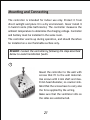
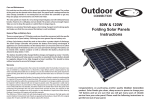
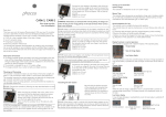
1
Mount the controller to the wall with
screws that fit to the wall material.
Use screws with 4 mm shaft and max.
8 mm head diameter, no counter sink.
Mind that the screws have to carry also
the force applied by the wiring.
Make sure that the ventilator slits on
the sides are unobstructed.
21
A DIN Rail mounting plate is available as an accessory (CX-DR2).
This allows mounting the controller on a standard 35mm DIN rail.
Remove the screws at the backside of the controller and screw
the mounting plate with the (long) fastening screw onto the
backside of the controller.
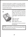
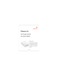
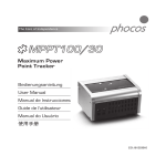
2
Connect the wires leading to the battery
with correct polarity. To avoid any
voltage on the wires, first connect the
controller, then the battery. Mind the
recommended wire length (min 30 cm
to max approx. 100 cm) and the wire
size:
CML05:
CML08:
CML10:
CML15,
min 2.5 mm2
min 4 mm2
min 6 mm2
CML20: min 10 mm2
Wrong polarity will cause a permanent
warning sound.
WARNING: If the battery is connected with reverse polarity,
the load terminals will also have the wrong polarity. Never
connect loads during this condition!
22
REMARK: Mind the recommendations of your battery
manufacturer. We strongly recommend connecting a fuse directly
to the battery to protect any short circuit at the battery wiring.
The fuse must take the charge controller nominal current:
CML05: 20A, CML08: 20A, CML10: 30A,
CML15: 30A, CML20: 40A
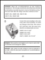
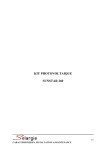
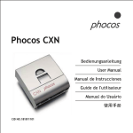
3
Connect the wires leading to the solar
array with correct polarity. To avoid
any voltage on the wires, first connect
the controller, then the solar array.
Mind the recommended wire size:
CML05:
CML08:
CML10:
CML15,
min 2.5 mm2
min 4 mm2
min 6 mm2
CML20: min 10 mm2
REMARK: Place positive and negative wire close to each other
to minimize electromagnetic effects.
REMARK: Solar panels provide voltage as soon as exposed to
sun light. Mind the solar panel manufacturer's recommendations
in any case.
23
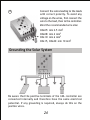
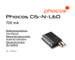
4
Connect the wires leading to the loads
with correct polarity. To avoid any
voltage on the wires, first connect the
wire to the load, then to the controller.
Mind the recommended wire size:
CML05:
CML08:
CML10:
CML15,
min 2.5 mm2
min 4 mm2
min 6 mm2
CML20: min 10 mm2
Grounding the Solar System
Be aware that the positive terminals of the CML controller are
connected internally and therefore have the same electrical
potential. If any grounding is required, always do this on the
positive wires.
24
REMARK: If the device is used in a vehicle which has the battery
negative on the chassis, loads connected to the regulator must
not have an electric connection to the car body. Otherwise the
Low Voltage Disconnect function and the electronic fuse function
of the controller are short circuited.
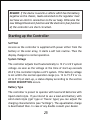
Starting up the Controller
Self Test
As soon as the controller is supplied with power either from the
battery or the solar array, it starts a self test routine. Then the
display changes to normal operation.
System Voltage
The controller adjusts itself automatically to 12 V or 24 V system
voltage. As soon as the voltage at the time of start-up exceeds
20.0 V, the controller implies a 24 V system. If the battery voltage
is not within the normal operation range (ca. 12 to 15.5 V or ca.
24 to 31 V) at start-up, a status display according to the section
ERROR DESCRIPTION occurs.
Battery Type
The controller is preset to operate with lead acid batteries with
liquid electrolyte. If you intend to use a lead-acid battery with
solid electrolyte ('gel' type or 'fleece' type) you can adjust the
charging characteristics (see "Settings"). The equalization charge
is deactivated then. In case of any doubts consult your dealer.
25
Recommendations for Use
The controller warms up during normal operation.
The controller does not need any maintenance or service. Remove
dust with a dry tissue.
It is important that the battery gets fully charged frequently (at
least monthly). Otherwise the battery will be permanently damaged.
A battery can only be fully charged if not too much energy is drawn
during charging. Keep that in mind, especially if you install
additional loads.
Display Functions in normal operation
The controller is equipped with 5 LEDs and an acoustic warning
signal.
Charge display
State of charge display
Load status display
26
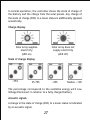
In normal operation, the controller shows the state of charge of
the battery and the charge from the solar panels. Any change of
the state of charge (SOC) to a lower status is additionally signaled
acoustically.
Charge display
Solar array supplies
electricity
(LED on)
Solar array does not
supply electricity
(LED off)
State of charge display
>75%
25-75%
<25%
flashes: <10%
The percentage corresponds to the available energy until Low
Voltage Disconnect in relation to a fully charged battery.
Acoustic signals
A change in the state of charge (SOC) to a lower status is indicated
by an acoustic signal.
27
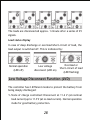
The loads are disconnected approx. 1 minute after a series of 25
signals.
Load status display
In case of deep discharge or overload/short-circuit of load, the
load output is switched off. This is indicated by:
Normal operation
(LED off)
Low voltage
disconnect (LED on)
Overload or
Short-circuit of load
(LED flashing)
Low Voltage Disconnect Function (LVD)
The controller has 2 different modes to protect the battery from
being deeply discharged:
1. State of charge controlled: Disconnect at 11.4 V (at nominal
load current) up to 11.9 V (at no load current). Normal operation
mode for good battery protection.
28
2. Voltage controlled: Disconnect at 11.0 V fixed setting. Appropriate
if bypass loads draw current directly from the battery.
The controller is preset to Mode 1 from the factory. Changing the
mode setting is described below.
In case of doubts which mode to choose, consult your dealer
because this has to be evaluated depending on the battery used.
Settings
The controller can be configured for special operation. For this
purpose, open the cover of the controller by removing the screws
on the back side.
WARNING: The controller should not be opened while connected
and in operation!
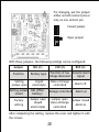
When the controller is opened, there are 3 jumpers on the electronic
board:
29
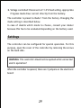
For changing, put the jumper
either on both contact pins or
only on one contact pin:
Closed jumper
Open jumper
With these jumpers, the following settings can be configured:
Jumper
GEL (1)
Function
Battery type
Setting
jumper open
Liquid
electrolyte
LVD (2)
BUZ (3)
Function of low Acoustic alarm
voltage disconnect
signal
State of charge
controlled
Alarm off
Setting jumper
closed
GEL (VRLA
battery)
Voltage controlled
Alarm on
Factory
setting
Jumper open
(liquid
electrolyte)
Jumper open
state-ofcharge
controlled
Jumper closed
Alarm on
After completing the setting, replace the cover and tighten it with
the screws.
30
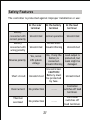
Safety Features
The controller is protected against improper installation or use:
At the solar
terminal
At the battery
terminal
At the load
terminal
Battery
connected with
correct polarity
Unrestricted
Normal operation
Unrestricted
Battery
connected with
wrong polarity
Unrestricted
Unrestricted.
Acoustic Warning
Unrestricted
Reverse polarity
Yes, not at
24V system
voltage
Yes, if only the
battery is
connected.
Acoustic Warning
Load output is
protected, but
loads might be
damaged.
Short circuit
Unrestricted
Unrestricted.
CAUTION:
Battery must
be protected
by fuse.
Unrestricted
Overcurrent
No protection
-------
Controller
switches off load
terminal.
Thermal
overload
No protection
-------
Controller
switches off
load terminal.
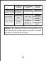
31
At the solar
terminal
At the battery
terminal
At the load
terminal
No connection
Unrestricted
Unrestricted
Unrestricted
Reverse current
Unrestricted
Overvoltage
Varistor 56 V,
2.3 J
Undervoltage
Normal
operation
-------
Max. 40 V
-------
Controller
switches off load
terminal.
Controller
Controller
switches off switches off load
load terminal.
terminal.
WARNING: The combination of different error conditions may
cause damage to the controller. Always remove the error before
you continue connecting the controller!
32
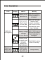
Error Description
Error
Display
Reason
Remedy
Load will reconnect
Battery is low
as soon as battery is
(Red LED on)
recharged.
Overcurrent/
Short circuit
of loads (Red
LED flashing)
Loads are
not supplied
Switch off all loads.
Remove short
circuit. Controller
will switch on load
automatically after
max 1 minute.
Check if other sources
Battery voltage
overcharge the battery.
too high
If not, controller is
(>15.5 / 31.0 V)
damaged.
Battery wires
or battery fuse Check battery wires,
damaged,
fuses and battery.
battery has
high resistance
Battery is
empty after
a short time
Battery has
low capacity
(Red LED on)
33
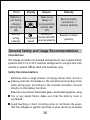
Change battery
Error
Display
Battery is
not being
charged
during the
day
Battery
wrong
polarity
Reason
Solar array
faulty or
wrong polarity
(Green LED
off)
Battery is
Permanent connected with
reverse polarity
sound
Remedy
Remove faulty
connection /
reverse polarity
Remove reverse
polarity
General Safety and Usage Recommendations
Intended Use
The charge controller is intended exclusively for use in photovoltaic
systems with 12 V or 24 V nominal voltage and in conjunction with
vented or sealed (VRLA) lead acid batteries only.
Safety Recommendations
Batteries store a large amount of energy. Never short circuit a
battery under all circumstances. We recommend connecting a fuse
(slow acting type, according to the nominal controller current)
directly to the battery terminal.
Batteries can produce flammable gases. Avoid making sparks, using
fire or any naked flame. Make sure that the battery room is
ventilated.
Avoid touching or short circuiting wires or terminals. Be aware
that the voltages on specific terminals or wires can be up to double
34
the battery voltage. Use isolated tools, stand on dry ground and
keep your hands dry.
Keep children away from batteries and the charge controller.
Please observe the safety recommendations of the battery
manufacturer. If in doubt, consult your dealer or installer.
Liability Exclusion
The manufacturer shall not be liable for damages, especially on
the battery, caused by use other than as intended or as mentioned
in this manual or if the recommendations of the battery manufacturer
are neglected. The manufacturer shall not be liable if there has
been service or repair carried out by any unauthorized person,
unusual use, wrong installation, or bad system design.
35
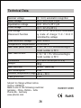
Technical Data
12 / 24 V, automatic recognition
14.5 / 29.0 V (25°C),2h
14.8 / 29.6 V (25°C),2h
13.7 / 27.4 V (25°C)
11.4 - 11.9 / 22.8-23.8 V controlled
by state of charge 11.0 / 22.0 V
controlled by voltage
Load reconnect voltage
12.8 / 25.6 V
Temperature compensation -4 mV/cell*K
Max. solar panel current
5 / 8 / 10 / 15 / 20 A according to
model number @ 50°C
Max. load current
5 / 8 / 10 / 15 / 20 A according to
model number @ 50°C
Dimensions
80 x 100 x 32 mm (w x h x d)
Weight
180gr
Max. wire size
16 mm2 (AWG #6)
Self consumption
4 mA
Ambient temperature range -40 to + 50°C
Case protection
IP 22
Nominal voltage
Boost voltage
Equalization voltage
Float voltage
Low Voltage
Disconnect Function
Subject to change without notice.
Version: 20090103
Made in one of the following countries:
Germany - China - Bolivia - India
Phocos AG - Germany
www.phocos.com
36
ISO9001:2000
RoHS