1
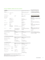
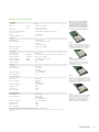
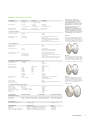
ETSI Datasheet
Eclipse TM
Powers Wireless Backhaul Networks
Eclipse combines all PDH, SDH and Ethernet
point-to-point wireless applications into
a single product platform to dramatically
reduce the total cost of using wireless
backhaul, and change the way networks
are planned, deployed and maintained.
Eclipse is the leading wireless backhaul solution
available, combining a number of compelling features:
Software DeFIned
A highly scalable, software-driven architecture gives operators total control
over their networks, so they can adapt to changing conditions and anticipate
future needs.
Optimized Wireless Nodes
The Eclipse nodal solution supports multiple outdoor units (ODUs) with
built-in traffic routing, add-and-drop, aggregation and concentration, and
selectable traffic interfaces, including E1, E3, STM1 and 10/100 Base-T
and Gigabit Ethernet.
Efficient Terminal Options
Eclipse supports a number of simple, application-specific Indoor Units to provide
cost-efficient terminal solutions for the transport of E1, STM1 and Ethernet data.
Scalable Capacity Architecture
Only pay for the capacity you need today. Super-PDHTM capacity migration
enables smooth network upgrades and expansion at minimal cost and
service disruption.
High-Speed Data Transport
Eclipse ‘Liquid Bandwidth’ supports hybrid high-speed native Ethernet/IP plus
TDM traffic over a single radio channel, configurable bandwidth assignment up
to 360 Mbps with low latency, built-in Layer 2 operation, service differentiation
and Carrier-Grade QoS features.
Control and Intelligence
The Eclipse software suite enables advanced network control and intelligence
through a suite of Java-based Local and Network Management tools.
Datasheet
ECLIPSE ETSI
System Parameters
Eclipse has it covered, whatever
your wireless application.
• 5 to 38 GHz,
• PDH, SDH and Ethernet,
• QPSK to 256 QAM,
• 4x E1 to 4x STM1,
• 10 - 360 Mbit/s Ethernet.
An array of flexible configuration
choices, including optional
diversity and XPIC co-channel
support.
Secure and reliable operation
in licensed frequency bands,
with full compliance to
applicable FCC, SRSP, NTIA
and ITU Standards.
Eclipse designs are hardened
for maximum survivability,
in any and all installation
environments.
Accelerated lifetime testing
ensures reliable operation
over the full 15 year equipment
lifetime.
Java-based Portal local
management software and
ProVision Element Management
system, are specifically designed
to provide exceptional control for
Eclipse wireless nodal networks.
01. General
Operating Frequency Range
5 to 38 GHz
2.048 Mbit/s (E1)
34.368 Mbit/s (E3)
155.52 Mbit/s (STM1)
4x, 5x, 8x, 10x, 16x, 20x, 32x, 40x, 48x, 52x, 64x, 75x, 93x, 100x E1
1x, 2x, 4x STM1
10-360 Mbit/s Ethernet
QPSK, 16, 32, 64, 128, 256 QAM
FEC, Reed Solomon Decoding
24 tap T/2 Equalizer
Digital Line Rate
Capacity Range Options
Modulation Options - Fixed or Adaptive
Error Correction
Adaptive Equalization (Except for IDUsp and IDUspe)
02. Radio Path Protection Options
Non Protected, 1+0
Protected Hot Standby, 1+1
Space Diversity, 1+1
Ring protection (Super PDH)
Frequency Diversity, 1+1 [1]
Dual Path, Non-Protected, 2+0
Dual Path, Protected, 2+2
XPIC Optional
XPIC Optional
5 to 38 GHz
5 to 38 GHz
5 to 38 GHz
5 to 38 GHz
5 to 38 GHz
5 to 38 GHz
5 to 38 GHz
INU/INUe
IDU
ODUs
INU/INUe/IDU
EN 301 489-1, EN 301 489-4 (EN 55022 Class A)
EN 301 489-1, EN 301 489-4 (EN 55022 Class B)
ETS 300 019, Class 4.1
ETS 300 019, Class 3.1E
ETS 300 019, Class 1.2
ETS 300 019, Class 2.3
IEC 60950-1/EN 60950-1
EN 302 217-2-2
IEC 60529 (IPX6)
IEC 61000-4-5 Class 5, GR-1089-CORE 4.11 Type 1, 3, 5 & 6
03. Standards Compliance
EMC
Operation
Operation
Storage
Transportation
Safety
Radio Frequency
Water Ingress
Lightning Protection
ODU
ODU
04. Environmental
Operating Temperature
INU/INUe/IDU
INU/INUe/IDU
ODU
ODU
Guaranteed
Extended [2]
Guaranteed
Extended [2]
-5° to +45° C (23° to +113° F)
-5° to +55° C (23° to +131° F)
-33° to +55° C (-27° to +131° F)
-50° to +65° C (-58° to +149° F)
Humidity
INU/INUe/IDU
ODU
Guaranteed
Guaranteed
0 to 93%, non-condensing
0 to 100%
Guaranteed
4,500 Meters (15,000 ft)
Altitude
05. Fault and Configuration Management
Protocol
Interface, Electrical
Interface, Physical
Local/Remote Configuration and Support Tool
Performance Monitoring
Routing Protocols Supported
Network Management
Engineering Orderwire
SNMP v2
Ethernet 10/100 Base-T or RS232
RJ-45
Eclipse Portal
To ITU-T Rec. G.826
Static and Dynamic Routing, RIP I, RIP II, OSPF
Aviat Networks ProVision® or NetBoss®
Via Optional VoIP Handset or External RS-422 Digital Orderwire Unit (eg: Ardax)
06. Emission Designator
Bandwidth
Emission Designator
Eclipse standard features
include adaptive equalization,
and forward error correction
with interleaving, for superior
performance in the most
demanding propagation
conditions.
QPSK
QAM
3.5MHz
7MHz
13.75MHz
14MHz
27.5MHz
28MHz
55MHz
56MHz
3M50G7W
3M50D7W
7M00G7W
7M00D7W
13M75G7W
13M75D7W
14M0G7W
14M0D7W
27M5G7W
27M5D7W
28M0G7W
28M0D7W
N/A
55M0D7W
N/A
56M0D7W
07. Dispersive Fade Margin (DFM)
Capacit y/Modul ation
Gross Bit Rate Mbit/s [3]
Modul ation Options
Symbol Rate Mbaud
DFM (dB)
4xE1
5xE1, 10Mbit/s
8xE1
10xE1, 20Mbit/s
16xE1, 30 Mbit/s
20xE1, 40Mbit/s
27xE1, 50 Mbit/s
32xE1, 50 Mbit/s
40xE1, 80Mbit/s
52xE1, 100Mbit/s
64xE1
75xE1, 150Mbit/s
1xSTM1, 150Mbit/s
93xE1, 200Mbit/s
100xE1, 200Mbit/s
200Mbit/s
250 Mbit/s
2xSTM1, 310Mbit/s
360 Mbit/s
9.4
11.5
18.8
22.8
37.6
44.9
61.3
71.2
88.9
116.6
142.4
167.8
167.0
208.8
229.4
250.8
280.0
334.0
384.0
QPSK
QPSK / 16 QAM
QPSK
QPSK / 16 QAM
QPSK / 64 QAM
QPSK / 16 QAM
32 QAM
16 QAM / 64 QAM
16 QAM
32 QAM
64 QAM
16 QAM / 128 QAM
16 QAM / 64 QAM / 128 QAM
256 QAM
32 QAM / 128 QAM
64 QAM
64 QAM
128 QAM / 256 QAM
256 QAM
4.85
5.79 / 2.9
9.35
11.63 / 5.81
18.31 / 5.90
22.94 / 11.47
11.95
18.15/ 12.00
22.69
23.72
23.82
41.76 / 24.48
41.62 / 30.53 / 24.39
26.10
45.88 / 32.77
41.78
46.0
47.58 / 43.82
47.82
74.5
75 / 78
71.5
72 / 75
68.5 / 67
68 / 59
59
64 / 64
66
54
51
52 / 49
52 / 52 / 49
46
51 / 50
45
45
42 / 40
40
All specifications are typical values unless otherwise stated, and are subject to change without notice.
[1] Frequency Diversity is supported by the INU/INUe only, for capacities of 10xE1 and above.
[2] Over full Extended Operating Temperature Eclipse may be subject to reduced performance. Contact Aviat Networks for more details.
[3] Gross bit rate includes usable customer payload plus radio overhead for FEC, NMS, AUX traffic, etc.
2
AVIAT NETWORKS
Eclipse Terminal, Indoor Unit (IDU) Options
01. General
Configuration Memory,
Removable [1][2]
Up to 128 Mbyte CompactFlash Card (Rear
Access)
LED Indicators
Line Interface, E1 Electrical
2x Tri-state LEDs (‘IDU Status’, ‘ODU Status’)
Standards Compliance
Line Code
Impedance
Compliant to ITU-T Rec. G.703, G.823
HDB3
75Ω unbalanced or 120Ω balanced, configurable
IF Cable Connector
N-Type
IF Interface Parameters
Transmit
Receive
Protection Connector
(Where Available)
Auxiliary Data
Eclipse Indoor Units provide a simple
and economical solution for terminal
configurations, where support for only
one radio path is required. IDU options
are available for software configurable
transport of E1, STM1 and Ethernet traffic.
311 MHz, -8 to -12 dBm
126 MHz, -8 to -27 dBm
9 pin D-SUB
IDUsp 4x & 16x
Aux Data Channels
Interface
Line Rate, Configurable
Connector Type
1
RS232 or RS422
1.2 to 19.2 kbit/s, Asynchronous
64 kbit/s, Synchronous
9 pin D-SUB
Provides lowest-cost termination of standard
PDH link capacities of 4, 8 and 16x E1 using
QPSK modulation.
Alarm I/O [2]
External Alarm Inputs
External Alarm Outputs
Connector Type
2x TTL
4 x Form C Relay
15 pin D-SUB
IDU 20x
NMS LAN Interface
Type
Connector
10/100baseT Ethernet
8-pin RJ45
Serial Maintenance
Interface [2]
Standard
Speed
Connector
Complies to TIA/EIA-561
1.2 to 115.2 kbit/s
8-pin RJ45
Electrical
Input Voltage Range
Power Consumption
Protection Circuit
IDUsp 4x, IDUsp 16x
IDU 20x, IDU 155o, IDU ES, IDU GE 20x
Dimensions
Weight
IDUsp 4x, IDUsp 16x, IDU GE 20x
IDU 20x, IDU 155o, IDU ES
IDUsp 4x, IDUsp 16x, IDU GE 20x
IDU 20x, IDU 155o, IDU ES
[1]
Mechanical
-40.5 to -60.0 VDC
8W
12 W
5A Slow-Blow Fuse
44mm (1RU)x 482mm (19in) x 240mm (9.4in)
44mm (1RU)x 482mm (19in) x 277mm (10.9in)
1.1 kg (2.5 lb)
1.6 kg (3.5 lb)
Supports software scalable, enhanced
PDH link capacities between 5 and 40x E1.
IDU 155o
SDH IDU that enables transport of a single
STM1 channel using selectable 16, 64 or
128QAM modulation.
IDU ES
Combines 4x 10/100 baseT Ethernet traffic
and up to 8xE1 wayside channels, with
programmable aggregate link speeds up
to 200 Mbit/s.
IDU GE 20x
02. IDU Standard Performance (SP) Options
IDUsp 4x
IDUsp 16x
Capacity Options (Configurable)
4x 2.048 Mbit/s (E1)
4, 8, 16x 2.048 Mbit/s (E1)
Modulation
QPSK
QPSK
Traffic Connectors
4x RJ45
16x RJ45
Configuration Options
Non Protected (1+0) Only
Non Protected (1+0)
Protected Hot Standby (1+1) [3]
Combines 3x Gigabit Ethernet ports (two
electrical and one optical) with up to 20xE1
TDM channels, and programmable aggregate
link speeds up to 360 Mbit/s.
03. IDU Super-PDH and SDH Options
IDU 20x
IDU 155o
Capacity Options (Configurable)
5, 10, 20, 40x 2.048 Mbit/s (E1)
1x 155.52 Mbit/s (STM1)
Modulation Options (Configurable)
QPSK, 16 to 64 QAM
16, 64, 128 QAM
Traffic Connectors
20x RJ45
SC [4]
Configuration Options
Non Protected (1+0)
Protected Hot Standby (1+1)
Protected Space Diversity (1+1)
Non Protected (1+0)
Protected Hot Standby (1+1)
Protected Space Diversity (1+1)
04. IDU Ethernet Options
IDU ES
IDU GE 20x
Capacity Options (Configurable
by Downloadable License)
10, 20, 30, 40, 50, 80, 100, 150, 200
Mbit/s
10, 20, 30, 40, 50, 80, 100, 150, 200,
250, 310, 360 Mbit/s
Modulation Options (Configurable)
QPSK, 16, 32, 64, 128,
256 QAM
QPSK, 16, 32, 64, 128, 256 QAM
4x 10/100 baseT
4x 8-pin RJ45
2x 10/100/1000 baseT
2x 8-pin RJ45
Ethernet Traffic Interface, Electrical
Interfaces
Connectors
Ethernet Traffic Interface, Optical
(Optional)
Interfaces
Connectors
Frame Sizes Supported
Wayside Traffic Channels
Configuration Options
1x Optical IEEE 802.3z 1000 BASE-LX
1x LC (SFP) [5]
64 to 1536 bytes
64 to 9600 bytes [6]
Interfaces
8x 2.048 Mbit/s (E1)
20x 2.048 Mbit/s (E1)
Connectors
8x RJ45
20x RJ45
Non Protected (1+0)
Non Protected (1+0)
Protected Hot Standby (1+1)
Protected Space Diversity (1+1)
All specifications are typical values unless otherwise stated, and are subject to change without notice.
[1] AUX channel not supported by IDU GE 20x. IDUsp 4x/16x supports 64kbps synchronous only.
[2] Not available for IDUsp 4x/16x.
[3] IDU 1+1 protection does not support hitless switching or diversity configurations.
[4] For IDU 155o optical interface specifications refer to the Optical Interface Parameters under Transparent DAC Options.
[5] For IDU GE 20x optical interface specifications refer to the DAC GE Optical Interface Parameters.
[6] 64 to 7000 bytes bidirectional, 7000+ to 9600 bytes unidirectional.
AVIAT NETWORKS
3
Datasheet
ECLIPSE ETSI
Eclipse Node, Intelligent Node Unit (INU) Common Units
The Eclipse Intelligent Node Unit
(INU) and Extended INU (INUe)
provide optimized wireless nodal
networking, supporting multiple
radio paths from a single unit.
Each node consists of a standard
Chassis equipped with common
cards listed below. Additional
hot-swappable Radio (RAC) and
Data Access (DAC) Cards are
added to provide required node
functionality.
01. IDC, Indoor Chassis 1RU
Dedicated Plug-in Card Slots
Universal Plug-in Card Slots
Maximum Number of ODUs Supported
Dimensions (Including Mounting Brackets)
Weight
Empty
2 (NCC, FAN)
4
3
44mm (1RU) x 482mm (19in) x 282.5mm (11.1in)
2.6 kg (5.8 lb)
Empty
3 (NCC, NPC, 1x2RU FAN or 2x 1RU FAN)
9
6
88mm (2RU) x 482mm (19in) x 282.5mm (11.1in)
4.8 kg (10.6 lb)
02. IDCe, Extended Indoor Chassis 2RU
Dedicated Plug-in Card Slots
Universal Plug-in Card Slots
Maximum Number of ODUs Supported
Dimensions (Including Mounting Brackets)
Weight
03. NCC, Node Controller Card
NMS LAN interface
Serial Maintenance Interface
Node Controller Card (NCC)
Provides node management and
control, primary DC power, and
interfaces for Portal and NMS. A
removable Compact Flash card
holds configuration data and
software License.
Configuration Memory, Removable
Electrical
Power consumption (Including DC/DC Efficiency)
LED Indicators
Dimensions (Including Front Panel and Rear Connector)
Weight
Type
Connector
Standard
Speed
Connector
DC Supply Input Range
DC Fuse Type and Rating
Over Voltage Protection
Under Voltage Protection
DC Connector
4-port 10/100baseT Hub
4x 8-pin RJ45
Complies to TIA/EIA-561
1200 bit/s to 115.2 kbit/s
8-pin RJ45
Up to 128 Mbyte CompactFlash Card (On-board)
-40.5 to -60 VDC
25A Fast-acting Ceramic Body Cartridge
< -70 VDC
-32 VDC
2-pin DSUB Power Type
<4W
2x Tri-state (‘Test’, ‘Status’)
22mm (0.5RU) x 260mm (10.2in) x 268mm (10.6in)
0.6 kg (1.35 lb)
04. NPC, Node Protection Card
Node Protection Card (NPC)
Provides redundancy for the
NCC control and DC power
supply functions for higher
reliability nodes.
Electrical
Power Consumption (Including DC/DC Efficiency)
LED Indicators
Dimensions (Including Front Panel and Rear Connector)
Weight
2
1x Red LED (‘Fault’)
<2W
44mm (1RU) x 40mm (1.6in) x 264mm (10.4in)
0.23 kg (0.5 lb)
06. FAN, Fan Card 2RU
Fans
LED Indicators
Power Consumption
Dimensions (Including Front Panel and Rear Connector)
Weight
2
1x Red LED (‘Fault’)
<4W
88mm (2RU) x 40mm (1.6in) x 264mm (10.4in)
0.46 kg (1.0 lb)
07. AUX, Auxil ary Services Card
Aux Data Channels
Interface
Line Rate
Aux Data Connector
External Alarm Inputs
Auxiliary Services Card (AUX)
The AUX card provides user
configurable auxiliary data
channels and alarm input/output
(I/O) options. One or more AUX
cards can be fitted to a node.
-40.5 to -60 VDC
25A Fast-acting Ceramic Body Cartridge
< -70 VDC
-32 VDC
2-pin DSUB Power Type
<4W
2x Tri-state (‘Protect’, ‘Status’)
22mm (0.5RU) x 130mm (5.1in) x 268mm (10.6in)
0.4 kg (0.88 lb)
05. FAN, Fan Card 1RU
Fans
LED Indicators
Power Consumption
Dimensions (Including Front Panel and Rear Connector)
Weight
Fan Card (FAN)
The FAN module includes two
long-life axial fans to provide
forced air cooling. The FAN card
comes in two sizes – One 1RU
FAN is fitted in the INU; one
2RU FAN is fitted in the INUe.
DC Supply Input Range
DC Fuse Type and Rating
Over Voltage Protection
Under Voltage Protection
DC Connector Type
External Alarm Outputs
Alarms Connector
LED Indicators
Power Consumption
Dimensions (Including Front Panel and Rear Connector)
Weight
Asynchronous
Synchronous
TTL Inputs
TTL Input Thresholds
External Alarm Outputs
3
RS232 or RS422
1.2 to 19.2 kbit/s
64 kbit/s
High Density DSUB26
Up to 6 [1]
0.8V min low, 2.0V min high
Up to 4 [1]
High Density DSUB15
1x Tri-state (‘Status’)
<3W
22mm (0.5RU) x 130mm (5.1in) x 268mm (10.6in)
0.35 kg (0.77 lb)
All specifications are typical values unless otherwise stated, and are subject to change without notice.
[1] For applications requiring additional alarm inputs or outputs, multiple AUX cards can be installed if free INU/INUe slots are available.
4
AVIAT NETWORKS
Radio Access Cards (RAC)
01. General
IF Connector
IF Interface
SMA [1]
Transmit
311 MHz, -8.0 to -12.0 dBm
Receive
126 MHz, -8 to -27 dBm
LED Indicators
2x Tri-state (‘Online’, ‘Status’)
Dimensions (Including Front Panel
and Rear Connector)
22mm (0.5RU) x 130mm (5.1in) x 268mm (10.6in)
Weight
< 0.38 kg (0.84 lb)
Secondary Lightning Protection
Gas tube, 150 V
RACs provide the conversion of TDM and
Ethernet traffic for interfacing between
the node and an ODU. Functions include
modulation/demodulation, FEC, adaptive
equalization, IF conversion, IF loopback
and automatic protection switching for hot
standby, diversity and ring configurations.
02. RAC 30
ODUs Supported
ODU300sp, hp, ep
Capacities Supported
5, 10, 16, 20, 32, 40, 52, 64, 75x E1,
1x STM1,
10 - 150 Mbit/s Ethernet
Modulations Supported
QPSK, 16, 32, 64, 128QAM
Power Consumption
7W
RAC 30
Supports software configurable capacities up
to 75x E1 or 1x STM1, modulations from QPSK
to 128 QAM and bandwidths up to 30 MHz.
Compatible with all ODU300 types (sp/hp/ep).
03. RAC 30a
ODUs Supported
ODU300sp, hp
Capacities supported
Non-AM mode
5, 10, 16, 20, 32, 40, 52, 64, 75x E1, 1x STM1, 10 - 130 Mbit/s Ethernet
Modulations supported
Non-AM mode
QPSK, 16, 32, 64, 128QAM [2]
Capacities supported
AM mode
10 - 130 Mbit/s (Nx E1 + Ethernet)
Modulations supported
AM mode
QPSK, 16, 64QAM [2]
Power consumption
8W
04. RAC 3X
ODUs Supported
ODU300hp, ep
Capacities Supported
75, 93, 100x E1,
1-2x STM1,
150 - 310 Mbit/s Ethernet
Modulations Supported
16, 64, 128, 256QAM
Power Consumption
11 W
RAC 3X
Supports capacity options requiring
channel bandwidths greater than
30 MHz, with modulations up to 256 QAM,
including higher capacities up to 2x STM1.
Compatible ODU300hp/ep.
RAC 40
05. RAC 40 with XPIC
ODUs Supported
ODU300hp, ep
Capacities Supported
52, 64, 75x E1,
1x STM1,
150 Mbit/s Ethernet
Modulations Supported
32, 64, 128QAM [2]
XPD Improvement
20 dB
XPIC Connectors
2x SMB
Power Consumption
14 W
06. RAC 4X with XPIC
ODUs Supported
ODU300hp, ep
Capacities Supported
75, 93, 100x E1,
1x STM1, 2xSTM1,
150 - 310 Mbit/s Ethernet
Modulations Supported
16, 32, 64, 128, 256QAM [2]
XPD Improvement
20 dB
XPIC Connectors
2x SMB
Power Consumption
14 W
Provides co-channel operation with cross-pole
interference cancellation (XPIC), for selected
capacity options with bandwidths up to 30 MHz
and modulations to 128 QAM. Compatible with
all ODU300 types (hp/ep).
RAC 4x
Combines the functions of the RAC 3X and RAC
40 cards, by providing co-channel operation
with cross-pole interference cancellation
(XPIC), for selected capacity options with
bandwidths up to 56 MHz and modulations to
256 QAM. Compatible with ODU300hp/ep.
All specifications are typical values unless otherwise stated, and are subject to change without notice.
[1] RAC Installation Kit includes 3 meter jumper cable, SMA to N-type.
[2] Not all possible combinations of capacities and modulations are supported. Please refer to the Eclipse User Manual or System Description for
full details.
AVIAT NETWORKS
5
Datasheet
ECLIPSE ETSI
Data Access Cards (DAC)
DACs provide customer traffic
access for full termination of
payload traffic or partial add
and drop node configurations.
DACs provide direct transparent
mapping or optional multiplexing
of TDM or Ethernet data from the
INU backplane, and are independent of link or node capacity.
01. General
LED Indicators
1x Tri-state (‘Status’)
Power Consumption (Nominal)
<3W
Dimensions (Including Front Panel and Rear Connector)
22mm (0.5RU) x 130mm (5.1in) x 268mm (10.6in)
Weight (Nominal)
< 0.34 kg (0.74 lb)
02. Transparent DAC Options
Interface, Configurable
DAC 4x
DAC 16x
DAC 3xE3M
DAC 155o
DAC 2x155o
DAC 2x155e
Electrical
Electrical
Electrical
Optical
Optical
Electrical
1 to 4x 2.048 Mbit/s (E1)
1 to 16x 2.048 Mbit/s (E1)
1 to 2x 34.368 Mbit/s (E3)
1x 155.52 Mbit/s (STM1)
1 or 2x 155.52 Mbit/s (STM1)
1 or 2x 155.52 Mbit/s (STM1)
Electrical Interface Parameters
Standards Compliance
E1, E3
STM1
E1, E3
STM1
DAC 4x
DAC 16x
DAC 3xE3M
DAC 2x155e
E1
E3, STM1
Compliant to ITU-T Rec. G.703, G.823
Compliant to ITU-T Rec. G.703, G.825
HDB3
CMI
RJ45
48 Pin Mini-RJ21
Slimline BNC
BNC
75Ω unbalanced or 120Ω balanced, configurable
75Ω Unbalanced
STM1
Compliant to ITU-T Rec. G.957, G.825
Short Range S-1.1
SC
1261 to 1310 nm
-15 to -8 dBm
1100 to 1600 nm
-34 dBm
-7 dBm
DAC NxE1
DAC options provide either 4x E1
or 16x E1 interfaces per card.
Line code
Connectors
Impedance
Optical Interface Parameters
DAC 3xE3M
A configurable multi-function
DAC, providing three transparent
E3 interfaces, two E13 interfaces
(multiplexing 16xE1 to 1xE3 on the
front interface), or two E3 channels
for video/ATM applications (E3 carried over concatenated 17xE1) per
card. 1+1 hot-standby protectable.
Standards Compliance
Optical Interface
Connectors
Tx Output Center Wavelength, λc
Tx Average Optical Output Power, Po
Rx Input Operating Center Wavelength, λc
Rx Sensitivity, Pin
Rx Input Power Saturation, Pin
03. SDH Multiplexer DAC Options
DAC 155oM
Interface
1x 155.52 Mbit/s (STM1)
Optical
Functionality
Optical Interface Type
(Hot-Swappable SFP)
DAC NxSTM1
SDH DAC options provide one or
two optical 155 Mbps interfaces, or
two 155 Mbps electrical interfaces.
Optical Interface Parameters
1x STM1 (Interface) to 63x E1 (TDM Bus) Mux
Standard
Long Range L1.1
Optional
Connectors
Intermediate Range (IR)
LC
Tx Output Center Wavelength λc
Tx Average Optical Output Power, Po
Rx Input Operating Center Wavelength, λc
Rx Sensitivity, Pin
Rx Input Power Saturation, Pin
Maximum Range (Nominal)
Short Range S1.1
1261 to 1360 nm
-15 to -8 dBm
1260 to 1600 nm
-34 dBm
0 dBm
15 km
Timing Modes, Configurable
DAC 1x155oM
SDH Multiplexer DAC which
maps up to 63x E1 circuits to/
from the INU TDM Bus to an STM1
optical customer interface. 1+1 hotstandby protectable.
DAC ES
Provides 4x 100 Base-T
Fast Ethernet interfaces, with
configurable aggregate throughput
capacity from 6 to 152 Mbps.
Loop Time (Clock Recovered from Received STM1)
Local Reference Clock (XO)
04. Ethernet DAC Options
DAC ES
Transport Channels
2
2
Throughput Capacity,
Per Channel
2 to 98 Mbit/s, 2
Mbit/s Increments
2 to 200 Mbit/s, 2 Mbit/s Increments
155 or 311 Mbps
Interfaces
4x 10/100 baseT
3x 10/100/1000 baseT
Connectors
4x 8-pin RJ45
3x 8-pin RJ45
Ethernet Traffic Interface, Optical
Interfaces
Connectors
1x Optical IEEE 802.3z 1000 BASE-LX
1x LC (SFP)
Optical interface Parameters
Tx Output Center Wavelength, λc
1270 to 1355 nm
Tx Average Optical Output Power, Po
-9.5 to -3 dBm
Rx Input Operating Center Wavelength, λc
1260 to 1610 nm
Rx Sensitivity, Pin
-20 dBm
-3 dBm
LED Indicators
1x Tri-state (‘Status’)
1x Tri-state (‘Status’)
Frame Size Supported
64 to 1536 Bytes
64 to 9600 Bytes [1]
[1] 64 to 7000 bytes bidirectional, 7000+ to 9600 bytes unidirectional.
6
AVIAT NETWORKS
DAC GE
Electrical Traffic Interface,
Electrical
Rx Input Power Saturation, Pin
DAC GE
Provides 3x 1000 Base-T and one
optical IEEE 802.3z 1000 Base-LX
Gigabit Ethernet interfaces, with
configurable aggregate throughput
capacity up to 360 Mbps.
Long Range L1.1
1260 to 1355 nm
-5 to 0 dBm
1260 to 1600 nm
-35 dBm
0 dBm
40 km
General ODU Specifications
01. General
ODU300 sp
ODU300 hp
ODU300 ep
Frequency Band Options
7, 8, 11, 13, 15, 18, 23,
32, 38 GHz
L6, U6, 7, 8, 10, 11, 13, 15,
18, 23, 26, 28, 32, 38 GHz
5, 13, 15 GHz
Capacity Support
4 to 40x E1
5 to 100x E1
1 to 2x STM1
10 - 360 Mbit/s Ethernet
QPSK to 256 QAM
10 - 80 Mbit/s Ethernet
5 to 100x E1
1 to 2x STM1
4-360 Mbit/s Ethernet
Modulation Support
QPSK, 16 QAM
QPSK to 256 QAM
Lightning Protection
ODU300hp: standard internal; ODU300sp/ep: optional external
Eclipse ODUs are compact, fully
environmentally sealed units that are
entirely independent of link capacity,
payload and modulation, which can all
be set completely under software control.
Wideband diplexers also provide a wide
tuning range via software to increase
flexibility and minimize sparing.
ODU options are available with differing
maximum capacity and RF performance
specifications. All ODUs are designed to
mount directly to the antenna, and connect
to the INU/IDU by a single coaxial cable.
02. IF Specifications
Intermediate Frequency
Transmit
Receive
311 MHz
126 MHz
INU/IDU to ODU IF Cable,
Recommended
CNT-300 Type
CNT-400 Type
0.3 Inch/Copper Braid/Solid Copper Centre
Conductor, 50Ω
Maximum IF Cable Length 150 Meters (500 ft)
0.4 Inch/Copper Braid/Copper Clad Aluminum
Centre Conductor, 50Ω
Maximum IF Cable Length 300 Meters (1,000 ft)
ODU300sp
Delivers Standard Performance operation
with both QPSK and 16QAM modulation
and scalable capacity up to 40xE1 for TDM
transport, or 80 Mbit/s of Ethernet data, in
licensed frequency bands from 7 to 38 GHz.
03. ODU Interfaces
IF Cable Connector
N-Type
AGC Monitor Point
Antenna Port Interface
BNC
5 GHz
6-38 GHz
Coax, 7/16 DIN F
Standard EIA Rectangular Waveguide,
Refer to ODU System Specifications
Polarisation, Field Selectable
Antenna Mounting
Vertical (Standard) or Horizontal
5 GHz, Standard
6-38 GHz, Standard
6-38 GHz, Optional
Remote Mount Via Coax Connection
Proprietary Direct Mount for Antenna Diameters 0.3
to 1.8m (1 to 6ft)
Remote Mount for Antenna Diameters >1.8m (>6ft)
Remote Mount Via Flex/Elliptical Waveguide
04. General Transmitter Specifications
Transmit Power Tolerance
Transmitter Source
5 to 26 GHz
28 to 38 GHz
± 2 dB
± 3 dB
Synthesized
± 10 ppm
Frequency Stability
Manual Transmitter
Power Control Range
Automatic Transmitter
Power Control
ODU300 sp, hp
20 dB
18 dB
17.5 dB
17 dB
16 dB
14 dB
QPSK
16QAM
32QAM
64QAM
128QAM
256QAM
Resolution
Accuracy
Range
Resolution/Speed
Transmitter Mute
Channel Selection
Synthesizer Resolution
ODU300ep (5 GHz)
30 dB
26 dB
25.5 dB
25 dB
24 dB
22 dB
0.1 dB Steps
± 2 dB
Configurable Over Full Available Manual
Attenuation Range
0.1 dB Steps/6 dB Per Second
> 50 dB
By Software Control Within Tuning Range of ODU
0.25 MHz
ODU300hp
Delivers High Performance operation with
QPSK to 256QAM modulation and scalable
capacity up to 100xE1 or 2xSTM1 for TDM
transport, or 360 Mbit/s of Ethernet data, in
licensed frequency bands from 6 to 38 GHz.
ODU300ep
Delivers Extended Performance operation
with QPSK to 256QAM modulation and
scalable capacity up to 75xE1 or 2xSTM1
for TDM transport, or 360 Mbit/s of Ethernet
data, in the 5, 13 and 15 GHz licensed
frequency bands.
05. General Receiver Specifications
Receiver Source
Frequency Stability
Receiver Overload
Residual (Background) Bit
Error Rate
RSSI Accuracy [1]
BER = 1x10 -6
BER = 1x10 -3
-40 to -70 dBm, 0 to +35oC
-25 to -85 dBm, -33 to +55oC
06. Additional
Protection Losses
Frequency Band
Main Channel
Protection Channel
Splitter Option
Coupler Option
5 GHz / 6 to 18 GHz / 21 to 32 GHz / 38 GHz
5 GHz / 6 to 18 GHz / 21 to 32 GHz / 38 GHz
3.5 dB / 3.6 dB / 3.8 dB / 4 dB
1.5 dB / 1.6 dB / 1.8 dB / 2 dB
3.5 dB / 3.6 dB / 3.8 dB / 4 dB
6.4 dB / 6.6 dB / 6.8 dB / 7 dB
Synthesized
± 10 ppm
-22 dBm
-20 dBm
Better than 10 -13
± 2 dB
± 4 dB
07. Electrical
Power Consumption, Nominal
ODU300sp / hp / ep
20 W / 30 W / 40 W
08. Mechanical
Size (Hx W xD)
Weight
ODU300sp, hp
ODU300ep
ODU Protection Splitter/Coupler (RW)
ODU Protection Splitter/Coupler (P)
287mm (11.3 in) x 287mm (11.3 in) x 119mm (4.7 in)
287mm (11.3 in) x 287mm (11.3 in) x 175mm (6.9 in)
555mm (22.0 in) x 215mm (8.5 in) x 75mm (3.0 in)
535mm (21.0 in) x 210mm (8.25 in) x 100mm (4.0 in)
6.4 kg (14 lb)
8.3 kg (18.7 lb)
7.5 kg (16.5 lb)
9.0 kg (19.8 lb)
AVIAT NETWORKS
7
Datasheet
ECLIPSE ETSI
Eclipse INU
Eclipse INUe
Eclipse ODUs
8
AVIAT NETWORKS
ODU300sp RF Specifications
01. System
7 GHz
8 GHz
11 GHz
13 GHz
15 GHz
18 GHz
23 GHz
32 GHz
38 GHz
Frequency Range, GHz
7.125 - 7.9
7.725 - 8.5
10.7 - 11.7
12.75 13.25
14.4 15.35
17.7 - 19.7
21.2 23.632
31.8 33.4
37.0 - 39.46
T-R Spacings Supported, MHz
150, 154,
161, 168,
175, 196,
245
119, 126,
151.614,
208, 266,
300, 310,
311.32,
305.56
490, 530
266
315, 420,
490, 644,
1008, 1200,
1232
812
1260
728
1010,
1092.5,
1120
56
140
165
84
245
380
370
370
340
R84
(WR112)
R84
(WR112)
R100
(WR90)
R120 (WR75)
R140
(WR62)
R220
(WR42)
R220
(WR42)
R320
(WR28)
R320 (WR28)
Maximum Tuning Range (Dependent
Upon T-R Spacing), MHz
02. Antenna Interface
Waveguide Type
Flange Type
UDR84
UDR84
UDR100
UBR120
UBR140
UBR220
UBR220
UBR320
UBR320
Mating Flange Type
PDR84 or
CDR84
PDR84 or
CDR84
PDR100 or
CDR100
PBR120 or
CDR120
PBR140 or
CBR140
PBR220
PBR220
PBR320
PBR320
03. System Gain [1] System Gain at 10 -6 BER
4xE1
7 MHz
QPSK
117.0 dB
117.0 dB
114.0 dB
111.5 dB
110.5 dB
108.0 dB
108.0 dB
105.0 dB
104.5 dB
5xE1, 10 Mbit/s
7 MHz
QPSK
116.5 dB
116.5 dB
113.5 dB
111.0 dB
110.0 dB
107.5 dB
107.5 dB
104.5 dB
103.5 dB
8xE1
13.75/14 MHz
QPSK
114.5 dB
114.5 dB
111.5 dB
109.0 dB
108.0 dB
105.5 dB
105.5 dB
102.5 dB
101.5 dB
10xE1, 20 Mbit/s
13.75/14 MHz
QPSK
113.5 dB
113.5 dB
110.5 dB
108.0 dB
107.0 dB
104.5 dB
104.5 dB
101.5 dB
101.0 dB
16xE1
27.5/28 MHz
QPSK
111.5 dB
111.5 dB
108.5 dB
106.0 dB
105.0 dB
102.5 dB
102.5 dB
99.5 dB
99.0 dB
20xE1, 40 Mbit/s
27.5/28 MHz
QPSK
110.5 dB
110.5 dB
107.5 dB
105.0 dB
104.0 dB
101.5 dB
101.5 dB
98.5 dB
98.0 dB
10xE1, 20 Mbit/s
7 MHz
16QAM
107.5 dB
107.5 dB
104.5 dB
102.0 dB
101.0 dB
98.5 dB
98.5 dB
95.0 dB
94.5 dB
20xE1, 40 Mbit/s
13.75/14 MHz
16 QAM
104.5 dB
104.5 dB
101.5 dB
99.0 dB
98.0 dB
95.5 dB
95.5 dB
92.0 dB
91.5 dB
50 Mbit/s
27.5/28 MHz
16 QAM
102.5 dB
102.5 dB
99.5 dB
97.0 dB
96.0 dB
93.5 dB
93.5 dB
90.0 dB
89.5 dB
40xE1, 80 Mbit/s
27.5/28 MHz
16 QAM
101.5 dB
101.5 dB
98.5 dB
96.0 dB
95.0 dB
92.5 dB
92.5 dB
89.0 dB
88.5 dB
04. Transmitter Specifications - Power Output, Nominal
05. Receiver Specifications
[1]
vQPSK
25.0 dBm
25.0 dBm
22.5 dBm
20.0 dBm
19.0 dBm
17.0 dBm
17.0 dBm
15.0 dBm
15.0 dBm
16 QAM
23.0 dBm
23.0 dBm
20.5 dBm
18.0 dBm
17.0 dBm
15.0 dBm
15.0 dBm
13.0 dBm
13.0 dBm
Threshold at 10 BER
-6
4xE1
7 MHz
QPSK
-92.0 dBm
-92.0 dBm
-91.5 dBm
-91.5 dBm
-91.5 dBm
-91.0 dBm
-91.0 dBm
-90.0 dBm
-89.5 dBm
5xE1, 10 Mbit/s
7 MHz
QPSK
-91.5 dBm
-91.5 dBm
-91.0 dBm
-91.0 dBm
-91.0 dBm
-90.5 dBm
-90.5 dBm
-89.5 dBm
-88.5 dBm
8xE1
13.75/14 MHz
QPSK
-89.5 dBm
-89.5 dBm
-89.0 dBm
-89.0 dBm
-89.0 dBm
-88.5 dBm
-88.5 dBm
-87.5 dBm
-86.5 dBm
10xE1, 20 Mbit/s
13.75/14 MHz
QPSK
-88.5 dBm
-88.5 dBm
-88.0 dBm
-88.0 dBm
-88.0 dBm
-87.5 dBm
-87.5 dBm
-86.5 dBm
-86.0 dBm
16xE1
27.5/28 MHz
QPSK
-86.5 dBm
-86.5 dBm
-86.0 dBm
-86.0 dBm
-86.0 dBm
-85.5 dBm
-85.5 dBm
-84.5 dBm
-84.0 dBm
20xE1, 40 Mbit/s
27.5/28 MHz
QPSK
-85.5 dBm
-85.5 dBm
-85.0 dBm
-85.0 dBm
-85.0 dBm
-84.5 dBm
-84.5 dBm
-83.5 dBm
-83.0 dBm
10xE1, 20 Mbit/s
7 MHz
16 QAM
-84.5 dBm
-84.5 dBm
-84.0 dBm
-84.0 dBm
-84.0 dBm
-83.5 dBm
-83.5 dBm
-82.0 dBm
-81.5 dBm
20xE1, 40 Mbit/s
13.75/14 MHz
16 QAM
-81.5 dBm
-81.5 dBm
-81.0 dBm
-81.0 dBm
-81.0 dBm
-80.5 dBm
-80.5 dBm
-79.0 dBm
-78.5 dBm
50 Mbit/s
27.5/28 MHz
16 QAM
-79.5 dBm
-79.5 dBm
-79.0 dBm
-79.0 dBm
-79.0 dBm
-78.5 dBm
-78.5 dBm
-77.0 dBm
-76.5 dBm
40xE1, 80 Mbit/s
27.5/28 MHz
16 QAM
-78.5 dBm
-78.5 dBm
-78.0 dBm
-78.0 dBm
-78.0 dBm
-77.5 dBm
-77.5 dBm
-76.0 dBm
-75.5 dBm
All specifications are referenced to the ODU antenna flange, and are typical values unless otherwise stated, and are subject to change without notice.
For Guaranteed values (over time and operational range) subtract 2 dB from Power Output, add 2dB to Threshold values, and subtract 4dB from System Gain values.
[1] System Gain & Rx Threshold values are for BER=10 -6. Values for BER=10 -3 are improved by 1dB.
AVIAT NETWORKS
9
Datasheet
ECLIPSE ETSI
ODU300hp/ep RF Specifications (≤15 GHz)
01. System
5 GHz
L6/U6 GHz
7/8 GHz
10 GHz
11 GHz
13 GHz
15 GHz
Frequency Range, GHz
4.4 - 5.0
5.925 - 6.425
6.425 - 7.11
7.125 - 7.9
7.725 - 8.5
10.0 - 10.68
10.7 - 11.7
12.75 - 13.25
14.4 - 15.35
T-R Spacings Supported, MHz
300, 312
252.04
340
150, 154, 161, 168,
175, 196, 245
119, 126, 151.614,
195, 208, 266, 300,
310, 311.32, 305.56
91, 230,
143.5, 350
490, 530
266
315, 420, 490,
644, 728
Maximum Tuning Range (Dependent Upon T-R Spacing), MHz
56
56
56/140
165
165
84
245
Waveguide Type
N/A
R70 (WR137)
R84 (WR112)
R100 (WR90)
R100 (WR90)
R120 (WR75)
R140 (WR62)
Flange Type
Coax
UDR70
UDR84
UDR100
UDR100
UBR120
UBR140
Mating Flange Type
7/16 DIN F
PDR70 or
CDR70
PDR84 or
CDR84
PDR100 or
CDR100
PDR100 or
CDR100
PBR120 or
CDR120
PBR140 or
CBR140
122.0 dB
119.5 dB
116.5 dB
114.5 dB
111.5 dB
104.0 dB
108.5 dB
104.0 dB
106.5 dB
101.0 dB
105.5 dB
101.5 dB
98.0 dB
102.5 dB
99.5 dB
94.0 dB
95.0 dB
89.5 dB
98.5 dB
92.5 dB
98.0 dB
97.5 dB
90.5 dB
120.5 dB
117.5 dB
114.5 dB
114.5 dB
112.0 dB
104.0 dB
109.0 dB
104.5 dB
107.0 dB
101.0 dB
106.0 dB
102.0 dB
97.0 dB
103.0 dB
99.5 dB
94.0 dB
95.5 dB
88.0 dB
99.0 dB
93.0 dB
97.5 dB
94.0 dB
90.5 dB
120.5 dB
117.5 dB
114.5 dB
112.0 dB
112.0 dB
104.0 dB
109.0 dB
104.5 dB
107.0 dB
101.0 dB
106.0 dB
102.0 dB
97.0 dB
103.0 dB
117.5 dB
114.5 dB
111.5 dB
109.0 dB
109.0 dB
101.0 dB
106.0 dB
101.5 dB
104.0 dB
98.0 dB
103.0 dB
99.0 dB
94.0 dB
115.5 dB
113.0 dB
110.0 dB
107.0 dB
107.0 dB
99.5 dB
104.0 dB
99.5 dB
102.0 dB
96.5 dB
101.0 dB
97.0 dB
92.5 dB
96.5 dB
91.0 dB
92.5 dB
85.0 dB
95.0 dB
89.5 dB
90.5 dB
83.0 dB
114.5 dB
112.0 dB
109.0 dB
106.0 dB
106.0 dB
98.5 dB
103.0 dB
98.5 dB
101.0 dB
95.5 dB
100.0 dB
96.0 dB
91.5 dB
97.0 dB
113.5 dB
110.5 dB
107.5 dB
105.0 dB
105.0 dB
97.0 dB
102.0 dB
97.5 dB
100.0 dB
94.0 dB
99.0 dB
95.0 dB
90.0 dB
96.0 dB
90.0 dB
88.0 dB
88.5 dB
89.5 dB
82.0 dB
93.0 dB
87.0 dB
88.5 dB
81.0 dB
92.0 dB
92.0 dB
88.5 dB
85.0 dB
90.5 dB
87.0 dB
83.5 dB
85.0 dB
85.0 dB
85.0 dB
79.5 dB
78.0 dB
30.5 dB
26.5 dB
26.0 dB
25.5 dB
24.5 dB
22.5 dB
28.5 dBm
26.5 dBm
26.0 dBm
25.5 dBm
24.5 dBm
22.5 dBm
28.5 dBm
26.5 dBm
26.0 dBm
25.5 dBm
24.5 dBm
22.5 dBm
26.0 dBm
24.0 dBm
23.5 dBm
23.0 dBm
22.0 dBm
20.0 dBm
24.0 dBm
22.0 dBm
21.5 dBm
21.0 dBm
20.0 dBm
18.0 dBm
23.0 dBm
21.0 dBm
20.5 dBm
20.0 dBm
19.0 dBm
17.0 dBm
22.0 dBm
20.0 dBm
19.5 dBm
19.0 dBm
18.0 dBm
16.0 dBm
-91.5 dBm
-89.0 dBm
-86.0 dBm
-88.0 dBm
-85.0 dBm
-78.5 dBm
-82.0 dBm
-78.0 dBm
-80.0 dBm
-75.5 dBm
-79.0 dBm
-75.5 dBm
-72.5 dBm
-76.0 dBm
-74.0 dBm
-69.5 dBm
-70.5 dBm
-65.0 dBm
-72.5 dBm
-68.0 dBm
-72.0 dBm
-68.5 dBm
-66.0 dBm
-92.0 dBm
-89.0 dBm
-86.0 dBm
-88.0 dBm
-85.5 dBm
-78.5 dBm
-82.5 dBm
-78.5 dBm
-80.5 dBm
-75.5 dBm
-79.5 dBm
-76.0 dBm
-72.5 dBm
-76.5 dBm
-74.0 dBm
-69.5 dBm
-71.0 dBm
-65.5 dBm
-73.0 dBm
-68.5 dBm
-72.0 dBm
-68.5 dBm
-66.0 dBm
-92.0 dBm
-89.0 dBm
-86.0 dBm
-88.0 dBm
-85.5 dBm
-78.5 dBm
-82.5 dBm
-78.5 dBm
-80.5 dBm
-75.5 dBm
-79.5 dBm
-76.0 dBm
-72.5 dBm
-76.5 dBm
-91.5 dBm
-88.5 dBm
-85.5 dBm
-87.5 dBm
-85.0 dBm
-78.0 dBm
-82.0 dBm
-78.0 dBm
-80.0 dBm
-75.0 dBm
-79.0 dBm
-75.5 dBm
-72.0 dBm
-91.5 dBm
-89.0 dBm
-86.0 dBm
-87.5 dBm
-85.0 dBm
-78.5 dBm
-82.0 dBm
-78.0 dBm
-80.0 dBm
-75.5 dBm
-79.0 dBm
-75.5 dBm
-72.5 dBm
-73.5 dBm
-69.0 dBm
-70.5 dBm
-65.0 dBm
-74.0 dBm
-69.5 dBm
-70.5 dBm
-65.0 dBm
-91.5 dBm
-89.0 dBm
-86.0 dBm
-87.5 dBm
-85.0 dBm
-78.5 dBm
-82.0 dBm
-78.0 dBm
-80.0 dBm
-75.5 dBm
-79.0 dBm
-75.5 dBm
-72.5 dBm
-76.0 dBm
-91.5 dBm
-88.5 dBm
-85.5 dBm
-87.5 dBm
-85.0 dBm
-78.0 dBm
-82.0 dBm
-78.0 dBm
-80.0 dBm
-75.0 dBm
-79.0 dBm
-75.5 dBm
-72.0 dBm
-76.0 dBm
-68.0 dBm
-68.0 dBm
-69.5 dBm
-70.5 dBm
-65.0 dBm
-72.5 dBm
-69.0 dBm
-70.5 dBm
-65.0 dBm
-72.5 dBm
-72.0 dBm
-68.5 dBm
-66.0 dBm
-71.5 dBm
-68.0 dBm
-65.5 dBm
-62.5 dBm
-62.5 dBm
-62.5 dBm
-62.5 dBm
-62.0 dBm
[1]
[2]
02. Antenna Interface
03. System Gain [3] System Gain at 10 -6 BER
5xE1, 10 Mbit/s
10xE1, 20 Mbit/s
20xE1, 40 Mbit/s
5xE1, 10 Mbit/s
10xE1, 20 Mbit/s
16xE1
20xE1, 40 Mbit/s
27xE1, 50 Mbit/s
50 Mbit/s
32xE1
40xE1, 80 Mbit/s
52xE1, 100 Mbit/s
64xE1
75xE1, 1xSTM1, 150 Mbit/s
1xSTM1
75xE1, 4xE3, 1xSTM1, 150 Mbit/s
1xSTM1[5]
93xE1
100xE1
100xE1, 200 Mbit/s
200 Mbit/s
250 Mbit/s
2xSTM1, 310Mbit/s[6]
2xSTM1, 310Mbit/s
360Mbit/s[6]
7 MHz
13.75/14 MHz
27.5/28 MHz
3.5 MHz
7 MHz
7 MHz
13.75/14 MHz
13.75/14 MHz
27.5/28 MHz
13.75/14 MHz
27.5/28 MHz
27.5/28 MHz
27.5/28 MHz
55/ 6 MHz
40 MHz
27.5/28 MHz
27.5/28 MHz
27.5/28 MHz
55/56 MHz
40 MHz
55/56 MHz
55 / 56 MHz
55/56 MHz
50 MHz
55/56 MHz
QPSK
QPSK
QPSK
16QAM
16QAM
64 QAM
16 QAM
32 QAM
16 QAM
64 QAM
16 QAM
32 QAM
64 QAM
16 QAM
64 QAM
128 QAM
128 QAM
256 QAM
32 QAM
128 QAM
64 QAM
64 QAM
128 QAM
256 QAM
256 QAM
94.0 dB
95.5 dB
88.0 dB
99.0 dB
97.5 dB
94.0 dB
90.5 dB
04. Transmitter Specifications Power Output, Nominal
QPSK
16 QAM
32 QAM
64 QAM [4]
128 QAM
256 QAM
05. Receiver Specifications [3] Threshold at 10 -6 BER
5xE1, 10 Mbit/s
10xE1, 20 Mbit/s
20xE1, 40 Mbit/s
5xE1, 10 Mbit/s
10xE1, 20 Mbit/s
16xE1/30 Mbit/s
20xE1, 40 Mbit/s
27xE1, 50 Mbit/s
50 Mbit/s
32xE1, 50 Mbit/s
40xE1, 80 Mbit/s
52xE1, 100 Mbit/s
64xE1
75xE1, 1xSTM1, 150 Mbit/s
1xSTM1
75xE1, 4xE3, 1xSTM1, 150 Mbit/s
1xSTM1[5]
93xE1
100xE1
100xE1, 200 Mbit/s
200 Mbit/s
250 Mbit/s
2xSTM1, 310Mbit/s[6]
2xSTM1, 310Mbit/s
360Mbit/s[6]
10
AVIAT NETWORKS
7 MHz
13.75/14 MHz
27.5/28 MHz
3.5 MHz
7 MHz
7 MHz
13.75/14 MHz
13.75/14 MHz
27.5/28 MHz
13.75/14 MHz
27.5/28 MHz
27.5/28 MHz
27.5/28 MHz
55/56 MHz
40 MHz
27.5/28 MHz
27.5/28 MHz
27.5/28 MHz
55/56 MHz
40 MHz
55/56 MHz
55/56 MHz
55/56 MHz
50 MHz
55/56 MHz
QPSK
QPSK
QPSK
16 QAM
16 QAM
64 QAM
16 QAM
32 QAM
16 QAM
64 QAM
16 QAM
32 QAM
64 QAM
16 QAM
64 QAM
128 QAM
128 QAM
256 QAM
32 QAM
128 QAM
64 QAM
64 QAM
128 QAM
256 QAM
256 QAM
-69.5 dBm
-71.0 dBm
-65.5 dBm
-73.0 dBm
-72.0 dBm
-68.5 dBm
-66.0 dBm
ODU300hp/ep RF Specifications (≥18 GHz)
01. System
18 GHz
23 GHz
26 GHz
28 GHz
32 GHz
38 GHz
Frequency Range, GHz
T-R Spacings Supported, MHz
Maximum Tuning Range (Dependent Upon T-R Spacing), MHz
17.7 - 19.7
1010, 1092.5, 1120
380
21.2 - 23.632
1008, 1200, 1232
370
24.52 - 26.483
1008
360
27.5 - 29.5
1008
360
31.8 - 33.4
812
370
37.0 - 39.46
1260
340
R220 (WR42)
UBR220
PBR220
R220 (WR42)
UBR220
PBR220
R220 (WR42)
UBR220
PBR220
R320 (WR28)
UBR320
PBR320
R320 (WR28)
UBR320
PBR320
R320 (WR28)
UBR320
PBR320
110.5 dB
108.0 dB
105.0 dB
102.0 dB
102.0 dB
94.5 dB
99.0 dB
94.5 dB
97.0 dB
91.5 dB
96.0 dB
92.0 dB
87.5 dB
93.5 dB
110.5 dB
107.5 dB
104.5 dB
102.0 dB
102.0 dB
94.0 dB
99.0 dB
94.5 dB
97.0 dB
91.0 dB
96.0 dB
92.0 dB
87.0 dB
93.0 dB
105.5 dB
102.5 dB
99.5 dB
97.0 dB
97.0 dB
89.0 dB
94.0 dB
89.5 dB
92.0 dB
86.0 dB
91.0 dB
87.0 dB
82.0 dB
88.0 dB
107.0 dB
104.5 dB
101.5 dB
98.5 dB
98.5 dB
90.5 dB
95.5 dB
91.0 dB
93.5 dB
87.5 dB
92.5 dB
88.5 dB
83.5 dB
89.5 dB
107.0 dB
104.0 dB
101.0 dB
98.0 dB
98.0 dB
90.0 dB
95.0 dB
90.5 dB
93.0 dB
87.0 dB
92.0 dB
88.0 dB
83.0 dB
89.0 dB
106.0 dB
103.5 dB
100.5 dB
97.5 dB
97.5 dB
89.5 dB
94.5 dB
90.0 dB
92.5 dB
86.5 dB
91.5 dB
87.5 dB
82.5 dB
88.5 dB
84.5 dB
85.5 dB
78.0 dB
89.0 dB
84.0 dB
85.5 dB
78.0 dB
89.0 dB
79.0 dB
80.5 dB
72.0 dB
83.5 dB
80.0 dB
81.0 dB
73.5 dB
85.5 dB
79.5 dB
81.0 dB
73.5 dB
85.0 dB
79.0 dB
80.0 dB
72.0 dB
84.5 dB
88.0 dB
84.5 dB
81.0 dB
82.0 dB
78.5 dB
75.5 dB
83.5 dB
80.5 dB
76.5 dB
83.5 dB
80.0 dB
76.0 dB
83.0 dB
79.5 dB
75.5 dB
75.5 dB
87.5 dB
84.0 dB
80.5 dB
76.5 dB
75.0 dB
70.0 dB
71.5 dB
71.5 dB
70.5 dB
19.5 dBm
17.5 dBm
17.0 dBm
16.5 dBm
15.5 dBm
13.5 dBm
19.5 dBm
17.5 dBm
17.0 dBm
16.5 dBm
15.5 dBm
13.5 dBm
15.5 dBm
13.5 dBm
13.0 dBm
12.5 dBm
11.5 dBm
9.5 dBm
18.0 dBm
16.0 dBm
15.5 dBm
15.0 dBm
14.0 dBm
12.0 dBm
18.0 dBm
16.0 dBm
15.5 dBm
15.0 dBm
14.0 dBm
12.0 dBm
17.5 dBm
15.5 dBm
15.0 dBm
14.5 dBm
13.5 dBm
11.5 dBm
-91.0 dBm
-88.5 dBm
-85.5 dBm
-87.0 dBm
-84.5 dBm
-78.0 dBm
-81.5 dBm
-77.5 dBm
-79.5 dBm
-75.0 dBm
-78.5 dBm
-75.0 dBm
-72.0 dBm
-76.0 dBm
-91.0 dBm
-88.0 dBm
-85.0 dBm
-87.0 dBm
-84.5 dBm
-77.5 dBm
-81.5 dBm
-77.5 dBm
-79.5 dBm
-74.5 dBm
-78.5 dBm
-75.0 dBm
-71.5 dBm
-75.5 dBm
-90.0 dBm
-87.0 dBm
-84.0 dBm
-86.0 dBm
-83.5 dBm
-76.5 dBm
-80.5 dBm
-76.5 dBm
-78.5 dBm
-73.5 dBm
-77.5 dBm
-74.0 dBm
-70.5 dBm
-74.5 dBm
-89.0 dBm
-86.5 dBm
-83.5 dBm
-85.0 dBm
-82.5 dBm
-75.5 dBm
-79.5 dBm
-75.5 dBm
-77.5 dBm
-72.5 dBm
-76.5 dBm
-73.0 dBm
-69.5 dBm
-73.5 dBm
-89.0 dBm
-86.0 dBm
-83.0 dBm
-84.5 dBm
-82.0 dBm
-75.0 dBm
-79.0 dBm
-75.0 dBm
-77.0 dBm
-72.0 dBm
-76.0 dBm
-72.5 dBm
-69.0 dBm
-73.0 dBm
-88.5 dBm
-86.0 dBm
-83.0 dBm
-84.5 dBm
-82.0 dBm
-75.0 dBm
-79.0 dBm
-75.0 dBm
-77.0 dBm
-72.0 dBm
-76.0 dBm
-72.5 dBm
-69.0 dBm
-73.0 dBm
-69.0 dBm
-70.0 dBm
-64.5 dBm
-72.0 dBm
-68.5 dBm
-70.0 dBm
-64.5 dBm
-72.0 dBm
-67.5 dBm
-69.0 dBm
-62.5 dBm
-70.5 dBm
-66.0 dBm
-67.0 dBm
-61.5 dBm
-70.0 dBm
-65.5 dBm
-67.0 dBm
-61.5 dBm
-69.5 dBm
-71.5 dBm
-68.0 dBm
-65.5 dBm
-71.0 dBm
-67.5 dBm
-65.0 dBm
-63.0 dBm
-61.5 dBm
-69.5 dBm
-66.0 dBm
-64.0 dBm
-69.0 dBm
-65.5 dBm
-62.5 dBm
-68.5 dBm
-65.0 dBm
-62.0 dBm
-65.5 dBm
-66.5 dBm
-60.5 dBm
-69.5 dBm
-68.5 dBm
-65.0 dBm
-62.0 dBm
-59.0 dBm
-60.5 dBm
-59.5 dBm
-59.5 dBm
02. Antenna Interface
Waveguide Type
Flange Type
Mating Flange Type
03. System Gain [3] [7] System Gain at 10 -6 BER
5xE1, 10 Mbit/s
10xE1, 20 Mbit/s
20xE1, 40 Mbit/s
5xE1, 10 Mbit/s
10xE1, 20 Mbit/s
16xE1
20xE1, 40 Mbit/sv
27xE1, 50 Mbit/s
50 Mbit/s
32xE1
40xE1, 80 Mbit/s
52xE1, 100 Mbit/s
64xE1
75xE1, 1xSTM1, 150 Mbit/s
1xSTM1
75xE1, 4xE3, 1xSTM1, 150 Mbit/s
1xSTM1[5]
93xE1
100xE1
100xE1, 200 Mbit/s
200 Mbit/s
250 Mbit/s
2xSTM1, 310Mbit/s[6]
2xSTM1, 310Mbit/s
360Mbit/s[6]
7 MHz
13.75/14 MHz
27.5/28 MHz
3.5 MHz
7 MHz
7 MHz
13.75/14 MHz
13.75/14 MHz
27.5/28 MHz
13.75/14 MHz
27.5/28 MHz
27.5/28 MHz
27.5/28 MHz
55/ 6 MHz
40 MHz
27.5/28 MHz
27.5/28 MHz
27.5/28 MHz
55/56 MHz
40 MHz
55/56 MHz
55 / 56 MHz
55/56 MHz
50 MHz
55/56 MHz
04. Transmitter Specifications
[7]
QPSK
QPSK
QPSK
16QAM
16QAM
64 QAM
16 QAM
32 QAM
16 QAM
64 QAM
16 QAM
32 QAM
64 QAM
16 QAM
64 QAM
128 QAM
128 QAM
256 QAM
32 QAM
128 QAM
64 QAM
64 QAM
128 QAM
256 QAM
256 QAM
Power Output, Nominal
QPSK
16 QAM
32 QAM
64 QAM [4]
128 QAM
256 QAM
05. Receiver Specifications [3] Threshold at 10 -6 BER
5xE1, 10 Mbit/s
10xE1, 20 Mbit/s
20xE1, 40 Mbit/s
5xE1, 10 Mbit/s
10xE1, 20 Mbit/s
16xE1/30 Mbit/s
20xE1, 40 Mbit/s
27xE1, 50 Mbit/s
50 Mbit/s
32xE1, 50 Mbit/s
40xE1, 80 Mbit/s
52xE1, 100 Mbit/s
64xE1
75xE1, 1xSTM1, 150 Mbit/s
1xSTM1
75xE1, 4xE3, 1xSTM1, 150 Mbit/s
1xSTM1[5]
93xE1
100xE1
100xE1, 200 Mbit/s
200 Mbit/s
250 Mbit/s
2xSTM1, 310Mbit/s[6]
2xSTM1, 310Mbit/s
360Mbit/s[6]
7 MHz
13.75/14 MHz
27.5/28 MHz
3.5 MHz
7 MHz
7 MHz
13.75/14 MHz
13.75/14 MHz
27.5/28 MHz
13.75/14 MHz
27.5/28 MHz
27.5/28 MHz
27.5/28 MHz
55/56 MHz
40 MHz
27.5/28 MHz
27.5/28 MHz
27.5/28 MHz
55/56 MHz
40 MHz
55/56 MHz
55/56 MHz
55/56 MHz
50 MHz
55/56 MHz
QPSK
QPSK
QPSK
16 QAM
16 QAM
64 QAM
16 QAM
32 QAM
16 QAM
64 QAM
16 QAM
32 QAM
64 QAM
16 QAM
64 QAM
128 QAM
128 QAM
256 QAM
32 QAM
128 QAM
64 QAM
64 QAM
128 QAM
256 QAM
256 QAM
-62.0 dBm
All specifications are referenced to the ODU antenna flange, and are typical values unless otherwise stated, and are subject to change without notice.
For Guaranteed values (over time and operational range) subtract 2 dB from Power Output, add 2dB to Threshold values, and subtract 4dB from System Gain values.
[1] ODU300ep version. Switchable diplexer option also available, but system gain is reduced by 4 dB.
[2] 10GHz Power Output and System Gain specifications are reduced by 0.5dB, 0.5dB and 1.0dB respectively for 91MHz T-R option.
[3] System Gain & Rx Threshold values are for BER=10 -6. Values for BER=10 -3 are improved by 1dB.
[4] Transmit Power Output values for 64xE1 64QAM will be reduced by 1dB from the 64QAM value indicated.
[5] High System Gain performance (+1.5dB) available on the RAC 30v3 (optional) and the RAC 40 (standard).
[6] Use of 2xSTM1 single 56MHz channel operation in 6 to 13GHz bands is subject to local Regulatory approval.
AVIAT NETWORKS
11
www.aviatnetworks.com
Aviat, Aviat Networks, and the Aviat logo are trademarks or registered trademarks of Aviat Networks, Inc.
Eclipse, NetBoss, and ProVision are trademarks or registered trademarks of Aviat U.S., Inc.
© Aviat Networks, Inc. (2007-2010) All Rights Reserved.
Data subject to change without notice.
_d_Ecli_ETSI_12Jan10v2