1
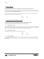
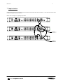
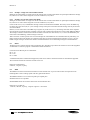
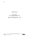
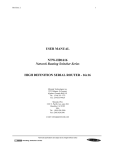
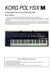
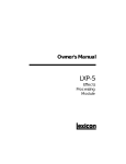
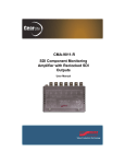
Revision: 0
1
USER MANUAL
NTW-VD1602
Network Routing Switcher Series
DIGITAL VIDEO ROUTER - 16x2
Miranda Technologies inc.
2323 Halpern, St-Laurent
(Quebec) Canada H4S 1S3
Tel.: (514) 333-1772
Fax: (514)333-9828
Miranda USA
1101 N. Pacific Ave, suite 204
Glendale, CA 91202
USA
Tel.: (305) 820-2990
Fax: (305) 820-2991
e-mail: [email protected]
Technical specifications are subject to be changed without notice
Revision: 0
2
Index
0.
Revision history
3
1.
General
4
1.1.
1.2.
Specifications
Connection drawing
2.
Power connection
5
3.
Connecting the NTW-VD1602 to your PC
5
3.1.
3.2.
3.3.
Selection of router address
Pin-out of RS-232 connector
Maximum cable length
4.
MIDI connection
4.1.
4.2.
4.3.
4.4.
4.5.
Several routers in one system
Connecting control panels
Pin-out and cable type
MIDI bus structure
Maximum distance between MIDI devices
5.
Router configuration
5.1.
5.2.
5.3.
Router address
Router extension mode
Vertical interval trigger
6.
Connecting video signals to the NTW-VD1602
8
7.
Input extension
9
8.
Control and connection of Network systems, interface protocol
8.1.
8.1.1.
8.1.2.
8.1.3.
8.1.4.
8.2.
8.2.1.
8.2.2.
8.3.
8.4.
8.5.
8.5.1.
8.5.2.
8.5.3.
Important notes regarding the Network Control Protocol
Binary Code
Acknowledge / Echo
RS-422 Matrixes
Timeout
Basic principles
Example: A single unit with no MIDI connected
Example: Several units connected by MIDI
RS232
MIDI
Commands
Audio crosspoint set
Video crosspoint set
Crosspoint status request
4
4
5
5
5
6
6
6
6
6
7
7
7
8
8
General Environmental Requirements for Network Electronics Equipment
Technical specifications are subject to be changed without notice
10
10
10
10
10
10
10
11
11
11
11
12
12
12
12
13
Revision: 0
3
0. Revision history
Current revision of this document is the uppermost in the table below.
Revision
Replaces
Date
0
-
10/10/00
Change Description
Initial Revision
Technical specifications are subject to be changed without notice
Revision: 0
4
1. General
The NTW-VD1602 is a 16x2 serial digital video router with vertical interval switching and integrated control panel. This
state of the art router provides maximum quality with a data rate of up to 360Mbit/s and automatic cable equalizing. The
NTW-VD1602 offers the possibility to expand the router in the input direction up to 64x2. The NTW-VD1602 is well suited
for all demanding routing tasks in digital studio and broadcast environments. The built-in RS-232 interface allows the user to
control the router via the i-Control PC software with many operational features. The control bus allows linking the unit to the
NTW-AD1602 or NTW-A1602 audio router thus creating a 16x2 AFV router. One or several remote control panels (NTW16-ProX-Y, NTW-16-ProS) can control the NTW-VD1602 as well. The control panel provides buttons for selection of inputs
and 4 function keys with following functions:
•
•
•
•
1.1.
1.2.
OUTPUT 1
OUTPUT 2
AUDIO / VIDEO
ENABLE
Assigns input buttons to output 1
Assigns input buttons to output 2
Enables Audio, Video or AFV
Enables panel
Specifications
Data rate NRZ:
VIT input:
Number of inputs:
Equalization:
Number of outputs:
Auxiliary inputs:
Auxiliary output:
Impedance:
Return-loss in/out:
Signal level:
Rise/fall time:
Connector:
AC power:
DC power:
Dimensions:
143Mbit/s - 360Mbit/s
Comp. Video 1Vpp, 300mV sync, 75 ohms
16 terminated
Automatic up to 300m ( Belden 8281 )
2
4 for router extension
1 for router extension
> 75 ohms
> 18dB (10MHz – 270MHz)
800mV fixed on 75Ohm load
typ. 750ps
BNC
External power supply 100 - 260 VAC
±5V, connector DB9 male
483 x 44 x 45 mm (19”, 1RU)
Connection drawing
Configuration switch
Video input section
MIDI bus
Power connector
Video outputs
Vertical Interval Trigger
RS-232 port
Technical specifications are subject to be changed without notice
Extension Extension
Router
Output
Revision: 0
5
2. Power connection
Do not connect mains to the desk top power supply before connecting the power supply to the router.
Connect the DB9 female connector from the desk top power supply to the main unit. Tighten the screws to assure a proper
contact. To connect mains to the desk top power supply you need a mains cord with IEC 320 connector. NTW-VD1602 uses
the desk top power model AC-10-84-10-005 (±5V / 10W).
If an external power supply is used the NTW-VD1602 router requires ±5V DC with a minimum current of 600mA. The
following pin-out is used on the DB9 male power connector:
Pin 1
Pin 2
Pin 6
0V
+5V
-5V
3. Connecting the NTW-VD1602 to your PC
For connection to a PC with Miranda’s i-Control control software the RS-232 interface is used. The
RS-232 port on all Network devices uses the standard DCE pin-out, see pin-out table under 4.3.
A standard modem cable can be used for connecting the router to the PCs serial port.
3.1.
Selection of router address
The router address depends on the system configuration the router is going to work with. See chapter 5 for more information.
All routers are delivered with default address 0. A router addressed to 0 can be controlled from the i-Control software with
address 0. i-Control offers the control of up to 16 different routers or combinations of routers.
3.2.
Pin-out of RS-232 connector
The DB9 female connector for the RS-232 port has the following pin-out:
Pin 2
Pin 3
Pin 5
Tx
Rx
GND
3.3.
Maximum cable length
The maximum cable length for a RS-232 connection is per definition 15m. Longer distances can be installed depending on
the environmental conditions of the installation site. It is up to the installer / user to secure a proper installation of the RS232 connection.
Technical specifications are subject to be changed without notice
Revision: 0
6
4. MIDI connection
Via the MIDI bus system several routers and control panels can be interconnected. The standard MIDI interface is used on all
Network MIDI control ports. For interconnection between the devices a standard MIDI cable with 5pin DIN connector on
both ends is used. The Network MIDI bus system allows connection of up to 16 routers with different addresses on the same
bus. Routers which are defined to work married e. g. 2 routers as Audio follow Video or 3 routers as RGB (YUV) must be set
on the same address. Control panels dedicated to work with a specific router must have the same address as the router.
Several panels can work together with one specific router. Up to 16 single routers or combinations of routers can be
controlled from one I-Control control screen. The MIDI bus system and all RS-232 ports interchange the system status.
4.1.
Several routers in one system
The Network MIDI bus system allows the interconnection of up to 16 routers with different addresses in one system. A
combination of routers working married counts as one address. This might for example be 1 audio router + 1 video router
working as an audio follow video system or 3 video routers working as a RGB (YUV) system. The routers in such a
constellation have to have the same address.
4.2.
Connecting control panels
To get a control panel working with a specific router, give the control panel the same address as the router. Several panels
can be addressed to the same router. The X-Y panels can control 2 layers with breakaway function. If it is necessary to
control more layers with breakaway an additional panel must be used. Panels can also be connected to a router via the RS232 interface. Please refer to your control panel manual for installation.
4.3.
Pin-out and cable type
The pin-out of all Network MIDI ports follows the standard MIDI specification.
A 1 to 1 cable with 5pin DIN connector is used. The following pin-out is used:
1 - n.c.
1 - n.c.
2 - shield # # # # # # # # # # # # # # # # # # # # # # 2 - shield
3 - n.c.
3 - n.c.
4 - data - - - - - - - - - - - - - - - - - - - - - - - - - - - - - 4 - data data lines must
5 - data - - - - - - - - - - - - - - - - - - - - - - - - - - - - - 5 - data be twisted pair
The standard MIDI specification recommends the use of shielded twisted pair cable types for interconnection between the
units.
4.4.
MIDI bus structure
The Network MIDI bus structure follows the standard MIDI bus definition. The Network MIDI bus is defined as a closed
chain of units. This means that the MIDI OUT of the last unit must be connected to the MIDI IN of the first unit in the
MIDI chain. To avoid problems with the control of Network units the installer/user has to assure that the bus structure is
installed according to this definition. The total number of MIDI devices in a MIDI chain is limited to 50.
Technical specifications are subject to be changed without notice
Revision: 0
7
4.5.
Maximum distance between MIDI devices
The standard MIDI definition allows a maximum cable length of 250 meters between two devices. Longer distances can be
made with MIDI repeater units. To avoid grounding problems all Network MIDI ports have opto-coupled inputs.
5. Router configuration
5.1.
Router address
Switch 1 - 4 on the configuration switch set the router’s address for communication with the i-Control software and other
units in the MIDI bus system. The i-Control control screen and the panels on the MIDI bus dedicated to operate with the
router have to have the same address. If several routers are combined to form an Audio Follow Video, RGB or similar system,
these routers have to have the same address.
The addresses can be switched according to the following pattern:
*
means switch down
means switch up
Default address is 0.
Switch
1
2
3
4
*
*
*
*
*
*
*
*
*
*
*
*
*
*
*
*
*
*
*
*
*
*
*
*
*
*
*
*
*
*
*
*
Address
0
1
2
3
4
5
6
7
8
9
10
11
12
13
14
15
Technical specifications are subject to be changed without notice
Revision: 0
8
5.2.
Router extension mode
Switch 5, 6 and 7 on the configuration switch set the router’s input offset in systems with 2 or more NTW-VD1602. You can
build systems up to 64x2. The chosen input offset defines on which input range each
NTW-VD1602 works on.
The offset can be switched according to the following pattern:
*
means switch down
means switch up
Switch
5
6
7
Offset
-
*
*
*
*
0
16
32
48
Switch 5 is always in position down.
Default is offset 0.
5.3.
Vertical interval trigger
Switch 8 on the configuration switch enables or disables the VIT sensing on VIT input. If VIT switching is enabled but a
proper signal is missing, the router will automatically switch without VIT.
The VIT can be switched according to the following pattern:
*
means switch down
means switch up
Switch
8
VIT
*
disabled
enabled
Default is VIT enabled.
6. Connecting video signals to the NTW-VD1602
The NTW-VD1602 router offers standard 75 ohms BNC connectors for digital video in- and outputs. All digital video inputs
are terminated with 75 ohms.
Technical specifications are subject to be changed without notice
Revision: 0
9
7. Input extension
NTW-VD1602 allows input extension up to 64x2. Please connect the routers as shown below. A 4x1 extension router is used
to collect the signal from several units.
Please refer to chapter 5.2 regarding input offset.
Technical specifications are subject to be changed without notice
Revision: 0
10
8. Control and connection of Network systems, interface protocol
8.1.
Important notes regarding the Network Control Protocol
8.1.1. Binary Code
The strings shown on the next pages are in binary coded format. Please be aware of the fact that any terminal program you
may use to control a Network unit from a PC must be able to generate hexadecimal characters. ASCII characters will not be
accepted.
8.1.2. Acknowledge / Echo
A matrix will reply on a crosspoint set command with an ECHO. In the case where a crosspoint is already set no ECHO will
be sent. If the matrix is part of a MIDI system two types of reply will be sent. Immediately after receiving the crosspoint set
command the ECHO will be sent. The matrix will then wait for the command to pass the MIDI bus system. After receiving
the command from the MIDI bus system the matrix will send the command as an ACKNOWLEDGE.
8.1.3. RS-422 Matrixes
RS-422 Data Routers do not accept distribution of an input signal to several outputs. An input signal can only be routed to
one single output. The Firmware of our RS-422 routers takes care of these limitations. If an input (Source) is already
connected to a particular output (Destination) any connection of this input to another output will disconnect the previous
connection. The router will in this case send the following message for the disconnected output: Output connected to input
128. Input 128 is an internal default for the disconnect status. Please see Network recommendations for use of RS-422 data
routers for further information.
8.1.4. Timeout
The Crosspoint Status Request message has a timeout, which means that you need to wait 1 second in between request
messages.
8.2.
Basic principles
Any message on any level (address) which conforms to the standard arriving at either the MIDI or the RS232 port, will be resent on both MIDI and RS232. The only exceptions are:
a) A matrix which recognizes its address will not re-transmit the message if the crosspoint is already set.
b) A matrix which recognizes its address will not re-transmit the message if the output number or input number
exceeds its size.
c) A unit (matrix or panel) will not re-transmit a message arriving at the MIDI if it was re-transmitted a short while
ago (typically 0.5 sec). This is done by grabbing a message storing it for the timeout period, and comparing it with
new messages. After the timeout period the unit will grab a new message for compare. This is done to remove
unwanted (read: unknown) messages from the MIDI ring.
d) A message arriving at the RS232 will always be re-transmitted unless it is a matrix, and one of the cases a) or b) is
fulfilled.
Technical specifications are subject to be changed without notice
Revision: 0
11
8.2.1. Example: A single unit with no MIDI connected
Messages sent to the RS232 of a single unit will be returned once no matter what address or input/output number the message
has, unless it is a matrix which recognizes one of the conditions a) or b) above.
8.2.2. Example: Several units connected by MIDI
Messages sent to the RS232 of a single unit will be returned once no matter what address or input/output number the message
has, unless it is a matrix which recognizes one of the conditions a) or b) above.
If none of the cases a) or b) is fulfilled the message will also be transmitted on the MIDI. Then if any unit on the MIDI ring
recognizes any of the cases a)/b) or c), the message will stop at that point. This means that the message will only be returned
once on the RS232.
However, if none of the units on the MIDI ring recognizes any of the cases a) to c), the message will return to the originator
(the unit which received the message on RS232). This unit will re-transmit the message once more on both MIDI and RS232.
The message is therefore returned a second time on RS232. This time one of the cases a) or c) is sure to be identified by one
of the units on the MIDI ring, and the message is removed.
There is however one more special case: If several messages for unused addresses are transmitted with only little delay, one
might experience that some messages are returned several times, as the store/compare/remove function in case c) can only
handle a single message at the time. We therefore recommend that the user avoid sending messages to unused addresses.
8.3.
RS232
The RS-232 port is used for external control of Network units. The RS-232 port allows the customer to control the equipment
via Miranda's i-Control PC program or self-defined customized solutions.
Connector for the RS-232 port is a DS9 female.
Pin 2 - Tx.
Pin 3 - Rx
Pin 5 - GND
A standard DCE (Data Communication Equipment) cable can be used for connection between PC and Network equipment.
The connection between the connectors is made one-to-one.
Data-rate is 9600 baud/sec.
8 data-bit, 1 stop-bit, no parity.
8.4.
MIDI
The MIDI bus is used for interconnection between several Network units. Up to 50 routers and/or control panels can be
linked together to form a routing system with many operational features.
The MIDI bus utilises a 5 mA current loop with opto coupled ports.
Standard connector is a 5pin DIN.
Standard MIDI cables can be used to interconnect several Network units.
Data-rate is 31.25 kbit/sec.
1 start-bit, 8 data-bit, no parity, 1 stop-bit. Logical 0 = current ON.
Technical specifications are subject to be changed without notice
Revision: 0
8.5.
12
Commands
8.5.1. Audio crosspoint set
Only for use with Audio routers.
Command for setting of crosspoints:
1001nnnn
0kkk kkkk
0vvv vvvv
- nnnn is the matrix address from 0 up to 15.
- kkk kkkk is the output which shall be controlled.
kkk kkkk = output number
0 = output 1
127 = output 128
- vvv vvvv is the input which shall be connected to the chosen output.
vvv vvvv = input number
8.5.2. Video crosspoint set
Only for use with Video routers.
Command for setting of crosspoints:
1010nnnn
0kkkkkkk
0vvvvvvv
- nnnn is the matrix address from 0 up to 15.
- kkk kkkk is the output which shall be controlled.
kkk kkkk = output number
0 = output 1
127 = output 128
- vvv vvvv is the input which shall be connected to the chosen output.
vvv vvvv = input number
8.5.3. Crosspoint status request
This command is used for status request on Audio and Video routers.
1100nnnn
0xxxxxxx
- nnnn is the matrix address from 0 up to 15.
- xxxxxxx - do not carry any information
The requested router (Audio or Video) will send its crosspoint status on MIDI OUT and RS232. The same command format
as for crosspoint set is used.
Technical specifications are subject to be changed without notice
Revision: 0
13
General Environmental Requirements for
Network Electronics Equipment
1. The equipment will meet the guaranteed performance specification under the following
environmental conditions:
• Operating room temperature range 0°C to 45°C
Except of digital video routers
0°C to 40°C
• Operating relative humidity range up to 90% (non-condensing)
2. The equipment will operate without damage under the following environmental
conditions:
• Temperature range
• Relative humidity range
-10°C to 55°C
up to 95% (non-condensing)
3. Electromagnetic compatibility conditions:
EN 55103-1 (Directive 89/336/EEC)
• Emissions
EN 55103-2 (Directive 89/336/EEC)
• Immunity
EN 60 950
• Electrical safety
With reference to the declaration of conformity provided with the external power supply.
Technical specifications are subject to be changed without notice
Revision: 0
14
Network Electronics AS
Hinderveien 4, 3204 Sandefjord, Norway
Tel.: +47 33 48 99 99 Fax: +47 33 48 99 98 e-mail: [email protected]
Declaration of Conformity with CE
This apparatus meets the requirements of EN 55103-1 (November 1996) with regard to
emissions, and EN 55103-2 (November 1996) with regard to immunity; it thereby complies
with the Electromagnetic Compatibility Directive 89/336/EEC.
Regarding electrical safety we refer to the declaration of conformity provided with the
external power supply.
Technical specifications are subject to be changed without notice