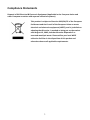
1
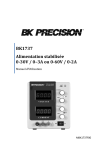
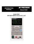
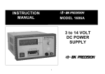
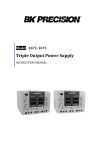
Model 1737
Dual Range DC Power Supply
INSTRUCTION MANUAL
1
Safety Summary
The following safety precautions apply to both operating and maintenance personnel and
must be observed during all phases of operation, service, and repair of this instrument.
Before applying power, follow the installation instructions and become familiar with the
operating instructions for this instrument.
GROUND THE INSTRUMENT
To minimize shock hazard, the instrument chassis and cabinet must be
connected to an electrical ground. This instrument is grounded through the
ground conductor of the supplied, three-conductor ac power cable. The power
cable must be plugged into an approved three-conductor electrical outlet. Do not
alter the ground connection. Without the protective ground connection, all
accessible conductive parts (including control knobs) can render an electric
shock. The power jack and mating plug of the power cable meet IEC safety
standards.
DO NOT OPERATE IN AN EXPLOSIVE ATMOSPHERE
Do not operate the instrument in the presence of flammable gases or fumes.
Operation of any electrical instrument in such an environment constitutes a
definite safety hazard.
KEEP AWAY FROM LIVE CIRCUITS
Instrument covers must not be removed by operating personnel. Component
replacement and internal adjustments must be made by qualified maintenance
personnel. Disconnect the power cord before removing the instrument covers
and replacing components. Under certain conditions, even with the power cable
removed, dangerous voltages may exist. To avoid injuries, always disconnect
power and discharge circuits before touching them.
DO NOT SERVICE OR ADJUST ALONE
Do not attempt any internal service or adjustment unless another person,
capable of rendering first aid and resuscitation, is present.
DO NOT SUBSTITUTE PARTS OR MODIFY THE INSTRUMENT
Do not install substitute parts or perform any unauthorized modifications to this
instrument. Return the instrument to B&K Precision for service and repair to
ensure that safety features are maintained.
1
WARNINGS AND CAUTIONS
WARNING and CAUTION statements, such as the following examples, denote a
hazard and appear throughout this manual. Follow all instructions contained in
these statements.
A WARNING statement calls attention to an operating procedure, practice, or
condition, which, if not followed correctly, could result in injury or death to
personnel.
A CAUTION statement calls attention to an operating procedure, practice, or
condition, which, if not followed correctly, could result in damage to or
destruction of parts or the entire product.
WARNING:
Do not alter the ground connection. Without the protective
ground connection, all accessible conductive parts (including
control knobs) can render an electric shock. The power jack and
mating plug of the power cable meet IEC safety standards.
WARNING:
To avoid electrical shock hazard, disconnect power cord before
removing covers. Refer servicing to qualified personnel.
CAUTION:
Before connecting the line cord to the AC mains, check the rear
panel AC line voltage indicator. Applying a line voltage other
than the indicated voltage can destroy the AC line fuses. For
continued fire protection, replace fuses only with those of the
specified voltage and current ratings.
CAUTION:
This product uses components which can be damaged by electrostatic discharge (ESD). To avoid damage, be sure to follow
proper procedures for handling, storing and transporting parts
and subassemblies which contain ESD-sensitive components.
SAFETY SYMBOLS
Connect to safety earth ground using the wire recommended in the user
manual.
This symbol on an instrument indicates that the user should refer to the
operating instructions located in the manual.
Certification
We certify that this product met its published specifications at time of shipment from the
factory.
2
Compliance Statements
Disposal of Old Electrical & Electronic Equipment (Applicable in the European Union and
other European countries with separate collection systems)
This product is subject to Directive 2002/96/EC of the European
Parliament and the Council of the European Union on waste
electrical and electronic equipment (WEEE), and in jurisdictions
adopting that Directive, is marked as being put on the market
after August 13, 2005, and should not be disposed of as
unsorted municipal waste. Please utilize your local WEEE
collection facilities in the disposition of this product and
otherwise observe all applicable requirements.
3
Contents
1 Safety Summary .......................................................... 1
2 Introduction ................................................................ 5
3 Quick Reference .......................................................... 6
4
5
6
7
3.1
3.2
Front Panel ......................................................................................... 6
Rear Panel .......................................................................................... 7
4.1
4.2
4.3
4.4
4.5
4.6
4.7
4.8
Instrument Hook-Up .......................................................................... 9
Typical Constant Voltage Operation................................................. 11
Setting Current Limit ........................................................................ 12
Typical Constant Current Operation ................................................ 13
Constant Voltage/Constant Current Characteristic.......................... 14
Saving the Power Supply’s Current State ......................................... 15
Connecting Two Power Supplies in Series ....................................... 15
Connecting Two Power Supplies in Parallel ..................................... 16
5.1
5.2
5.3
RS232 Configuration Overview ........................................................ 18
RS232 Commands ............................................................................ 18
Application Software ....................................................................... 19
6.1
6.2
6.3
6.4
Fuse Replacement............................................................................ 20
Adjustments ..................................................................................... 20
Calibration ....................................................................................... 21
Instrument Repair Service ............................................................... 26
7.1
7.2
7.3
Self-Test Errors ................................................................................. 27
Calibration Errors ............................................................................. 27
Command Errors .............................................................................. 28
Operating Instructions ................................................. 8
Remote Operation ......................................................17
Maintenance ..............................................................20
Error Messages ...........................................................27
8 Specifications .............................................................29
9 Service Information ....................................................31
10 Limited Two-Year Warranty........................................32
4
2
Introduction
Description
The B&K Precision model 1737 is a general purpose dual range DC power source.
This power supply can output more voltage at a lower current or more current at
a lower voltage. The 1737 provides 0-60 V DC output, adjustable with both
coarse and fine voltage controls for precise setting. The current output for the
1737 is 0-3 A for the 0-30 V range, and 0-2 A for the 30-60 V range, adjustable
with both coarse and fine current controls.
The 1737 exhibits excellent regulation and low ripple characteristics. Its
mechanical configuration conserves bench space and allows for easy portability.
Additionally, the power supply can be operated locally from the front panel or
remotely through the RS-232 interface.
This power supply is well suited for a wide variety of electrical and electronics
applications in service shops, engineering labs, production facilities, school
laboratories, and home use.
Features
•
•
•
•
•
•
•
•
•
•
Low ripple and noise
Excellent regulation
Constant voltage (CV) and constant current (CC) operation
Two 4-digit LED displays provide good visibility in bright or low light
LED indication for CV and CC modes
Automatic recall of last settings on power up
RS-232 interface
Isolated output
Overload protection
Reverse polarity protection
5
3
Quick Reference
3.1 Front Panel
5
3
1
6
7
4
8
2
9
10
11
12
Figure 1 - Front Panel
INDICATORS
Either the CV or CC LED indicators will be lit whenever the unit is operating. The unit
automatically changes from CV to CC operation when the preset current limit is
reached.
1) CV (Constant Voltage) Indicator. The green LED is lit in constant voltage mode.
Unit regulates output voltage at the value set by voltage controls.
2) CC (Constant Current) Indicator. The red LED is lit in constant current mode. Unit
regulates output current at the value set by current controls.
3) Green LED Display. 4-digit display continuously monitors voltage.
4) Red LED Display. 4-digit display continuously monitors current.
VOLTAGE CONTROLS
5) Voltage Coarse Control. Coarse adjustment of output voltage. Read value on the
green LED display.
6) Voltage Fine Control. Fine adjustment of output voltage. Read value on the
green LED display.
6
CURRENT CONTROL
7) Current Coarse Control. Coarse adjustment of current limit. Read value on the
red LED display.
8) Current Fine Control. Fine adjustment of current limit. Read value on the red LED
display.
POWER CONTROLS
9) Power ON-OFF Switch.
OUTPUT TERMINALS
10) “-” Terminal (Black). Negative polarity output terminal.
11) GND Terminal. Earth and chassis ground.
12) “+” Terminal (Red). Positive polarity output terminal.
3.2 Rear Panel
13
15
14
Figure 2 - Rear Panel
13) Power Cord
14) Fuse
15) RS-232 Interface Connector
7
4
Operating Instructions
Safety Precautions
Use only a polarized 3-wire AC outlet. This assures that the power supply chassis,
case, and ground terminal are connected to a good earth ground and reduces
danger from electrical shock.
There is little danger of electrical shock from the power supply output, which
produces a maximum of 60 volts dc. However, there may be great danger of
electrical shock if the power supply output is connected to an external high
voltage. Some equipment being powered may contain high voltage and present a
shock hazard. Observe caution. If the power supply output is floated (referenced
to a voltage rather than earth ground) turn off the power supply and the
equipment under test when making connections. Never float the power supply to
a potential greater than 100 volts peak with respect to earth ground.
Equipment Precautions
Avoid using the power supply in ambient temperatures above +40° C. Always
allow sufficient air space around the heat sink at the rear of the power supply for
effective radiation to prevent internal heat build-up.
Although the power supply is protected against reverse polarity damage, the
circuit being powered may not include such protection. Always carefully observe
polarity; incorrect polarity may damage the equipment under test.
Do not exceed the voltage rating of the circuit being powered. Many transistors
and integrated circuits will not withstand voltage of 60 volts.
There is no need to worry about voltage spikes or overshoot damaging the
equipment under test. The voltage between the output terminals of the power
supply never exceeds the preset value as the POWER switch is turned on or off.
8
4.1 Instrument Hook-Up
1.
2.
3.
4.
Turn off the power supply and the equipment to be powered during hookup.
Connect the positive polarity of the device being powered to the red (+)
terminal of the power supply.
Connect the negative polarity of the device being powered to the black (-)
terminal of the power supply.
Figure 3 illustrates the grounding possibilities.
a. If the negative polarity of the equipment or circuit being powered is also
the chassis or common, it may be grounded to earth by strapping the black
(-) terminal to the green ( ) terminal as shown in Figure 3A.
b. Similarly, the positive polarity can be grounded by strapping the red (+)
terminal to the green ( ) terminal as shown in Figure 3B.
c. If an earth ground reference is not required, the configuration of Figure 3C
may be used. The scheme in Figure 3C should also be used where it is not
known whether the chassis is common with either the positive or negative
polarity.
d. If the chassis or common of the equipment being powered is separate
from both the positive and negative polarity power inputs, use the
connection shown in Figure 3D.
6. Observe proper polarity. If the circuit being powered is not equipped with
reverse polarity protection, damage to the circuit can result from reverse
polarity. Use color coded hook-up leads, for convenience in identifying
polarity, red for (+) and black for (-).
7. Make sure that the hook-up leads offer sufficient current capability and low
resistance between the power supply and the circuits being powered.
9
Figure 3 (A and B) - Grounding Possibilities
Figure 3 (C and D) - Grounding Possibilities
10
4.2 Typical Constant Voltage Operation
1.
2.
3.
4.
5.
6.
7.
Before connecting the device to be powered to the power supply, determine
the maximum safe load current for the device to be powered and set the
current limit value (see Setting Current Limit procedure in this section).
The output voltage can be set using the voltage coarse knob (with a 1 V
resolution) and voltage fine knob (with a 10 mV resolution). After the last
adjustment you must wait 3 seconds until the state is saved.
Turn off power supply and connect it to the device to be powered (see
Instrument Hook-Up procedure in this section).
Turn on the power switch. The CV indicator should light.
Increase the voltage setting until the voltage LED display reads the desired
value. The fine control permits easier setting to a specific value.
Note the load current on the current LED display.
If the load current exceeds the preset current limit, the CV indicator will go
off and the CC indicator will light. In this case, the power supply
automatically switches to the constant current mode, and further rotation of
the voltage control will not increase the output voltage.
Figure 4 - Typical Constant Voltage Operation
11
4.3 Setting Current Limit
1.
2.
3.
4.
5.
Determine the maximum safe current for the device to be powered.
Temporarily short the (+) and (-) terminals of the power supply together
with a test lead.
Adjust the coarse and fine current control for the desired current limit. Read
the current value on the current LED display.
The current limit (overload protection) has now been preset. Do not change
the current controls settings after this step.
Remove the short between the (+) and (-) terminals and hook up for constant
voltage operation.
Figure 5 - Setting Current Limit
12
4.4 Typical Constant Current Operation
1.
2.
3.
4.
5.
6.
7.
Before connecting the device to be powered to the power supply, determine the
maximum safe voltage to be applied, and set the voltage controls to obtain that
voltage reading on the voltage LED display.
Determine the desired constant current value.
Set the coarse and fine current control to minimum (1 mA). Wait 3 seconds.
Turn off the power supply and connect it to the device to be powered.
Turn on the power supply. The CC indicator should light.
Increase the coarse and fine current control setting until the desired constant
current value is read on the display, or set the current limit in advance (before
connecting the load) as described earlier in the Setting Current Limit procedure.
If the load current drops below the constant current value, the CC indicator will go
off and the CV indicator will light. In this case, the power supply automatically
switches to the constant voltage mode, and further rotation of the current
controls will not increase the output current.
Figure 6 - Typical Constant Current Operation
13
4.5 Constant Voltage/Constant Current Characteristic
The working characteristic of this power supply is called a constant voltage/constant
current automatic crossover type. This permits continuous transition from constant
current to constant voltage modes in response to the load change. The intersection
of constant voltage and constant current modes is called the crossover point. Figure
7 shows the relationship between this crossover point and the load.
For example, if the load is such that the power supply is operating in the constant
voltage mode, a regulated output voltage is provided. The output voltage remains
constant as the load decreases, up until the point where the preset current limit is
reached. At that point, the output current becomes constant and the output voltage
drops in proportion to further decreases in load. The crossover point is indicated by
the front panel LED indicators. The crossover point is reached when the CV indicator
goes off and the CC indicator comes on.
Similarly, crossover from the constant current to the constant voltage mode
automatically occurs from an increase in load. A good example of this would be seen
when charging a 12-volt battery. Initially, the open circuit voltage of the power
supply may be preset for 13.8 volts. A low battery will have a low load on the supply
and it will operate in the constant current mode, which may be adjusted for a 1 amp
charging rate. As the battery becomes charged, and its voltage approaches 13.8 volts,
its load increases to the point where it no longer demands the full 1 amp charging
rate. This is the crossover point where the power supply goes into the constant
voltage mode.
Figure 7 - Constant Voltage/Constant Current Characteristic
14
4.6 Saving the Power Supply’s Current State
The current state of the power supply is saved after 2 seconds from the last
adjustment or after the “SAVE” command is received through the RS232 interface.
4.7 Connecting Two Power Supplies in Series
Two power supplies may be connected in series to provide a variable 0-120 V output.
In this configuration, the two power supplies can supply up to 60 V-3 A or 120 V-2 A.
See Figure 8 for the connection scheme.
When connected in series, the voltage controls of each power supply exercise control
over a 0-60 V range. Add the LED display readings together or connect an external
voltmeter across the load to determine the total output voltage.
Load current may be monitored from either supply; the readings will be identical
since they are connected in series. Also, since the supplies are connected in series, it
is only necessary to set the current limit on one of the supplies; the other may be set
for maximum.
Figure 8 - Connecting Two Power Supplies in Series
15
4.8 Connecting Two Power Supplies in Parallel
Two power supplies may be connected in parallel to double the maximum load
current. In this configuration, the two power supplies will provide 0-60 V output
at up to 4 A or 0-30 V at 6 A (heavier gauge hook-up leads are advisable). Current
equalizing resistors must be used as shown in Figure 9. However, the protective
current limiting feature will prevent damage if current is temporarily unbalanced
during set-up.
When connected in parallel and operating in the constant voltage mode,
determine the total load current limit and preset the current limiting for each
power supply to half the total load current value. Then when the load is
connected, set the voltage controls on the two power supplies for equal voltage
readings. This should also provide approximately equal current from each supply.
Add the two current meter readings together for total load current, or connect
an external ammeter in series with the load.
Figure 9 - Connecting Two Power Supplies in Parallel
16
If the current equalizing resistors are not well matched, it is preferable that the
voltages be slightly unbalanced to achieve current balance. Be sure that the
supplies are adequately balanced so that both remain in the CV mode.
When connected in parallel and operating in the constant current mode, the
voltage controls of both supplies should be preset to the same value. Then when
the load is connected, the current controls of the two supplies should be
adjusted for approximately equal current from each unit. Be sure that both
supplies remain in the CC mode.
5
Remote Operation
The power supply can be connected to the RS232 interface using the 9-pin (DB-9)
serial connector on the rear panel. The 1737 uses a null modem RS232 cable. The
cable pin diagram for the DB-9 connector is shown in the picture below:
Instrument
RX
PC
2
3
RX
TX
2
3
GND
5
5
GND
DB-9
connector
TX
DB-9
connector
Figure 10 - RS232 Cable Pin Diagram
For all communications over the RS232 interface, the power supply uses Xon/Xoff
protocol.
NOTE: If using HyperTerminal, make sure you properly configure the “ASCII Setup”. In
“ASCII Setup”, do not append line feeds to “ASCII Sending”. “Echo typed characters
locally” can be checked, but “Send line ends with line feeds” should be left
unchecked. In “ASCII Receiving”, “Append line feeds to incoming line ends” can also
be checked.
17
5.1 RS232 Configuration Overview
Baud Rate
9600 bps
Parity Bits
none
Data Bits
8
Start Bits
1
Stop Bits
1
Flow Control
Xon / Xoff
Termination Character
\r
Table 1 - RS232 Configuration
5.2 RS232 Commands
1.VOLT xx.xx<CR>
This command sets the output voltage value. The output voltage takes the
programmed value only if the power supply is in Constant Voltage mode.
Example: The output voltage is set at 5 V.
VOLT 05.00<CR>
2. CURR x.xxx<CR>
This command sets the output current value. The output current takes the
programmed value only if the power supply is in Constant Current mode.
Example: The output current is set at 300 mA.
CURR 0.300<CR>
18
3. SAVE<CR>
The programmed values of the output current and voltage are saved. If the
power supply is restarted, the values of the output current and voltage will
be those previously saved.
4. VOLT?<CR>
This command returns the voltage measured to the output terminals of the
power supply: xx.xxV<CR>
The voltage value returned is the same as the one displayed on the voltage
display.
5. CURR?<CR>
This command returns the current measured to the output terminals of the
power supply: x.xxxA<CR>
The current value returned is the same as the one displayed on the current
display.
6. STAT?<CR>
The power supply responds to this command with one of the following
messages:
CV<CR> if the power supply is in Constant Voltage mode
CC<CR> if the power supply is in Constant Current mode
5.3
Application Software
Remotely control your 1737 using B&K Precision’s application software, available for
download at www.bkprecision.com. This software provides a virtual front panel and
a simple data logging function to store and log data to a text or CSV file. RS232
commands can also be sent through the software.
19
6
Maintenance
WARNING
The following instructions are for use by qualified personnel only. To avoid electrical
shock, do not perform any servicing other than contained in the operating
instructions unless you are qualified to do so.
6.1 Fuse Replacement
If the fuse blows, the CV or CC indicators will not light and the power supply will not
operate. The fuse should not normally open unless a problem has developed in the
unit. Try to determine and correct the cause of the blown fuse, then replace only
with a fuse of the correct rating as listed below. The fuse is located on the rear panel
(see Figure 2).
Line Voltage
Fuse
Type
120 Vac ± 10%, 50/60 Hz
2.5A
Slow Blow
220 Vac ± 10%, 50/60 Hz
1.25A
Slow Blow
Table 2 - Fuse Values
Line Voltage Conversion, International Units
The primary winding of the power transformer is tapped to permit operation from
120/220/230 or 240 VAC, 50/60 Hz line voltage. Conversion from one line voltage to
another is done by a simple position change of the fuse receptacle underneath the
line cord.
6.2 Adjustments
This unit was accurately adjusted at the factory before shipment. Readjustment is
recommended only if repairs have been made in a circuit affecting adjustment
accuracy, or if you have a reason to believe the unit is out of adjustment. However,
adjustments should be attempted only if a multimeter with an accuracy of ±0.02%
DCV or better is available (B&K Precision Model 5491B or equivalent).
20
6.3 Calibration
Calibration is a procedure that ensures that the power supply will work properly,
with parameters specified within the Specifications section.
Before initiating the calibration procedure, the following conditions must be assured:
• Disconnect any loads connected to the power supply and turn it on
• Let the power supply be turned on for 1 hour with no loads connected before
you start the calibration procedure
• Calibration ambient temperature must be 25°C
• Ambient relative humidity must be less than 80%
To calibrate the power supply, complete the following steps:
1. Turn on the power supply in calibrating mode
2. Zero voltage calibration
3. Full voltage calibration
4. Zero current calibration
5. Full current calibration
6. Leaving the Calibration menu
Figure 11 - Location of Adjustments
21
1.
Turn on the power supply in calibrating mode
a)
Turn off the power supply. Disconnect the power cord and all loads
connected to the power supply.
b) Remove power supply’s cover.
c)
Set the calibration jumper as shown in Figure 11.
d) Reassemble the power supply.
e)
Connect the power cord to the power supply.
f)
Turn on the power supply in Calibration menu. The power supply will
display:
Voltage display: C A L
Current display: U 0
You can browse the calibration menu by turning the current coarse knob. Using the
voltage coarse knob you can select one of the following calibration procedures:
U
U
I
I
0
F
0
F
Zero voltage calibration
Full voltage calibration
Zero current calibration
Full current calibration
The voltage fine and current fine knobs are not used.
Important note!
In order to perform a correct calibration procedure, you must select the full voltage
calibration option just after the zero voltage calibration option, and the full current
calibration option just after the zero current calibration option.
22
2.
Zero voltage calibration
a)
Turn the current coarse knob to select “U 0” for zero voltage calibration
and turn the voltage coarse knob. The power supply will display:
Voltage display:
U 0
Current display: hex number
On the current display, a hexadecimal number between 0 and FFFFh is
displayed. During the zero voltage calibration, the CV LED is lit.
b) Connect a digital voltmeter to the output terminals of the power supply
(B&K Precision 5491B or similar instrument).
c)
Use the current coarse and fine knobs to adjust the value displayed by the
power supply until the voltmeter indicates the closest value to 0 V.
d) Turn the voltage coarse knob to finish the calibration.
While performing the zero voltage calibration, the current display will show
Adc. After the zero voltage calibration, the message Done is shown on the
current display for 1 sec. Then the power supply returns to the Calibration
menu.
3.
Full voltage calibration
To finish the voltage calibration procedure, the full voltage calibration must be done
after the zero voltage calibration.
a)
Select “U F” for full voltage calibration and turn the voltage coarse knob.
The power supply will display:
Voltage display:
U F
Current display: hex number
23
A hexadecimal number between 0 and FFFFh will be shown on the current
display. During the zero voltage calibration, the CV LED is lit.
b) Connect a digital voltmeter to the output terminals of the power supply
(B&K Precision 5491B or similar instrument).
c)
Use the current coarse and fine knobs to adjust the value displayed by the
power supply until the voltmeter indicates the value to 60.882 V.
d) Turn the voltage coarse knob to finish the calibration.
While performing the full voltage calibration the current display will show
Adc. After the full voltage calibration the message Done is shown on the
current display for 1 sec. Then the power supply returns to the Calibration
menu.
4.
Zero current calibration
a)
Select “I 0” for zero current calibration and turn the voltage coarse knob.
When you initiate the zero current calibration, the CV LED lights up and the
power supply will display:
Voltage display: I 0
Current display: ConA
b) Connect a digital ammeter (B&K Precision 5491B or similar instrument) to
the output terminals of the power supply to initiate the zero current
calibration procedure. If a digital ammeter is not connected within 30
seconds, the power supply will abandon the current calibration procedure
and return to the Calibration menu.
The CV LED indicator will go off and the CC LED indicator will light on. The
power supply will then display:
Voltage display: I 0
Current display: hex number
24
A hexadecimal number between 0 and FFFFh is shown on the current
display.
c)
Use the current coarse and fine knobs to adjust the value displayed by the
power supply until the ammeter indicates the closest value to 0 A.
d) Turn the voltage coarse knob to finish the calibration.
While performing the zero current calibration, the current display will show
Adc. After the zero current calibration, the message Done is shown on the
current display for 1 sec. Then the power supply returns to the Calibration
menu.
5.
Full current calibration
To finish the current calibration procedure, you must select the full current
calibration option after the zero current calibration.
a)
Select “I F” for full current calibration and turn the voltage coarse knob.
When you initiate the full current calibration, the CV LED lights up and the
power supply will display:
Voltage display: I F
Current display: ConA
b) Connect a digital ammeter (BK Precision 5491B or similar instrument) to the
output terminals of the power supply to initiate the full current calibration
procedure. If a digital ammeter is not connected within 30 seconds, the
power supply will abandon the current calibration procedure and will return
to the Calibration menu.
The CV LED indicator will turn off and the CC LED indicator will light on. The
power supply will then display:
Voltage display: I F
Current display: hex number
25
A hexadecimal number between 0 and FFFFh is shown on the current
display.
c)
Use the current coarse and fine knobs to adjust the value displayed by the
power supply until the ammeter indicates the value to 3.0801 A.
d) Turn the voltage coarse knob to finish the calibration.
While performing the full current calibration, the current display will show
Adc. After the full current calibration, the message Done is shown on the
current display for 1 sec. The power supply does not return to the
Calibration menu because the calibration procedure is finished and the
power supply must be turned off.
6.
Leaving the calibration menu
a)
After turning off the power supply, disconnect the power cord.
b) Remove power supply’s cover.
c)
Remove the calibration jumper.
d) Reassemble the power supply.
e)
Connect the power cord.
f)
When turned on, the power supply will have the same parameters
programmed and saved before the calibration procedure.
6.4 Instrument Repair Service
Because of the specialized skills and test equipment required for instrument repair
and calibration, many customers prefer to rely upon B&K Precision for this service.
We maintain a network of B&K Precision authorized service agencies for this
purpose. To use this service, even if the instrument is no longer under warranty,
follow the instructions given in the Warranty Service Instructions section of this
manual. There is a nominal charge for instruments out of warranty.
26
7
Error Messages
The following types of errors may occur:
• Self-test errors
• Calibration errors
• Command errors
The first two types of errors are displayed on the voltage display as: Er xx, where xx is
a number. The command errors are sent through the RS232 interface.
7.1 Self-Test Errors
Er 01: EEPROM does not respond
Er 02: CV not high
Er 03: CV not low
Er 04: CC not high
Er 05: CC not low
Er 06: ADC does not respond
Er 07: ADC not ready
Er 08: No reference voltage
Er 09: ADC conversion error
Er 10: ADC AVdd< 3.0V
Er 11: ADC AVdd> 3.6V
Er 12: Calibration constants checksum failed
7.2 Calibration Errors
Zero voltage calibration errors
Er 20: CC not high
Er 21: CV not low
Er 22: DAC out of range
Er 23: ADC out of range
Er 24: ADC system calibration failed
Er 25: DAC zero voltage constant checksum failed
Er 26: ADC zero voltage constant checksum failed
27
Full voltage calibration errors:
Er 30: CC not high
Er 31: CV not low
Er 32: DAC out of range
Er 33: ADC out of range
Er 34: ADC system calibration failed
Er 35: DAC full voltage constant checksum failed
Er 36: ADC full voltage constant checksum failed
Zero current calibration errors:
Er 40: CC not low
Er 41: CV not high
Er 42: DAC out of range
Er 43: ADC out of range
Er 44: ADC system calibration failed
Er 45: DAC zero current constant checksum failed
Er 46: ADC zero current constant checksum failed
Full current calibration errors:
Er 50: CC not low
Er 51: CV not high
Er 52: DAC out of range
Er 53: ADC out of range
Er 54: ADC system calibration failed
Er 55: DAC full current constant checksum failed
Er 56: ADC full current constant checksum failed
7.3 Command Errors
”Communication Error<CR>”
“Syntax Error<CR>”
“Out of range<CR>”
: RS232 framing, parity, or overrun error
: invalid syntax was found in the command string
: a numeric parameter value is outside the valid range
for the command
28
8
Specifications
1737
Output Ratings ( 0 °C~40 °C)
0-60 V
0-3 A (0-30 V),
0-2 A (30-60 V)
Voltage
Current
Load Regulation ±(% of output+offset)
Voltage
Current
Line Regulation ±(% of output+offset)
0.01% + 3 mV
0.2% + 3 mA
Voltage
Current
Ripple & Noise (20 Hz ~ 20 MHz)
0.01% + 3 mV
0.2% + 3 mA
Voltage
Current
Recovery Time
Meter Resolution
1 mVrms
≤ 3 mArms
≤ 100 μs
Voltage
Current
Metering Accuracy
10 mV
1 mA
0.5% + 9 digits
0.5% + 9 digits
Voltage
Current
General
Power Requirements
Power Consumption
Protection
Operating Environment
Temperature
Humidity
Temperature coefficient (0 °C~35 °C)
±(%of output+offset)
120/220 VAC ±10%, 50/60 Hz
≤ 180 W
Reverse polarity, current limiting
32 °F to 104 °F (0 °C to 40 °C)
75% R.H.
300 ppm/°C
Storage Temperature
5 °F to 158 °F (-15° to +70° C)
29
Storage Humidity
Mechanical Specifications
85% R.H.
10.5 lbs (4.8 kg)
5.5” x 6.2” x 12.5"
(140 x 158 x 318 mm)
Power cord, instruction manual,
RS-232 cable, shorting bar
Weight
Dimensions (W x H x D)
Supplied Accessories
NOTE: All specifications apply to the unit after a temperature stabilization time of 30
minutes. Specifications and information are subject to change without notice.
To ensure the most current version of this manual, please download the current
version here: http://www.bkprecision.com/search/manual/1737
For current up-to-date product information, please visit www.bkprecision.com
30
9
Service Information
Warranty Service: Please go to the support and service section on our website at
www.bkprecision.com to obtain an RMA #. Return the product in the original
packaging with proof of purchase to the address below. Clearly state on the RMA the
performance problem and return any leads, probes, connectors, and accessories that
you are using with the device.
Non-Warranty Service: Please go to the support and service section on our website
at www.bkprecision.com to obtain an RMA #. Return the product in the original
packaging to the address below. Clearly state on the RMA the performance problem
and return any leads, probes, connectors, and accessories that you are using with the
device. Customers not on an open account must include payment in the form of a
money order or credit card. For the most current repair charges, please refer to the
service and support section on our website.
Return all merchandise to B&K Precision Corp. with pre-paid shipping. The flat-rate
repair charge for Non-Warranty Service does not include return shipping. Return
shipping to locations in North America is included for Warranty Service. For overnight
shipments and non-North American shipping fees, please contact B&K Precision
Corp.
B&K Precision Corp.
22820 Savi Ranch Parkway
Yorba Linda, CA 92887
www.bkprecision.com
714-921-9095
Include with the returned instrument your complete return shipping address,
contact name, phone number, and description of problem.
31
10 Limited Two-Year Warranty
B&K Precision Corp. warrants to the original purchaser that its products and the
component parts thereof will be free from defects in workmanship and materials, for
a period of two years from date of purchase.
B&K Precision Corp. will, without charge, repair or replace, at its option, defective
product or component parts. Returned product must be accompanied by proof of the
purchase date in the form of a sales receipt.
To obtain warranty coverage in the U.S.A., this product must be registered by
completing a warranty registration form on our website at www.bkprecision.com
within fifteen (15) days of purchase.
Exclusions: This warranty does not apply in the event of misuse or abuse of the
product or as a result of unauthorized alterations or repairs. The warranty is void if
the serial number is altered, defaced, or removed.
B&K Precision Corp. shall not be liable for any consequential damages, including
without limitation, damages resulting from loss of use. Some states do not allow
limitations of incidental or consequential damages. So the above limitation or
exclusion may not apply to you.
This warranty gives you specific rights and you may have other rights, which vary
from state-to-state.
B&K Precision Corp.
22820 Savi Ranch Parkway
Yorba Linda, CA 92887
www.bkprecision.com
714-921-9095
32
(Page intentionally left blank)
33
22820 Savi Ranch Parkway
Yorba Linda, CA 92887
www.bkprecision.com
© 2011 B&K Precision Corp.
Printed in Taiwan
v063011