1
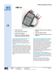
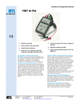
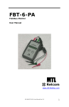
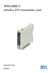
technical
technical datasheet
datasheet
fbt-6-PA
fieldbus diagnostic monitor
• fieldbus powered
• device add & drop indication
• shield short indication
• measures low, fieldbus and high
frequency average and peak noise
• measures signal level for all segment
devices
• assesses network health
• uploads measurement data to a PC
via USB port
The Profibus-PA Diagnostic Monitor, FBT6-PA, is used to examine the operation of a
live Profibus-PA segment without interfering
with its operation. The Monitor is intended
for maintenance personnel to verify segment
operation or to troubleshoot an errant
segment.
The FBT-6-PA Diagnostic Monitor checks
for retransmissions from each device on
the segment, providing a key performance
indicator of segment health. The Monitor also
provides measurements of bus voltage level,
device signal level, and peak and average
noise level. It displays the number of devices
present on the segment and indicates when
devices are added or removed from the
segment. It also detects the presence of a
short between either of the signal wires and
the cable shield.
Modern
fieldbus
commissioning
procedures require various bus parameters
to be measured and recorded. Key
parameters include bus voltage, signal
level for each device and noise level on
EPS FBT6PA RevF 040613
www.mtl-inst.com
[email protected]
each segment or at every device on each
segment. Recording the results allows a
baseline of the fieldbus physical layer to be
established. The Monitor collects this data,
and saves up to eight segment reports to be
saved for transfer to a PC via a USB port.
The reports are saved as Microsoft® Excel
files as a comprehensive commissioning
and operations report. Considerable savings
can be achieved by reducing commissioning
time and verifying the correct operation of
the segment.
Data
collected
from
periodic
segment verification testing or during
troubleshooting can be simply transferred
to a file for easy comparison to the segment
baseline/history measurements. Data can
be displayed as tables and graphs using
Microsoft® Excel.
Hand-held for portability, the Monitor is
powered by the fieldbus so that no battery or
external power source is required. It includes
colour- coded test leads and an LCD display.
OPERATION
The FBT-6-PA is connected to the segment using the clip-on probes at
the end of the cable. The red probe is connected to the fieldbus + wire,
the black probe to the – wire and the green probe to the shield wire.
The + and – test leads are polarity sensitive and the Monitor will not
operate if they are reversed.
When first connected to a fieldbus, a version number is displayed
for several seconds. The Monitor then performs a Segment Check
providing a quick indication of segment health.
The “FUNCTION” and “SELECT” buttons are used to choose from
segment parameters that can be examined with the Monitor. When
a function is selected, the data portion of the LCD display is blank
until the Monitor has collected and processed the data. After that, the
measured value is shown. The indication “OK” is shown if the measured
value is within the acceptable range. The indication “BAD” is shown if
the measured value is outside of the acceptable range.
The rotating symbol in the lower right corner of the display indicates
that there is segment activity. A horizontal bar (underscore) under the
rotating symbol indicates that a frame was detected, but could not be
decoded. This is not a maintained function, so if a single “bad” frame
is detected, the underscore will only display for a short time. Periodic
“bad” frames will cause the underscore to blink. The following are more
detailed explanations of each of the Monitor’s functions.
button. The first device shown will be the Master. By default,
measurements greater than 150mV are OK. If a device leaves the
segment, a “-” is displayed; if a device is added it shows “+”.
Average Noise
Displays the average of the most recent 100 noise measurements.
Noise levels are measured and displayed in 3 frequency bands:
frequencies in the fieldbus signalling band (Fieldbus Frequency, FF),
frequencies below the fieldbus signalling band (Low Frequency, LF)
and frequencies above the fieldbus signalling band (High Frequency,
HF). The particular frequency band displayed is selected by pushing
the “SELECT” button.
Peak Noise
Displays the peak noise recorded since the Monitor was connected.
The value displayed is the highest noise level measured since the last
reset. Peak noise levels are measured and displayed in the same three
frequency bands as average noise.
Segment Check
When first connected, the FBT-6-PA gathers data for all of its monitoring
functions. If all measured data is within acceptable range, the Monitor
displays “ALL MEASUREMENTS OK”.
Voltage
The DC voltage on the segment is shown. By default, measurements
over 9 volts are OK. The maximum input voltage is 32.0 volts.
Device Count
If Profibus PA devices are active on the segment, the Monitor counts
them. If the count has remained the same since the initial segment
check was performed, the display shows “OK”. Note, on Profibus PA
segments, the Master is considered a device and, as such, is included
in the count.
The FBT-6-PA is more sensitive to missed communications than most
PC monitoring software. As a result, a device may still show up on
PC monitoring software, even though the FBT-6-PA has removed
the device from its internal list of active devices. Devices having
communication difficulties may show up on the FBT-6-PA as repeatedly
being added or dropped.
If a device leaves the segment, the display shows “-”; if a new device
is added it shows “+”.
Device
The address (in decimal and hexadecimal) and signal level of each
device on the segment is displayed in turn by pushing the “SELECT”
Retransmit
If a device does not respond to a request frame or a token frame, the
frame is retransmitted. The FBT-6-PA indicates the address (decimal
and hexadecimal) of the last device that failed to respond, together with
the number of retransmits since the function was reset. If more than
250 retransmits are detected, the display will read “250+”. Pressing
the “SELECT” button cycles through screens indicating the number of
detected retransmits for each device.
Shield Short
If a short circuit between the + fieldbus wire and the cable shield is
detected, “(+) TO SHIELD SHORT” is displayed. If the short is between
the – wire and the shield, “(–) TO SHIELD SHORT” is displayed.
If a detected shield short goes away the Monitor indicates an
INTERMITTENT SHIELD SHORT to (+) or (-).
Add–Drop
If a new device is added to the segment, the Monitor will display its
address and signal level. If a frame is retransmitted to a device, the
device is considered “dropped” by the FBT-6-PA and the Monitor will
display the address and last known signal level of the dropped device.
A Master device that is sent an FDL Status Request frame is also
considered dropped.
Low
The signal level of the device with the weakest signal is shown. The
device’s address (in decimal and hexadecimal) is also displayed. This
will be the lowest signal level reading from a device since the Monitor
was connected to the fieldbus. By default, measurements greater than
150mV are OK.
The given data is only intended as a product description and should not be regarded as a legal warranty of properties or guarantee. In the interest of further technical developments, we reserve the right to make design changes.
EUROPE (EMEA): +44 (0)1582 723633
THE AMERICAS: +1 800 835 7075
ASIA-PACIFIC: +65 6645 9888
[email protected]
[email protected]
[email protected]
EPS FBT6PA RevF 040613
Save Report
Saves the data collected by the Monitor as a report. Up to 8 reports
may be saved from multiple segments and/or multiple locations on one
segment.
Transfer Report
Connect the Monitor to a PC USB port and transfer the saved reports
to Excel files on the PC.
Set Report Names
Customize the names of the reports saved in the Monitor to easily
identify the report source.
Set OK/BAD Limits
Change the limits at which Monitor measurements transition from OK
to BAD to establish customized plant standards.
SPECIFICATIONS
Input voltage
Fieldbus Mode: 8 to 32 VDC
USB Mode: 4.1 to 5.5 VDC
Input current
Fieldbus mode: 10mA max.‡
USB mode: 30mA max.
Power dissipation
Fieldbus mode: 320mW max. (@ 32 VDC)
USB mode: 165mW max. (@ 5.5 VDC)
Operating Temperature
–20 to +50°C *
Dimensions
146 x 88 x 28 mm (5.7 x 3.5 x 1.1 inches)
Weight
378g (0.83lb)
Case Material
ABS
DC Voltage measurement range
8 to 32 ± 0.5 VDC
Signal level measurement range
0.12 to 2 Vpp ±10% ± 25mVpp
Noise measurement ranges
LF (50Hz to 4kHz): 0 to 1000 mVpp ±15% ± 25 mVpp
FF (9kHz to 40kHz): 0 to 1000 mVpp ±10% ± 25 mVpp †
HF (90kHz to 350kHz): 0 to 250 mVpp ±20% ± 25mVpp
Software utility and drivers
Operating systems: Windows XP, Windows Vista and Windows 7
USB versions: 1.1 & 2.0
Windows is a registered trademark of Microsoft Corporation
(Note: Vpp = Volts peak-to-peak)
‡
*
†
In fieldbus mode the FBT-6-PA is powered by the fieldbus and draws
approximately 9.4mA of current from the segment (depending on bus
voltage and ambient temperature).
Display update speed is impaired below –10°C
Excessive noise adjacent to the fieldbus frequency (FF) band will prevent
the FBT-6-PA from reading the fieldbus data and thus reduce functionality.
The given data is only intended as a product description and should not be regarded as a legal warranty of properties or guarantee. In the interest of further technical developments, we reserve the right to make design changes.
EUROPE (EMEA): +44 (0)1582 723633
THE AMERICAS: +1 800 835 7075
ASIA-PACIFIC: +65 6645 9888
[email protected]
[email protected]
[email protected]
EPS FBT6PA RevF 040613
approvalS
Region
(Authority)
Standard
US (FM)
3600, 3610, 3611, 3810
ANSI/ISA 60079-0:2009
ANSI/ISA 60079-11:2009
Certificate
Approved For
Ratings
3023564
Class I, Div 2, ABCD, T4
Class I, Zone 2, IIC T4
Vmax(V)
Imax Gps A, B/IIC (mA)
Imax Gps C, D/IIB,IIA (mA)
NIFW
32
1500
1500
FNICO
17.5
274
570
US (FM)
3600, 3610, 3611, 3810
ANSI/ISA 60079-0:2009
ANSI/ISA 60079-11:2009
3023564
Class I, Div 1, ABCD, T4
Class I, Zone 0 and 1,
AEx ia IIC T4
Vmax(V)
Imax Gps A, B/IIC (mA)
Imax Gps C, D/IIB,IIA (mA)
Pi(W)
Entity IS
24
250
250
1.2
FISCO
17.5
183
380
5.32
Canada (FM)
C22.2 No. 213,
C22.2 No. 157
CAN/CSA-E79-0-95,
CAN/CSA-E79-11-95
3028840
Class I, Div 2, ABCD, T4
Class I, Zone 2, IIC T4
Vmax(V)
Imax Gps A, B/IIC (mA)
Imax Gps C, D/IIB,IIA (mA)
NIFW
32
1500
1500
FNICO
17.5
274
570
Canada (FM)
C22.2 No. 213,
C22.2 No. 157
CAN/CSA-E79-0-95,
CAN/CSA-E79-11-95
3028840
Class I, Div 1, ABCD, T4
Class I, Zone 0 and 1,
Ex ia IIC T4
Vmax(V)
Imax Gps A, B/IIC (mA)
Imax Gps C, D/IIB,IIA (mA)
Pi (W)
Entity IS
24
250
250
1.2
FISCO
17.5
183
380
5.32
EU (LCIE)
EN60079-0:2009*
EN60079-11:2007*
EN60079-27:2008*
LCIE06ATEX6111X
E II 1 G Ex ia lIC T4
Ui (V)
Ii (mA)
Pi (W)
Entity IS
24
250
1.2
FISCO
17.5
380
5.32
EU (Relcom)
EN60079-0:2009
EN60079-11:2007
EN60079-15:2010
RELC07ATEX1003X
E II 3 G
IECEx
IEC60079-0:2004
IEC60079-11:2006
IEC60079-27:2005-04
Entity IS
24
250
1.2
FISCO
17.5
380
5.32
IECEx FME 08.0003X
Ex ic IIC T4 Gc
Vmax = 32V, Imax = 1.5A
Ex ia lIC T4
Ex ic lIC T4
Ui (V)
Ii (mA)
Pi (W)
Ex ic
32
1500
NA
* the original LCIE Certificate used earlier standards. We have determined that there are no technical differences (affecting the products) between those
standards and the currently harmonized EN standards listed above.
ordering information
Part Number
Description
FBT-6-PA
Profibus PA Diagnostic Monitor supplied in carrying case with FBT-A61,
-A62, and -A63 cables, software and instruction manual.
Picture
FBT-A61
FBT-6-PA Fieldbus Cable with Mini-Hook Probes
FBT-A62
FBT-6-PA USB Cable
FBT-A63
FBT-6-PA Fieldbus Cable with Clip-on Probe
FBT-A64
Clip-on Probe
501-366
FBT-6-PA User Manual
The given data is only intended as a product description and should not be regarded as a legal warranty of properties or guarantee. In the interest of further technical developments, we reserve the right to make design changes.
EUROPE (EMEA): +44 (0)1582 723633
THE AMERICAS: +1 800 835 7075
ASIA-PACIFIC: +65 6645 9888
[email protected]
[email protected]
[email protected]
EPS FBT6PA RevF 040613