1
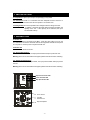
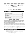
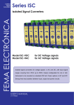
“BULL POWER”
Line Conditioner
Regulating Power Bar
Auto Voltage Regulation
User’s Manual
TABLE OF CONTENTS
INTRODUCTION……………………………………………………………………………….. 1
1. IMPORTANT SAFETY INSTRUCTIONS ……………………………………………..……….. 2
2. PRESENTATION………………...……………………………..…,.……………………….. 2
3 . I NSTALLATION… … … … … … … … … … … … … … … … … … . . . … … … … … … … … … … … . 3
4. OPERATION……………………………………………………...………………………… 3
A PPENDIX A T R O U B L E S H O O T I N G … … … … … … … … … … … … … … . . . … … … … … … … … . . 4
APPENDIX B. SPECIFICATIONS ……..………………………………………..………………. 4
Please read and save this manual!
Thank you for selecting this Bull Power Line Conditioner. It provides you with a high degree of protection for
your connected equipment. The manual is a guide to installing and using the Bull. It includes important
safety instructions for operation and correct installation . If you should have any problem, please refer to this
manual before calling customer service.
-1-
1. IMPORTANT SAFETY INSTRUCTIONS
? WARNING (SAVE THESE INSTRUCTIONS): This manual contains important
instructions that should be
followed during installation and
maintenance .
? WARNING (Controlled Environment): Intended for installation in a controlled
environment.
? CAUTION: Risk of electric shock, do not remove cover. No user serviceable parts
inside. Refer servicing to qualified service personnel.
? CAUTION: Avoid exposure to direct sunlight, stoves or any other heat source.
? CAUTION: To prevent overheating, make sure that the ventilation openings of the
unit are not covered.
? CAUTION: Keep moisture and dust away.
2. PRESENTATION
The Bull Power Line Conditioner can provide you with microprocessor controlled
Automatic Voltage Regulation . It can supply you with pure, stable power and
eliminate the damage caused by power problems.
Step Down Indicator LED
Illuminated when Utility input is HIGH and Voltage Regulator
is STEPPING DOWN the voltage.
Power Indicator LED
Illuminated when power switch is ON and utility is PRESENT
Step Up Indicator LED
Illuminated when utility input is LOW and Voltage Regulator
is STEPPING UP the voltage
No indicators will be illuminated if:
1. Power Switch is in OFF position.
2. Circuit Breaker has tripped due to an overload or short circuit.
3. No utility power is present.
-2-
3. INSTALLATION
3.1 Inspection: Inspect upon receipt. The packaging is recyclable.
3.2 Placement: Install in a controlled area with adequate air flow and free of
excessive dust. Do not operate in an outdoor area.
3.3 Utility Power: Be sure the polarities a nd voltage match the rating of the unit.
In addition, check that the loads being protected are within the
capacity of the unit. If the capacity is not sufficient, the input
circuit breaker will trip.
4. OPERATION
4.1 Switch on:
When utility power is connected to the BULL, press the “ON” button to turn on the
unit. After that, connect the electrical cords of the equipment that will be used (such
as computer or monitor) to the rear panel of AVR unit.
4.2 Switch off:
Press the “OFF” button to turn off .
4.3 “Over load Protection”
When the unit is overloaded , the input power breaker will trip to protect the unit .
Warning: Once the circuit breaker has tripped, please wait 60 sec before resetting.
4.4 “Output short Protection”
When there is a short in the output loads , the input power breaker will trip to protect
the unit .
Warning: Once the circuit breaker has tripped, please wait 60 sec before resetting.
Step Down Indicator LED
Power Indicator LED
Step Up Indicator LED
Power Switch
Tel & Net
Protection Port
Output Receptacle
-3-
APPENDIX A . TROUBLESHOOTING
PROBLEM
POSSIBLE CAUSE
ACTION TO TAKE
Cannot be turned ON/OFF SWITCH is in the off Press the ON/OFF SWITCH to the
on
position
On position
Circuit breaker has tripped
Reset the circuit breaker
APPENDIX B . SPECIFICATIONS
INPUT
OUTPUT
PROTECTION
PHYSICAL
Voltage
Frequency
Voltage
Capacity
Frequency
Overload
Short Circuit
Transient Suppression
Modem / Network
Number of Outlets
Net Weight Kg (lbs)
Dimensions (mm) W x D x H
120Vac +/- 30% (80-150Vac)
50 or 60 Hz
120Vac +/- 10% (108-132Vac)
2000VA / 1000Watts
50 or 60 Hz
Breaker
Breaker
150V Clamping Voltage
5700 Joules
20,000 Amps
< 1 nano second response
RJ11 / RJ45
6
1.6 (3.52)
123 x 136 x 102
©2002. Jan 31 Version. 1.1 All right Reserved.
All trademarks are property of their respective owners. Specifications subject to change without
prior notice.
-4-