1
Crane Management System (CMS)
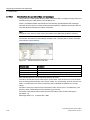
___________________
Preface
1
___________________
Product group
SIMOCRANE
Crane Management System (CMS)
2
___________________
Functions of CMS
3
___________________
Remote CMS (RCMS)
Assigning parameters and
4
___________________
addressing
5
___________________
Planning and configuring
System Manual
Administering hardware and
6
___________________
software
7
___________________
Time synchronization
8
___________________
Service and maintenance
A
___________________
Appendix
Valid for version 4.1 SP1
03/2011
Legal information
Legal information
Warning notice system
This manual contains notices you have to observe in order to ensure your personal safety, as well as to prevent
damage to property. The notices referring to your personal safety are highlighted in the manual by a safety alert
symbol, notices referring only to property damage have no safety alert symbol. These notices shown below are
graded according to the degree of danger.
DANGER
indicates that death or severe personal injury will result if proper precautions are not taken.
WARNING
indicates that death or severe personal injury may result if proper precautions are not taken.
CAUTION
with a safety alert symbol, indicates that minor personal injury can result if proper precautions are not taken.
CAUTION
without a safety alert symbol, indicates that property damage can result if proper precautions are not taken.
NOTICE
indicates that an unintended result or situation can occur if the corresponding information is not taken into
account.
If more than one degree of danger is present, the warning notice representing the highest degree of danger will
be used. A notice warning of injury to persons with a safety alert symbol may also include a warning relating to
property damage.
Qualified Personnel
The product/system described in this documentation may be operated only by personnel qualified for the specific
task in accordance with the relevant documentation for the specific task, in particular its warning notices and
safety instructions. Qualified personnel are those who, based on their training and experience, are capable of
identifying risks and avoiding potential hazards when working with these products/systems.
Proper use of Siemens products
Note the following:
WARNING
Siemens products may only be used for the applications described in the catalog and in the relevant technical
documentation. If products and components from other manufacturers are used, these must be recommended
or approved by Siemens. Proper transport, storage, installation, assembly, commissioning, operation and
maintenance are required to ensure that the products operate safely and without any problems. The permissible
ambient conditions must be adhered to. The information in the relevant documentation must be observed.
Trademarks
All names identified by ® are registered trademarks of the Siemens AG. The remaining trademarks in this
publication may be trademarks whose use by third parties for their own purposes could violate the rights of the
owner.
Disclaimer of Liability
We have reviewed the contents of this publication to ensure consistency with the hardware and software
described. Since variance cannot be precluded entirely, we cannot guarantee full consistency. However, the
information in this publication is reviewed regularly and any necessary corrections are included in subsequent
editions.
Siemens AG
Industry Sector
Postfach 48 48
90026 NÜRNBERG
GERMANY
Ⓟ 03/2011
Copyright © Siemens AG 2009.
Technical data subject to change
Preface
Product brief
This document is part of the SIMOCRANE CMS product package. It describes the design
and functionality of SIMOCRANE CMS based on SIMATIC WinCC and the SIMOCRANE
CMS add-on package for adding specific crane management system functions to SIMATIC
WinCC.
SIMOCRANE CMS provides the basis for realizing information systems locally for the crane
(CMS) and centrally for the plant (RCMS). These systems assist the user in operation and
troubleshooting.
The scope of functions offered by SIMOCRANE CMS include:
● Graphic visualization of the crane at CMS level and a graphic overview of the entire plant
at RCMS level
● Alarm/event system and support for diagnostics
● Recording measured values for various operating parameters
● Recording and analysis of cargo handling data
● Recording and analysis of operating hours and counters
● Process data interfaces to various automation systems
● Standard interfaces to higher-level logistics systems
● Data transfer between CMS stations and an RCMS server
● Analysis of operational data as well as recording and analysis of downtimes at RCMS
level
The user interfaces at CMS and RCMS level are structured with a focus on user groups and
offer various users the corresponding information and functions for their respective area of
work.
As a basis for configuring a CMS station, two standard applications are supplied for the CMS
and RCMS levels in the CMS add-on package. The standard application includes the
functions of the crane management system described above. This document describes how
the standard applications can be adapted to various project requirements.
Demarcation
SIMOCRANE CMS provides various tools for implementing the CMS functionality required. It
is not a ready-to-run crane management system.
Crane Management System (CMS)
System Manual, 03/2011
3
Preface
Area of application
The system is designed for use on cranes and for harbour and industrial environments. The
SCADA product used allows the adaptation to various applications. Thanks to its scalability,
anything from CMS single-user systems right through to networked CMS infrastructures can
be installed.
Content
The document provides information on the following areas:
Target groups and level of knowledge
This document addresses various target groups. For these target groups, the following
knowledge is required:
• Sales & Marketing
General knowledge about the scope of the WinCC function
• Engineering
Good knowledge of WinCC
• Commissioning
supervisors
Good knowledge of WinCC
Products / product combinations
The SIMOCRANE CMS WinCC add-on, the standard application supplied, and the
supplementary WinCC options will be introduced with regard to different areas of use.
Functionality
The document describes the scope of functions of SIMOCRANE CMS.
In addition to single-user systems for one CMS station on a crane, multi-user topologies and
RCMS options are also described. The RCMS options contain information about remote
access to a CMS station and installation of an RCMS server.
Assigning parameters and addressing
In a few simple steps, you can start the standard application in your own environment, make
default settings or enter project-specific data (messages, operational data, ... ). Various
controllers can be connected to WinCC.
Configuring
Using standard WinCC tools and settings in the CMS Editor, the standard application can be
adapted to different project preconditions.
Administration of hardware
PCs or other display devices form the basis of the operator stations. Software must be
installed depending on the application.
Interfaces
The interface between the CMS application and the crane controller is described in detail.
Style guide
The CMS standard application has been created in accordance with certain design points
and configuration guidelines. These should simplify project-specific expansions of the
standard application.
Crane Management System (CMS)
4
System Manual, 03/2011
Preface
Document structure
Different chapters of the document will be of interest to different target groups. Each chapter
starts with a summary of its main content.
All chapters featuring work instructions for the reader are split into three sections:
● Initial situation:
What functions/configurations are existing (in the CMS standard application, WinCC, PC,
etc.)?
● Processing steps / operator actions:
What processing steps need to be performed to adapt the initial situation to other
requirements?
● Result:
What are the impacts of the changes?
Additional information
Technical Support
If you have any technical questions, please contact our hotline (worldwide):
Phone: +49 (180) 50 50 222
Fax: +49 (180) 50 50 223
Internet: http://www.siemens.de/automation/support-request
Siemens Internet addresses
You can find information about crane solutions on the Internet at
http://www.siemens.com/cranes
You can find information about SIMOCRANE products, product support and FAQs on the
Internet at http://support.automation.siemens.com/WW/view/en/10807397/130000
Additional support
We also offer courses to help you familiarize yourself with SIMOCRANE and its principle
operation. To do this, please contact your local Siemens sales office.
If you have any questions about crane applications, please send an e-mail to the following
address:
applications.cranes.aud @siemens.com
Crane Management System (CMS)
System Manual, 03/2011
5
Preface
Crane Management System (CMS)
6
System Manual, 03/2011
Contents
Preface ...................................................................................................................................................... 3
1
2
Product group .......................................................................................................................................... 11
1.1
Product structure..........................................................................................................................11
1.2
SIMATIC WinCC ..........................................................................................................................12
1.3
SIMOCRANE CMS add-on package ...........................................................................................13
1.4
SIMOCRANE CMS standard application.....................................................................................13
1.5
1.5.1
1.5.2
1.5.3
1.5.4
1.5.5
1.5.6
SIMATIC WinCC options and certified add-ons...........................................................................14
SIMATIC WinCC / Web Navigator ...............................................................................................14
WinCC / Data Monitor ..................................................................................................................14
WinCC / Downtime Monitor..........................................................................................................15
WinCC server...............................................................................................................................15
Certified system diagnostics add-on............................................................................................15
Certified PM-Maint add-on ...........................................................................................................16
1.6
SIPLUS CMS ...............................................................................................................................16
Functions of CMS .................................................................................................................................... 17
2.1
2.1.1
2.1.2
2.1.3
System design..............................................................................................................................17
Applications..................................................................................................................................17
Topology ......................................................................................................................................18
Communications with the control level ........................................................................................19
2.2
Design of user interface ...............................................................................................................20
2.3
User groups..................................................................................................................................23
2.4
Condition monitoring ....................................................................................................................24
2.5
Process control ............................................................................................................................27
2.6
2.6.1
2.6.2
2.6.3
2.6.4
2.6.5
Fault diagnostics ..........................................................................................................................29
Message lists ...............................................................................................................................29
Message statistics........................................................................................................................31
Maintenance instructions and guidelines.....................................................................................32
References to additional information ...........................................................................................33
Web-based diagnostics of components.......................................................................................34
2.7
2.7.1
2.7.2
2.7.3
Operational data ..........................................................................................................................35
Recording operational data..........................................................................................................35
Cargo handling data.....................................................................................................................35
Load and operating hours counter...............................................................................................37
2.8
2.8.1
2.8.2
2.8.3
Reporting......................................................................................................................................38
WinCC report system...................................................................................................................38
WinCC/Data Monitor for the CMS station ....................................................................................39
Output formats and interfaces......................................................................................................40
2.9
Recording process values............................................................................................................41
Crane Management System (CMS)
System Manual, 03/2011
7
Contents
2.9.1
2.9.2
2.9.3
2.9.4
3
4
Applications................................................................................................................................. 41
WinCC standard process value archiving ................................................................................... 41
WinCC standard process value archiving with increased resolution .......................................... 41
CMS Fast-Trace – SIPLUS CMS ................................................................................................ 42
Remote CMS (RCMS) ............................................................................................................................. 47
3.1
RCMS topology ........................................................................................................................... 49
3.2
CMS-RCMS data transfer ........................................................................................................... 50
3.3
Design of user interface .............................................................................................................. 51
3.4
3.4.1
3.4.2
Terminal overview ....................................................................................................................... 53
Cartographic display ................................................................................................................... 53
Tree view and statistics............................................................................................................... 54
3.5
Fault diagnostics ......................................................................................................................... 56
3.6
Operational data and performance analysis ............................................................................... 57
3.7
Remote access ........................................................................................................................... 60
Assigning parameters and addressing..................................................................................................... 61
4.1
4.1.1
4.1.2
4.1.3
4.1.4
4.1.4.1
4.1.4.2
4.1.4.3
4.1.4.4
4.1.4.5
4.1.4.6
4.1.5
4.1.6
4.1.7
4.1.7.1
4.1.7.2
4.1.7.3
4.1.7.4
4.1.7.5
4.1.7.6
4.1.7.7
4.1.7.8
4.1.7.9
4.1.7.10
4.1.8
4.1.8.1
4.1.8.2
4.1.8.3
4.1.8.4
4.1.9
4.1.10
4.1.10.1
CMS station................................................................................................................................. 61
Starting the CMS Runtime automatically .................................................................................... 61
Settings in WinCC ....................................................................................................................... 61
Communication between the CMS station and the crane controller........................................... 64
Default settings in the standard application ................................................................................ 66
"General" tab ............................................................................................................................... 68
"Hoist" tab.................................................................................................................................... 69
"Trolley" tab ................................................................................................................................. 70
"Boom-hoist" tab ......................................................................................................................... 71
"Gantry" tab ................................................................................................................................. 72
"Slewing gear" tab....................................................................................................................... 73
CMS topology.............................................................................................................................. 73
CMS system tags ........................................................................................................................ 80
Alarm/event system for the CMS station..................................................................................... 81
Message procedures................................................................................................................... 81
Message blocks .......................................................................................................................... 81
Message classes and message types ........................................................................................ 83
Group messages......................................................................................................................... 84
Archive configuration................................................................................................................... 87
Message import in the WinCC Alarm Logging ............................................................................ 88
Maintenance instructions in the CMS configuration editor.......................................................... 88
Remarks on maintenance instructions........................................................................................ 91
References in the CMS editor ..................................................................................................... 92
References according to STEP 7................................................................................................ 98
Operational data on the CMS station........................................................................................ 103
Data sets for configuring operational data ................................................................................ 103
Acquiring cargo handling data .................................................................................................. 105
Recording time slices for counter values .................................................................................. 109
Recording MMBF data .............................................................................................................. 112
Integrating web-based documentation...................................................................................... 114
Communication with the RCMS server ..................................................................................... 115
Set up communication............................................................................................................... 115
Crane Management System (CMS)
8
System Manual, 03/2011
Contents
5
4.1.10.2
4.1.10.3
4.1.10.4
4.1.10.5
Data interface for operational data and messages ....................................................................116
Transferring messages ..............................................................................................................118
Transferring operational data.....................................................................................................119
Transferring tag values ..............................................................................................................121
4.2
4.2.1
4.2.2
4.2.3
Configuring the CMS Trace Viewer ...........................................................................................122
Scope of functions of the Trace Viewer .....................................................................................123
Information for configuring in X-Tools........................................................................................125
Installing and configuring the Trace Viewer...............................................................................127
4.3
Setting up remote access ..........................................................................................................131
4.4
4.4.1
4.4.1.1
4.4.1.2
4.4.2
4.4.3
4.4.4
4.4.5
4.4.5.1
4.4.5.2
4.4.6
4.4.7
4.4.8
4.4.8.1
4.4.8.2
4.4.8.3
4.4.9
4.4.9.1
4.4.9.2
4.4.9.3
4.4.9.4
4.4.9.5
4.4.9.6
4.4.9.7
RCMS server..............................................................................................................................135
Principles of data transfer ..........................................................................................................136
Transferring configuration data ..................................................................................................137
Transfer of runtime data.............................................................................................................138
Starting the CMS Runtime automatically ...................................................................................140
Settings in WinCC......................................................................................................................140
Tag management.......................................................................................................................141
Message system of the RCMS server .......................................................................................143
WinCC Alarm Logging ...............................................................................................................143
Additional information ................................................................................................................146
Operational data of the RCMS server........................................................................................147
RCMS topology ..........................................................................................................................149
Communication between the RCMS server and the CMS stations ...........................................152
Generation of configuration data (upload) .................................................................................153
Synchronizing configuration data...............................................................................................158
Runtime data transfer ................................................................................................................159
Downtime Monitor project ..........................................................................................................160
Integration of the DTM project ...................................................................................................162
Time model and status word......................................................................................................163
Counters.....................................................................................................................................165
Algorithms ..................................................................................................................................166
Changing or adding a crane.......................................................................................................167
Save configuration for KPI Control.............................................................................................169
Saving the DTM project .............................................................................................................173
Planning and configuring ....................................................................................................................... 175
5.1
5.1.1
5.1.2
5.1.3
5.1.4
5.1.5
5.1.6
5.1.7
5.1.8
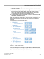
Expansion of visualization and screen structure........................................................................175
Overview of screen structure and screen navigation.................................................................175
Navigation bar ............................................................................................................................178
Inserting a new menu at the primary level .................................................................................179
Screen initialization ....................................................................................................................182
Group fault bar ...........................................................................................................................182
Message filters ...........................................................................................................................186
Additional message information in the CMSFaults control ........................................................187
Integrate the tree view into the RCMS application.....................................................................190
5.2
5.2.1
5.2.2
User groups................................................................................................................................193
Changing passwords .................................................................................................................194
Automatic user log-off ................................................................................................................194
5.3
5.3.1
5.3.2
Languages .................................................................................................................................196
Standard application languages.................................................................................................196
Language-dependent texts in screens.......................................................................................196
Crane Management System (CMS)
System Manual, 03/2011
9
Contents
6
7
8
A
5.3.3
Language-dependent message texts........................................................................................ 198
5.4
Mass data configuration in WinCC............................................................................................ 200
Administering hardware and software.................................................................................................... 201
6.1
PC configuration of the CMS station......................................................................................... 201
6.2
PC configuration of the web client station................................................................................. 205
6.3
Trace recorder........................................................................................................................... 205
6.4
6.4.1
6.4.2
PC configuration of the RCMS server....................................................................................... 206
RCMS server............................................................................................................................. 206
RCMS operator station.............................................................................................................. 207
6.5
6.5.1
6.5.2
User administration ................................................................................................................... 208
Information for Windows users ................................................................................................. 208
Automatic user logon in Windows............................................................................................. 208
Time synchronization............................................................................................................................. 211
7.1
CMS station – controller ............................................................................................................ 211
7.2
PC time synchronization ........................................................................................................... 211
Service and maintenance ...................................................................................................................... 213
8.1
8.1.1
8.1.2
8.1.3
Checking the data volume......................................................................................................... 213
Buffer for XML files.................................................................................................................... 213
Limitation of the used disk space.............................................................................................. 213
Log files ..................................................................................................................................... 214
8.2
8.2.1
8.2.2
8.2.3
Data archiving and backup........................................................................................................ 215
Backup of WinCC messages .................................................................................................... 215
Backup of WinCC process values............................................................................................. 215
Backup of user data in the CMS editor ..................................................................................... 215
Appendix................................................................................................................................................ 217
A.1
A.1.1
A.1.2
A.1.3
A.1.4
A.1.5
A.1.6
A.1.7
Design guidelines...................................................................................................................... 217
Introduction ............................................................................................................................... 217
Screen design and layout.......................................................................................................... 217
Navigation ................................................................................................................................. 218
Color scheme ............................................................................................................................ 219
Naming conventions.................................................................................................................. 220
Code conventions ..................................................................................................................... 222
Conventions for the screen structure ........................................................................................ 223
A.2
Bibliography .............................................................................................................................. 223
Crane Management System (CMS)
10
System Manual, 03/2011
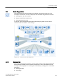
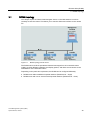
1
Product group
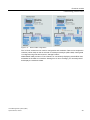
This chapter describes the fundamental product structure of SIMOCRANE CMS. This
chapter is therefore mainly aimed at people working in project planning, i.e. people who have
to define a crane management system for specific project requirements.
1.1
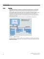
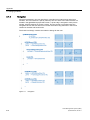
Product structure
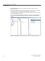
SIMOCRANE CMS is not a ready-to-run crane management system. SIMOCRANE CMS
provides various tools for implementing the CMS functionality required. The CMS standard
application supplied already covers a high level of functionality and is therefore a good
starting point for quickly realizing customer-specific solutions.
Figure 1-1
Product structure of SIMOCRANE CMS
Crane Management System (CMS)
System Manual, 03/2011
11
Product group
1.2 SIMATIC WinCC
1.2
SIMATIC WinCC
The SIMATIC WinCC software forms the core for the SIMOCRANE CMS crane management
system.
The basic WinCC software offers the most important functions of a SCADA system
encountered in crane applications.
● User administration:
Issuing and checking user access rights both for configuration and the runtime
environment. As of WinCC V7, SIMATIC Logon is part of the basic WinCC software.
SIMATIC Logon integrates itself into the security system and the user administration of
Windows.
● Visualization:
The basic WinCC software assists with the configuration of individual user interfaces
through the provision of standard objects. This includes, for example, simple standard
objects such as lines or rectangles, common graphic objects, buttons and input/output
fields, picture windows, OLE objects,and ActiveX Controls.
● Alarm/event system:
The alarm/event system records process messages and local events and archives them
in cyclic archives. The archived messages are displayed in an ActiveX Control. The type
of message procedure and archiving can be configured.
● Process value archiving:
Historical values and value patterns are saved in process value archives. The type of
recording and archiving can be configured.
● Protocol system:
The protocol system is used to save or print data from WinCC in fixed layouts as files.
● Configuration of mass data:
WinCC projects can be edited in MS Excel using an extra tool.
Since WinCC is commonly used as a standard product, support and expertise are widely
available across the world. WinCC provides integrated data archiving for messages and
process values on the basis of MS SQL Server. Other benefits of WinCC include scalability,
expandability, and transparency.
Scalability
SIMATIC WinCC can be used to configure anything from single-user systems right through
to networked structures. The topology can be extended for various crane system
requirements.
Expandability
Thanks to its modular software structure and open interfaces, the basic system can be
adapted to the various requirements of a crane system using the WinCC options or add-ons.
Crane Management System (CMS)
12
System Manual, 03/2011
Product group
1.3 SIMOCRANE CMS add-on package
Transparency
Different communication channels, based on protocols used around the world such as
TCP/IP, PROFIBUS or OPC, not only allow for connection to SIMATIC S7 controllers, but
also connection to controllers of other well-known manufacturers. The open interfaces allow
for connection to higher-level systems and the development of dedicated applications.
1.3
SIMOCRANE CMS add-on package
The SIMOCRANE CMS add-on package adds crane-specific requirements to the WinCC
basic system.
The add-on package includes an editor, which is integrated into WinCC Explorer once the
add-on package has been installed, and a runtime component (CMS Runtime). Graphic
controls are provided in the WinCC Graphics Designer.
In the editor, parameters can be set for the functions of the CMS add-on package for various
crane applications which are performed by the CMS Runtime.
The add-on package offers the following functions:
● It expands WinCC Alarm Logging by the option of saving additional information about
messages and displaying them in runtime in the graphic controls.
● The "PLC reference" function enables users to jump to the STEP 7 editor (STEP 7
installation required).
● Event-controlled recording of operational data (cargo handling data, counters) from the
crane controller
● Data transfer (operational data, messages, and values of the WinCC tags) between CMS
stations and an RCMS server. As well as runtime data, configuration data is also
exchanged to make it easier to configure an RCMS server.
● Tree view of individual cranes in a terminal view to select a crane in order to view its
acquired data on the RCMS server.
● Import/export functions for configuring mass data
● Trace Viewer for displaying fast trace data (acquisition cycle < 500 ms).
1.4
SIMOCRANE CMS standard application
The CMS standard application is a WinCC project. The standard application uses the
functionality of SIMATIC WinCC and the SIMOCRANE CMS add-on, and therefore
represents a standard crane application. This combination of SIMATIC WinCC and
SIMOCRANE CMS add-on supports the following functions:
● Condition monitoring
● Fault diagnostics
● Recording operational data
Crane Management System (CMS)
System Manual, 03/2011
13
Product group
1.5 SIMATIC WinCC options and certified add-ons
● Reporting
● Integrating the Trace Viewer
The RCMS sample application includes an example of a plant view, the tree view of several
cranes, and examples for the analysis of operational data and downtimes.
1.5
SIMATIC WinCC options and certified add-ons
The options and add-ons described below are applied in various combinations to cover
additional functions.
1.5.1
SIMATIC WinCC / Web Navigator
The WinCC/Web Navigator extends CMS functionality by providing a remote-access option.
You can use the WinCC / Web Navigator to operate and observe a plant comprising various
stations via the Intranet or Internet. This does not require any changes to the WinCC project.
The Web Navigator is needed in the crane environment if
● remote access to the local CMS station is required (e.g. from the RCMS server).
● other HMI devices besides the electrical room PC are needed on the crane itself (crane
cabin, checker cabin).
The Web Navigator server is installed on the CMS station in the crane's electrical room. A
web navigator client can be setup on any Windows PC at the crane itself, at an RCMS server
or on other RCMS devices. The web client allows the WinCC project, running on the CMS
station, to be operated and visualized from MS Internet Explorer. Just like the WinCC basic
operator station, virtually all possible displays and operations are available to the web client.
1.5.2
WinCC / Data Monitor
The WinCC Data Monitor is an option for extended analysis of operational data and
messages from the WinCC archives.
The Data Monitor is particularly suited to use on the RCMS server. Here, the collected data
from all CMS stations connected to the RCMS server is available to the Data Monitor. You
can also use the Data Monitor on the CMS station if there is no RCMS server or none has
been planned.
Analysis results can be conveniently produced via Internet Explorer and published for other
users. Internet Explorer can be used to access this data on office PCs if the PC in question
has Internet or network access to the corresponding CMS station.
In addition to the options for data analysis, the Data Monitor also provides you with Web
Navigator sub-functions. The "Process Screens" offer a pure observing function for WinCC
screens. HMI devices which are only to be used for observation rather than operational
purposes do not therefore require a license for the Web Navigator.
Crane Management System (CMS)
14
System Manual, 03/2011
Product group
1.5 SIMATIC WinCC options and certified add-ons
1.5.3
WinCC / Downtime Monitor
The WinCC / Downtime Monitor can be used to record and analyze the behavior of the entire
crane system with regard to reducing the downtimes of single cranes. The Downtime Monitor
was originally developed for machine-oriented or line-oriented manufacturing plants but is
also easy to use in a crane environment. It is especially suited as application on the RCMS
server for analysis of the connected single cranes of a plant.
The Downtime Monitor helps to answer the following questions:
● What is the actual performance of a crane compared with the planned performance?
● How is load distributed over the cranes (where is there full load and where no-load
operation)?
● Why do comparable cranes constantly handle different numbers of standard containers
(TEU – Twenty-foot Equivalent Unit)?
The Downtime Monitor records downtimes and the reasons for them and calculates specific
parameters (KPI = Key Performance Indicators) so that terminal availability and productivity
can be increased in the future.
The shift calendar provided can also be used to include work shifts on the crane in the
analysis and to compare these with each other.
The system offers various display types for analysis results in WinCC Controls:
● Gantt chart for overview of operating states of different cranes in one overview or over
different periods.
● Bar charts or sub-divided bar charts, Pareto diagrams or trends for displaying the key
performance indicators such as availability, performance, MMBF, productivity (containers
per hour). The data can be grouped by type, period, or shift.
● Tables showing overview of plant states over different periods. The data can be printed
out or exported in csv format.
1.5.4
WinCC server
The WinCC client server topology is the right solution at RCMS level. One or more WinCC
servers act as a data collector for data from the connected CMS stations.
The servers support central operator stations as WinCC clients to which data from all cranes
is made available (RCMS operator stations).
1.5.5
Certified system diagnostics add-on
The system diagnostics provide visualization of the topology and field devices, and offer
detailed node diagnostics. This facility is integrated into WinCC, and is available for both
PROFIBUS and PROFINET.
The status of the CPU or I/O modules and the entire network can be visualized in clear
displays. Detailed pages for each module contain further information. The display is based
on the SIMATIC S7 conventions. Depending on the features of this add-on, a corresponding
block will need to be integrated into the S7 program for the purpose of data supply.
Crane Management System (CMS)
System Manual, 03/2011
15
Product group
1.6 SIPLUS CMS
Precise details of the functional scope and range of modules supported are contained in the
associated system description.
1.5.6
Certified PM-Maint add-on
The standard scope of the SIMOCRANE CMS package does not include a maintenance
planning system. It does, however, provide all the data this would require (e.g. operating
hours counter).
PM-MAINT is a sector- and technology-neutral tool for maintenance planning. PM-MAINT is
recommended if a project requires this type of functionality.
PM-MAINT must be installed on the RCMS server. PM-MAINT supports client views for the
operator stations of the RCMS servers.
PM-MAINT offers both calendar-controlled and event-controlled maintenance of components
on different single cranes. PM-MAINT therefore assists with the timely maintenance of
components in order to avoid the cost of premature maintenance or production outage and
downtimes.
An import and export function supports the process of configuring mass data.
1.6
SIPLUS CMS
SIPLUS CMS is a condition monitoring system. This allows data to be recorded with a data
point interval of less than 500 ms.
Crane Management System (CMS)
16
System Manual, 03/2011
Functions of CMS
2
This chapter provides an overview of the system design and main functions which the local
CMS provides. Several sections list various ways of implementing a functionality which may
be used depending on the project requirements.
2.1
System design
2.1.1
Applications
The CMS station is located at the crane. It can be operated as a single-user station (singleuser CMS); however, it also permits combined operation of a CMS station in the electrical
room with several client stations, for example, in the crane cabin or in the checker cabin
(multi-user system).
Figure 2-1
CMS as a single-user station in the crane cabin
Figure 2-2
CMS multi-user system with several operator stations at the crane
Crane Management System (CMS)
System Manual, 03/2011
17
Functions of CMS
2.1 System design
2.1.2
Topology
SIMOCRANE CMS has as its basis a PC installed in the electrical room of a crane (local
CMS station). The server component of the local CMS runs on this station on the basis of
SIMATIC WinCC. The station is responsible for communication with the control level.
The local CMS station in the electrical room can be operated as a single-user station (singleuser system), but also allows a CMS station in the electrical room to be operated in
combination with several client stations, as are needed for example in the crane cabin or
checker cabin (multi-terminal system). The following diagram shows the components for a
CMS single-user system.
The PC operating system for the CMS station in the electrical room is Windows XP.
Figure 2-3
Single user system
The client stations in a multi-user system can be designed as PC-based web client stations
depending on the actual requirement. The mechanism for accessing the CMS station is the
WinCC Web Navigator.
Crane Management System (CMS)
18
System Manual, 03/2011
Functions of CMS
2.1 System design
Figure 2-4
2.1.3
Multi-user system
Communications with the control level
The CMS add-on supports different standard communication protocols such as TCP/IP,
PROFIBUS, and OPC on the basis of WinCC. This means that not only can you connect
Siemens controllers to the CMS but also controllers from other manufacturers.
Figure 2-5
Communications with the crane controller
Crane Management System (CMS)
System Manual, 03/2011
19
Functions of CMS
2.2 Design of user interface
2.2
Design of user interface
When designing the CMS user interface on the basis of SIMATIC WinCC, the following
aspects were especially taken into consideration:
Screen elements
● Symbolic representation instead of realistic graphics:
One design aspect is the use of simple but significant symbols to display screen objects.
An independent look is presented with a few graphical details.
● Touch operation:
In terms of size, the control elements are large enough that they can be operated in the
touch mode.
Color concept
The color range offered by the user interface is reduced to a small selection, so that the user
can quickly distinguish between key events (warnings and faults) and the normal operating
state.
The color philosophy uses the following color assignments:
Crane Management System (CMS)
20
System Manual, 03/2011
Functions of CMS
2.2 Design of user interface
①
②
③
④
⑤
⑥
Control element: Open details page
Inactive element: Converter is switched off
Dynamic element: Direction of motion
Active element: Converter is active
Warning: Warning for trolley is active
Faults: General fault active
Figure 2-6
Color philosophy in the CMS
Screen structure
The user interface consists of fixed and dynamic components. The fixed display areas
contain status and fault displays, which are always visible. The dynamic screen components
enable navigation through detailed information and operating areas.
The following figure illustrates the structure of the user interface.
Crane Management System (CMS)
System Manual, 03/2011
21
Functions of CMS
2.2 Design of user interface
①
②
③
④
⑤
⑥
⑦
⑧+⑨
⑧
⑨
Figure 2-7
Group fault bar: Displays general warnings and group faults
Primary navigation bar: For toggling between the main CMS menus
Information bar: Displays important load and position data
Message line: Displays the current message
Operation bar: Activation / deactivation of additional technology functions
HOME button: Selects the CMS start page
Secondary navigation bar: Screen changeover within main menus (secondary screen
content)
Screen content; can be switched using the navigation bar
Secondary screen content: Variable screen section which is switched over using secondary
navigation. If there is no fixed primary screen content, all screen content is switched over.
Primary screen content: Fixed screen section which is permanently displayed within the
main menu. Constant primary screen content does not exist in all main CMS menus.
Screen structure of the CMS user interface
The user can select from three screen levels when switching the screen over. The deeper
you navigate into the levels, the more detailed the information. Access to detailed
information is linked to the corresponding user rights.
Crane Management System (CMS)
22
System Manual, 03/2011
Functions of CMS
2.3 User groups
● Level 1: Switching over the main menus (with or without primary screen content ⑨) using
the primary navigation bar ②. Each main menu has its own secondary navigation bar.
● Level 2: Switching over of secondary screen content ⑧ using the secondary navigation
bar ⑦.
● Level 3: Displaying detail windows. Detail windows can only be accessed with the
corresponding user rights. The detail windows are displayed using control elements
within the secondary screen content.
2.3
User groups
A distinction is made between four user groups and different rights are issued for them for
the CMS user interfaces:
● Crane driver ("Operator")
● Maintenance staff ("Maintenance")
● User whose primary objective is to evaluate operational data ("Management")
● Administrator
Table 2- 1
CMS / RCMS user interface user groups
User name
Description
Crane driving
User right
Symbol
Operator
Standard user with few rights. The information
displayed focuses on assisting crane drivers.
Maintenance
Maintenance
User with higher-level rights. The information
displayed focuses on assisting with fault
diagnostics and maintenance.
Manage
Management
User with higher-level rights. The information
displayed focuses on the operational data.
Administration
Administrator
User with unrestricted rights.
Crane Management System (CMS)
System Manual, 03/2011
23
Functions of CMS
2.4 Condition monitoring
2.4
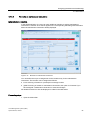
Condition monitoring
Condition monitoring is simply an indication instrument. The state of the crane components
along with the most important electrical, mechanical and hydraulic units for crane operations
are graphically displayed, as are the states of the infeed and technology function
components.
Figure 2-8
Overview, status display
The display is prepared such that components and units are easy to recognize. The state of
the elements is clearly shown by the colors used. Purely static screen objects are shown in
gray, dynamic elements are blue in normal mode, yellow in a warning state and red in a fault
state. It is crucial that the critical states can be recognized at a glance by the color alone.
The information displayed should be kept to a minimum. Precisely the information which the
crane driver or service technician needs to reliably perform his work is normally displayed. If
necessary, detailed information can be added.
Crane Management System (CMS)
24
System Manual, 03/2011
Functions of CMS
2.4 Condition monitoring
Table 2- 2
Symbol
Status display using a converter as example
Symbol
flashes
-
Description
Converter inactive / off
Converter ready to start
-
Converter active / on
-
Converter warning
-
Converter fault
An overview display shows the crane overview with the crane's main movements. The
following screen shows an example of an STS crane. The trolley movement is displayed
from the view of the crane driver. Displaying the hoist position helps the crane driver by
providing him with a view he wouldn't otherwise have.
Crane Management System (CMS)
System Manual, 03/2011
25
Functions of CMS
2.4 Condition monitoring
①
②
③
④
⑤
⑥
⑦
Movement of the trolley with limit switches, operating mode and park position display
Movement of the hoist with limit switches and operating mode
Movement of the long travel with limit switches and operating mode
Position of the boom (bottom, top, 45° or none of the three positions)
Size and load of the spreader
Positioning of the vehicles and number of the lane (Truck Positioning System)
Detailed information about the individual components (here: trolley)
Crane Management System (CMS)
26
System Manual, 03/2011
Functions of CMS
2.5 Process control
The CMS has a graphic fault display so that faults can be visually localized.
● The group fault display ① at the top edge of the screen shows the faulty component.
● In the secondary navigation bar ②, the button that is assigned to this component flashes.
● The cause of the fault ③ can be taken from the screen activated by pressing button ②.
● The cause of the fault ④ can be investigated in more detail using the associated text
message ④.
2.5
Process control
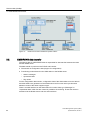
In most cases, the CMS is simply used as a tool for displaying operating states. Control of a
value on the crane controller by the CMS add-on is protected, which means that the operator
has to have the appropriate rights and has to confirm this by acknowledging a security
prompt.
In principle, CMS also offers the option of initiating operator actions by sending control
commands to the crane controller (e.g. to switch-on auxiliary systems). Auxiliary systems
can be switched on using special operator control buttons with integrated status display. In
this case, each operator control button has several states:
Crane Management System (CMS)
System Manual, 03/2011
27
Functions of CMS
2.5 Process control
Operation of the function disabled.
Function is not active.
Activation of the function is requested at the controller.
Function is active. Acknowledgment from the controller.
Another example is the option for presetting parameters and counter values.
Figure 2-9
Overview of the process control
Crane Management System (CMS)
28
System Manual, 03/2011
Functions of CMS
2.6 Fault diagnostics
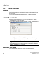
2.6
Fault diagnostics
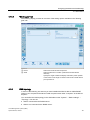
The CMS acquires the fault messages from different components of the crane. The
messages are archived, and can be displayed and evaluated using different resources:
● Message list in the user interface
● Report in the PDF and CSV format
● Message statistics (hit list)
In order to support maintenance technicians when analyzing faults, various items of
information can be called for each message.
Figure 2-10
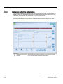
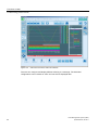
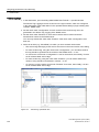
2.6.1
Overview of the fault diagnostics
Message lists
The current message list provides an overview of the crane's current queued messages.
Each message is displayed as a separate message line. Various information about a
message can be displayed in a message line. The following is displayed in the standard
application:
● Message number
● Time stamp
Crane Management System (CMS)
System Manual, 03/2011
29
Functions of CMS
2.6 Fault diagnostics
● Message text
● Group
● Plant ID (PID)
● Location ID (LID)
● Device ID (DID)
As soon as the cause of a message has been remedied, the corresponding message line
disappears from the current message list.
The message history can be tracked in the archive list. One message line is displayed for an
incoming message and one for an outgoing message. The message line is structured in the
same way as the message list, but additional items are displayed here:
● Message status (incoming: +; outgoing: -)
● Length of message
The messages displayed in both the current message list and the archive list can be filtered
using a predefined filter bar ①. In the CMS standard application, filtering according to
different crane components, message number or according to alarm class (fault, warning,
event) has been configured.
①
②
Filter bar
Message list (actual messages / archive)
Figure 2-11
Archive list of the messages
Crane Management System (CMS)
30
System Manual, 03/2011
Functions of CMS
2.6 Fault diagnostics
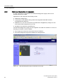
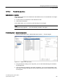
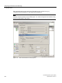
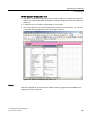
2.6.2
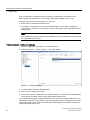
Message statistics
The message statistics evaluate the frequency and average message length for the
messages which have occurred.
The hit list ① shows an overview of the message numbers, displayed in descending order
by frequency. For every selected entry of the hit list, an overview of the messages in an
archive list can be additionally displayed by pressing button ②.
①
②
Hit list
Message statistics
Button
Opens an archive list
Crane Management System (CMS)
System Manual, 03/2011
31
Functions of CMS
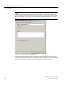
2.6 Fault diagnostics
2.6.3
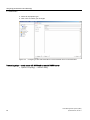
Maintenance instructions and guidelines
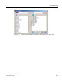
You can save maintenance instructions for every message in the CMS. These can then be
displayed when the selected message appears. Maintenance instructions can include any
information about causes and instructions on how to resolve the fault.
As well as calling up information that has been saved, you can also add inputs to a
maintenance instruction during operation, which can also be used by other users in the
future.
①
②
Maintenance instructions Shows saved maintenance instructions for the message selected
Remarks
Input of remarks about maintenance instructions
Crane Management System (CMS)
32
System Manual, 03/2011
Functions of CMS
2.6 Fault diagnostics
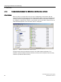
2.6.4
References to additional information
As with the maintenance instructions, you can save references for any message
● Circuit diagrams
● Symbols and networks in the crane controller's control program
● Programming Manuals
● Web pages
● Drawings
The references that are displayed depend on the programs installed on the PC. The
reference is not opened in the CMS itself, but in a program installed on the PC.
The references available must be in a local path on the CMS station or in a network path
which can be accessed from various stations.
As with the maintenance instructions, the list of references available for a message is shown
together with an archive list.
Crane Management System (CMS)
System Manual, 03/2011
33
Functions of CMS
2.6 Fault diagnostics
2.6.5
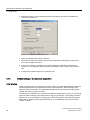
Web-based diagnostics of components
If crane components or subsystems have web-based diagnostics pages, these can be
activated directly in the CMS.
Applications for this diagnostic functionality include:
● SIMOTION IT diagnostics
● Components of the SIMATIC family (CPUs with integrated PROFINET interface,
Industrial Ethernet Switches)
● SIMATIC PCs; one of the accessories provided with the DiagMonitor package is a web
server which offers diagnostics for your PC.
● Spreaders from well-known manufacturers
The web-based diagnostics pages can be integrated in the CMS user interface. For this, the
following preconditions must be fulfilled:
● The component involved can be accessed via its IP address.
● The relevant diagnostic pages are enabled on the target device.
Figure 2-12
Web-based diagnostics page of a SIMATIC S7-300 CPU
Crane Management System (CMS)
34
System Manual, 03/2011
Functions of CMS
2.7 Operational data
2.7
Operational data
2.7.1
Recording operational data
The operational data that can be acquired with the CMS include:
● Cargo handling data; set of relevant data for a cargo handling operation
● Mean Moves Between Failure (MMBF); the so-called MMBF value reflects the average
amount of cargo handling between two faults of relevance to MMBF (cargo handling /
fault). The mean value relates to a fixed time range. A fault of relevance to MMBF is a
fault which cannot be rectified by a crane driver, but which causes a crane to stop
operating.
● Load and operating hours counter values
2.7.2
Cargo handling data
You can acquire a set of relevant operational data for each cargo handling operation
("Move") in the CMS. A cargo handling data set includes for example:
● Weight
● Transport direction
● Operating mode
● Positions
● specific data (e.g. container sizes for container cranes)
A default data set for recording cargo handling data is initialized in the CMS standard
application. This default data set can be expanded in any way.
Data is collected on the controller. The CMS supports two different recording modes:
● Direct recording of data:
As soon as the end of one cargo handling process has been detected on the controller,
the event is reported to the CMS which reads the data set and sets the time stamp.
● Data recording with backup:
The controller is initialized for backing up data sets. In this case the time stamp must be
set on the controller and transferred to the CMS with the data set.
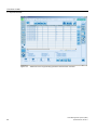
The cargo handling data is displayed in tables in the CMS standard application. You can
filter the way the data sets are displayed by different time slices.
Crane Management System (CMS)
System Manual, 03/2011
35
Functions of CMS
2.7 Operational data
Figure 2-13
Tabular list of the cargo handling operations that have been recorded
Crane Management System (CMS)
36
System Manual, 03/2011
Functions of CMS
2.7 Operational data
2.7.3
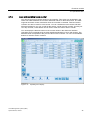
Load and operating hours counter
You can record current counter values on the controller. Time slices can be defined in the
CMS. The CMS calculates the counters' differential values for these time slices. The CMS
supports automatic counter restoration when the controller is reloaded. Total and section
counters can also be used for each counter. You can visualize the total counter and total
kilometer reading for your car, as well as the section counter and trip recorder. As with your
car's trip recorder, a reset button can be used to reset the crane's section counter.
You can display the absolute values of the counter values in the CMS user interface.
Operating hours are displayed in the CMS standard application in hours and minutes. The
absolute value corresponds to the process value on the controller. You can use the RESET
buttons to reset the section counters.
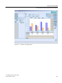
Figure 2-14
Operating hours display
Crane Management System (CMS)
System Manual, 03/2011
37
Functions of CMS
2.8 Reporting
2.8
Reporting
2.8.1
WinCC report system
The WinCC protocol system (Report Designer) can be used to prepare data recorded during
the runtime in various output formats. The reports can be printed, saved as a file and
displayed as a preview on the screen.
The reports are based on configurable templates in which data can be brought together in
precise accordance with requirements. Protocols are therefore available for current or
archived messages or the operational data displayed.
The standard application contains the following reports:
● the current message list
● the alarm log
● the cargo handling data
● the MMBF data
● the current counter values
All standard reports are based on a tabulated presentation of the default data in the CMS
standard application. Note that you have to adapt the data to your project as soon as you
have changed requirements.
Crane Management System (CMS)
38
System Manual, 03/2011
Functions of CMS
2.8 Reporting
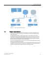
Figure 2-15
Form of display for standard reports
In the CMS standard application, the standard reports are configured in such a way that they
are always printed using the PC's standard printer. You can define the standard printer in
your PC's system control panel.
2.8.2
WinCC/Data Monitor for the CMS station
While the standard WinCC protocol system prepares the current process status and
historical data and messages in standard formats, the Data Monitor option offers further
scope for analysis and graphic preparation of data. It makes sense to use the Data Monitor
on the local CMS station if there is no central RCMS server that can be used for data
analysis.
The Data Monitor can output data in MS Excel or PDF format. The MS Excel tools for further
data editing are therefore available.
The Data Monitor "WebCenter" can be used to produce what are known as "WebCenter
pages" on the local CMS station. Various pieces of information can be provided on these
pages. The WebCenter pages can be accessed via Internet Explorer and also displayed and
edited directly in the CMS. The CMS must simply be able to access the WebCenter pages.
Crane Management System (CMS)
System Manual, 03/2011
39
Functions of CMS
2.8 Reporting
Figure 2-16
Display and analysis of operational data with the WinCC DataMonitor WebCenter
All data is displayed using standard tools such as MS Excel and MS Internet Explorer. You
can prepare reports individually put together online using event or time control and also
distribute them for analysis via the Intranet/Internet. The reports generated which can be
accessed from the Intranet/Internet can however also be called up directly in the CMS user
interface.
The user administration can be used to limit and monitor the display and editing of
information.
2.8.3
Output formats and interfaces
Depending on the version, the CMS offers different data interfaces with different output
formats:
● The CMS WinCC add-on provides operational data (cargo handling data, MMBF data,
counter values) in XML format.
● The WinCC controls for displaying archive values such as messages, move data and
MMBF data support export to CSV format.
● The Trace Viewer control for displaying trace data supports export to CSV format.
● You can use the Data Monitor option to export data archived in WinCC in MS Excel or
PDF format.
Crane Management System (CMS)
40
System Manual, 03/2011
Functions of CMS
2.9 Recording process values
2.9
Recording process values
2.9.1
Applications
The recording of process values mainly covers two applications:
● Fault analysis when the crane is at a standstill: During the fault analysis, first the trend of
various process values should be shown as a fault message. The process values in one
time range are shown in relation to the time stamp of the fault message with pre- and
posttrigger time period.
● Recording and analysis of continual process values when commissioning the crane
Another criterion for the display accuracy and the quality of the fault analysis is the resolution
of the measurement points. The higher the resolution, the more measurement points and the
higher the volume of data.
2.9.2
WinCC standard process value archiving
With WinCC Tag Logging, values with maximum 500 ms can be recorded and archived.
These values are displayed in the CMS standard application as continuous trends.
Advantage:
The advantage of WinCC standard process value archiving is that it can be quickly and
cheaply implemented.
Disadvantage:
However the disadvantage is the low resolution of the trends. since an archiving cycle of
500 ms generates an insufficient number of measurement points for the post mortem
analysis.
2.9.3
WinCC standard process value archiving with increased resolution
For the following applications, data can be prepared on the controller, collected and sent to
WinCC in one telegram:
● Process values with an interval of less than 500 ms are recorded
● Values are acquired with a time stamp from the controller
● Several values can be acquired in time synchronism
The data are entered into a WinCC Tag Logging archive with the time stamp allocated by the
controller.
For detailed information, for instance on the telegram structure, refer to the WinCC
documentation (WinCC communication manual → SIMATIC S7 PROTOCOL SUITE channel
→ Special functions).
For SIMATIC S7, there are blocks that can be parameterized for sending a telegram. In the
S7-400 automation system, there is the integrated function block SFB 37 "AR_SEND" .
Crane Management System (CMS)
System Manual, 03/2011
41
Functions of CMS
2.9 Recording process values
Advantage:
The advantage of this method is that archiving cycles of less than 500 ms are possible in
WinCC. High levels of configuration effort are not needed on the HMI side.
Disadvantage:
The high level of configuration effort impacts negatively on the controller side. In particular
there is a high level of communication between the automation system and WinCC. When
several process values are being transferred, the cycle time and transfer rate of the
communications interface must be noted.
2.9.4
CMS Fast-Trace – SIPLUS CMS
SIPLUS CMS is a high-performance condition monitoring product for recording high-speed
trace data.
The hardware for the SIPLUS CMS comprises what are known as URNs (User Nodes) and
so-called IONs (Input Output Nodes). The URNs are components for administering, saving
and visualizing the data recorded. The X-Tools software included in the scope of delivery is
needed for this. The IONs are used to record data and forward it to X-Tools.
The following IONs can be used:
● Software IONs
SIPLUS CMS records the data directly from the SIMATIC S7 and SIMOTION controllers
using appropriate software IONs (Input-Output Nodes).
● Hardware IONs
The SIPLUS CMS product range includes a series of hardware IONs which can be used
to directly record measured values. The huge benefit of this option is that measured
variables can be recorded precisely where they occur. This avoids incorrect
interpretations which may result from the time taken to transmit via a controller.
● PROFIBUS ION
The PROFIBUS ION, also known as "Spy", is particularly versatile. This module can be
used to record any values which pass via the PROFIBUS. The spy is a totally passive
node and affects neither the bus nor the cycle time of controllers.
Crane Management System (CMS)
42
System Manual, 03/2011
Functions of CMS
2.9 Recording process values
Figure 2-17
SIPLUS CMS configuration
The "X-Tools" software tool is used for configuration and evaluation. Data can be analyzed in
real-time (online data) as well as archived for subsequent analysis (offline data). Saving data
is configured using what are known as "Storage Profiles".
SIMOCRANE CMS provides a "Trace-Viewer" for conveniently displaying saved offline data,
embedded in the CMS user interface. Starting from an error message, you can easily select
and display the saved trace data.
Crane Management System (CMS)
System Manual, 03/2011
43
Functions of CMS
2.9 Recording process values
Figure 2-18
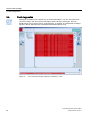
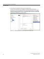
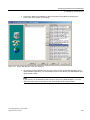
CMS Fast Trace in the CMS user interface
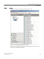
The user can configure and display different referring to a message. The individual
configurations can be saved as "sets" and can also be displayed later.
Crane Management System (CMS)
44
System Manual, 03/2011
Functions of CMS
2.9 Recording process values
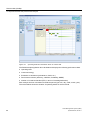
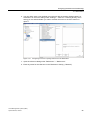
Figure 2-19
Configuring a set of available trace data in the WinCC control of the Trace Viewer
Crane Management System (CMS)
System Manual, 03/2011
45
Functions of CMS
2.9 Recording process values
Crane Management System (CMS)
46
System Manual, 03/2011
Remote CMS (RCMS)
3
Larger plants usually have a control room with one or more operator stations, used to
monitor the entire plant. The data from all subordinate local CMS stations is collected,
displayed and evaluated here.
Remote access to CMS stations is also possible. In the crane environment, this is therefore
known as "Remote CMS" (RCMS). In fault scenarios, diagnostic information can therefore be
called up in advance. In the best case scenario, a fault can be resolved in this way.
This chapter provides an overview of the system design and main functions which the
remote CMS (RCMS) provides for monitoring the entire plant and remote access to CMS
stations.
In addition to the possibility of pure remote access to the CMS stations of the cranes via
WinCC Web Navigator, RCMS can be implemented as data server with its own operator
station and additional remote access to the cranes. The focus here is on the complete
system, not on a single crane. Cranes of the same type can be compared in order to locate
weak points. Determining what are known as KPIs (Key Performance Indicators) and
overviews of operation modes, downtimes etc. play a key role at this point.
● Overall plant overview (cartographic)
● Status display for several cranes
● Status display for the stacking area
● Data analysis across all connected crane systems
● Availability overview
● Higher-level performance analyses
● Long-term archiving
Crane Management System (CMS)
System Manual, 03/2011
47
Remote CMS (RCMS)
Figure 3-1
Remote access to several cranes
Figure 3-2
RCMS server (central or remote CMS)
Crane Management System (CMS)
48
System Manual, 03/2011
Remote CMS (RCMS)
3.1 RCMS topology
3.1
RCMS topology
You always require the WinCC Web Navigator Server on the CMS stations in order to
remotely access the cranes. This allows you to see the CMS user interface on the remote
PC.
Figure 3-3
RCMS topology remote access
The RCMS server archives operational data and messages from all connected cranes
(CMS), provides different evaluation and display options, and offers remote access to the
CMS stations of the individual cranes.
Depending on the particular requirement, the RCMS can be configured differently:
● RCMS server without additional operator stations (RCMS server - single)
● RCMS server with one or several central operator stations (RCMS server - client)
Crane Management System (CMS)
System Manual, 03/2011
49
Remote CMS (RCMS)
3.2 CMS-RCMS data transfer
Figure 3-4
3.2
RCMS server without additional operator stations
CMS-RCMS data transfer
The WinCC add-on SIMOCRANE CMS is responsible for data transfer between the CMS
and the RCMS server.
The data transfer is performed via TCP/IP and includes:
● The transfer of configuration data (support for configuration)
● Transferring runtime data from the CMS station to the RCMS server:
– WinCC messages
– Operational data
– Tag values
For the configuration data transfer, configuration data of the CMS stations from the WinCC
and CMS editors are generated on the RCMS server and in some cases synchronized
between cranes of the same equipment type.
There is an XML interface on the CMS station for runtime data, type "Messages" or
"Operational data". XML files are created in parallel to the archiving. These files are then
transferred to the RCMS server and also archived there.
Crane Management System (CMS)
50
System Manual, 03/2011
Remote CMS (RCMS)
3.3 Design of user interface
Figure 3-5
3.3
CMS – RCMS data synchronization
Design of user interface
One or more RCMS operator stations are integrated into a topology, depending on the
circumstances involved. However, from a functionality perspective, the RCMS operator
stations are identical.
An RCMS operator station is a central operator station used to display archived and
evaluated data. It also supports visualization of the entire plant and remote access to the
CMS stations. The RCMS standard application supplied provides an example of how the
terminal overview, message lists of all connected cranes, and the analysis of operational
data and performance across all cranes can be displayed.
You can use the Web Navigator remote access function to view the CMS station's screens
directly from the RCMS operator station.
The diagram below shows an example of how an RCMS operator station with two screens is
structured. The terminal overview can therefore be displayed on the first screen and at the
same time the CMS screens via Web Navigator on the second screen.
Crane Management System (CMS)
System Manual, 03/2011
51
Remote CMS (RCMS)
3.3 Design of user interface
Figure 3-6
RCMS operator station with two screens
The screen frame of the RCMS operator station is similar to the CMS station.
The RCMS application has three menus:
● Status display with the terminal overview focus
● Fault diagnostics
● Analysis
Crane Management System (CMS)
52
System Manual, 03/2011
Remote CMS (RCMS)
3.4 Terminal overview
3.4
Terminal overview
3.4.1
Cartographic display
The RCMS application contains a cartographic overview and also displays the terminal as a
tree structure.
Once in the cartographic overview, you can move around the map of the terminal. To do this,
you are provided with simple navigation tools to allow you to move up/down the screen and
move to the left/right. There is also a zoom function and a smaller overall view with section
positioning.
Figure 3-7
Total plant view (cartographic)
The cartographic representation enables you to display the individual berths, the stacking
areas, routes as well as relevant terminal buildings. If the cranes, trucks or straddle carriers
are equipped with a GPS receiver, their position within the terminals can be visualized using
a symbol in the screen. In addition, the symbol color indicates the operating state. In the
RCMS application, this display is realized for some sample cranes. In the following, an STS
crane:
Crane Management System (CMS)
System Manual, 03/2011
53
Remote CMS (RCMS)
3.4 Terminal overview
OK / in operation
Idle
Warning present
Fault present
No connection to the crane
WinCC / CMS Runtime stopped
No connection to the controller
Undefined status
If you position your mouse on a component in the overview of the RCMS application, then
the name of the component is displayed as tooltip text. Click the component to call up the
available detailed information (description, position, operating mode, load, etc.) in the
detailed view on the right-hand side. The magnifying glass allows you to call up the screens
of the crane's CMS station via remote access; see Remote access (Page 60).
3.4.2
Tree view and statistics
In addition to the cartographic display, the RCMS application also features a tree structure
showing all of the cranes that are available. The tree display is a WinCC control from the
CMS WinCC add-on (CMS Node Tree Control). The tree topology is defined in the CMS
editor.
Within the tree, cranes are assigned to a terminal and an equipment type (e.g. STSCrane).
You can also follow the operating states of the various cranes here as they change color
(see above). The tree view allows you to select individual cranes and call up the following
information:
● Total number of all cranes for a terminal or cranes for the selected equipment type (e.g.
"STSCrane").
● Number of offline components for the selected equipment type
● Number of standby components for the selected equipment type
● Number of components in operation for the selected equipment type
● Number of components with a warning pending for the selected equipment type
● Number of faulty components for the selected equipment type
Crane Management System (CMS)
54
System Manual, 03/2011
Remote CMS (RCMS)
3.4 Terminal overview
The start page shows the tree view alongside current statistics for the terminal. The statistics
are based on information from the tree view.
Figure 3-8
Tree view for the terminal
Crane Management System (CMS)
System Manual, 03/2011
55
Remote CMS (RCMS)
3.5 Fault diagnostics
3.5
Fault diagnostics
Messages are displayed in a similar way as for the CMS station. You can call up the list of
current messages, the list of archive messages, and the hit list of messages. The tree
display allows you to select a crane, equipment type, or terminal. The associated messages
appear in the list. Message lists are filtered with standard WinCC tools.
Figure 3-9
List of archived messages, filtered by "STSCrane1" crane
Crane Management System (CMS)
56
System Manual, 03/2011
Remote CMS (RCMS)
3.6 Operational data and performance analysis
Figure 3-10
3.6
Hit list of messages for all cranes
Operational data and performance analysis
As well as displaying cargo handling data and MMBF data in a table, the RCMS server
handles additional operational data and performance evaluations from the WinCC downtime
monitor.
CMS-RCMS data synchronization makes the recorded operational data of all connected
CMS stations available to the RCMS server in WinCC archives.
Based on a defined time model, the crane's status word, and the counters, the WinCC
downtime monitor performs calculations to assess the counters and analyze the operating
states. It is able to establish key performance indicators (KPI) such as a crane's availability,
utilization, performance, and MMBF value. Each crane is set up as equipment in the
Downtime Monitor. Analysis results are determined for each crane.
Based on the time model, the RCMS sample application represents the operating states and
downtimes both graphically (Gantt chart) and in the form of a table.
Crane Management System (CMS)
System Manual, 03/2011
57
Remote CMS (RCMS)
3.6 Operational data and performance analysis
Figure 3-11
Operating states and downtimes shown in a Gantt chart
The RCMS sample application also calculates and displays the following performance data:
● Operating state
● Consumed energy
● Evaluation of downtimes (maintenance, faults, etc.)
● Performance indictors (efficiency, utilization, availability, MMBF)
● Number of containers handled (TEU, in terms of size/weight/direction)
Each analysis involves calculations for different periods (per hour, day, week, month, year).
The screen below shows the duration of operating states for the last month.
Crane Management System (CMS)
58
System Manual, 03/2011
Remote CMS (RCMS)
3.6 Operational data and performance analysis
Figure 3-12
Duration of operating states
Crane Management System (CMS)
System Manual, 03/2011
59
Remote CMS (RCMS)
3.7 Remote access
3.7
Remote access
Using WinCC Web Navigator, either the RCMS operator stations or any other stations can
access the CMS station. The user sees the screens of the CMS station, but is also able to
move freely within the screens.
The following diagram shows the an example of the web client calling up the CMS screens
for a crane from the RCMS operator station.
Figure 3-13
WinCC Web Navigator in the RCMS operator station
Crane Management System (CMS)
60
System Manual, 03/2011
Assigning parameters and addressing
4
This chapter describes the fundamental settings you need to undertake in the CMS standard
application in order to integrate them into your project environment (crane type settings,
network topology, basic settings in WinCC).
The RCMS example application also supplied is suitable as an RCMS server for the local
CMS station. Here too, this chapter describes the fundamental settings for integrating the
standard application into your project environment and starting CMS-RCMS data
synchronization.
This chapter is therefore mainly aimed at people who have to adapt the CMS standard
application to specific requirements.
4.1
CMS station
4.1.1
Starting the CMS Runtime automatically
Ensure that the "CMSRuntime.exe" of the SIMOCRANE CMS WinCC add-on is entered in
the Windows start-up list.
You can check whether the program has been started using the symbols in the Windows
taskbar (see the operating instructions for SIMOCRANE CMS).
4.1.2
Settings in WinCC
Initial situation
In order to start the standard application on your PC, you first have to undertake some basic
settings in WinCC so that the standard application's defaults can be adapted to your project
environment.
Processing steps
1. Enter the name of your PC in WinCC Explorer under "Computer properties", "General"
tab.
Crane Management System (CMS)
System Manual, 03/2011
61
Assigning parameters and addressing
4.1 CMS station
Note
Please note that the computer name must not be "CMS". You should also observe the
WinCC guidelines for the assignment of a computer name. If the computer name should
be the same as the crane name, then it may contain letters and numbers only. The first
character must be a letter.
Figure 4-1
PC name setting in WinCC Explorer
2. Check the language settings for WinCC Runtime under the "Parameters" tab. Enter the
runtime language required. "English" is the default runtime language in the CMS standard
application. "German" is offered as the second language in delivery condition.
Crane Management System (CMS)
62
System Manual, 03/2011
Assigning parameters and addressing
4.1 CMS station
Figure 4-2
Runtime language setting in WinCC
Result
After restarting WinCC, you can launch the WinCC Runtime.
Note
Please note that after changing the computer name you will have to restart WinCC before
you can make any further settings in the CMS editor.
Crane Management System (CMS)
System Manual, 03/2011
63
Assigning parameters and addressing
4.1 CMS station
4.1.3
Communication between the CMS station and the crane controller
Initial situation
Based on WinCC, the CMS offers various ways of establishing communication with the
control level. The channels support various communication drivers. All tags are administered
centrally in WinCC in tag management. You will find the interface to the crane controller in
the "SIMATIC S7 PROTOCOL SUITE" communication driver in the "MPI" channel unit in the
CMS standard application. The connection name is "CMS_MPI".
Figure 4-3
SIMATIC S7 PROTOCOL SUITE channel
The figure below shows the interface structure of the CMS standard application. The
interface is split into different modules. Modules are firstly crane components and secondly
modules of operational data recording.
Crane Management System (CMS)
64
System Manual, 03/2011
Assigning parameters and addressing
4.1 CMS station
Figure 4-4
Interface overview
In the SIMATIC S7, a separate data block is defined for every module which forms the
interface to the CMS. The data can be addressed in WinCC tag management via the data
block and an offset in the corresponding data block. The offset, type and size of the data are
described in the interface.
With a few exceptions, binary diagnostic information is read as one byte and not as a word
or double word. This should prevent misunderstandings caused by different processor
architectures. High and low bytes are swapped within one word for different processor
architectures. The interface description is always based on the byte order in WinCC.
Processing steps
You should note the following components when assigning parameters for communication:
1. Establish the physical connection between the automation system, the crane controller
and the CMS station's computer.
2. Define the communication driver for your project (e.g. "SIMATIC S7 PROTOCOL
SUITE").
3. Define the channel unit (e.g. TCP/IP).
4. Create a logical connection in the channel unit (e.g. CMS_TCPIP).
Crane Management System (CMS)
System Manual, 03/2011
65
Assigning parameters and addressing
4.1 CMS station
5. Address the WinCC communications partner in the logical connection and define the
connection parameters.
Figure 4-5
TCP/IP connection parameters
6. Open tag management in WinCC Explorer.
7. Move (do not copy!) the interface tags from the preassigned "CMS_MPI" connection to
your newly created connection.
8. If you have created a connection in a channel outside the SIMATIC S7 PROTOCOL
SUITE, you must adapt the addressing the requirements of the corresponding channel
unit.
9. Configure the interface tags on the controller side.
4.1.4
Default settings in the standard application
Initial situation
Some parameters that are required in the status display of the standard application (limits for
traveling distances) can be parameterized in the runtime interface, without changing the
WinCC screens in the editor. This parameter assignment can be performed during system
runtime and does not require a restart.
The settings you undertake in the runtime are written to internal WinCC tags. You can find all
tags that contain settings in the internal WinCC tag group "Settings". The property "Runtime
Persistence" is set for all tags of this tag group. This means that the value that this tag had
before WinCC Runtime was stopped the last time, is re-established the next time that the
runtime is started.
Crane Management System (CMS)
66
System Manual, 03/2011
Assigning parameters and addressing
4.1 CMS station
Figure 4-6
Runtime persistency
Processing steps
1. Start the WinCC Runtime.
2. Log onto the start page of the CMS user interface as an administrator.
3. Open the "Settings" menu and define your parameters in the individual tabs of the menu.
Crane Management System (CMS)
System Manual, 03/2011
67
Assigning parameters and addressing
4.1 CMS station
4.1.4.1
"General" tab
The following display provides an overview of the setting options available in the "General"
tab.
①
Operator enable
②
Select whether the operating functions in the CMS should be
restricted to a certain PC (e.g. Web client in the crane cabin).
Then, enter the name of the PC.
Technology functions
③
Select the technology functions present. Enter the computer
name (if present) of the Web Navigator client PC in the crane
cabin if you want to restrict operation of the technology functions
to this PC.
Supply units
④
Change the number of supply units displayed in the "Main Supply
Units" tab of the CMS standard application.
SIMATIC S7 web server
⑤
Select whether in your project the web server on the SIMATIC S7
CPU is activated. Then enter the IP address of your S7.
SIMOTION web server
⑥
Select whether in your project the web server on SIMOTION is
activated. Then enter the IP address of your SIMOTION.
SIPLUS Trace Viewer
Select whether the SIPLUS Trace Viewer is to be used in your
project. Then enter the IP address and the port number of the
Trace Viewer server.
Crane Management System (CMS)
68
System Manual, 03/2011
Assigning parameters and addressing
4.1 CMS station
4.1.4.2
"Hoist" tab
The following display provides an overview of the setting options available in the "Hoist" tab.
①
②
③
④
Drives
Select from the drives that are present.
Spreader
Select this option if a tandem spreader is being used.
Positions
"maximum position": Specify the maximum traversing
position of the hoist.
"minimum position": Specify the minimum traversing
position of the hoist.
Remaining traversing distance
(bottom edge of spreader → settling
position)
"Prelimit Ground" Specify the position as of which the
remaining traversing distance will be displayed to the
crane driver.
"Limit Ground": Specify the position as of which the crane
driver will be warned that there is not much residual
traversing distance left.
Crane Management System (CMS)
System Manual, 03/2011
69
Assigning parameters and addressing
4.1 CMS station
4.1.4.3
"Trolley" tab
The following display provides an overview of the setting options available in the "Trolley"
tab.
① Drives
② Positions
Select from the drives that are present.
"maximum position": Specify the maximum traversing position of the
trolley.
"minimum position": Specify the minimum traversing position of the
trolley.
Crane Management System (CMS)
70
System Manual, 03/2011
Assigning parameters and addressing
4.1 CMS station
4.1.4.4
"Boom-hoist" tab
The following display provides an overview of the setting options available in the "Boomhoist" tab.
①
Drives
Select from the drives that are present.
Crane Management System (CMS)
System Manual, 03/2011
71
Assigning parameters and addressing
4.1 CMS station
4.1.4.5
"Gantry" tab
The following display provides an overview of the setting options available in the "Gantry"
tab.
①
②
Drives
Select from the drives that are present.
Positions
"maximum position": Specify the maximum traversing position of
the gantry.
"minimum position": Specify the minimum traversing position of the
gantry.
Crane Management System (CMS)
72
System Manual, 03/2011
Assigning parameters and addressing
4.1 CMS station
4.1.4.6
"Slewing gear" tab
The following display provides an overview of the setting options available in the "Slewing
gear" tab.
①
②
Drives
Select from the drives that are present.
Scale
Select the direction of rotation (clockwise/counterclockwise
direction).
Specify the angle at which the display instrument points upwards
in the screen for the angle of rotation under "Index needle should
point upwards at".
4.1.5
CMS topology
In terms of the following, we assume you have installed the WinCC add-on SIMOCRANE
CMS on your computer and entered a valid computer name under "Computer" in the WinCC
Explorer.
You can define the CMS topology in the CMS editor under "System" → "Basic settings" →
"Topology". You can set:
● CMS is connected to the RCMS server.
● CMS is not connected to the RCMS server.
Crane Management System (CMS)
System Manual, 03/2011
73
Assigning parameters and addressing
4.1 CMS station
The "One terminal" or "Multiple terminals" setting is needed later on the RCMS server.
After installing the CMS add-ons, the topology "CMS without RCMS server" is set.
Depending on the project requirements, you can now
● define either a CMS without RCMS server
● or change the topology to form a CMS with RCMS server; in this case, configure this
CMS so that in your project environment you can subsequently synchronize data with the
RCMS server.
Note
Some dialogs of the CMS editor are only available to you if your Windows user belongs to
the CMS administrator group.
Processing steps - setting the topology
1. Open the CMS editor using the icon in WinCC Explorer.
2. Open the "System" → "Basic settings" → "Topology" dialog.
Figure 4-7
Changing topology
3. In the list, select "CMS with RCMS server".
4. Click "OK" to confirm your change.
5. Close and re-open the CMS editor to accept the setting. The CMS with connected RCMS
server has more setting options than a CMS without RCMS server.
If you selected the topology "CMS with RCMS server", then each change of the data in the
CMS editor is marked in color (yellow). This marking indicates that a change has been made
at the CMS station, which is still not available at the RCMS (also see Chapter Transferring
configuration data (Page 137)).
Crane Management System (CMS)
74
System Manual, 03/2011
Assigning parameters and addressing
4.1 CMS station
Processing steps – create equipment type
Every crane in the CMS must be assigned to a specific equipment type.
1. Open the "Topology" → "Equipment" dialog.
Crane Management System (CMS)
System Manual, 03/2011
75
Assigning parameters and addressing
4.1 CMS station
Figure 4-8
Defining the equipment type in the CMS editor (topology "CMS without RCMS
server")
2. You can define the equipment type for your crane (e.g. "STSCrane") here.
Note
Note that the name of the equipment type may only contain letters and numbers. The first
character of the name must be a letter.
3. If you selected the topology "CMS with RCMS server", then your equipment type
presently being processed and the associated entry is shown in the editor tree as
"changed".
Crane Management System (CMS)
76
System Manual, 03/2011
Assigning parameters and addressing
4.1 CMS station
Figure 4-9
Defining the equipment type in the CMS editor (topology "CMS with RCMS server")
Processing steps – create crane with CMS without RCMS server
1. Open the "Topology" → "Cranes" dialog.
2. You can enter the name of your crane in the "Name" field (e.g. "STSCrane1").
Note
Note that the crane name may only contain letters and numbers. The first character of the
crane name must be a letter.
3. Enter the computer name for the CMS station in the "Computer name" field.
Note
Please note that the computer name cannot be precisely called "CMS". You should also
observe the WinCC guidelines for the assignment of computer names. If the computer
name should be the same as the crane name, then it may contain letters and numbers
only. The first character of the computer name must be a letter.
Crane Management System (CMS)
System Manual, 03/2011
77
Assigning parameters and addressing
4.1 CMS station
4. Select an equipment type.
5. Click "OK" to confirm your changes.
Figure 4-10
Configuring a crane with CMS without connected RCMS server in the CMS editor
Processing steps – create crane with CMS and connected RCMS server
1. Open the "Topology" → "Cranes" dialog.
Crane Management System (CMS)
78
System Manual, 03/2011
Assigning parameters and addressing
4.1 CMS station
Figure 4-11
Configuring a crane with CMS and connected RCMS server in the CMS editor
2. Enter the name of the crane in the "Name" field (e.g. "STSCrane1").
Note
Note that the crane name may only contain letters and numbers. The first character of the
crane name must be a letter.
3. Enter the computer name for the CMS station in the "Computer name" field.
Note
Please note that the computer name cannot be precisely called "CMS". You should also
observe the WinCC guidelines for the assignment of computer names. If the computer
name should be the same as the crane name, then it may contain letters and numbers
only. The first character of the computer name must be a letter.
4. Select an equipment type (e.g. "STSCrane") under "Equipment type".
5. Specify the IP address of the RCMS server in the "IP-Address RCMS" field.
6. Enter the number of the port that is to be used for communication with the RCMS server
in the "Port number" field. Ensure that the port number is the same on the CMS and
RCMS sides.
7. The "IP Address CMS" field remains empty if your PC only has one network card. If your
PC has several network cards, then the IP address, via which communication is
established with the RCMS server, must be located in this field.
Crane Management System (CMS)
System Manual, 03/2011
79
Assigning parameters and addressing
4.1 CMS station
8. In the field "Crane status tag", select the WinCC process tag in which the controller sends
the status of the crane. The status word is especially used on the RCMS server (see
Chapter RCMS topology (Page 149)). Transfer to the RCMS server is realized
automatically. Here, the tag receives the crane name as a prefix.
9. Specify the RCMS update cycles for messages and operational data.
10.Select "Crane is synchronized with RCMS". If this option is not selected, then neither
configuration data nor runtime data will be transferred.
11.Confirm with "OK".
If you selected the topology "CMS with RCMS server", then the crane that you are
presently processing and the associated entry are shown in the editor tree as changed.
12.Restart CMS Runtime to activate the changes to the communication parameters.
4.1.6
CMS system tags
There is a range of system tags which is automatically created and supplied in a "CMS" tag
group on the CMS station. Their content is entered in runtime, e.g. from the information of
the CMS editor (Topology → Cranes).
Table 4- 1
CMS system tags
Tag name
Data type
Bit Description
@CMSCraneName
Text tag 8-bit
character set
-
Name of the crane
@CMSEquipment
Text tag 8-bit
character set
-
Equipment type to which the crane belongs
@CMSIPAddress
Text tag 8-bit
character set
-
IP address of the CMS station
@CMSConnectionState
Unsigned 16-bit
value
Connection status to the RCMS server
0
(CMS station / RCMS server)
When starting the CMS Runtime, no major errors
occurred. All local functions are active. There is no
connection to the RCMS server.
1
(CMS station / RCMS server)
When starting the CMS Runtime, no major errors
occurred. All local functions are active. The
connection to the RCMS server / to all CMS
stations is active.
2
(RCMS server)
When starting the CMS Runtime, no major errors
occurred. All local functions are active. The
connection to at least one CMS station is not
active.
Crane Management System (CMS)
80
System Manual, 03/2011
Assigning parameters and addressing
4.1 CMS station
Tag name
Data type
Bit Description
7
4.1.7
(CMS station / RCMS server)
CMS Runtime cannot run. When starting CMS
Runtime, a fault has occurred that prevents CMS
Runtime from being executed (e.g. WinCC
Runtime has not been started, a crane has not
been defined in the CMS editor, a wrong computer
name has been entered into the CMS editor, ...).
You can find more information on this fault in the
CMS error file in the folder …\CMS of the WinCC
project directory.
Alarm/event system for the CMS station
The CMS alarm/event system is based on WinCC Alarm Logging. Additional crane-specific
requirements of the alarm/event system are covered by the CMS add-on for WinCC. While
the WinCC messages are displayed in a WinCC Alarm Control, the CMS add-on provides a
separate control of additional message information. It has already been integrated into the
CMS standard application (MessagesInfo.pdl ).
You can find a detailed description of this integration in Chapter Additional message
information in the CMSFaults control (Page 187).
4.1.7.1
Message procedures
The WinCC Alarm Logging basically supports two message procedures:
● Bit message procedure (message tag)
● Chronological reporting (message telegram)
The CMS standard application uses the bit message procedure. Here the controller signals
the occurrence of an event by means of a message tag. The time stamp of the message is
issued by WinCC Alarm Logging.
With chronological reporting, the time stamp of an alarm event is issued by the controller and
sent to WinCC as a message telegram. This message procedure assumes the appropriate
configuration on the controller side.
4.1.7.2
Message blocks
Message blocks are configured in the WinCC Alarm Logging. They contain the information
which is displayed in a message.
The table below shows the message blocks that are defined in the CMS standard
application. You can adjust the message blocks to suit your project requirements. However,
the process value blocks 1 and 2 (crane name, equipment type) must always be used for
message transmission to the RCMS and may not be used for project-specific purposes.
Message block 10 is prepared for displaying the contents of both the process value blocks.
Crane Management System (CMS)
System Manual, 03/2011
81
Assigning parameters and addressing
4.1 CMS station
Table 4- 2
Message blocks
Name
Category
Number
Size
Description
Date
System block
1
dd:mm:yyyy
Date of time stamp
Time
System block
2
hh:mm:ss
Time of time stamp
Duration
System block
3
dd hh:mm:ss
Period between "incoming"
status and "outgoing" status
Status
System block
5
1 char
Message status (incoming,
outgoing)
Number
User text block
1
4 char
Fault number
PID
User text block
2
5 char
Plant identification (=xxx)
LID
User text block
3
5 char
Location identification (+xxx)
DID
User text block
4
5 char
Device identification (-xxx)
Message text
User text block
5
90 char
Information about the message
Source
User text block
6
12 char
S7 block / network
Reference
User text block
7
10 char
Reference in circuit diagram
Group
User text block
8
4 char
Message group
Equipment
type::
crane name
User text block
10
32 char
Mandatory attribute for
CMS/RCMS data
synchronization.
Content is mandatory:
@2%s@::@1%s@
Crane name
Process value block
1
32 char
Reserved for CMS
Equipment
type
Process value block
2
32 char
Reserved for CMS
Process
value
Process value block
3
32 char
Process value
Crane Management System (CMS)
82
System Manual, 03/2011
Assigning parameters and addressing
4.1 CMS station
4.1.7.3
Message classes and message types
Message classes and message types are configured in the WinCC Alarm Logging.
The table below shows the message classes and message types which are defined in the
CMS standard application. The message class 16 (CMS) and the subordinate message
types are mandatory for use in CMS system messages and may not be changed. The
message class is created automatically. You can modify all other message classes and
message types.
Table 4- 3
Message classes and message types
Class
Class
number
Type
Type
number
Status
Fault
1
Fault in
general
1
incoming
(+)
Color
outgoing
(-)
Warning
4
Warning in
general
49
incoming
(+)
outgoing
(-)
Event
7
Info Operator
97
incoming
(+)
outgoing
(-)
MMBF
14
External
209
incoming
(+)
outgoing
(-)
Internal
210
incoming
(+)
outgoing
(-)
CMS
16
CMS fault
241
incoming
(+)
CMS warning
242
incoming
(+)
CMS info
243
incoming
(+)
Crane Management System (CMS)
System Manual, 03/2011
83
Assigning parameters and addressing
4.1 CMS station
4.1.7.4
Group messages
In the CMS, each WinCC single message is assigned to a group message. The group
messages are configured in the WinCC Alarm Logging and can be structured hierarchically,
so that a subordinate group message also initiates the higher-level group message. The
diagram below shows the group hierarchy of the CMS standard application:
Figure 4-12
Principle of the group message in the CMS
All of the individual messages of class "Faults of gantry 1" are assigned to an alarm group"
"GA1_Fault". If such an individual message occurs (e.g. "Gantry1 fault brake"), then the
directly assigned group message ("GA1_Fault") and also the higher-level group message
("Gantry_Fault") are output.
A status tag can be defined for each configured group message defined, in which a status bit
is set when the group message is initiated.
This status tag can be evaluated in the user interface:
● Configuring a group fault display in the group fault display (e.g. group messages level 2)
● Initiating group messages (e.g. group messages level 1)
A group fault display visualizes the message statuses in a suitable form for the message
classes of the standard application:
● Inactive (status tag = 0)
● Event (status bit 1 set)
● Warning (status bit 2 set)
● Fault (status bit 3 set)
Crane Management System (CMS)
84
System Manual, 03/2011
Assigning parameters and addressing
4.1 CMS station
The status of a group fault display is dynamized using the status tag of the group messages:
Figure 4-13
Group fault display in the CMS
Fault messages from crane gantry 1 initiate the "Gantry_Fault" group message; see diagram
"Principle of the group message in the CMS". When the group message is initiated, bit 3 in
the assigned status tags is set.
For individual messages of the class "Warning", there is an analogous hierarchy. The group
message, "Gantry_Warning" sets bit 2 in the status tags. For operator messages, there is an
additional "Event" state. Bit 1 is set in the assigned status tags. The status displays are
configured so that the fault bit has the highest priority.
The following table shows the complete group hierarchy for the message class "Fault". The
group hierarchy for the class "Warning" is structured in the same way. For events there is
only one group message.
Table 4- 4
Symbol
Group messages for visualizing the group faults
Display group
Alarm group
Description
General_Fault
GE_Fault
General crane
Supply_Fault
LVD_Fault
Low voltage distribution
SU1_Fault
Supply unit 1
SU2_Fault
Supply unit 2
SU3_Fault
Supply unit 3
SU4_Fault
Supply unit 4
CRH_Fault
Cable reel high voltage
Crane Management System (CMS)
System Manual, 03/2011
85
Assigning parameters and addressing
4.1 CMS station
Symbol
Display group
Alarm group
Description
Hoist_Fault
HO_Fault
Hoisting gear or holding and closing gear
HO1_Fault
HO2_Fault
HO3_Fault
HO4_Fault
Trolley_Fault
TR_Fault
Trolley or luffing gear
TR1_Fault
TR2_Fault
TR3_Fault
TR4_Fault
Boomhoist_Fault
BH_Fault
Boom-hoist
BH1_Fault
BH2_Fault
Gantry_Fault
GA_Fault
Gantry
GA1_Fault
GA2_Fault
GA3_Fault
GA4_Fault
Slewing_Fault
SL_Fault
Slewing gear
SL1_Fault
SL2_Fault
Spreader_Fault
Auxiliary_Fault
TechFunction_Fault
OM
SPR_Fault
Spreader
CRS_Fault
Cable reel spreader
AUX_Fault
Other auxiliary gear
TLS_Fault
Trim list skew
RT_Fault
Rope tensioning
LHV_Fault
Lighting, heating, ventilation
AUT_Fault
Automatic
TPS_Fault
"Truck positioning"
"Operator messages"
Crane Management System (CMS)
86
System Manual, 03/2011
Assigning parameters and addressing
4.1 CMS station
4.1.7.5
Archive configuration
The archive configuration for messages is defined in the WinCC Alarm Logging. Adapt the
size and archiving period of the archive and individual segment to the project requirements
under "Archive configuration".
Figure 4-14
Archive configuration of the message archive in the WinCC Alarm Logging editor
You can set how many messages are to be re-established after a power failure under
"Reload after power failure". When the system is restarting, pending messages are checked
to see if they were received before the power failure.
Figure 4-15
Reloading messages in the case of a power failure
Crane Management System (CMS)
System Manual, 03/2011
87
Assigning parameters and addressing
4.1 CMS station
4.1.7.6
Message import in the WinCC Alarm Logging
Initial situation / objective
WinCC Alarm Logging features an import function for individual messages so you don't have
to create all the messages manually. The import file must be available in text format (*.txt).
Refer to the WinCC documentation for the structure of the import file and meaning of the
parameters.
Processing steps
1. Ensure that all message classes, message types, message blocks and message groups
used in the import file are created in the WinCC Alarm Logging.
2. Ensure that all tags used (message and process value tags) are present in the WinCC
tag management.
3. Use the "Import messages" dialog to import the messages from the WinCC Alarm
Logging toolbar "Messages" → "Import individual messages…".
4. Once the import process is complete, a message appears and you can read the import
status off this. You can check here whether the import is free from faults.
4.1.7.7
Maintenance instructions in the CMS configuration editor
Initial situation / objective
You can assign a maintenance instruction to each message that is available in WinCC Alarm
Logging. Only one maintenance instruction can be assigned to each WinCC message. But
several messages can be assigned to each maintenance instruction.
Below is a description of how to manually configure a maintenance instruction. However, you
can also use an import function (xml format). It is best to start by manually configuring and
exporting an instruction. Then you can use this template to extend the import file.
The CMS operating instructions contain a detailed description of the import function.
Processing steps
Here is an example of how to configure maintenance instructions:
1. Open the CMS editor under "Messages" → "Maintenance instructions"
2. Use "New" to create a new maintenance instruction.
3. Under "Description", enter a name for the maintenance instruction (e.g. Category 0 Stop).
The "Description" field is mandatory.
Crane Management System (CMS)
88
System Manual, 03/2011
Assigning parameters and addressing
4.1 CMS station
4. In the "Possible cause" and "Possible remedy" fields enter information about a fault's
cause and remedy.
Figure 4-16
Configuring maintenance instructions in the CMS editor
5. Open the dialog for assigning maintenance instructions to a message under "Messages"
→ "Assign maintenance instructions".
You will find a list of all existing message numbers on the left.
Crane Management System (CMS)
System Manual, 03/2011
89
Assigning parameters and addressing
4.1 CMS station
6. When you select a message, an info text appears along with information from the
message text blocks.
7. Select your maintenance instruction from the "Maintenance instructions" list and assign it
the message number you want either using drag & drop or the arrow keys.
On the right-hand side next to the name of maintenance instruction, it is shown how often
this note is assigned to a message.
If you selected the topology "CMS with RCMS server", then new or changed maintenance
notes – as well as the associated entry – are shown in the editor tree as having been
changed.
Figure 4-17
Assignment of maintenance instructions to a WinCC message in the CMS editor
Crane Management System (CMS)
90
System Manual, 03/2011
Assigning parameters and addressing
4.1 CMS station
4.1.7.8
Remarks on maintenance instructions
Initial situation / objective
In the CMS application, the user can enter additional remarks to existing maintenance
instructions in runtime. Such entries appear in the corresponding field along with information
about the maintenance instruction already displayed.
Figure 4-18
Remarks on maintenance instructions
You can define the scope of assignment for the remarks entry for the maintenance
instructions. The remarks can be assigned as follows:
● local: Archiving of remark for precisely this message number
● global: Archiving of remark for maintenance instruction; this option is of interest if you
have assigned a maintenance instruction to several messages.
All remarks entered can also be displayed or edited in the CMS editor.
Processing steps
1. Open the CMS editor.
Crane Management System (CMS)
System Manual, 03/2011
91
Assigning parameters and addressing
4.1 CMS station
2. You can open and edit the texts of remarks entered under "Messages" → "Remarks on
maintenance instructions". You will find the remarks in the tree shown at the
corresponding message number.
3. An overview of the entries made can be found under "Messages" → "Logbook". This
contains a list of who made an entry for the maintenance instructions and when this was
done (author and time stamp) in Runtime.
Figure 4-19
4.1.7.9
Logbook for maintenance instructions in the CMS editor
References in the CMS editor
Initial situation / objective
As well as being assigned to maintenance instructions, a message in the CMS editor can
also be assigned various references. References are links between individual messages and
different sources of information. In the event of a fault, the user directly calls a selected
message from the context and therefore the information linked with it. For example, this can
be a circuit diagram or an operating manual.
You must therefore provide the following information to a reference:
● Program to display the appropriate information (for example, Acrobat Reader to display a
manual in the PDF format)
● Path and file name, under which the referenced information can be found, as well as
special command line operators to the program (for example to open a specific page in
the PDF)
A reference (e.g. a manual) that in principle can be assigned to several messages. However,
it is possible that for message 1, page 5 in a PDF document is of interest, but for message
10, page 20 is of interest. By using macros as part of a reference call, you can define a
wildcard for the page to be called. You only have to allocate a value to the wildcard if you
assign a message to the reference.
Crane Management System (CMS)
92
System Manual, 03/2011
Assigning parameters and addressing
4.1 CMS station
You can define macros yourself:
● %Macroname%.
These are then entered into the macro list and managed in the dialog "Settings" → "Macros".
In this dialog, you can assign a value to a macro, which is then valid at all locations where it
is used.
In the CMS Editor there are also a few predefined macros; these contain system information,
such as the installation path of the CMS.
You can use these macros. You cannot change the value.
As with maintenance instructions, there is an import function for the references. The CMS
operating instructions contain a detailed description of this import function.
Processing steps
This example performed shows how to create a reference for a manual in PDF format.
Before you can create a reference, you first have to define the program to open it.
1. Open the dialog for defining programs under "Settings" → "Programs".
2. Enter any name for the program in the "Description" field (e.g. "Acrobat Reader 9.0").
3. Enter the program path of the program you want in the "Program" field.
4. On the program path, you must enter the predefined "%Reference%" macro as a wildcard
for the document path. There must be a space between the path and the macro
"%Reference%".
Crane Management System (CMS)
System Manual, 03/2011
93
Assigning parameters and addressing
4.1 CMS station
5. As an option, you can add other macros in the "Program" field.
A macro of this type may be e.g. a wildcard for a particular page in a reference
("%Page%"). In this case the wildcard is part of a parameter instruction for the program
which opens the page in the reference. You can find parameter instructions for opening
programs in the documentation for the corresponding program. Enter the corresponding
notation with the defined macro under "Program".
Figure 4-20
Configuring programs for opening references in the CMS editor
Crane Management System (CMS)
94
System Manual, 03/2011
Assigning parameters and addressing
4.1 CMS station
6. You can either enter a user-defined macro directly with the notation %Macroname% or
first define it in the macro dialog under "Settings" → "Macros". If entering directly, when
saving you are asked whether you want to transfer the macro to the list of macros or
reject it.
Figure 4-21
Configuring macros for opening references in the CMS editor
7. Open the reference dialog under "References" → "References".
8. Enter any name for the reference in the "Reference" field (e.g. "Manual").
Crane Management System (CMS)
System Manual, 03/2011
95
Assigning parameters and addressing
4.1 CMS station
9. Select the required program under "Program" (e.g. "Acrobat Reader 9.0").
10.Enter the path and name of the reference in the "Path" field (e.g. "E:\Helptext.pdf").
Figure 4-22
Configuring references in the CMS editor
As the last stage, you can assign the reference to any message:
1. Open the assignment dialog for references under "References" → "Assign references".
The reference appears in the "References" list on the right. Here, it is also displayed as to
how often a message is assigned to the reference.
2. Assign the reference to one or more messages.
Crane Management System (CMS)
96
System Manual, 03/2011
Assigning parameters and addressing
4.1 CMS station
3. You can assign a value (e.g. "5") to the "%Page%" previously defined as a wildcard for a
page number.
Figure 4-23
Assignment of references to a WinCC message in the CMS editor
4. Macros can be assigned a fixed value in the "Macro dialog" under "Settings" → "Macros".
This also applies to "Global macros". Values are assigned in the "Macro text" field (e.g.
"1" for the "%Page%" macro). The value then applies to all the reference's assignments.
The value is however overwritten by entries in the "Parameter" field in the assignment
dialog for references.
Result
In the example shown, you have configured a reference with parameters. Use the "Preview"
button to test that the reference opens. The button simulates the runtime behavior.
If you have selected the topology "CMS with RCMS server", programs, macros, references
or assignments as well as the associated entry are displayed as having been changed in the
editor tree as soon as you have added new programs, macros or references or changed
existing ones.
Crane Management System (CMS)
System Manual, 03/2011
97
Assigning parameters and addressing
4.1 CMS station
4.1.7.10
References according to STEP 7
Initial situation / objective
"PLC reference" is similar in function to the Win CC network jump. You can use PLC
Reference either to open a STEP 7 block (FB, FC) and jump to a network there (network
jump) or you can display the locations where a STEP 7 symbol is used. Use the
corresponding call parameters to select between these two options.
Figure 4-24
Network jump
Figure 4-25
Points of use symbol
In order to initiate one of the two options from the user interface, you need to create a
reference in the CMS editor. In principle, configuration is however based on creating a
reference (see References in the CMS editor (Page 92)). Create the reference in the CMS
editor once and reserve macros for message-specific parameters. PLC Reference requires a
series of call parameters:
Crane Management System (CMS)
98
System Manual, 03/2011
Assigning parameters and addressing
4.1 CMS station
Table 4- 5
Call parameters for PLC Reference
Call
Description
parameters
Network
Points of use
-p
Path on the STEP 7 project → p[ath] ("")
x
x
-st
Station name in the STEP 7 project → st[ation] ("")
x
x
-c
CPU name in the station → c[pu] ("")
x
x
-b
Name of a block in the CPU program → b[lock]
x
-n
Network number in the block → n[etwork]
x
-sy
Symbol name of a symbol in the symbol table in the
STEP 7 program → sy[mbol]
-d
Data source name of WinCC database for error
messages → D[SNName]
x
x
x
The PLC Reference program ("CMSPLCReference") is installed with SIMOCRANE CMS and
is located in the SIMOCRANE CMS installation directory under …\WinCC\SIMOCRANE
CMS\CMSPLCREFERENCE.exe. The program is based on SIMATIC STEP 7.
Figure 4-26
SIMOCRANE CMS installation directory
When installing SIMOCRANE CMS the "PLCReference" program is already predefined in
the CMS editor.
You will find the predefined "PLCReference" program under "Settings" → "Programs". Here
the path to the program is defined with the help of the %ApplicationPath% system macro.
The macro provides the SIMOCRANE CMS installation path.
Crane Management System (CMS)
System Manual, 03/2011
99
Assigning parameters and addressing
4.1 CMS station
Figure 4-27
Predefined "PLCReference" program in the CMS editor
Crane Management System (CMS)
100
System Manual, 03/2011
Assigning parameters and addressing
4.1 CMS station
Processing steps
The example performed shows how to create the reference for the network jump.
1. Open the reference dialog under "References" → "References".
2. Enter any name for the reference in the "Reference" field (e.g. "STEP 7 Network").
3. Select the predefined "PLC Reference" program under "Program".
4. Enter the call parameters described with corresponding calls in the "Path" field, e.g.:
–p "C:\Program Files\Siemens\Step7\S7Proj\Test\Test.s7p" –st "SIMATIC 300" –c "CPU
319F-3 PN/DP" –b FC1 –n 1 –d %WinCCDSNName%.
Note
Note the use of inverted commas in your parameters. Some parameters require inverted
commas; however, in others, they must not be used (see Table 5-5).
Note
There must be exactly 1 space before and after each call parameter.
Figure 4-28
Creating the reference in the CMS editor
● You can also define a macro for each call parameter.
● You can assign macros a value when assigning the reference to a message, e.g. … "–b
%Block%!…
● The data source name for WinCC error messages is provided in the
%WinCCDSNName% system macro.
Crane Management System (CMS)
System Manual, 03/2011
101
Assigning parameters and addressing
4.1 CMS station
As the last stage, you can assign the reference to any message:
1. Open the assignment dialog for references under "References" → "Assign references".
The "Step 7 Network" reference appears in the "References" list on the right.
2. Assign the reference to one or more messages.
If you created a macro (e.g. "%Block%" as a wildcard for the block and "%Network" as a
wildcard for the network) when defining the reference, you can assign a value to the
macros in the "Parameter" field (e.g. %Block% = FC1 and %Network% = 1).
Figure 4-29
Assigning the reference, "Step7 Network" to a message
Result
In the example shown, you have configured the "Step7 Network" reference. Use the
"Preview" button under "References" → "Assign references" to test that the reference opens.
The button simulates the runtime behavior.
Note
Check the use of inverted commas in your program call.
If you have selected the topology "CMS with RCMS server", programs, macros, references
or assignments as well as the associated entry are displayed as having been changed in the
editor tree as soon as you have added new programs, macros or references or changed
existing ones.
Crane Management System (CMS)
102
System Manual, 03/2011
Assigning parameters and addressing
4.1 CMS station
4.1.8
Operational data on the CMS station
CMS Runtime records three categories of operational data for a crane:
● Cargo handling data
● Time slices for counter values (operating hours, load and switching cycle counters)
● MMBF data
Each category contains a configurable data set. The data sets are entered in the WinCC Tag
Logging archives by the CMS Runtime, depending on the event. The background to event
control is that all values can be entered in the archive in synch with a defined time stamp and
accessed as a data package for this time stamp later on.
Events include:
● cyclic events
● acyclic events (trigger tag, change in value)
The values entered can be called up in WinCC directly using the WinCC Table Control and
displayed in tabular form.
The following steps should be followed for configuration:
● Configuring the data sets in WinCC
● Configuration of types of recording/recording events in the CMS editor
4.1.8.1
Data sets for configuring operational data
Initial situation
The data sets are configured in WinCC.
One data set comprises several WinCC process tags, which are archived in a common
WinCC Tag Logging archive.
You will find the following data sets configured in the standard application.
Table 4- 6
Operational data sets in the CMS standard application
Category
Tag group for
process tags
WinCC Tag
Logging archive
WinCC screen Description
Cargo handling
data
MoveData
MoveData
MoveData
Cargo handling data set
MMBF data
MMBFData
MMBFData
MMBFData
MMBF data set
Time slices for
counter values
CounterTotal
CounterHourly
-
Data set for load and
maintenance counters
CounterTotal
TimerDaily
-
Data set for operating
hours counter
Crane Management System (CMS)
System Manual, 03/2011
103
Assigning parameters and addressing
4.1 CMS station
NOTICE
The length of the archive name is limited to 32 characters, the length of the process tag
name is limited to 64 characters. Here, note that when transferring configuration data to an
RCMS server, the archive names and the process tag names have the crane name as
prefix, followed by "_". The total number of characters at the RCMS specified above must
not be exceeded.
In the following, the cargo handling data archive is used to describe how you can extend an
existing data set.
Processing steps
1. First of all, create all the new values of the data set as process tags in the tag group
"MoveData", in the WinCC tag management.
2. Add the new process tags in the WinCC Tag Logging archive "MoveData", or remove
values you do not need.
3. Open the properties of the new archive tags.
4. Because the values from the CMS Runtime are subsequently entered in the archive, you
need to define the following properties:
Figure 4-30
Configuration of archive tags for recording cargo handling data in the WinCC Tag Logging editor
Crane Management System (CMS)
104
System Manual, 03/2011
Assigning parameters and addressing
4.1 CMS station
Table 4- 7
Setting for archive tags for recording operational data
Tab
Option
Setting
Archive tag
Archiving
Disabled
Archiving
Archiving type
Acyclic
Archiving
Acquisition
Event-controlled
Archiving
Events
No entry
● Proceed in the same way for all other data sets which you wish to change.
● You can also define your own archive. Proceed as described above when configuring the
archive.
Result
You have now prepared the operational data sets. However, at the moment you cannot
record any values. To do this, you must configure the next recording steps in the CMS editor.
The recording dialog differentiates between the three operational data categories.
4.1.8.2
Acquiring cargo handling data
Initial situation / objective
Acquiring cargo handling data with the CMS Runtime means reading a data set associated
with a cargo handling operation and entering it into a WinCC Tag Logging archive with a
common time stamp. All the data of the cargo handling data set to be recorded must be
present as tags in the WinCC tag management and be defined in an archive of the WinCC
Tag Logging editor. All the data must be in the same archive. Trigger tags initiate data
recording.
Figure 4-31
Acquiring cargo handling data
Crane Management System (CMS)
System Manual, 03/2011
105
Assigning parameters and addressing
4.1 CMS station
The following types of cargo handling data recording are supported by the CMS Runtime:
● Direct recording:
The data set time stamp is generated in the CMS. A start and stop event define the time
frame of the data set. The data is read during the stop event. The start and stop events
are binary tags in the WinCC tag management. If the value is "1", then the CMS Runtime
reads information and resets the tag to "0". The start time stamp is determined during the
start event and during the stop event the stop time stamp is determined, the cargo
handling data is read and entered into the WinCC Tag Logging archive. The stop event
may only be set to "1" if the start event has already been reset to "0".
● Buffered recording:
The time stamp of the data set is generated on the controller and transferred to the CMS
with the data set. The mechanism supports the buffering of data on the controller. The
time stamp is always transferred from the controller to WinCC split up into individual time
components (year, month, day, hour, minute, second). The time components must be
defined as tags in the WinCC tag management and written by the controller along with
the data set. Time components are byte type tags. The CMS add-on expects and
interprets a time stamp with decimal coding on a time basis of 24 hours. A trigger tag
from the WinCC tag management uses the "1" status to signal that a new data set can be
read. The CMS Runtime sets the status to "0" when the data has been read and entered
in the Tag Logging archive. A new data set can now be written on the controller.
Note
For the trigger control, it is essential you observe the information in the operating
instructions of the CMS add-on for WinCC.
The following criteria are already fulfilled in the CMS standard application:
● Process tags for the cargo handling data set in the tag group "MoveData".
● Trigger tags in the tag group "MoveData"
● Time stamp tags in the tag group "MoveData"
● Tag Logging archive "MoveData" for saving the data sets
● WinCC screen "MoveData.Pdl" for displaying the data sets in a WinCC
OnlineTableControl.
How to configure the recording using CMS Runtime is described below.
Processing steps – direct recording
1. Open the CMS editor.
2. Open the cargo handling data dialog under "Operational data" → "Cargo handling data".
3. Enter the name of the predefined WinCC Tag Logging archive in the "Archive" field
(e.g."MoveData").
The "Trigger" and "Time stamp" fields define the type of data recording. You must note the
following for the direct recording of data:
1. In the "Start" field, enter the WinCC process tag "blnMoveStart" from the tag group
"MoveData", which signals the start of the cargo handling operation.
Crane Management System (CMS)
106
System Manual, 03/2011
Assigning parameters and addressing
4.1 CMS station
2. In the "Stop" field, enter the WinCC process tag "blnMoveStop" from the tag group
"MoveData", which signals the end of the cargo handling operation.
3. The fields for "Time stamp" must remain empty.
4. An internal WinCC tag for the cargo handling duration is entered in the "Duration" field.
The duration is calculated by the CMS Runtime.
5. Data acquisition is activated with the "Record data" setting. If you remove the check
mark, you can shut down the complete processing. No data is transferred and no archive
entries or XML files are created.
Figure 4-32
Configuration of direct cargo handling data recording in the CMS editor
Processing steps – buffered recording
1. Open the CMS editor.
2. Open the cargo handling data dialog under "Operational data" → "Cargo handling data".
3. Enter the name of the predefined WinCC Tag Logging archive in the "Archive" field
(e.g."MoveData").
The "Trigger" and "Time stamp" fields define the type of data recording. You must note
the following for the recording of data with backup:
4. The "Start" field may remain empty. Otherwise, enter the WinCC process tag
"blnMoveStart" from the tag group "MoveData" in this field.
5. In the "Stop" field, enter the WinCC process tag "blnMoveStop" from the tag group
"MoveData". This signalizes that a data set can be read.
6. Enter the respective tags for the time components for the start time in the "Time stamp" →
"Start" fields.
Crane Management System (CMS)
System Manual, 03/2011
107
Assigning parameters and addressing
4.1 CMS station
7. Enter the respective tags for the time components for the stop time in the "Time stamp" →
"Stop" fields.
An internal WinCC tag for the cargo handling duration is entered in the "Duration" field.
8. The duration is calculated by the CMS Runtime. When recording with backup you can
also send the "Duration" rather than the stop time from the controller.
Data acquisition is activated with the "Record data" setting. If you remove the check
mark, you can shut down the complete processing. No data is transferred and no archive
entries or XML files are created.
Figure 4-33
Configuration of buffered cargo handling data recording in the CMS editor
If you selected the topology "CMS with RCMS server", then your cargo handling data archive
and the associated entry is shown in the editor tree as changed. Further, your archive with
all process values is displayed in the dialog CMS-RCMS data transfer → Transfer operational
data.
Crane Management System (CMS)
108
System Manual, 03/2011
Assigning parameters and addressing
4.1 CMS station
4.1.8.3
Recording time slices for counter values
Initial situation / objective
The standard application makes a distinction between two types of counter:
● Total counter: Counter for measuring a crane's service life (equivalent to a total kilometer
reading in a car)
● Section counter: Counter which can be reset from the CMS user interface (similar to a trip
recorder in a car)
The actual counters are located on the crane controller. Both counters must count in tandem.
Their current value is defined as a tag in the WinCC tag management. A bit in the CMS user
interface triggers the resetting of the section counters on the controller.
Use the following naming convention in the WinCC tag management to make an assignment
between a total counter and a section counter:
● Total counter: → "Counter name"
● Section counter to "Counter name": → "Counter nameRes"
This means you will not be able to create a total counter with the ending "Res".
The CMS Runtime handles two tasks for the counter values:
● Calculating differential values for a total counter in defined time slices
● Monitoring counters' current values. The CMS runtime monitors the consistency of all
total counter values and the assigned section counters. (Note the naming convention!)
You can define any time slices in the CMS editor. The time slices are stored in WinCC Tag
Logging archives. A time slice applies to all values in an archive.
A counter's current values can only be monitored if the total counter is part of an archive
dedicated to recording time slices in the CMS editor. The section counter must not be part of
the archive. When the value of a total counter changes, the current value is compared with
the last counter value stored. If the current value is less than the value last stored, the CMS
writes the old value back to the controller. This prevents information from being lost,
something which may occur if the control program is reloaded to the CPU after a certain
operating time.
Note
A configuration file is created in the WinCC project directory under "…\CMS\Counter" and
under "…\CMS\Accumulates" to monitor the counter values and to calculate the difference. If
the counter values are to be deleted in full, these two configuration files must be removed.
Crane Management System (CMS)
System Manual, 03/2011
109
Assigning parameters and addressing
4.1 CMS station
Figure 4-34
Recording time slices for counter values
In the standard application, the process tags for the controller's total counter are available in
the tag group "Counter_Total", the resettable counters are available in the tag group
"Counter_Reset".
Two tag logging archives, "CounterHourly" and "CounterDaily", have been set up to save the
time slices.
The following criteria are already fulfilled in the CMS standard application:
● Process tags in the tag group "Counter_Total.
● Tag logging archives "CounterHourly" and "CounterDaily" for saving the data sets
The following describes how to configure that the time slices for counter values are recorded
in the CMS editor. The counter restoration is coupled to the recording of the counter values.
Processing steps
1. Open the CMS editor.
2. Open the counter dialog under "Operational data" → "Counters".
3. Enter the name of one of the predefined WinCC Tag Logging archives in the "Archive"
field (e.g."CounterHourly").
4. Select the recording cycle you want under "Cycle". The following options are available:
– Hourly
– Daily
– Weekly
– Monthly
Crane Management System (CMS)
110
System Manual, 03/2011
Assigning parameters and addressing
4.1 CMS station
5. Enter the time for initializing the values under "First start".
You can use the setting "Switch off processing" to switch off the processing completely.
No data is transferred and no archive entries or XML files are created.
Figure 4-35
Configuring the recording of counter data in the CMS editor
6. Use "New" to create an additional data set and configure the recording for all other
counter time slice archives (e.g. "CounterDaily") as described above.
If you selected the topology "CMS with RCMS server", then your counter archive and the
associated entry is shown in the editor tree as changed. Further, your archives with all
process values are displayed in the dialog CMS-RCMS data transfer → Transfer
operational data.
Note
Please note that for the initial start, a value initialization must be carried out first.
Therefore no values are entered in the archive for the first cycle.
Crane Management System (CMS)
System Manual, 03/2011
111
Assigning parameters and addressing
4.1 CMS station
4.1.8.4
Recording MMBF data
Initial situation
The CMS Runtime can record what is known as MMBF data which is determined on the
controller and configured in the WinCC Tag Logging. The process of reading a MMBF data
set is signaled to the CMS Runtime by the controller using a trigger tag. If the trigger tag
value is "1", the CMS Runtime reads information, enters the data in a WinCC Tag Logging
archive and resets the tag to "0".
As with cargo handling data, the CMS Runtime supports the following types of MMBF data
recording:
● Direct recording
The data set time stamp is generated in the CMS.
● Recording with backup
The time stamp at which the data set was determined on the controller is also set on the
controller and transferred to the CMS along with the data set. The mechanism supports
the buffering of data on the controller.
The following criteria are already fulfilled in the CMS standard application:
● Process tags in the tag group "MmbfData"
● Trigger tags in the tag group "MmbfData"
● Time stamp tags in the tag group "MmbfData"
● Tag Logging archive "MmbfData" for saving the data sets
The description below explains how you adapt the existing data set or type of recording to
your requirements.
Processing steps – direct recording
1. Open the CMS editor.
Crane Management System (CMS)
112
System Manual, 03/2011
Assigning parameters and addressing
4.1 CMS station
2. Open the MMBF data dialog under "Operational data" → "MMBF data".
3. Enter the trigger tag for reading the MMBF data set in the "Trigger" field.
The "Time stamp" fields define the type of data recording. You must note the following for
the direct recording of data:
– The fields for "Time stamp" must remain empty.
– Data acquisition is activated with the "Record data" setting. If you remove the check
mark, you can shut down the complete processing. No data is transferred and no
archive entries or XML files are created.
Figure 4-36
Configuration of direct MMBF data recording in the CMS editor
Crane Management System (CMS)
System Manual, 03/2011
113
Assigning parameters and addressing
4.1 CMS station
Processing steps – buffered recording
1. Open the CMS editor.
2. Open the MMBF data dialog under "Operational data" → "MMBF data".
3. Enter the trigger tag for reading the MMBF data set in the "Trigger" field.
The "Time stamp" fields define the type of data recording. You must note the following for
the recording of buffered data:
4. Enter the tags for the time components for the time stamp in the "Time stamp" fields.
Data acquisition is activated with the "Record data" setting. If you remove the check
mark, you can shut down the complete processing. No data is transferred and no archive
entries or XML files are created.
If you selected the topology "CMS with RCMS server", then your MMBF data archive and
the associated entry are shown in the editor tree as changed. Further, your archive with
all process values is displayed in the dialog CMS-RCMS Data Transfer → Transfer
operational data.
4.1.9
Integrating web-based documentation
Initial situation / objective
The CMS standard application provides an example of web-based documentation in the
"Documentation" menu. This only contains a few sample documents. You can integrate any
number of your own pieces of documentation. Note the following information.
Processing steps
1. Produce web-based documentation, and name the start page "index.htm".
2. Open the folder for the web-based documentation in the "…\CMS\CMS_Documentation"
project directory.
3. Delete the entire contents of the "CMS_Documentation" folder.
4. Copy your web-based documentation into the "CMS_Documentation" folder
5. Ensure that the "index.htm" start page is in the folder.
6. Check the accessing of documentation in the CMS standard application, "Documentation"
menu.
Result
The web-based documentation that you have produced is displayed in the CMS standard
application.
Crane Management System (CMS)
114
System Manual, 03/2011
Assigning parameters and addressing
4.1 CMS station
4.1.10
Communication with the RCMS server
4.1.10.1
Set up communication
You will have defined the communication parameters for the CMS station in the CMS editor
under "Topology" → "Cranes".
Data exchange of configuration data and runtime data is carried out by the CMS Runtime of
the CMS station and the CMS Runtime of the RCMS server.
On the CMS station, the following requirements must be met for communication:
● Accessibility of the RCMS server via TCP/IP
● CMS Runtime active
● Parameterization of the CMS station as "CMS with RCMS server" in the CMS editor →
Basic settings → Topology
● Definition of the crane as CMS station in the CMS editor (Topology → Cranes) with at
least the following communication parameters:
– Crane name
– Equipment type
– Computer name
– IP address
– Port
– "Crane is synchronized with RCMS" option is selected
● Setting up the communication on the RCMS server (see Chapter Communication
between the RCMS server and the CMS stations (Page 152))
WinCC Runtime must also be active to transfer runtime data.
You can read the state of the communication from the CMS system tag
"@CMSConnectionState". This tag has the following states:
Bit
Description
0
When starting CMS Runtime, no major errors occurred. All local functions are active. There is
no connection to the RCMS server.
1
When starting CMS Runtime, no major errors occurred. All local functions are active. The
connection to the RCMS server is active.
7
CMS Runtime cannot run. When starting CMS Runtime, a fault has occurred that prevents
CMS Runtime from being executed (e.g. WinCC Runtime has not been started, a crane has
not been defined in the CMS editor, a wrong computer name has been entered into the CMS
editor, ...). You can find more information on this fault in the CMS error file in the folder …\CMS
of the WinCC project directory.
Crane Management System (CMS)
System Manual, 03/2011
115
Assigning parameters and addressing
4.1 CMS station
4.1.10.2
Data interface for operational data and messages
During transfer of CMS-RCMS Runtime data, operational data, messages and tag values are
transferred from the CMS station to the RCMS server.
There is an additional XML data interface for transferring operational data and messages.
The XML files are stored in corresponding transfer directories, parallel to archiving in WinCC.
The CMS Runtime handles the creation of the files.
Note
The files are not read out of the archive, but written in the XML files parallel to archiving.
The transfer directories are automatically created in the <<Project path>>\"CMS" sub-folder
of the WinCC project directory.
Figure 4-37
Transfer directories for XML files
Directory name
Description
Accumulates
Contains files for transferring differences in counter values.
MMBFs
Contains files for transferring the MMBF data.
Moves
Contains files for transferring the cargo handling data.
Messages
Contains files for transferring the WinCC error messages.
Each transfer directory has the following directory structure:
The files to be transferred are located in the "Files" folder. Files where errors occurred when
they were being transferred are in the "Errors" folder. For Accumulates, there is also the "Init"
folder. It contains a bin file, which is internally used to calculate the difference of counter
values.
The files of a day are combined in the directories "Files" and "Errors" in a subdirectory. The
directory name is generated from the ISO date (yyyy-mm-dd).
The name of the transfer files is taken from the time stamp (UTC) and the data type is
generated, e.g.
Messages.2008-11-21_12-00-00.000.1.XML
Crane Management System (CMS)
116
System Manual, 03/2011
Assigning parameters and addressing
4.1 CMS station
Figure 4-38
Structure of the CMS-RCMS transfer directory (XML interface)
If a file has been transferred from the CMS station to the RCMS server, the files are deleted
from the transfer directory. If a file cannot be transferred due to an error, the corresponding
file is moved into the "Errors" error directory.
Note
Please note that there are setting options for switching off the runtime data transfer in the
CMS editor, in the screens for the cargo handling data, MMBF data and counter value
recording.
Note
You can set after how many hours the accumulated XML files are to be deleted under
System → Basic settings → Computer in the CMS editor. Old files in the transfer directories
are deleted, as well as the files in the error directories.
Further, here you can set the minimum amount of memory that should remain free.
Crane Management System (CMS)
System Manual, 03/2011
117
Assigning parameters and addressing
4.1 CMS station
Figure 4-39
4.1.10.3
Limiting the disk space used in the CMS editor
Transferring messages
Initial situation / objective
You can disable the transfer of messages to the RCMS server.
Processing steps
1. In the CMS editor, open the dialog CMS-RCMS Data Transfer → Messages.
All of the message classes configured in the WinCC Alarm Logging of the CMS station
are shown in the upper section.
2. Set the check mark "Configuration" for each class whose messages are to be generated
in the WinCC Alarm Logging of the RCMS server.
Crane Management System (CMS)
118
System Manual, 03/2011
Assigning parameters and addressing
4.1 CMS station
3. Set the check mark "Runtime" for each class whose messages should be transferred in
Runtime to the RCMS server.
You can only activate the check mark "Runtime" if the check mark "Configuration" has
been set.
4. Select a class (e.g. "Fault") for which you have set both check marks.
– The messages belonging to this class are shown in the lower section of the dialog.
– For each message, using the check mark "Configuration", you can select whether this
message should be generated in the archive of the RCMS server – or not.
– As soon as you have set the check mark "Configuration" for the message class, then
initially, it is also set for all of the associated messages.
– At each message, using the check mark "Runtime", you can select whether they
should be transferred in runtime – or not.
– As soon as you have set the check mark "Runtime" for the class, then initially, it is
also set for all of the associated messages.
Figure 4-40
4.1.10.4
Transferring messages
Transferring operational data
Initial situation / objective
You can disable the transfer of operational data to the RCMS server.
Crane Management System (CMS)
System Manual, 03/2011
119
Assigning parameters and addressing
4.1 CMS station
Processing steps
1. In the CMS editor, open the dialog CMS-RCMS Data Transfer → Operational data.
The WinCC Tag Logging archives are shown in the upper section, which are configured
in the CMS editor of the CMS station in the operational data dialogs (cargo handling data,
counters, MMBF data).
2. Set the check mark "Configuration" for each archive whose archive tags are to be
generated in the WinCC Tag Logging of the RCMS server.
3. Set the check mark "Runtime" for each archive whose archive values should be
transferred in runtime to the RCMS server.
You can only activate the check mark "Runtime" if the check mark "Configuration" has
been set.
4. Select an archive (e.g. "MoveData") for which you have set both check marks.
– The archive tags belonging to this archive are shown in the lower section of the dialog.
– For each archived tag, using the check mark "Configuration", you can select whether
this tag should be generated in the archive of the RCMS server – or not.
– As soon as the check mark "Configuration" is set for the archive, then initially, it is also
set for all associated archive tags.
– For each archive tag, using the check mark "Runtime", you can select whether the
values of a tag should be transferred in runtime – or not.
– As soon as you have set the check mark "Runtime" for archive, then initially, it is also
set for all associated archive tags.
Figure 4-41
Transferring operational data
Crane Management System (CMS)
120
System Manual, 03/2011
Assigning parameters and addressing
4.1 CMS station
4.1.10.5
Transferring tag values
Initial situation / objective
Tags, whose values are to be transferred to the RCMS server, must be defined in the taglist
in the CMS editor:
● Counter values for evaluations in the downtime monitor
● Other status information
At the CMS station, you can enter any individual tags into this taglist.
Note
CMS system tags ("@CMS ... ") are automatically created in the taglist.
Processing steps – manual configuration
1. Open the CMS editor under "CMS-RCMS Data Transfer" → "Transfer taglist".
Figure 4-42
Taglist on the CMS station
2. Using the selection dialog in the "Tag" field, you can select individual tags in the WinCC
tag management.
3. You can set the tag recording cycle under "Acquisition". You can choose between cyclic
and acyclic recording. Note that any acyclic data acquisition ("upon change") puts a load
on the system.
Crane Management System (CMS)
System Manual, 03/2011
121
Assigning parameters and addressing
4.2 Configuring the CMS Trace Viewer
4. Add the tag to the taglist with OK.
5. Repeat the process for all other tags you want to transfer.
– Any new or modified tag, as well as the associated entry in the editor tree, is displayed
as changed.
– The transfer of the taglist in runtime is activated with the setting "RCMS Runtime
Transfer".
– If you remove the check mark, then no tag values are transferred in runtime.
Note
The CMS editor also gives you the option of importing taglists.
4.2
Configuring the CMS Trace Viewer
"SIPLUS CMS" is used for condition monitoring or for the fast trace functionality.
Independently of WinCC, trend values, among other things, are acquired and stored. The
configuration and trace evaluation program required for this purpose is called X-Tools.
However, this very powerful tool cannot be integrated into the WinCC environment.
SIMOCRANE CMS provides an option with this objective in mind, namely the CMS Trace
Viewer.
The Trace Viewer has a WinCC control for displaying stored trace data. The SIPLUS CMS
Trace Viewer is included in the SIMOCRANE CMS scope of delivery.
In order for the Trace Viewer to be able to interpret the offline data and to make the data
available for display in the control, you need to note the relevant instructions for creating a
storage profile in X-Tools and to configure the Trace Viewer.
Crane Management System (CMS)
122
System Manual, 03/2011
Assigning parameters and addressing
4.2 Configuring the CMS Trace Viewer
4.2.1
Scope of functions of the Trace Viewer
The SIPLUS Trace Viewer displays trace signals that have been acquired and saved by
SIPLUS CMS X-Tools (offline data). The SIPLUS Trace Viewer is a client-server application.
The server reads the data and makes it available to the client for display. The SIPLUS Trace
Viewer client is is a web-enabled WinCC control for simultaneous representation of analog
and binary trends.
Figure 4-43
CMS Trace Viewer
The WinCC control covers the following functions:
Trend display
The display in WinCC control is divided into two sections:
● Section 1 (analog trends):
Up to 8 analog trends can be displayed in this section. The analog trends can be either
– allocated to a separate Y axis, or
– a common Y axis, or
– a common Y axis as a percentage.
● Section 2 (binary signals):
Up to eight binary signals can be displayed in this section.
Selecting the trend data set
The selection of the trend data set (set configuration) is carried out using a separate dialog:
● The trend data set displayed can be configured.
● A displayed data set can be saved and changed.
● A data set can always only contain data of a storage profile.
● A data set is always assigned to a storage profile.
Crane Management System (CMS)
System Manual, 03/2011
123
Assigning parameters and addressing
4.2 Configuring the CMS Trace Viewer
Time range
The control displays a defined time range and a given time stamp. The time range displayed
can be adjusted up to a maximum of 30 seconds.
Zoom function
You can zoom the control display by moving the time axis or the Y-axis with the left or right
mouse button, or by highlighting a square on the area.
Ruler
The ruler is positioned on the given time stamp and can be moved to the left or right along
the time axis. The actual trend values and the time stamp can be read via the properties of
the control.
Export
The data set shown can be exported to CSV format. A separate file is created for each trend.
Figure 4-44
Range of functions of the Trace Viewer
Crane Management System (CMS)
124
System Manual, 03/2011
Assigning parameters and addressing
4.2 Configuring the CMS Trace Viewer
Restrictions
● The minimum time interval between two data points in a trend curve is 10 ms. If the
source data from X-Tools has been saved with a higher resolution, then the values are
interpolated for display in the control. With the interpolation, the highest absolute value of
the interval is set as visualization value.
● The Trace Viewer can only display offline data from SIPLUS CMS.
● The Trace Viewer can display up to eight analog and eight binary values simultaneously.
● The maximum time range which can be displayed is 30 seconds.
4.2.2
Information for configuring in X-Tools
Initial situation
Note
In this section, only those elements of X-Tools that play a decisive role for displaying data in
the SIPLUS Trace Viewer are discussed. Detailed information on configuring X-Tools can be
taken from the appropriate product documentation.
In X-Tools there is online data and offline data.
● Online data is the recorded data of an ION. It is configured in a "Device Profile" in the
Device Management System (DMS). The online data can be displayed in the Monitoring
System (MTS).
● Offline data is online data which has been stored by X-Tools. Online data which is to be
stored is defined in a Storage Profile in the Storage System (STS). The offline data can
be displayed in the Monitoring System (MTS) and with the SIPLUS Trace Viewer.
You have several options when creating the storage profiles:
● You can create several Storage Profiles, which each contain a set of data belonging
together.
● You can create a "Storage Profile" that contains all data to be recorded.
When configuring a Storage Profile, you must observe the following instructions if the data is
to be viewed subsequently using the SIPLUS Trace Viewer.
Crane Management System (CMS)
System Manual, 03/2011
125
Assigning parameters and addressing
4.2 Configuring the CMS Trace Viewer
Processing steps
● File name (name of the Storage Profile)
Save your profile. This is the name the SIPLUS Trace Viewer uses to subsequently call
up data to be displayed (e.g. "Hoist").
● Data Storage Location - Path:
Define the path under which your profile is to be saved. The path must be accessible for
the SIPLUS Trace Viewer (local path or network path).
Ensure that sufficient memory space is available.
Figure 4-45
Storage Profile – configuring "Data Storage Location"
● Subdirectory Creation:
Fixed condition: Set up the folder structure as follows:
Figure 4-46
Storage Profile – configuring "Subdirectory Creation"
This will appear later on as follows in Windows Explorer:
Figure 4-47
Storage Profile – folder structure in Windows Explorer
● File splitting:
Fixed condition: Set the file splitting to one minute.
Figure 4-48
Storage Profile – configuring "File Splitting"
Crane Management System (CMS)
126
System Manual, 03/2011
Assigning parameters and addressing
4.2 Configuring the CMS Trace Viewer
● Data:
Using drag-and-drop, move the online data which is to be saved in this profile into the
data table.
● Data name
With the trend curve name you define whether a trend is assigned to the common Y-axis
in %, or if it is assigned to its own Y-axis. To assign the trend curve to the % axis, give it
the name suffix "_percent" in the "Device profile".
● Start Event/Stop Event
Depending on your project requirements, you can create different trigger processes.
● When saving, please also note the settings for "Disk Clean-Up" and "Disk Limitations".
You can configure a type of ring buffer here.
4.2.3
Installing and configuring the Trace Viewer
Initial situation
The SIPLUS Trace Viewer is installed using SIMOCRANE CMS installation and is located in
the corresponding installation directory. The installation consists of a client application and
server application.
Figure 4-49
Installation directory of the CMS Trace Viewer
Crane Management System (CMS)
System Manual, 03/2011
127
Assigning parameters and addressing
4.2 Configuring the CMS Trace Viewer
Processing steps – configuring the server application
The server application reads the data stored by X-Tools and makes it available to the client
application. The server application is started via the file "scserver.exe" in the server directory
of the SIPLUS Trace Viewer installation.
You can stop the server again via the Windows task manager.
Figure 4-50
Trace Viewer server application "scserver.exe" in Windows task manager
The server application must run on the same PC as the X-Tools data is saved on. If this PC
is not the CMS Station, you need to copy the server folder manually to the appropriate PC.
The server application is configured using an ini-file (scserver.ini) in the server folder. You
need to restart the server after each change to the ini-file.
● Make the following settings in the ini-file:
– [TCP] → address:
Here, enter the IP address and port number of the computer on which the server
application is to run. If client and server are running on the same PC, you can use the
IP address 127.0.0.1.
– [Curve Data] → ProfileRoot:
Here, enter the path under which the memory profiles save your data (see setting
"Data Storage Location → Path" in X-Tools).
Figure 4-51
Trace Viewer server communication parameters in "scserver.ini"
Crane Management System (CMS)
128
System Manual, 03/2011
Assigning parameters and addressing
4.2 Configuring the CMS Trace Viewer
● Fault diagnostics
The Trace Viewer server application has an output file. The output data is also configured
using the ini-file of the server application (scserver.ini).
Figure 4-52
Trace Viewer server output parameters in "scserver.ini"
Processing steps – configuring the client application
The SIPLUS Trace Viewer client is the WinCC control of the Trace Viewer. You will find an
example representation earlier on in the CMS standard application, where the following
configuration steps have been implemented.
● Insert the control in the graphics designer under the name "SIPLUSControl.ChartControl"
in your WinCC screen.
● Open the control properties.
The most important properties are described below:
Table 4- 8
Property
Properties of the Trace Viewer control for WinCC
Value
Description
ip_address
Here, enter the IP address of the PC on which the server application is
running. Please ensure that the IP address entered is the same as the
address set in the ini-file of the server application.
port_no
Enter the port number which is to be used by the server application
here (compare ini-files of the server application).
timespan
Enter the timespan to be displayed in ms here. Please note that the
maximum timespan permitted is 30 seconds.
profile_name
Name of the storage profile to which the displayed data set belongs.
set_name
Name of the displayed data set.
If the data set is to be called up, for example, via buttons in the WinCC
screen, then the set must be selected using a combination of profile
name (profile_name) and data set name (set_name).
Crane Management System (CMS)
System Manual, 03/2011
129
Assigning parameters and addressing
4.2 Configuring the CMS Trace Viewer
Property
Value
timestamp
Description
Transfer this property to the timestamp around which the timespan is
formed, using the following VBS script:
Dim objControl, strTimeStamp
‘ Read timestamp from TAG or io-field
Set strTimeStamp
= HMIRuntime.Tags("@CMSMessageTime")
‘ apply timestamp to Trace Viewer Control and read data
Set objControl
= Screen Items("objTrace")
objControl.Update
= False
objControl.timestamp
= strTimeStamp.Read
objControl.Update
= True
The timestamp is always located exactly in the center of the control
(initial position of the ruler). Lead time and delay time are half the
timespan respectively.
Update
Yes
name_curve_01 …
This property initiates the reading of the offline data. You will find an
example of the dynamization of this property in the VBS script under
Point 9.
Name of the displayed curve 1 (... curve 16) from the storage profile
being read. Changing of the name (e.g. when switching the profile) is
also signalized via a corresponding control event. You can configure a
key for this (see illustration "Events of the Trace Viewer control")
name_curve_16
ruler_value_01 …
ruler_value_08
Value of the curve 1 (... curve 8) for the timestamp at which the ruler
position is located. The actual values are only specified for analog
values. Changes to the value are also signalized via a corresponding
control event. You can configure a key for this (see illustration below).
ruler_timestamp
Timestamp on the ruler position.
percent_scale_min
Lower limit of the percentage scale
percent_scale_max
Upper limit of the percentage scale
export_path
StartExport
Export path for CSV files
Yes
FontScalingFactor
Combine_YScales
Exporting current data
Changing the font size of the axis labels
Yes
All analog trends which are not assigned to the Y-axis will be assigned
to a common Y-axis.
No
Each analog trend which is not assigned to the Y-axis will receive its
own Y-axis.
SetConfig
Yes
Display of the dialog for the data set configuration.
GetPrevious
Yes
Search for the last valid data set
GetNext
Yes
Search for the following valid data set
Crane Management System (CMS)
130
System Manual, 03/2011
Assigning parameters and addressing
4.3 Setting up remote access
● Open the Events of the Trace Viewer control.
Here you can configure a key for the plot in the WinCC graphics designer.
Figure 4-53
4.3
Events of the Trace Viewer control
Setting up remote access
Initial situation / objective
For remote access, the screens of the CMS station can be viewed from other stations in the
network. Typical stations include touch operator panels in the driver's cabin or in the checker
cabin, RCMS operator stations, a service PC in a maintenance building.
The mechanism for accessing screens of the CMS station is the WinCC Web Navigator. The
Web Navigator server runs on the CMS station. The Web Navigator client runs on the other
station (Web client).
An Office PC with Internet access is required to operate the web client. The Web Navigator
client uses TCP/IP to connect to the Web Navigator server.
Crane Management System (CMS)
System Manual, 03/2011
131
Assigning parameters and addressing
4.3 Setting up remote access
Processing steps – Web Navigator server (CMS station)
1. Establish a LAN connection between the local CMS station and web client PC.
2. Configure the Web Navigator server on the local CMS station.
Figure 4-54
Configuration of the Web Navigator server
Crane Management System (CMS)
132
System Manual, 03/2011
Assigning parameters and addressing
4.3 Setting up remote access
3. Launch the "Web-View Publisher" in WinCC Explorer and publish by following the
instructions which appear in the dialog.
Figure 4-55
WinCC Web Navigator: Web View Publisher
4. As soon as you have added users who are to have access to the Web Navigator in the
CMS standard application, you must enable access in the WinCC user administrator and
define a start screen.
Note
If you want to use an alternative start screen for users in the Web Navigator, you must
define this start screen in the WinCC user administrator under "Start Picture".
Crane Management System (CMS)
System Manual, 03/2011
133
Assigning parameters and addressing
4.3 Setting up remote access
Figure 4-56
WinCC user administrator
If you are using functions in WinCC screens which are not executable in the Web Navigator,
you will need to prevent them from running in WinCC using preprocessor instructions for C
scripts. The same applies to displaying objects which trigger these functions. The following
preprocessor instructions can be used:
Table 4- 9
Variant
1
2
Preprocessor applications for C scripts in WinCC
Notation
#ifdef RUN_ON_WEBNAVIGATOR
<< instructions which run on
#else
<< instructions which do not
#endif
#ifndef RUN_ON_WEBNAVIGATOR
<< instructions which do not
#else
<< instructions which run on
#endif
the web navigator >>
run on the web navigator >>
run on the web navigator >>
the web navigator >>
Crane Management System (CMS)
134
System Manual, 03/2011
Assigning parameters and addressing
4.4 RCMS server
Processing steps – Web Navigator client (e.g. RCMS operator station in addition to the RCMS server)
1. Install the Web Navigator client and the SIMOCRANE CMS client on the web client PC
(e.g. RCMS operator station)
2. Open Internet Explorer and enter
<<IP address of local CMS station>>/WebClient.asp>>
in the address bar.
Figure 4-57
Opening Web Navigator client on Windows PC
3. Enter an existing user name and the corresponding password in the logon dialog (e.g.:
User name: <<Operator>>; password: <<Operator>>).
Result
The Web Navigator server is configured for access by the Web Navigator clients on any PC.
You can launch the Web Navigator client on your station to test this.
For details of how configure the web client PCs for accessing the Web Navigator, refer to
section PC configuration of the web client station (Page 205).
4.4
RCMS server
The RCMS server archives operational data and messages from all connected cranes (CMS
stations), provides different evaluation and display options, and offers remote access to the
CMS stations.
The WinCC standard tools (Alarm Logging and Tag Logging) and the WinCC Downtime
Monitor will support you when archiving, evaluating and displaying the data on the RCMS
server. The CMS WinCC add-on handles data transfer between the CMS station and the
RCMS server.
On the RCMS server, the cranes (CMS stations) are sorted according to their equipment
types.
When setting up an RCMS server, you must adhere to the following configuration steps:
Setting up a WinCC project with the following contents:
1. Setting up the project basis, consisting of WinCC screens and navigation
Crane Management System (CMS)
System Manual, 03/2011
135
Assigning parameters and addressing
4.4 RCMS server
2. Settings in WinCC
3. Archive configuration of WinCC Alarm Logging
4. Archive configuration of the WinCC Tag Logging archive
5. Definition of the RCMS topology in the CMS editor (terminal tree)
6. Creating all configuration data from the CMS station
7. Comparison of configuration data between CMS stations of the same equipment type
8. Configuring the runtime data transfer
9. Configuring the Downtime Monitor project
The RCMS standard application includes:
● Examples for the configuration steps 1 - 5, suitable for CMS standard application.
● Import file for the WinCC Downtime Monitor.
4.4.1
Principles of data transfer
For data transfer, the CMS distinguishes between two cases:
● Transferring configuration data:
Configuration data in the WinCC and CMS editors as a basis for the runtime data transfer
– Operational data archive
– Message configuration
– Information for messages
– Taglists
● Transmission of runtime data
– Operational data
– Alarms
– WinCC tag values
Crane Management System (CMS)
136
System Manual, 03/2011
Assigning parameters and addressing
4.4 RCMS server
4.4.1.1
Transferring configuration data
Configuration data is configuration data in the WinCC and CMS editors. These configuration
data are initially part of the WinCC project of the CMS stations. Configuring the RCMS server
is made simpler by transferring this configuration data between the CMS stations and the
RCMS server. Data can be transferred in two directions:
● Upload:
Transfer of configuration data from the CMS stations to the RCMS server; can be initiated
by the CMS and by the RCMS. The configuration data of the CMS station are
automatically generated on the RCMS server.
● Downloading:
Transfer of the configuration data from the RCMS server to the CMS stations; can only be
initiated from the RCMS.
These upload and download operations are always realized between cranes of the same
equipment type. Cranes of the same design, therefore having the same data management,
are combined to form one equipment type. At the RCMS, the data management is assigned
to the equipment type. The following diagram illustrates the situation based on the example
of STS and RMG cranes. The STS cranes ("STSCrane1" and "STSCrane2") have a different
data management than the RMG crane ("RMGCrane1"). For example, they have a larger
number of messages as well as a different message number range than the RMG crane.
This is the reason that the STS cranes are assigned to the equipment type "STSCrane" –
and the RMG crane, equipment type "RMGCrane".
When uploading configuration data, the data of the last transferred crane for the associated
equipment type are always accepted at the RCMS. If the data of two cranes of an equipment
type ("STSCrane1" and "STSCrane2") differ, then for this equipment type ("STSCrane") at
the RCMS, the data from "STSCrane1" are overwritten by the data from "STSCrane2" if data
was last uploaded from "STSCrane2".
After the described procedure, the data management of "STSCrane2" and the data
management of the equipment type "STSCrane" are consistent at the RCMS. In order to
correct the difference from "STSCrane2", the configuration data can be downloaded to this
crane. After the download, the data for equipment type "STSCrane" at the RCMS, the data
from "STSCrane1" and the data from "STSCrane2" are all consistent.
The connected crane "RMGCrane1", equipment type "RMGCrane", is not changed in any of
the operations within the data management of the "STSCrane" equipment type. Cranes
belonging to equipment type "RMGCrane" have their own data management. Also here, the
same upload/download mechanisms apply as were previously described for the "STSCrane"
equipment type.
A user interaction in the CMS editor is always required to initiate upload and download
operations. Configuration data is never automatically synchronized in the background.
Crane Management System (CMS)
System Manual, 03/2011
137
Assigning parameters and addressing
4.4 RCMS server
Figure 4-58
4.4.1.2
Principle of transferring configuration data
Transfer of runtime data
The transfer of runtime data includes:
● WinCC messages
● Operational data archive
● Tag values
All operational data archives, tags and messages belonging to a CMS station are identified
using the crane names (e.g. "STSCrane1"; see the diagram below). The crane name is
defined in the topology of the CMS editor.
Crane Management System (CMS)
138
System Manual, 03/2011
Assigning parameters and addressing
4.4 RCMS server
Figure 4-59
Principle of runtime data transfer
When transferring runtime data, no values already archived are transferred. On the CMS
station, entry of messages and operational data into the WinCC archive takes place in
parallel to the creation of XML interface files in the transfer directories (see Data interface for
operational data and messages (Page 116)).
Using the XML files, you can check in the transfer directories
● whether data for transfer has been written
● whether the data has actually been transferred → deleted from the transfer directory
Crane Management System (CMS)
System Manual, 03/2011
139
Assigning parameters and addressing
4.4 RCMS server
The XML files act as a data buffer if there is an interruption in the connection between the
CMS station and the RCMS server. Tag values are not buffered.
Note
Please note that this buffer is limited. It is not recommended to buffer large numbers of files.
In the CMS editor of the CMS station, set after how many hours the old XML files are to be
deleted (see Checking the data volume (Page 213)).
4.4.2
Starting the CMS Runtime automatically
Ensure that the "CMSRuntime.exe" of the SIMOCRANE CMS WinCC add-on is entered in
the Windows start-up list.
4.4.3
Settings in WinCC
Initial situation / objective
In order to start the RCMS standard application on your computer, you first have to make
some basic settings in WinCC so that the default settings of the standard application can be
adapted to your project environment.
Processing steps
1. Enter the name of your PC in WinCC Explorer under the computer settings in the
"General" tab, as you did for the CMS station.
Note
Please note that the computer name cannot be precisely called "CMS".
2. Check whether the language settings for WinCC Runtime correspond to those for the
CMS station.
Result
● Start the WinCC Runtime after the WinCC Explorer has been restarted.
Crane Management System (CMS)
140
System Manual, 03/2011
Assigning parameters and addressing
4.4 RCMS server
4.4.4
Tag management
The RCMS server does not have a direct connection to the crane controller. This is the
reason that the process values are transferred from the CMS station. Tags, whose values
are to be transferred to the RCMS server must be defined in the taglist in the CMS editor on
the CMS station. When the configuration data is transferred, the tags defined there are
automatically created in the WinCC tag management of the RCMS server.
The tags are created as structure tags at the RCMS server. The structure type is equipment
type specific. Therefore, the structure has the name of the equipment type with the prefix
@CMS (e.g. "@CMSSTSCrane"). The crane name is the prefix of the structure instance of
the crane (e.g. "STSCrane1"). The structure instance is created in the tag group "Crane
name" (e.g."STSCrane1"). If this tag group is not yet available, it is created automatically.
Figure 4-60
Structure of the CMS stations on the RCMS server
Crane Management System (CMS)
System Manual, 03/2011
141
Assigning parameters and addressing
4.4 RCMS server
Similarly to the CMS station, there are system tags on the RCMS. These tags and the crane
status word defined in the CMS Editor → Topology are automatically created and transferred.
Tag name
Data type
Bit Description
@CMSCraneName
Text tag 8-bit
character set
-
Name of the crane
@CMSEquipment
Text tag 8-bit
character set
-
Equipment type to which the crane belongs
@CMSIPAddress
Text tag 8-bit
character set
-
IP address of the CMS station
@CMSConnectionState
Unsigned 16-bit
value
Connection status to the RCMS server
0
(CMS station / RCMS server)
When starting the CMS Runtime, no major errors
occurred. All local functions are active. There is no
connection to the RCMS server.
1
(CMS station / RCMS server)
When starting the CMS Runtime, no major errors
occurred. All local functions are active. The
connection to the RCMS server / to all CMS
stations is active.
2
(RCMS server)
When starting the CMS Runtime, no major errors
occurred. All local functions are active. The
connection to at least one CMS station is not
active.
7
(CMS station / RCMS server)
CMS Runtime cannot run. When starting CMS
Runtime, a fault has occurred that prevents CMS
Runtime from being executed (e.g. WinCC
Runtime has not been started, a crane has not
been defined in the CMS editor, a wrong computer
name has been entered into the CMS editor, ...).
You can find more information on this fault in the
CMS error file in the folder …\CMS of the WinCC
project directory.
Processing steps
The tags are automatically generated on the RCMS server when the configuration data are
subsequently uploaded.
Note
Note that only those tags are transferred that are entered on the CMS station in the CMS
Editor under CMS-RCMS Data Transfer → Transfer Taglist.
Crane Management System (CMS)
142
System Manual, 03/2011
Assigning parameters and addressing
4.4 RCMS server
4.4.5
Message system of the RCMS server
4.4.5.1
WinCC Alarm Logging
Initial situation
Just like the CMS stations, the RCMS server's alarm/event system is based on WinCC Alarm
Logging.
Messages, group messages, message blocks, message classes and message types are
generated automatically for the configuration data transfer. Please ensure that there are no
overlaps in the configuration of your CMS stations. Such an overlap would be, for example, a
WinCC message class which is assigned different definitions on the CMS stations of two
equipment types. On the RCMS there is only one uniform definition for this message class.
When configuration data is transferred, at the RCMS, instance messages are generated
based on the specific equipment type. Each equipment type features an instance message
set.
For instance messages, the same message configuration is used for all cranes of an
equipment type. However, during runtime a separate message is triggered for each crane.
Assignment to the crane takes place dynamically via process value block 1 "Crane name".
Additionally, process value block 2 contains the equipment type of the crane. User text box
10 is used in the RCMS standard application to display the crane name and equipment type
from the process value blocks.
NOTICE
Process value block 1 is reserved for data transfer and may not be employed userspecifically.
The following diagram illustrates the principle of instance messages. The messages for
"STSCrane1" and "STSCrane2" are the same. This is the reason that they are only created
once on the RCMS server. If "Message#1" now occurs for "STSCrane1", then this
information is transferred to the RCMS station. Process value 1 contains the information that
the "STSCrane1" crane triggered this message. For the message display at the RCMS,
"Message#1" from equipment type "STSCrane" is displayed. User text block 10 contains the
information from process value blocks 1 and 2. "STSCrane2" uses the same message,
however, in this case, the name "STSCrane#2" is transferred.
Crane Management System (CMS)
System Manual, 03/2011
143
Assigning parameters and addressing
4.4 RCMS server
Figure 4-61
Principle of instance messages on the RCMS
Each instance message set of an equipment type is generated in the Alarm Logging editor of
the RCMS server with a fixed offset. Cranes belonging to equipment type "STSCrane" have,
for example, more than 2000 messages. Cranes belonging to equipment type "RMGCrane
have more than 1000 messages. The message numbers differ.
In order that messages of both equipment types can be created at the RCMS server, you
must allocate an offset to the messages of each equipment type at the RCMS server. The
offset is defined for each equipment type in the CMS editor under "Topology" → "Equipment
types" (see RCMS topology (Page 149)).
For example, here you can define an offset = 1000 for equipment type "STSCrane" and an
offset = 3000 for equipment type "RMGCrane". For the messages from RMG cranes, an
offset of 3000 is applied for each message number. Message number 1 at the CMS station
of "RMGCrane1" corresponds to message number 3001 at the RCMS server.
Crane Management System (CMS)
144
System Manual, 03/2011
Assigning parameters and addressing
4.4 RCMS server
Figure 4-62
Offset for instance messages
Note
All the process tags used on the CMS stations are discarded.
Processing steps – configuring the alarm/event system
1. Open WinCC Alarm Logging.
2. Define the archive configuration to match your project requirements.
Note
Messages, group messages, message blocks, message classes and message types are
generated automatically for the configuration data transfer.
Note
• Note that only those messages of the message classes are transferred that are
marked on the CMS station in the CMS Editor under CMS-RCMS Data Transfer →
Transfer messages.
• The messages from cranes of a certain equipment type should be the same.
Crane Management System (CMS)
System Manual, 03/2011
145
Assigning parameters and addressing
4.4 RCMS server
4.4.5.2
Additional information
Each crane of an equipment type has the same additional information. These are saved for
the equipment type at the RCMS.
The additional information at the RCMS server is automatically generated later when the
configuration data are uploaded. A full data alignment is possible for maintenance
instructions and references. Each message may only be assigned precisely 1 maintenance
instruction, but as many references as required.
The following diagram illustrates the situation at two cranes of equipment type "STSCrane".
Figure 4-63
Additional message information at the RCMS
At "STSCrane1", message 1 (FLT#1) is assigned to note#1. However, at STSCrane2,
message 1 is assigned to note#2. In the example, initially the data from "STSCrane1" were
uploaded to the RCMS server. The data from "STSCrane2" were then transferred to the
RCMS server. As data of the crane that was last transferred are always accepted at the
RCMS, the data from "STSCrane1" are completely overwritten.
On the other hand, as each message can be assigned to several references, the reference
list is expanded. For "STSCrane1", message 1 is assigned to reference#1. For
"STSCrane2", message#1 is assigned to reference#3. After an upload to both cranes,
message 1 is assigned to both reference#1 as well as to reference#3. Using a download,
this assignment can now be aligned/synchronized with the CMS stations of both cranes.
Cranes belonging to equipment type "RMGCrane" have their own instance messages and
therefore also their own maintenance instructions and references. The upload / download
mechanism is the same as for the cranes belonging to equipment type "STSCrane".
Crane Management System (CMS)
146
System Manual, 03/2011
Assigning parameters and addressing
4.4 RCMS server
4.4.6
Operational data of the RCMS server
Initial situation
CMS Runtime transfers three categories of operational data from the CMS stations to the
RCMS server:
● Cargo handling data
● Time slices for counter values (operating hours, load and switching cycle counters)
● MMBF data
The data of all three categories is stored on the CMS station and on the RCMS server in
WinCC Tag Logging archives. These Tag Logging archives are defined in the CMS editor of
the CMS station.
During configuration data transfer (upload), the operational data archives defined in the CMS
editor are automatically created in the WinCC Tag Logging of the RCMS server. At the
RCMS server, they are allocated the crane name (e.g. "STSCrane1_") as prefix.
NOTICE
The length of the archive name is limited to 32 characters, the length of the process tag
name is limited to 64 characters. Here, note that when transferring configuration data to an
RCMS server, the archive names and the process tag names have the crane name as
prefix, followed by "_". The total number of characters at the RCMS specified above must
not be exceeded.
Crane Management System (CMS)
System Manual, 03/2011
147
Assigning parameters and addressing
4.4 RCMS server
Figure 4-64
Operational data archive at the RCMS server
The process tags contained in the archives of the CMS station are created on the RCMS as
internal tags in a tag group "Crane name" (e.g."STSCrane1"). They are no longer used.
Crane Management System (CMS)
148
System Manual, 03/2011
Assigning parameters and addressing
4.4 RCMS server
Processing steps – archive configuration
1. Open WinCC Tag Logging → Archive configuration.
2. Define the archive configuration for "Tag Logging Fast" and "Tag Logging Slow"
corresponding to your project requirements.
Note
You do not need to configure any Tag Logging archives or process tags on the RCMS. Both
are created automatically later on when uploading the configuration data.
Note
Note that only the operational data archives and the archive tags contained in them are
transferred, which are marked on the CMS station in the CMS editor under CMS-RCMS Data
Transfer → Transfer operational data.
4.4.7
RCMS topology
Initial situation / objective
You will need to have the WinCC add-on SIMOCRANE CMS for the RCMS server installed
on your PC and a valid computer name entered under "Computer" in the WinCC Explorer.
Define the CMS topology in the CMS editor under "Settings" → "Basic settings" → "Topology".
There, set the topology "One RCMS server".
The setting "CMS with RCMS server" or "CMS without RCMS Server" is required on the
CMS station.
After installing the CMS WinCC add-ons for the RCMS server, the topology "One RCMS
server" is set.
You need to define the following components in the topology:
● the RCMS server
● the CMS stations of all connected cranes
Each crane must be assigned to a terminal and an equipment type (see CMS station). The
assigned equipment type must fully match the setting on the CMS station.
The topology defined here determines the tree structure for the CMSNodeTree Control (see
Terminal overview (Page 53)).
The communication parameters for each crane are defined here. The communication
parameters must be available on the corresponding CMS station in the same way.
Processing steps – setting the topology
1. Open the CMS editor using the icon in WinCC Explorer.
Crane Management System (CMS)
System Manual, 03/2011
149
Assigning parameters and addressing
4.4 RCMS server
2. Open the "System" → "Basic settings" → "Topology" dialog.
Figure 4-65
Changing the RCMS topology
3. In the list, select e.g. "One RCMS server".
4. Click "OK" to confirm your change.
5. Close and re-open the CMS editor to accept the setting.
Processing steps – create terminal
1. Open the "Topology" → "Terminals" dialog.
2. Define your terminal (e.g. "Terminal").
Processing steps – create equipment type
1. Open the "Topology" → "Equipment" dialog. Define all of the available equipment types
here (e.g.: STSCrane, RMGCrane, etc.).
2. For the equipment type, select the symbols for displaying the status of the crane in the
tree view (CMSNodeTree Control). The tree view recognizes five crane states.
Status
Description
Online
Connection to CMS Station, crane in operation
Standby
Connection to CMS Station, crane not in operation
Warning
Connection to CMS Station, warning pending
Fault
Connection to CMS Station, fault pending
Offline
No connection to the CMS station
1. Each state must be assigned one or more values (Value[1]; Value[2]; ..) or a value range
(Value1 to Value[n]).
Crane Management System (CMS)
150
System Manual, 03/2011
Assigning parameters and addressing
4.4 RCMS server
2. Under "Offset message number", define the offset for the instance messages of the
equipment type.
3. Also create a type for your RCMS server (e.g. "RCMS"). No state definition or offset are
required here for the message numbers.
Processing steps – create RCMS server
1. Open the "Topology" → "Cranes" dialog.
2. Create your RCMS server (e.g. "Server").
3. Assign your terminal (e.g. "Terminal") and an equipment type (e.g."RCMS") to the station.
4. Activate the "RCMS Server" option for the RCMS server.
5. Enter an IP address and port number for the RCMS server. The port number must be the
same for the RCMS server as well as for all the connected CMS stations.
Figure 4-66
RCMS server
Processing steps – create cranes
1. Create all cranes (CMS stations) that are assigned to the RCMS server.
The settings, which you must specify for the transfer of the configuration data of a crane
from the CMS station, are marked with the "mandatory" supplement in the following. All
other settings can be completed by the CMS station when the configuration data is
transferred.
2. Open the "Topology" → "Cranes" dialog.
3. Mandatory: Insert a new crane using "New" (e.g. "STSCrane1")
Crane Management System (CMS)
System Manual, 03/2011
151
Assigning parameters and addressing
4.4 RCMS server
4. Mandatory: Enter the computer name for the CMS station at the crane in the "Computer
name" field.
5. Mandatory: Enter the IP address of the CMS station of the crane in the "IP address
crane" field.
6. Mandatory: Enter the number of the port that is to be used for communication with the
RCMS server in the "Port number" field. Ensure that the port number is the same on the
CMS and RCMS sides.
Figure 4-67
Configuring the crane at the RCMS server
7. The WinCC tag containing the crane status values is located in the field "Crane status
tag". The tags are automatically entered when the configuration data is uploaded. For
this, they must be defined in the CMS editor on the CMS station, under Topology → Crane
(see CMS topology (Page 73)). The tag is included in the crane structure tag at the
RCMS.
8. You can set the interval time in which the messages and operational data are transferred
from the CMS station to the RCMS server under "RCMS update cycles".
9. Ensure that the check mark for "Crane is synchronized with RCMS" is set. Otherwise no
configuration data or runtime data will be transferred.
10.Click "OK" to confirm your changes.
11.Proceed in the same way for all the other cranes.
4.4.8
Communication between the RCMS server and the CMS stations
After you have defined the RCMS topology, you can set up the communication to the CMS
stations.
Crane Management System (CMS)
152
System Manual, 03/2011
Assigning parameters and addressing
4.4 RCMS server
The following data is transferred between the CMS stations and the RCMS server:
● Configuration data
● Runtime data
The following requirements must be met for communication with the RCMS server:
● It must be possible for the CMS stations to be accessed by TCP/IP
● Setting up the CMS-RCMS communication on the CMS stations (see Chapter
Communication with the RCMS server (Page 115)).
● CMS Runtime active on the CMS station
● RCMS topology is defined
● CMS Runtime on the RCMS server is active
You can check the status of the communication in the CMS editor in the dialog CMS-RCMS
Data Transfer → Transfer, or in the NodeTree Control, e.g. on the start page of the RCMS
standard application (see Chapter Tree view and statistics (Page 54)).
As soon as communication to the CMS stations has been established and configuration data
are already available on the CMS stations, the status of the cranes in the transfer dialog of
the CMS editor (CMS-RCMS Data Transfer → Start Transfer) is displayed as "online",
however, "changed".
Figure 4-68
4.4.8.1
Status of the connected cranes in the CMS editor of the RCMS server
Generation of configuration data (upload)
Initial situation
When you set up a new RCMS project, it does not initially contain any configuration data for
the crane. In order to simplify the configuration at the RCMS server, you can upload the
configuration data of the individual cranes to the RCMS server. You can start the upload in
the CMS editor on the CMS stations and at the RCMS server. When data are uploaded from
several cranes of an equipment type their data is combined at the RCMS server. In order
that the data are consistent, the data management of these CMS stations and the data
management for the equipment type at the RCMS must be identical.
In order that the data are made consistent, some of the data can also be synchronized after
the upload. The download handles this synchronization. The following diagram shows which
data can be fully synchronized:
Crane Management System (CMS)
System Manual, 03/2011
153
Assigning parameters and addressing
4.4 RCMS server
Figure 4-69
Symbol
Transfer levels for the transmission of configuration data
Name
Description
Synchronization
of data
Data can be can transferred in both directions ("upload" and
"download"). A complete data synchronization between the
connected CMS stations and the RCMS server takes place.
Automatic data
generation
The data can be uploaded from the CMS stations to the RCMS
server. Synchronization of the data to other stations of an equipment
type is disabled. The user is responsible for ensuring the data
supplied to the CMS station is consistent.
No transfer
Data, which must be manually configured at the CMS stations and on
the RCMS server. The user is responsible for ensuring the data
supplied to all stations is consistent.
The following requirements must be fulfilled for the upload:
● The CMS stations must have been configured (see Chapter CMS station (Page 61)).
NOTICE
If the data of cranes of one equipment type differ, then at the RCMS server, the data of
the crane that was last uploaded is accepted for this equipment type. All other cranes
are then marked as inconsistent.
● Communication with the CMS stations has been established (see this chapter)
● WinCC Alarm Logging of the RCMS server is configured. (see Chapter Message system
of the RCMS server (Page 143)).
● The Alarm Logging archive settings are configured (see Chapter Operational data of the
RCMS server (Page 147)).
● The RCMS topology is created (see Chapter RCMS topology (Page 149)).
Crane Management System (CMS)
154
System Manual, 03/2011
Assigning parameters and addressing
4.4 RCMS server
● The WinCC editors (Alarm Logging editor, Tag Logging editor) are closed on the CMS
stations and on the RCMS server.
● The CMS Runtime has been started on the CMS station and on the RCMS server.
● The WinCC Runtime of the RCMS server has been exited.
Processing steps – start upload at the CMS
1. Open the CMS Editor → CMS-RCMS Data Transfer → Upload at the CMS station of a
crane (e.g. "STSCrane1"). Or press the Upload button in the toolbar. The button is only
visible if changes to the configuration data have been made.
Figure 4-70
Uploading configuration data to the CMS station
2. When configuring the CMS station, if you defined messages, operational data, and
WinCC tags of the CMS station, then you will see the "Changed" marking in the
appropriate dialogs in the editor tree on the left-hand side. The status "Changed" refers to
the data set available for this crane on the RCMS server. Before the first upload, there
are no configuration data on the RCMS server.
3. As soon as all of the preconditions have been met, you can start the upload with the
"Start" button on the right-hand side. The upload creates configuration data for the
equipment type at the RCMS server (e.g. "STSCrane"), to which the respective crane is
assigned (e.g. "STSCrane1").
NOTICE
Note that with the upload, data are completely overwritten on the RCMS server.
NOTICE
You are strongly advised against canceling an upload operation that has already
started.
Crane Management System (CMS)
System Manual, 03/2011
155
Assigning parameters and addressing
4.4 RCMS server
4. If the upload process was successful, you obtain a corresponding message ("Upload
successfully completed"). If the upload was completed with errors, then you can read the
error messages in the CMS Editor → "CMS-RCMS Data Transfer" → "Upload" under the
"Errors" tab.
5. As soon as the data of the first crane have been loaded, you can open the CMS Editor →
"CMS-RCMS Data Transfer" → "Upload" on the CMS station of another crane (e.g.
"STSCrane2").
6. As soon as you have met all of the preconditions for upload, you can start the upload with
the "Start" button on the left-hand side.
If the CMS stations of all cranes of an equipment type are the same, then this upload
does not overwrite any data on the RCMS server. The two stations and the data on the
RCMS server for the equipment type "STSCrane" are consistent.
7. However, if the configuration data of the "STSCrane2" station differ from the configuration
data of the first transferred station ("STSCrane1"), then the data on the RCMS server for
the equipment type "STSCrane" are overwritten by the data of the "STSCrane2" station.
The two stations and the data on the RCMS server for the equipment type "STSCrane"
are not consistent.
Using a download at the RCMS server, you can now download the configuration data for
equipment type "STSCrane", which is available at the RCMS, to the station "STSCrane1".
Please note that not all data can be synchronized in two directions (see Chapter
Synchronizing configuration data (Page 158)).
Processing steps – start upload at the RCMS
1. Open the CMS Editor → "CMS-RCMS Data Transfer" → "Upload" at the RCMS server. Or
press the Upload button in the toolbar. The button is only visible if the configuration data
have been changed.
Crane Management System (CMS)
156
System Manual, 03/2011
Assigning parameters and addressing
4.4 RCMS server
Figure 4-71
Uploading configuration data at the RCMS server
2. If all of the cranes are connected and, when configuring the CMS station, you have
defined messages, operational data and WinCC tags of the CMS station, you can see the
status "Changed" in the topology tree on the left-hand side of the dialog. If a crane is not
connected, then it is shown as "offline". The status "changed" refers to the data set
available for this crane on the RCMS server.
Before the first upload, there are no configuration data on the RCMS server.
NOTICE
Note that with the upload, data are completely overwritten on the RCMS server. If you
simultaneously start the upload for several cranes, then the data of the last crane of an
equipment type in the topology tree (e.g. "STSCrane2" for equipment type "STSCrane")
overwrite the data of the other cranes that were transferred to the RCMS shortly
beforehand.
3. Select all cranes that are marked as "Changed" and whose configuration data you want
to transfer by uploading (e.g. "STSCrane1", "STSCrane2"). If there is no connection to
the relevant crane (status is "offline"), then the crane can no longer be selected.
If the upload operation was successful, the following situations result:
● The data of all CMS stations of an equipment type and the data for this equipment type
on the RCMS server are consistent. This is the case, for example, if the projects of the
CMS stations are identical.
● The data of all CMS stations of an equipment type and the data for this equipment type
on the RCMS server are inconsistent. In this case, you can synchronize the data using a
download at the CMS stations with deviating data management, which are marked as
"changed". Remember that synchronization is not possible for all data types.
Crane Management System (CMS)
System Manual, 03/2011
157
Assigning parameters and addressing
4.4 RCMS server
If the upload was completed with errors, then you can read the error messages in the CMS
Editor → "CMS-RCMS Data Transfer" → "Upload" under the "Errors" tab.
NOTICE
You are strongly advised against canceling an upload operation that has already started.
4.4.8.2
Synchronizing configuration data
Initial situation
After you have transferred the configuration data of the CMS stations of an equipment type
to the RCMS server, then it is possible that the data between several CMS stations is no
longer consistent. For example, it is possible that e.g. the texts of WinCC message 1 on
"STSCrane1" and "STSCrane2" differ. Since the data from "STSCrane2" were transferred
last, they match the data in the data management of the associated equipment type
("STSCrane") on the RCMS. In order to ensure data consistency, you can synchronize
message 1 from "STSCrane1" with the existing data on the RCMS server. The download
handles this synchronization. You can only start the download at the RCMS server.
The "Transfer stages when transferring configuration data" diagram in Chapter Generation of
configuration data (upload) (Page 153) shows which data can be fully synchronized.
The following requirements must be fulfilled for the upload:
● The CMS stations must have been configured (see Chapter CMS station (Page 61)).
● Communication with the CMS stations is established.
● The data from all cranes were initially uploaded to the RCMS server (see Chapter
Generation of configuration data (upload) (Page 153))
● The WinCC editors (Alarm Logging editor, Tag Logging editor) are closed on the CMS
stations and on the RCMS server.
● CMS Runtime has been started on the CMS station and on the RCMS.
● WinCC Runtime of the CMS station has been exited.
Processing steps
1. At the RCMS server, open the CMS Editor → "CMS-RCMS Data Transfer" → "Download",
or press the Download button in the toolbar. (The download button is only visible if the
configuration data have been changed.)
Crane Management System (CMS)
158
System Manual, 03/2011
Assigning parameters and addressing
4.4 RCMS server
2. For example, if "STSCrane1" crane is connected, and its data do not match those for
equipment type "STSCrane" on the RCMS server, then you see the status "changed" in
the topology tree on the left side of the dialog.
NOTICE
Note that with the download, the data on the RCMS server is completely overwritten,
also see Generation of configuration data (upload) (Page 153).
3. Select all of the cranes that are displayed as "changed" and to which you wish to
download configuration data (e.g. "STSCrane1").
4. If the download process was successful, you receive a corresponding message. If the
download was completed with errors, then you can read the error messages in the CMS
editor → "CMS-RCMS Data Transfer" → "Download" under the "Errors" tab.
NOTICE
You are strongly advised against canceling an upload operation that has already started.
4.4.8.3
Runtime data transfer
Initial situation
For runtime data transfer, the following requirements must be met:
● Communication between the CMS stations and RCMS server is established.
● The generation of configuration data on the RCMS server and the configuration data
synchronization have been completed and the data on the CMS stations and on the
RCMS server are consistent (see Chapter Synchronizing configuration data (Page 158)).
● The creation of XML files is activated on the CMS stations (see section CMS topology
(Page 73)).
● The transfer of the XML files is activated on the CMS stations (see section CMS topology
(Page 73)).
Crane Management System (CMS)
System Manual, 03/2011
159
Assigning parameters and addressing
4.4 RCMS server
Processing steps
As soon as these conditions are met, the data from the CMS station is transferred to the
RCMS server.
For operational data and messages, you can use the XML files to check in the transfer
directories
● whether data for transfer has been written.
● whether data is actually being transferred.
If the data are transferred, they are deleted from the transfer directories. If an error occurs
during the transfer, the file will be moved to the "Errors" folder.
4.4.9
Downtime Monitor project
In the RCMS application example, the Downtime Monitor (DTM) records the following basic
data from the RCMS server tag management:
● Operating states of all connected cranes
● Counter values of the connected cranes
All counter values and operating states are read from WinCC tags. These WinCC tags must
be transferred from the connected CMS stations to the RCMS server WinCC tag
management.
The status word and counter of a crane are used to observe its performance (algorithms).
Crane Management System (CMS)
160
System Manual, 03/2011
Assigning parameters and addressing
4.4 RCMS server
Figure 4-72
Basic data of the DTM
Crane Management System (CMS)
System Manual, 03/2011
161
Assigning parameters and addressing
4.4 RCMS server
4.4.9.1
Integration of the DTM project
Initial situation
The DTM project data is not automatically copied along with the WinCC project. Whenever a
WinCC project has to be copied, you first have to export the Downtime Monitor project from
this WinCC project.
You will find the DTM example project in the subdirectory …\CMS\DowntimeMonitor.
Processing steps – importing a project
1. Open the WinCC Explorer
2. Make sure that the DTM is activated in this project (WinCC Explorer → PI_Option →
AdministrativeTools → Right-click → Options).
3. Open the project management tool (WinCC Explorer → PI_Option → AdministrativeTools).
Figure 4-73
DTM project management tool
4. Import the project example (Tools → New project).
5. In the following you need to define the database configuration of the DTM. This depends
on the size of your PC drive. You can also start off with a small database configuration
and then adapt it later using Project → Change.
Note
Please make sure in advance that there is enough memory available. The DTM
documentation includes a list of what you need to take into account when defining the
databases, and what layout you should provide.
Processing steps – setting user rights
1. If the import operation was successful, open the WinCC User Administrator.
Crane Management System (CMS)
162
System Manual, 03/2011
Assigning parameters and addressing
4.4 RCMS server
2. User rights 600-605 are used for operating the DTM control. Assign the appropriate rights
to your users.
Processing steps – enable operation of runtime
The are VBS standard modules in the installation directory for runtime operation of the DTM
control via VBS scripts. In order for the RCMS application to be able to use these modules,
you need to copy both functions into the WinCC installation directory.
1. Open the folder …\WinCC\SIT\Documentation\DTM Example Pages.
2. Copy the files AUI_DTM.bmo and WRITEBACK_DTM.bmo into the directory
…\WinCC\aplib\ScriptLibStd.
4.4.9.2
Time model and status word
In the DTM example project there is the following assignment between time model and
machine status:
Figure 4-74
Time model and status word in the DTM example project
Each time category is assigned to precisely one machine state. The same assignment is
used for each equipment.
Crane Management System (CMS)
System Manual, 03/2011
163
Assigning parameters and addressing
4.4 RCMS server
Each equipment has its own status word. The data source is a WinCC tag (e.g.
"STSCrane1.wrdCraneStatus") in the RCMS tag management.
Note
The time model is the basis for the DTM project. You cannot change the time model as long
as there is linked data in the project.
Figure 4-75
Status word definition for the equipment
Crane Management System (CMS)
164
System Manual, 03/2011
Assigning parameters and addressing
4.4 RCMS server
4.4.9.3
Counters
The following counters are configured in the DTM example project:
Figure 4-76
Counter values in the DTM example application
The data source for the individual counter values is assigned to each device in the form of
WinCC tags in the RCMS tag management.
Crane Management System (CMS)
System Manual, 03/2011
165
Assigning parameters and addressing
4.4 RCMS server
● All configured counters are used for the example equipment.
● The recording of the counters is set to 2 minutes. You can change the cycle.
Figure 4-77
4.4.9.4
Counter definition on the device
Algorithms
Using algorithms, you can calculate a variety of performance indicators from your basic data
(status word and counter). The following algorithms are available in the DTM example
application:
Table 4- 10
Algorithms in the DTM example application
Name
Formula
Description
TEU
TEU = 20 ft •1 + 40 ft • 2
+ 45 ft • 2.25
Number of standard containers that
have been handled
CRANE_OFF
Duration, time category
"Crane off"
Duration of the time category, Crane
off
CRANE_ON
Duration, time category
"Crane on"
Duration of the time category, Crane
on
DOWN
Duration, time category "Down"
Duration of the time category, Down
IDLE
Duration, time category "Idle"
Duration of the time category, Idle
Crane Management System (CMS)
166
System Manual, 03/2011
Assigning parameters and addressing
4.4 RCMS server
Name
Formula
Description
NO_CONNECTION
Duration, time category
"No connection"
Duration of the time category, No
Connection
OPERATION_LIMITED
Duration, time category
"Operation limited"
Duration of the time category,
Operation limited
OPERATION_NORMAL
Duration, time category
"Operation normal"
Duration of the time category,
Operation normal
OPERATION_TOTAL
Duration, time category
"Operation total"
Duration of the time category
Operation total =
Operation limited +
Operation normal
PERFORMANCE_RATE
4.4.9.5
&RQWDLQHU
'HVLJQ6SHHGವ2SHUDWLRQB7RWDO
Number of handled containers
referred to the design performance
and the available operating time
(design performance =
moves/hour)
Changing or adding a crane
Cranes are DTM equipments.
The example project contains an equipment as a template. You need to add the crane to
your project as a DTM device. The simplest way is to use the Excel export/import.
1. Open the Downtime Monitor project.
2. To be able to start the export, set up a new DTM project version using "New version".
Figure 4-78
Setting up a new Downtime Monitor version
Crane Management System (CMS)
System Manual, 03/2011
167
Assigning parameters and addressing
4.4 RCMS server
3. Export the project to Excel. The DTM documentation contains information on editing the
Excel spreadsheets.
Figure 4-79
Exporting a project
4. Add your crane to the import file and close the file. Please observe the information in the
DTM documentation on editing the spreadsheets. You can use the example equipment
as a template.
Note
The name of the equipment must match the crane name defined in the CMS editor.
5. Import the project.
6. Activate the new DTM project version with "Set as Current".
Figure 4-80
Activate the new DTM project version
Crane Management System (CMS)
168
System Manual, 03/2011
Assigning parameters and addressing
4.4 RCMS server
4.4.9.6
Save configuration for KPI Control
Initial situation
The KPI control is a DTM control for displaying DTM data as a bar graph. You can control
the display of data in the KPI control via script. Configurations are saved and can be called
again for this purpose. In the application, several configurations are saved for a sample
crane. You must replace the sample crane in the saved configurations by one of your cranes
(e.g. "Crane4") as soon as you delete the sample crane in the DTM project.
You can find the saved data in an XML file (e.g.
RCMS_V04_01_SP1.mcp_aui_dtmconfig.xml "") in the WinCC project path. The file has as
prefix the name of the WinCC project (e.g. "RCMS_V04_01_SP1").
Processing steps – define crane
1. Open the tag group "Screens" in the WinCC tag management / internal tags.
2. Open the properties of the tags "@CMSConfigCrane".
3. Replace e.g. the first screen of the 4th menu ("Fault-Diagnostics" → "Messages.PDL")
with a new screen (e.g. "MessageList.PDL").
4. In the starting value of the tags, enter the name of the crane that should be selected
when runtime is started. Use this crane to also save your configurations for the KPI
control (see the following section).
Processing steps – save configurations
1. Start the WinCC Runtime of the RCMS project.
2. Log on as Administrator in the CMS user interface.
Crane Management System (CMS)
System Manual, 03/2011
169
Assigning parameters and addressing
4.4 RCMS server
3. Open the KPI chart screen. On the top edge of the screen you can see the buttons to
select the configurations.
Figure 4-81
Loading configurations into the KPI control
4. For example, activate the "Operating state" / "Operating status" button.
The "KpiOperatingHoursDay" configuration is loaded into the control. If the sample crane
was previously deleted, then no data is displayed after loading.
5. Start the "Configuration wizard" of the KPI control from the toolbar of the control.
Crane Management System (CMS)
170
System Manual, 03/2011
Assigning parameters and addressing
4.4 RCMS server
6. Under "Context Management", select one of your cranes (= equipment) (e.g.
"STSCrane1").
Figure 4-82
Select crane as DTM equipment in the wizard of the KPI control
7. Define your data and the grouping under "Query Type":
You can keep the settings in the Query Type → Algorithms/Counter.
8. Under Query Type → Cluster Type, select the time intervals corresponding to the
configuration loaded at the start (here: "KpiOperatingHoursDay")
– KpiOperatingHoursDay → "ctByDays"
– KpiOperatingHoursWeek → "ctByWeeks"
– KpiOperatingHoursMonth → "ctByMonths" or "ctByCalendarMonths"
– KpiOperatingHoursYear → "ctByYears" or "ctByCalendarYears"
9. Enter a value of "1" for "Value". When grouping the time interval according to days, each
tag is displayed in the control as a bar.
Crane Management System (CMS)
System Manual, 03/2011
171
Assigning parameters and addressing
4.4 RCMS server
10.Under sub-cluster type, select "ctByEquipmentIDs". As a result of the grouping according
to cranes, data from several cranes are simultaneously displayed in the control.
Figure 4-83
Select data in the wizard of the KPI control
11.Close the wizard. The actual configuration is displayed in the control.
12.Press the "…" button.
The name of the configuration loaded at the start is displayed in the output field (e.g.
"KpiOperatingHoursDay").
13.Save the actual configuration using the "Save view" button under the displayed name
(e.g. KpiOperatingHoursDay).
Figure 4-84
Save configuration for KPI control
Crane Management System (CMS)
172
System Manual, 03/2011
Assigning parameters and addressing
4.4 RCMS server
14.Test the configuration by pressing the "Operating state" button.
15.Proceed in the same way for all of the other configurations. In so doing, for all of the
configurations in the context management of the wizard, the same crane (e.g.
"STSCrane1") must be selected.
Note that for each data set there can be several time intervals (hour, day, week, month,
year).
4.4.9.7
Saving the DTM project
Initial situation
The DTM project data is not automatically copied into the WinCC project. First of all, you
need to export the data for each copy operation from the WinCC project. If you wish to
remove the DTM project together with the WinCC project from a computer then after the
export, you must delete the DTM project.
Processing steps – export project
1. Open WinCC Explorer.
2. Exit WinCC Runtime.
3. Open the project management tool (WinCC Explorer → PI_Option → Administrative Tools)
4. Export your DTM project via Tools → Export project.
5. Specify whether you only wish to backup the configuration database or also your saved
runtime data.
Processing steps – delete project
1. Open the project management tool (WinCC Explorer → PI_Option → Administrative
Tools).
2. Delete your DTM project via Tools → Delete project.
Crane Management System (CMS)
System Manual, 03/2011
173
Assigning parameters and addressing
4.4 RCMS server
Crane Management System (CMS)
174
System Manual, 03/2011
Planning and configuring
5
This chapter describes the configuration work you need to perform in the CMS standard
application in order to adapt the standard application to your specific requirements. It
describes configuration work which is specific to the CMS standard application. It is assumed
that you are generally familiar with WinCC.
Specific elements of the CMS standard application are expansion of the screen structure,
configuration of the CMS WinCC add-on, SIPLUS CMS, etc.
How to work with new languages and the options for configuring mass data are also
described.
This chapter is, therefore, primarily aimed at people who are involved in adapting the
standard application to their own project requirements.
Note
Note the design information provided in the appendix when undertaking configuration work.
5.1
Expansion of visualization and screen structure
5.1.1
Overview of screen structure and screen navigation
The screen structure of the CMS standard application consists of a fixed frame and variable
screen contents. The screen contents are split into three navigation levels:
● Primary level (main menus of the user interface)
● Secondary level (screens within a main menu)
● Tertiary level (detailed views within screens)
The main screen of the CMS user interface simply consists of WinCC graphic objects
"Picture Window". All permanently visible picture windows of the main screen are shown in
the figure below (primary and secondary screen levels). Using the primary navigation bar ②
you select between the menus shown in the menu window ⑦.
Group displays ①, message lines ④ and status bar windows ③ form the fixed screen
frame and are not affected by navigation.
Detail windows and dialog windows (tertiary level) are not shown, as they are not usually
visible in Runtime.
Crane Management System (CMS)
System Manual, 03/2011
175
Planning and configuring
5.1 Expansion of visualization and screen structure
①
②
③
④
⑤
Group display window
Primary navigation window
Status bar window
Message line window
Menu window
Screen navigation is based on internal WinCC tags.
● Status tag: Status of navigation bars (Type Byte)
● Picture tag: Screen name of a picture window (Type Text-8)
● Display tag: Visibility of detail and dialog windows
A picture tag is assigned to each picture window with a dynamized picture name (Picture
name property). The figure below illustrates how picture tags are used to switch between
screens and how the three navigation levels are interconnected:
Crane Management System (CMS)
176
System Manual, 03/2011
Planning and configuring
5.1 Expansion of visualization and screen structure
● The main screen is shown in ①. The menu window is colored blue, since it is a screen
window with screen tags.
● The first button of the primary navigation is pressed in ②. The menu window is assigned
to the main screen of the first menu via the picture tag. The main screen contains one or
two picture windows and a navigation window. The first menu contains two picture
windows and a navigation bar window for the secondary navigation. The secondary
navigation dynamizes the picture tags of one of the picture windows.
● ③ indicates that the first button in the secondary navigation bar assigns a screen to the
picture window (GeneralDiagnostics.Pdl).
The screens contain one or more magnifying glass pushbuttons. The magnifying glass
button can be used to open a detail screen ④. When this happens, the display tag for the
detail window is set to"TRUE" in the main screen and a picture name is assigned to the
picture tag.
The same procedure applies to all the other menus.
Figure 5-1
Principle of screen navigation
There is an internal tag for each navigation bar and this features the selection status of the
entire navigation bar (selection status tag). The tag changes its value as soon as a button is
pressed in the navigation bar. Every button is assigned a selection status where the button is
active. The buttons are WinCC status displays (see next section).
Crane Management System (CMS)
System Manual, 03/2011
177
Planning and configuring
5.1 Expansion of visualization and screen structure
5.1.2
Navigation bar
The following section describes how you can configure an element in a navigation bar.
Processing steps
1. Edit the two graphics in the EMF format for the button (active, inactive) in the navigation
for calling up the screen.
2. Open the screen of a navigation bar (e.g. @CMSMenu1Nav.Pdl). The bar has eight
buttons. The status tag @CMSMenu1Selection.PDL is assigned to the status of the
navigation bar.
3. Select the next free button element (e.g. the eighth element "stdItem8"). Position 8 is
assigned to bit position 7 of the status tag.
4. Open the status display configuration dialog. The button is filled with placeholder
graphics. The state 128 (= bit position 7) is the active graphic, all other states are
assigned to the inactive graphics.
5. Replace the placeholders with your own graphics for active and inactive.
6. Save your graphics under the name of the placeholder graphic in the project folder GraCs
(e.g. PrimNavItem8Active, ...). This means that you do not have to make any changes in
the Graphics Designer.
Figure 5-2
Replacing placeholder graphics
Crane Management System (CMS)
178
System Manual, 03/2011
Planning and configuring
5.1 Expansion of visualization and screen structure
7. Open the direct connection of the event – "press left" – and assign the WinCC screen
which you would like to call up using this button to the screen tag "@CMSMenu1Pic".
Figure 5-3
5.1.3
Button of a navigation bar
Inserting a new menu at the primary level
Initial situation / objective
The first section of this chapter described the fundamental screen structure and screen
navigation concept. According to this description, you will need the following elements to
insert a new menu:
● 1 button in the primary navigation bar ①
● 1 menu screen with picture window for the menu elements and the secondary navigation
②
● 1 picture tag for the picture window in the menu screen ⑤
● 1 screen for the secondary navigation with 0-8 buttons ③
Crane Management System (CMS)
System Manual, 03/2011
179
Planning and configuring
5.1 Expansion of visualization and screen structure
● 1 status tag for the secondary navigation bar ⑥
● 1-8 graphics (menu elements) for each button ④
Figure 5-4
Inserting a menu into the screen navigation
The CMS standard application already has eight menus. Existing menus can be replaced by
new menus, however, as required. The following example is based on the RCMS
application. For each menu, there are sufficient placeholders for you to use.
Processing steps – renaming placeholders
1. Allocate appropriate names to the menu screens (e.g. "Menu4Pic4.PDL").
2. Open the navigation screen. The screen contains eight buttons with placeholder images.
3. Open the events of the fourth button. In the direct connection of the event – "press left" –
assign the picture tag ("@CMSMenu4Pic").
4. Proceed in the same way for all the other buttons.
Processing steps – button in the primary navigation bar
1. Edit two graphics in EMF format for the button (active, inactive) in the primary navigation
for calling up the menu.
2. Open the primary navigation bar (@CMSPrimNav.PDL).
3. Open the configuration dialog of the button of your placeholder menu (e.g. stdItem4).
Crane Management System (CMS)
180
System Manual, 03/2011
Planning and configuring
5.1 Expansion of visualization and screen structure
4. Replace the placeholder graphics in EMF format with your own graphics.
5. Save your graphics under the name of the placeholder graphic in the project folder GraCs
(e.g. PrimNavItem4Active, ...). This means that you do not have to make any changes in
the Graphics Designer.
Figure 5-5
Replacing placeholder graphics
Processing steps – buttons in the secondary navigation bar
1. Edit two graphics in EMF format per button (active, inactive) in the secondary navigation.
2. Open the secondary navigation bar (@CMSMenu4Nav).
3. Open the configuration dialog of the first button.
4. Replace the placeholder graphics in EMF format with your own graphics.
5. Save your graphics under the name of the placeholder graphic in the project folder GraCs
(e.g. PrimNavItem4Active, ...). This means that you do not have to make any changes in
the Graphics Designer.
Result
You have added a new menu to the CMS user interface or modified a menu. The new menu
and associated secondary navigation bar is opened using the corresponding button in the
primary navigation bar.
Crane Management System (CMS)
System Manual, 03/2011
181
Planning and configuring
5.1 Expansion of visualization and screen structure
5.1.4
Screen initialization
Initial situation / objective
Screen navigation is based on internal WinCC tags. The navigation tags must be initialized
when starting runtime or if the user logs off.
Initialization takes place using the project function "InitScreens.fct". The header file
"Screens.H" is read in order to define the tags. The following initializations are carried out in
the standard application:
● The selection state for all navigations is set to '0'.
● The picture tags of the main navigation and of the individual menus are initialized in the
starting value of the picture tags with the name of the first screen in the menu.
How to change the screen initialization is described below.
Processing steps
1. Open the tag group "Screens" in the WinCC tag management / internal tags.
2. Open the properties of a picture tag (e.g. @CMSMenu4Pic).
3. In the Start value of the tags, replace e.g. the first screen of the 4th menu ("FaultDiagnostics" → "Messages.PDL") with a new screen, e.g. "MessageList.PDL".
4. Save the change.
5.1.5
Group fault bar
Initial situation / objective
The state of the group fault bar is formed via group messages in the WinCC Alarm Logging
(see section Group messages (Page 84)).
Each element in the group fault bar has three possible states
● Bit 1: Inactive (not a fault, not a warning)
● Bit 2: Warning
● Bit 3: Fault
Crane Management System (CMS)
182
System Manual, 03/2011
Planning and configuring
5.1 Expansion of visualization and screen structure
Figure 5-6
Principle of the group fault display
There are only two states for operating messages:
● Inactive
● Active
How to add a further element to the group display is described below.
Processing steps
1. Edit three graphics in the EMF format for the display element (inactive, warning,
error/fault) and copy the generated graphics into the project folder
<<WinCCProjectpath>>\GraCS with the name of a placeholder, e.g.
"GroupMessagesItem10Inactive.emf", GroupMessagesItem10Warning.emf",
GroupMessagesItem10Fault.emf".
Crane Management System (CMS)
System Manual, 03/2011
183
Planning and configuring
5.1 Expansion of visualization and screen structure
2. Copy the graphics into the GraCs folder of the WinCC project and replace the existing
placeholder graphics.
Figure 5-7
Editing the status graphics of a group display
3. Remember the name of the status tag that is connected with this display.
Figure 5-8
Status tag of a group display
4. In the Alarm Logging editor under "Group Messages" → "User-defined", open the two
placeholder group messages with the same number as the group display.
– For example, "Spare10_Fault" → Group message for fault messages (Class 1)
– For example, "Spare10_Warning" → Group message for warnings (Class 4)
Crane Management System (CMS)
184
System Manual, 03/2011
Planning and configuring
5.1 Expansion of visualization and screen structure
5. Link bit 3 of the group display status tag with the group message for fault messages.
Figure 5-9
Status tag of the group message
6. Link bit 2 of the group display status tags with the group message for warnings.
Note
You can also organize the group messages hierarchically. The lower-level messages can
also trigger the higher-level group message.
Crane Management System (CMS)
System Manual, 03/2011
185
Planning and configuring
5.1 Expansion of visualization and screen structure
5.1.6
Message filters
In the CMS standard application, the messages are displayed in the WinCC Alarm Control.
The messages displayed can be filtered according to various criteria in the CMS standard
application using predefined buttons on a filter bar.
The filter buttons transmit an SQL filter string to the WinCC Alarm Control property
"MsgFilterSQL". The reset button transmits an empty string to the control.
You will find the filter bar on the "MessagesFilter.PDL" screen. The following filter strings are
available in the standard application:
Symbol
Name
Filter string
Description
Fault
"CLASS=1"
Only messages of message class 1
→ Fault
Warnings
"CLASS=4"
Only messages of message class 4
→ Warning
General
"TEXT8 LIKE 'GE'"
Only messages with the group
abbreviation "GE" in the user text
block 8.
Hoisting gear
"TEXT8 LIKE 'HO"
Only messages with the group
abbreviation "HO" in the user text
block 8.
Trolley
"TEXT8 LIKE 'TR"
Only messages with the group
abbreviation "TR" in the user text
block 8.
Boom-hoist
"TEXT8 LIKE 'BH"
Only messages with the group
abbreviation "BO" in the user text
block 8.
Gantry
"TEXT8 LIKE 'GA"
Only messages with the group
abbreviation "GA" in the user text
block 8.
Spreader
"TEXT8 LIKE 'SPR"
Only messages with the group
abbreviation "SPR" in the user text
block 8.
Reset Filter
""
The filter is reset.
Crane Management System (CMS)
186
System Manual, 03/2011
Planning and configuring
5.1 Expansion of visualization and screen structure
5.1.7
Additional message information in the CMSFaults control
Initial situation
Additional information is displayed using CMSFaults Control, which is installed with the CMS
WinCC add-on. Here, alongside the stored maintenance instructions and references, you
can display all the information from the message blocks which cannot be displayed in the
Alarm Control due to lack of space. The display of information is based on the selection of a
message number in the WinCC Alarm Control.
The CMS Faults Control is already integrated in the CMS standard application. Message
numbers and message timestamps for the currently selected message are read out using a
VBS project module. Depending on the message number, the information assigned to this
message in the WinCC Alarm Logging and CMS editor is displayed. You will find the
integrated CMSFaults Control on the "MessagesInfo.Pdl" screen.
CMSFaults Control consists of three tabs:
● Tab 1: "Details"
Displays the message details in tabular form. The information comes from the message
blocks in the WinCC Alarm Logging.
● Tab 2: "Maintenance instructions"
Displays the maintenance instruction assigned to the message. The user may be offered
up to six fields. Three fields for displaying the instructions created in the CMS editor, four
fields for entering remarks.
● Tab 3: "References"
Displays the references assigned to the message. In the standard application, this tab is
only released for user authorization "102 CMS Maintenance" and above.
Please observe the following if you wish to use the CMSFaults Control in a separate screen:
Processing steps
1. Insert the CMSFaults Control into the screen using the object pallet → "Controls". You will
find the control under "Siemens CMSFaults Control".
Figure 5-10
Insert the CMSFaults Control in the WinCC graphics designer
Crane Management System (CMS)
System Manual, 03/2011
187
Planning and configuring
5.1 Expansion of visualization and screen structure
2. Open the object properties of the CMSFaults Control.
3. Add the name of your computer to the "Servername" property. You need to dynamize the
property with the "@ServerName" WinCC system tag, if CMSFaults Control is to function
with the web clients as well.
4. Transfer the message number of the currently selected message in the WinCC Alarm
Control to the property "WinCCMessageNumber" of the CMSFaults Control. You can also
use the VBS project module "GetSelectedMessageNumber.bmo" to read out the
message number and message timestamp.
Figure 5-11
CMSFault Control object properties
5. Open the properties of the CMSFaults Control by double-clicking.
6. You can make changes to the colors displayed in the "Colors" tab.
Figure 5-12
CMSFaults Control, "Colors" tab
Crane Management System (CMS)
188
System Manual, 03/2011
Planning and configuring
5.1 Expansion of visualization and screen structure
7. In the "Layout" tab you can activate or deactivate the display of the three tabs, and you
can block the option for entering remarks for the maintenance instructions.
Figure 5-13
CMSFaults Control, "Layout" tab
8. Open the CMS editor.
9. Open the "Message Details" tab under "System" → "Basic settings".
10.In the "Sequence" field you can configure the order of information in the "Details" tab in
the CMSFaults Control. The lower the value entered, the further up the list the information
is.
11.Activate/deactivate the display of information in the "Details" tab in the CMSFaults Control
using the "Display" check box.
Figure 5-14
Configuring message details in the CMS editor
Crane Management System (CMS)
System Manual, 03/2011
189
Planning and configuring
5.1 Expansion of visualization and screen structure
5.1.8
Integrate the tree view into the RCMS application
In the RCMS application, the connected cranes of a terminal are visualized using a
hierarchic tree structure. The display groups the cranes according to equipment types and
displays the operating state of a crane. See figure below.
Figure 5-15
CMSNodeTree
This tree view is displayed by an ActiveX Control, the CMSNodeTree Control.
The tree topology is defined in the CMS editor under "Topology".
The CMSNodeTree Control is already integrated in the RCMS standard application. You can
find the integrated CMSFaults Control e.g. in the @CMSHome.Pdl screen. Here, the
information from the properties of the controls is used to display terminal statistics.
Please note the following if you wish to use the CMSNodeTree Control in a separate screen:
Processing steps
1. Insert the CMSNodeTree Control into the screen using the object pallet → "Controls".
You will find the control under "Siemens CMSNodeTree Control".
Figure 5-16
Insert the CMSNodeTree Control in the WinCC graphics designer
2. Open the object properties of the CMSFaults Control.
Crane Management System (CMS)
190
System Manual, 03/2011
Planning and configuring
5.1 Expansion of visualization and screen structure
Figure 5-17
Properties of the CMSNodeTree Control
3. Add the name of your computer to the "Servername" property. You need to dynamize the
property with the "@ServerName" WinCC system tag, if CMSNodeTree Control is to work
with the Web clients as well.
– The property "SelectedNode" contains the name of the selected crane. Dynamize the
property "SelectedNode" with the name of the crane to be selected, in order to open
the branch of the tree view in which the crane is located.
– The property "SelectedEquipment" contains the name of the equipment type to which
the selected crane belongs.
– The property "SelectedTerminal" contains the name of the terminal to which the
selected crane belongs.
The following properties contain statistical information on the topology of the cranes
listed.
Information
Function
CountTerminals
Contains the total number of available terminals.
CountEquipments
Contains the total number of equipment types in the terminal selected.
CountNodes
Contains the total number of nodes for the terminal or equipment type
selected.
CountCranesOffline
Contains the number of nodes for the terminal or equipment type selected
with the status "Offline".
CountCranesOk
Contains the number of nodes for the terminal or equipment type selected
with the status "Ok".
CountCranesStandby
Contains the number of nodes for the terminal or equipment type selected
with the status "Standby".
CountCranesWarning
Contains the number of nodes for the terminal or equipment type selected
with the status "Warning".
CountCranesAlarm
Contains the number of nodes for the terminal or equipment type selected
with the status "Alarm".
1. Open the object properties of the control.
Crane Management System (CMS)
System Manual, 03/2011
191
Planning and configuring
5.1 Expansion of visualization and screen structure
Figure 5-18
Events of the CMSNodeTree Control
2. Configure an action for the event "NodeSelected".
The action is initiated as soon as you select a crane in the tree view.
3. Configure an action for the event "EquipmentSelected".
The action is initiated as soon as you select an equipment type in the tree view.
4. Configure an action for the event "TerminalSelected".
The action is initiated as soon as you select a terminal in the tree view.
Note
For additional details on the configuration of the CMSNodeTree control, you can refer to the
operating instructions of the SIMOCRANE CMS WinCC add-on.
Crane Management System (CMS)
192
System Manual, 03/2011
Planning and configuring
5.2 User groups
5.2
User groups
Four user types with different rights are configured in the WinCC User Administrator in the
standard applications; see User groups (Page 23).
Table 5- 1
Default WinCC user types in the standard applications
Name
Password
Logon
Operator
Operator
•
•
Rights in the WinCC User Administrator
CMS / RCMS:
•
Screen changeover
possible
•
Restricted scope of navigation
Web client:
•
Operation of sub-system screens
CMS / RCMS:
•
Screen changeover
possible
•
Minimum restricted scope of
navigation
•
Operation of sub-system screens
•
Counter reset
•
PLC Reference
CMS / RCMS:
•
Screen changeover
possible
•
Minimum restricted scope of
navigation
•
Operation of sub-system screens
possible
Maintenance
Maintenance
•
•
Web client:
possible
Management
Management
•
•
Web client:
possible
Administrator
Administrator
•
•
CMS / RCMS:
Unrestricted rights:
possible
•
Screen changeover
•
Unrestricted scope of navigation
Web client:
possible
•
Operation of sub-system screens
•
Counter reset
•
Make basic settings
•
Terminating the WinCC Runtime
When a user logs on in the CMS standard application, an internal authorization tag is initially
set to "1". This tag controls whether the user can see user-specific elements in the user
interface.
On the WinCC start page, standard WinCC functions are used to log on.
Crane Management System (CMS)
System Manual, 03/2011
193
Planning and configuring
5.2 User groups
5.2.1
Changing passwords
Initial situation / objective
Passwords can be changed in the WinCC User Administrator. The old password must be
known.
Processing steps
1. Open the WinCC User Administrator.
2. You can change the password in the toolbar under "User" → "Change password".
5.2.2
Automatic user log-off
Initial situation
An automatic log-off function is available in the CMS standard application, but is not
activated.
Automatic user log-off is a standard function of WinCC. A global action in the CMS standard
application ensures that
● The corresponding internal user tag is reset to "0".
● The standard user is logged on.
● Navigation is reset to the initial situation.
Processing steps
1. Open the WinCC User Administrator.
2. Select the user for whom you want to set up automatic log-off on the left.
Crane Management System (CMS)
194
System Manual, 03/2011
Planning and configuring
5.2 User groups
3. Under "Automatic logout" in the field "after" … "minutes", enter the number of minutes
after which the user is to be logged off.
Figure 5-19
WinCC User Administrator
4. Select whether the log-off is to be performed after "absolute time" or after "idle time".
Result
After a certain time interval, a user whom you have defined is automatically logged off. This
allows you to avoid situations where unauthorized persons have access to particular
functions when the logged-on user forgets to log off.
Crane Management System (CMS)
System Manual, 03/2011
195
Planning and configuring
5.3 Languages
5.3
Languages
5.3.1
Standard application languages
The CMS / RCMS standard application is supplied in English and German.
If you need other languages to match your application requirements, you will need to arrange
for translation of all the texts in the screens.
If you want to run your configured messages in several languages, you will also have to
translate the texts in the WinCC Alarm Logging.
Maintenance instructions and references in the CMS editor can only be displayed in one
language. This language must be defined during configuration.
Please first check whether the language you need can be displayed by WinCC.
The process described here for working with language-dependent texts only relates to user
data. The choice of WinCC user interface languages depends on your WinCC installation.
5.3.2
Language-dependent texts in screens
Initial situation
The texts that are configured in the Graphics Designer are saved with each screen. Using
the WinCC Text Distributor, you can export all of the existing texts in the WinCC screens,
translate them and import them again in multiple languages.
Processing steps
1. Start the WinCC Text Distributor and select the Graphics Designer.
Crane Management System (CMS)
196
System Manual, 03/2011
Planning and configuring
5.3 Languages
2. Export one or more existing languages in the txt or csv format. Depending on the size of
the project it may take several minutes to export the language texts.
Figure 5-20
WinCC Text Distributor – export screen texts
3. Open the export file in MS Excel using "File" → "Open".
4. Select the exported csv file under "File name" and text files (*.prn, *.txt, *.csv) under "File
format". This allows you ensure that MS Excel correctly interprets the dividers in the file.
5. Be sure to retain the format when translating.
6. Once translated, save the file in csv format.
7. Import the edited file using the WinCC Text Distributor. Again here you can choose which
language you want to import.
Result
All the texts present in the WinCC Graphics Designer screens are now also available in the
language you have configured.
Crane Management System (CMS)
System Manual, 03/2011
197
Planning and configuring
5.3 Languages
5.3.3
Language-dependent message texts
Initial situation
The alarm/event system texts are stored centrally in the WinCC Text Library.
You can perform the translation of the texts in two ways:
● Analog to the messages via the WinCC TextDistributor
● using the WinCC smart tool "Configuration Tool"
Processing steps
Text Distributor
● Using the export function in the WinCC Text Distributor, you obtain a file in the txt or csv
format, which you can translate and then re-import into the text library, as described in
Section Language-dependent texts in screens (Page 196). You can choose which
message blocks, message classes etc. you wish to export.
Figure 5-21
WinCC Text Distributor
Crane Management System (CMS)
198
System Manual, 03/2011
Planning and configuring
5.3 Languages
WinCC Smarttool "Configuration Tool"
● The WinCC smart tool Configuration Tool provides an option for configuring mass data in
WinCC (see section Mass data configuration in WinCC (Page 200) ) The user interface is
MS Excel.
● In MS Excel you can create a project folder for your project.
● The "Texts" sheet is used for the administration of texts in the Text Library. You can add
or edit texts and languages here and write straight to WinCC.
Figure 5-22
WinCC Configuration Tool, "Texts" table
Result
After the configuration, all user texts in the WinCC Alarm Logging are also available in the
language you have configured.
Crane Management System (CMS)
System Manual, 03/2011
199
Planning and configuring
5.4 Mass data configuration in WinCC
5.4
Mass data configuration in WinCC
The Configuration Tool can be used to create a totally new WinCC project using MS Excel or
to edit the data of an existing project. All the tools available in MS Excel can be used to edit
the data. For example, the Configuration Tool provides drop-down list fields, a function for
automatically completing data, and input instructions during configuration. The Configuration
Tool is particularly useful when editing the tag management or Text Library.
If the Configuration Tool is installed, you can use the toolbar in Excel to produce special
folders, known as WinCC project folders.
Figure 5-23
WinCC Configuration Tool add-in in MS Excel
Consult the WinCC documentation for how to operate and use the Configuration Tool.
Figure 5-24
WinCC Configuration Tool
Crane Management System (CMS)
200
System Manual, 03/2011
Administering hardware and software
6
This chapter describes PC configuration within the entire CMS topology. This includes the
computers of the CMS level and the computers of the RCMS level. Two aspects are
highlighted during configuration:
● Autostart of the computer and all applications
● Security settings
The PC forms the basis of the SCADA system. Most users should only have access to the
operator control and monitoring functions of the CMS application.
6.1
PC configuration of the CMS station
Software installation
● Before installing the software packages, define the definitive name of the computer for
the local CMS station.
Note
Please note that the computer name cannot be precisely called "CMS".
You should also observe the WinCC guidelines for the assignment of computer names. If
the computer name should be the same as the crane name, then it may contain letters
and numbers only. The first character of the computer name must be a letter.
● Assign the computer's IP address according to your network configuration.
● Install the software packages required on the PC. Note the installation instructions for the
respective software.
Table 6- 1
Software packages on the local CMS station
Prerequisite
Software component
General
SIMATIC WinCC
SIMOCRANE CMS for CMS
For Web Navigator access
WinCC / Web Navigator server
Data Monitor use
WinCC / Data Monitor
Trace Option without trace recorder
SIPLUS CMS X-Tools
CMS Trace Viewer server
CMS Trace Viewer client
Trace option with trace recorder
[SIPLUS CMS X-Tools (Client)]
CMS Trace Viewer client
Crane Management System (CMS)
System Manual, 03/2011
201
Administering hardware and software
6.1 PC configuration of the CMS station
Automatic start
● Autostart of PC as soon as there is a supply voltage: You can define how the PC
behaves in its BIOS.
– Set the boot behavior such that the PC starts up automatically as soon as there is a
supply voltage.
● Automatic Windows user log-on
– Set up automatic user log-on as described in chapter Automatic user logon in
Windows (Page 208).
● Automatic activation of the WinCC project: Launch the CMS standard application using
the WinCC "AutoStart Configuration" application.
– From the Windows start menu, start "AutoStart Configuration".
– Enter the path to the WinCC project in the "Project" field.
– Set check mark for "Activate Project at Startup".
– Remove check mark from "Allow "Cancel" during activation".
– Enter the WinCC AutoStart Configuration application in the Windows autostart ("Add
to AutoStart") button.
Figure 6-1
WinCC AutoStart Configuration
● Automatic activation of the WinCC options: You can enter the WinCC optional packages
and add-ons (e.g. SIMOCRANE CMS) in the WinCC startup list.
– Use "Computer properties" and "Startup" tab to open the startup list.
– "Add…" opens the "Applications to add" window.
– Enter the path and startup parameters of the application you want here.
Crane Management System (CMS)
202
System Manual, 03/2011
Administering hardware and software
6.1 PC configuration of the CMS station
Security settings
You can make most of the security settings in WinCC-Explorer under "Computer settings".
● Open the "Computer properties" in WinCC Explorer by selecting "Computer" →
"Properties".
● Open the "Parameters" tab.
● Under "Disable Keys" you can deactivate a series of shortcuts which the user can use to
access Window components from the CMS user interface. Do this by removing the check
mark from the selection boxes.
Figure 6-2
WinCC computer properties, "Parameters" tab
● Open the "Graphics Runtime" tab.
Crane Management System (CMS)
System Manual, 03/2011
203
Administering hardware and software
6.1 PC configuration of the CMS station
● You can set attributes for the graphics window in the "Window Attributes" field. Select the
"Full Screen" attribute. The WinCC graphics runtime environment is then shown in full
screen. The Windows user interface cannot be seen.
● You can deactivate various functions in the "Turn Off" field. Select the "Alt-F4" function to
prevent the user interface being closed using the Alt-F4 shortcut.
Figure 6-3
WinCC computer properties, "Graphics Runtime" tab
Crane Management System (CMS)
204
System Manual, 03/2011
Administering hardware and software
6.2 PC configuration of the web client station
6.2
PC configuration of the web client station
Software installation
1. Before installing the software packages, define the definitive name of the PC for the web
client station.
2. Assign the PC's IP address according to your network configuration.
3. Install the software packages required on the PC. Note the installation instructions for the
individual components. These software components are:
Table 6- 2
Software packages on the web client station
Prerequisite
Software component
General
WinCC/Web Navigator Client
SIMOCRANE CMS for the web client
Trace option with or without trace recorder
6.3
CMS Trace Viewer client
Trace recorder
Software installation
1. Before installing the software packages, define the final name of the PC for the trace
recorder.
2. Assign the PC's IP address according to your network configuration.
3. Install the software packages needed on the PC. Note the installation instructions for the
individual components. These software components are:
Table 6- 3
Software packages on the web client station
Prerequisite
Software component
General
SIPLUS CMS X-Tools server
[Driver for SIPLUS CMS IONs]
CMS Trace Viewer server
Automatic start
● Autostart of PC as soon as there is a supply voltage:
– Configure the boot behavior of the PC as described in section PC configuration of the
CMS station (Page 201).
● Automatic Windows user log-on:
– Set up automatic user log-on as described in section Automatic user logon in
Windows (Page 208).
Crane Management System (CMS)
System Manual, 03/2011
205
Administering hardware and software
6.4 PC configuration of the RCMS server
● Autostart of the X-Tools server:
– Configure X-Tools so that the X-Tools server starts automatically as soon as the PC is
booted. For this please observe the instructions in the X-Tools documentation.
● Autostart of the Trace Viewer server:
– Insert the Trace Viewer server into the Windows start-up list.
Time synchronization
Observe the notes in the X-Tools documentation for time synchronization between the XTools client and the X-Tools server PC.
6.4
PC configuration of the RCMS server
6.4.1
RCMS server
Software installation
1. Whenever possible before installing the software packages, define the final name of the
PC for the RCMS server.
Note
Please note that the computer name cannot be precisely called "CMS".
You should also observe the WinCC guidelines for the assignment of computer names. If
the computer name should be the same as the crane name, then it may contain letters
and numbers only. The first character of the computer name must be a letter.
2. Assign the PC's IP address according to your network configuration.
3. Install the software packages required on the PC. For this, please note the installation
instructions for the individual components.
Table 6- 4
Software packages on the local CMS station
Prerequisite
Software component
General
SIMATIC WinCC
SIMOCRANE CMS for RCMS
SIMATIC WinCC Data Monitor server
SIMATIC WinCC Down Time Monitor server
In the event of additional central
operator stations
WinCC server
Remote access to CMS station
WinCC Web Navigator client
Crane Management System (CMS)
206
System Manual, 03/2011
Administering hardware and software
6.4 PC configuration of the RCMS server
Automatic start
Depending on your project requirements, you can configure the automatic start as described
in Chapter PC configuration of the CMS station (Page 201).
Security settings
Depending on your project requirements, you can configure the security settings as
described in Chapter PC configuration of the CMS station (Page 201).
NOTICE
Note that for the RCMS server, different security and availability preconditions apply than
for a CMS station.
6.4.2
RCMS operator station
Software installation
1. Whenever possible before installing the software packages, define the definitive name of
the PC for the RCMS operator station.
2. Issue the computer's IP address according to your network configuration.
3. Install the software packages required on the PC. For this, please note the installation
instructions for the individual components.
Table 6- 5
Software packages on the local CMS station
Prerequisite
Software packages
General
SIMATIC WinCC
SIMOCRANE CMS client
SIMATIC WinCC Data Monitor client
SIMATIC WinCC Down Time Monitor client
Remote access to CMS station
WinCC Web Navigator client
Automatic start
Depending on your project requirements, you can configure autostart as described in PC
configuration of the CMS station (Page 201).
Crane Management System (CMS)
System Manual, 03/2011
207
Administering hardware and software
6.5 User administration
Security settings
Depending on your project requirements, you can configure the security settings as
described in PC configuration of the CMS station (Page 201).
NOTICE
Note that different security and availability preconditions apply to the RCMS server PC
compared with those of a CMS station.
6.5
User administration
6.5.1
Information for Windows users
You must set up one main user and password on all PCs.
● Create a user with the same username and password on the RCMS server station as well
as all the CMS stations.
● The user must have administrator rights.
● Refer to the WinCC documentation to check all other user rights required.
Users when using the Data Monitor
As soon as you want to use the "Trends and Alarms", "Reports" or "Webcenter" functions
with WinCC Data Monitor, you will need a user in the MS Windows operating system. Two
user groups are set up automatically when installing the Data Monitor: "DM_ADMIN" and
"DM_USER". Users of the DM_ADMIN group have administrator rights in the Data Monitor
and can access and edit all data.
1. Start the Windows user administration.
2. Create a new user (e.g. Name/Password "DataMonitor") or use an existing user.
3. Assign the user to the "DM_ADMIN" or "DM_USER" user group for using the Data
Monitor options on the local CMS station.
6.5.2
Automatic user logon in Windows
You can set up automatic logon for a Windows user upon the system starting in the user
accounts:
1. Select "Start" → "Run" → "control userpasswords2" to access the "User accounts".
Crane Management System (CMS)
208
System Manual, 03/2011
Administering hardware and software
6.5 User administration
Figure 6-4
Windows user accounts
2. Remove the check mark from "User must enter a user name and password to use this
computer".
3. When you click on "OK", the dialog appears for entering the user who is to be
automatically logged on when the computer starts.
4. Enter the user's name and password for logging on.
Crane Management System (CMS)
System Manual, 03/2011
209
Administering hardware and software
6.5 User administration
Crane Management System (CMS)
210
System Manual, 03/2011
Time synchronization
7.1
7
CMS station – controller
If you read the data from the crane controller with time stamp, then you must ensure that the
time in the controller runs in UTC (Universal Time Coordinated). In the "Global Script" editor
on the CMS standard application, you will find a global c action
("PLCTimeSynchronisation.PAS"), which sets the time of an S7-controller to the PC time.
The trigger of the action is not active. To be able to use the action, you need to
● Prepare the interface on the SIMATIC S7 (see CMS interface documentation,
SIMOCRANE_CMS_interface_eng.pdf → Group: "TimeSync". You will find the document
on the installation CD).
● When starting the S7, execute the action (tag: "blnTriggerPLCStartup" → Group:
"TimeSync").
● In addition, initiate the action cyclically (e.g. "Hourly").
7.2
PC time synchronization
As soon as you are using several PCs in a network – which are exchanging data between
themselves – you also need to ensure Windows time synchronization in addition, e.g.:
● CMS station ↔ RCMS server
● CMS station ↔ Trace recorder
Note
If you use the trace option, please read the notes in the SIPLUS CMS documentation on
time synchronization (see the SIPLUS CMS4000 X-Tools User Manual, Edition 2010/06).
Crane Management System (CMS)
System Manual, 03/2011
211
Time synchronization
7.2 PC time synchronization
Crane Management System (CMS)
212
System Manual, 03/2011
Service and maintenance
8.1
Checking the data volume
8.1.1
Buffer for XML files
8
The buffer for the XML files can be limited in the CMS editor. CMS Runtime not only deletes
the XML files in the transfer directories, but also deletes the files in the lower-level error
directories, which are older than, for example, 30 days.
1. Open the "Computer" tab under System → Basic settings.
2. In the field "Maximum XML buffer" enter the number of days for which the XML files are to
be saved (e.g. 30 days).
3. Using the button "Clear buffer", you can empty the entire buffer with a single click.
8.1.2
Limitation of the used disk space
The CMS Runtime monitors the disk space as soon as you have activated CMS-RCMS data
synchronization on the basis of XML files.
● Open the "Computer" tab under "System" → "Basic settings" in the CMS editor. You can
enter the reserved value in megabytes ("MB") in the "Minimum disk space" field.
Figure 8-1
Reserving disk space
Crane Management System (CMS)
System Manual, 03/2011
213
Service and maintenance
8.1 Checking the data volume
8.1.3
Log files
The CMS Runtime produces log files on the local crane station to output error messages,
operating processes and import processes. The error log (*.err) only contains an entry if an
error has occurred. The trace (*.out) very quickly absorbs a huge volume of data because
the CMS Runtime writes a lot of output to the file for diagnostics purposes. A new file is
created in the specified directory for each month. The default setting for the directory creates
the log files in the "CMS" sub-folder in the WinCC project directory.
You can block or re-enable the output to the log files in the CMS editor. We would strongly
recommend blocking the outputs to the trace log file during operation and only using this
diagnostic function for commissioning. If you don't do this, huge volumes of data will collect
because old files are not automatically deleted.
You can also prohibit the output of error logs to the error file.
Figure 8-2
Enabling/blocking log files in the CMS editor
1. Open the CMS editor in WinCC Explorer.
2. Navigate to "System" → "Basic settings" → "Trace".
3. Remove the check mark from the "Enable" box for "Trace" and also for the "Error Log"
and "Import Log" if necessary.
Crane Management System (CMS)
214
System Manual, 03/2011
Service and maintenance
8.2 Data archiving and backup
8.2
Data archiving and backup
8.2.1
Backup of WinCC messages
Messages archived in WinCC can be swapped out of the archive database (WinCC Alarm
Logging) as a backup. You can configure the swap-out in the archive manager of WinCC
Alarm Logging.
8.2.2
Backup of WinCC process values
Process values in WinCC can be swapped out of the archive database (WinCC Tag
Logging) as a backup. You can configure the swap-out in the archive manager of WinCC
Tag Logging.
8.2.3
Backup of user data in the CMS editor
You can save all your user data in the CMS editor as a backup.
You will find the backup function under "Settings" → "Maintenance". Here you can back up
data, restore backed up data and reset the CMS database contents to the CMS delivery
condition.
Figure 8-3
Backup of user data in the CMS editor
Crane Management System (CMS)
System Manual, 03/2011
215
Service and maintenance
8.2 Data archiving and backup
Crane Management System (CMS)
216
System Manual, 03/2011
A
Appendix
A.1
Design guidelines
A.1.1
Introduction
The design guidelines form the basis of the CMS standard applications in the interests of
creating a standard and easily recognizable look and feel. The guidelines relating to the
external look of the user interface should apply to all crane applications both on the crane
itself and as the central terminal application.
The user interface should always ensure user-friendly operation. The needs of different end
users (crane drivers, maintenance technicians, terminal operators) should be satisfied in
particular. The design guideline aims to provide simple rules and concepts to also simplify
configuration.
A.1.2
Screen design and layout
The layout of the CMS standard applications deviates from the standard WinCC screen
design. The concept is based on the idea of always giving the viewer a familiar framework
which helps him or her find their way around the CMS user interface.
Symbolic displays rather than realistic graphics:
One design aspect is the use of simple but meaningful symbols to display screen objects.
Using just a few graphic details produces an independent look.
Reduction in volume of information on display
The less information is displayed, the faster it can be taken in by the observer. The user
interface screens shouldn't be used to pack as much information as possible onto the screen
area provided. On the contrary, that information which the crane driver or service technician
needs to reliably perform his work is displayed. Detailed information can also be called up if
necessary.
Touch operation
The CMS is designed for touch operations, i.e. a mouse isn't used, the user simply touches
the on-screen keypad. In terms of size, the control buttons are large enough that they can be
operated by people wearing gloves. Simple settings can usually be undertaken using just
one button.
Crane Management System (CMS)
System Manual, 03/2011
217
Appendix
A.1 Design guidelines
A.1.3
Navigation
All screen navigation in the user interface is controlled using internal tags and picture
windows. The user interface is split by hierarchy into four levels. All screen windows are
located in the @CMSRootxyz.pdl start screen. A picture tag is assigned to each picture
window, which dynamizes its screen content. The tag content is controlled using the
navigation bars for the first and second screen levels and using elements in the screen
content for the third and fourth levels.
The fourth level simply contains the selection dialogs for the user.
Figure A-1
Navigation
Crane Management System (CMS)
218
System Manual, 03/2011
Appendix
A.1 Design guidelines
A.1.4
Color scheme
The color palette for the user interfaces has been reduced to a limited number of colors,
based on the workbench design.
The static elements or normal operating modes are shown in a few colors from one family of
colors (gray). Their job is to show the position of the components and not to stand out from
the background.
Process values within the normal range and normal component operating modes are
indicated by a few colors of another family of colors (blue) which clearly do stand out from
the static background.
These unobtrusive gray and blue shades put the least strain on the human eye.
Using unobtrusive colors for static elements and normal operating modes means that the
observer can quickly see fault states which stand out due to the use of high-contrast color
shades when the components are not the focus of his or her field of vision.
Figure A-2
CMS color palette
Crane Management System (CMS)
System Manual, 03/2011
219
Appendix
A.1 Design guidelines
A.1.5
Naming conventions
Naming conventions for all parts of the project make it easier for the configuration to be
traced. When using WinCC and its extensive functionality as a SCADA system, it is a good
idea to observe the guidelines for naming throughout the project.
The naming conventions include:
● Tag names in the tag management (external and internal tags)
● Screen names for WinCC graphics
● Procedure names for project functions and actions
● Tag names within procedures
● Names for objects in WinCC graphics
The following applies: The more meaningful the element designations, the easier it is to
navigate in a project. All designations are in English. Note that it is very hard to read
extremely long names. We would therefore recommend using clear abbreviations for long
names which are used frequently (e.g. "Res" for reset). But if using an abbreviation be sure
to consistently use this abbreviation for the same expression.
The names are structured so that individual words are split by using a combination of upper
and lower case (e.g. blnMoveTrigger).
Naming convention for tags
Tags in the tag management for the automation system or within procedures are designated
such that both their type and wherever possible the components they are assigned to are
clearly recognizable. Both parts are preceded by a meaningful designation.
Type + component + designation → e.g.: blnMoveTrigger
In scripts all WinCC tags used are defined at the start (#define). The prefix for the tags in the
definition section is "tag".
Table A- 1
Naming conventions for tags
Type
Type abbreviation as prefix
Example
Bool(ean)
bln
blnMoveTrigger
Byte
byt
bytHoistStateMotor
Short
srt
srtHoistCurrent
Word
wrd
wrdHoistStateDrive
Integer
int
intHoistCurrent
Double Word
dwd
dwdCounterReset
Long
lng
lngHoistDistance
Character
chr
chrPictureName
Tag
tag
tagPictureName
Crane Management System (CMS)
220
System Manual, 03/2011
Appendix
A.1 Design guidelines
Naming convention for internal system tags
The internal CMS system tags are used for screen navigation, selecting objects or for
general settings. They have the @CMS prefix. This prefix suggests that a system tag labeled
in this way should be neither deleted nor changed. If they are deleted or changed,
malfunctions may arise within the screens.
@CMS + designation → e.g.: @CMSMainPic
Naming convention for WinCC graphics
Just the same as the designation of internal tags, all CMS navigation screens in a standard
application start with the system prefix @CMS, e.g. @CMSMenu1.PDL.
Naming conventions for objects in WinCC graphics
Regardless of the HMI product used, as well as observing the conventions for naming tags
and scripts, attention should also be paid to conventions for naming screen objects. Through
the introduction of graphic standard objects (such as square-wave, line etc.), most HMI
products support an object-focused development process.
The function of an object can therefore be recognized in the way all objects are depicted in
the screen. Incorrectly inserted objects, which bear the standard name, can also be
delimited.
The table below shows naming conventions for objects in WinCC screens.
Table A- 2
Naming conventions for screen objects
Type
Type abbreviation as
prefix
Example
Button
btn
btnCloseWindow
Control
ctrl
ctrlTrend
Graphic Object
gco
gcoCrane
Line
lin
linBorder
Picture Window
pic
picMainWindow
Rectangle
rcl
rclBorder
Status Display
std
stdMotor1
Text
txt
txtCounterName
Naming conventions for procedures ("Scripting")
The body of all tag / procedure names should be meaningful and reflect the tag function as
well as possible. Procedure names should also start with a verb which contains the
functionality realized, such as "InitNameArray" or "CloseDialog".
Crane Management System (CMS)
System Manual, 03/2011
221
Appendix
A.1 Design guidelines
A.1.6
Code conventions
Code conventions are suggestions which aim to help you write VBS or C code for
procedures and actions.
All the procedures (project functions) and global actions created should start with a brief
comments header (see below), which briefly summarizes their functionality. Detailed
descriptions should be moved to the code itself so that minor changes to code do not have to
be constantly made in the header.
Function parameters in particular should be described in the header if their function is not
clear from the name or if the procedure only permits certain values or value ranges. The
same applies to return values and WinCC tags which are changed by the procedure.
Another key component of the comment header is the tracking of changes, with a product
brief of the modifications made and an entry for the date and author for possible queries.
/////////////////////////////////////////////////////////////////
// Author:
//
// Version:
//
// Date:
//
// Function:
//
// Parameters:
//
// Return values:
//
///////////////////////////////////////////////////////////////
///////////////////////////////////////////////////////////////
//
// Change Log:
//
//
-DATE-AUTHOR-DESCRIPTION//
///////////////////////////////////////////////////////////////
Crane Management System (CMS)
222
System Manual, 03/2011
Appendix
A.2 Bibliography
A.1.7
Conventions for the screen structure
Screen levels
When producing the screen structure in the WinCC Graphics Designer, we would
recommend using the WinCC principle of levels. The principle improves clarity during
configuration.
Levels 1-7 were given preference in application projects. The conventions shown in the table
have been used in these. In exceptional cases (due to the nesting of objects), there have
been deviations from the convention:
Description
Level
Static background elements, screen frame
1-2
Static texts
2-3
Dynamic screen elements which cannot be operated
4
Screen elements which can be operated
5
Controls
6
Screen window
7
Faceplates and types
8
Superimposed elements
12
Invisible elements
15
Font sizes
To ensure a standard look, it is essential to keep the font sizes uniform. The following font
sizes have been used in CMS standard applications for a screen resolution of 1024 x 1280:
A.2
Designation
Size
Standard text
14
Bold
Underlined
+
-
Use
Standard I/O fields, standard texts
Standard title
14
+
+
Title for linked groups of I/O fields
Window title 1
16
+
-
Window title of detail and dialog windows
Text 1
18
+
-
Highlighting of important information / process
values (I/O fields, texts)
Bibliography
SIMOCRANE, Crane Management System (CMS), Operating Instructions, Edition 03/2011
SIPLUS CMS, SIPLUS CMS4000 X-Tools, Edition 06/2010
Crane Management System (CMS)
System Manual, 03/2011
223
Appendix
A.2 Bibliography
Crane Management System (CMS)
224
System Manual, 03/2011