1
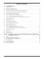
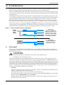
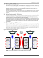
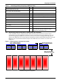
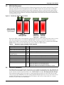
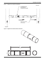
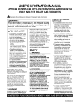
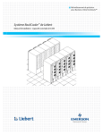
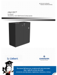
HEAT REMOVAL / PRECISION AIR
LIEBERT XD™ SYSTEM
SYSTEM DESIGN & CONFIGURATION
TABLE OF CONTENTS
1.0
SYSTEM DESCRIPTION . . . . . . . . . . . . . . . . . . . . . . . . . . . . . . . . . . . . . . . . . . . . . . . . . . . .1
1.1
XD Coolant™ . . . . . . . . . . . . . . . . . . . . . . . . . . . . . . . . . . . . . . . . . . . . . . . . . . . . . . . . . . . . . . . 1
2.0
DESIGNING AN XD SOLUTION . . . . . . . . . . . . . . . . . . . . . . . . . . . . . . . . . . . . . . . . . . . . . . .3
2.1
Determine Cooling Requirements and Select XD System . . . . . . . . . . . . . . . . . . . . . . . . . . . . 3
2.2
Calculate the Heat Load to be Handled by XD System . . . . . . . . . . . . . . . . . . . . . . . . . . . . . . 3
2.3
Selecting XDO or XDV Modules . . . . . . . . . . . . . . . . . . . . . . . . . . . . . . . . . . . . . . . . . . . . . . . . 4
2.4
Airflow Requirements for XD Solutions . . . . . . . . . . . . . . . . . . . . . . . . . . . . . . . . . . . . . . . . . . 4
2.4.1
2.4.2
Determining Spacing of XDOs in an Aisle . . . . . . . . . . . . . . . . . . . . . . . . . . . . . . . . . . . . . . . . . 4
Determining Vertical Placement of XDOs Above the Cold Aisle . . . . . . . . . . . . . . . . . . . . . . . . 5
2.5
XDV Unit Placement . . . . . . . . . . . . . . . . . . . . . . . . . . . . . . . . . . . . . . . . . . . . . . . . . . . . . . . . . 6
2.6
XDP/XDC Placement . . . . . . . . . . . . . . . . . . . . . . . . . . . . . . . . . . . . . . . . . . . . . . . . . . . . . . . . . 6
2.7
XD Piping System Design . . . . . . . . . . . . . . . . . . . . . . . . . . . . . . . . . . . . . . . . . . . . . . . . . . . . . 7
2.8
Other XD Piping Design Factors . . . . . . . . . . . . . . . . . . . . . . . . . . . . . . . . . . . . . . . . . . . . . . . . 8
2.9
Bypass Flow Controllers . . . . . . . . . . . . . . . . . . . . . . . . . . . . . . . . . . . . . . . . . . . . . . . . . . . . . . 8
2.10
Determining Coolant Volume . . . . . . . . . . . . . . . . . . . . . . . . . . . . . . . . . . . . . . . . . . . . . . . . . 10
2.10.1 XDP/XDC Pumped R-134a Circuit Volume. . . . . . . . . . . . . . . . . . . . . . . . . . . . . . . . . . . . . . . . 10
2.10.2 XDC DX R-407c Circuit Volume—Air Cooled Units. . . . . . . . . . . . . . . . . . . . . . . . . . . . . . . . . 11
2.11
Chilled Water Piping . . . . . . . . . . . . . . . . . . . . . . . . . . . . . . . . . . . . . . . . . . . . . . . . . . . . . . . . 11
2.12
Electrical . . . . . . . . . . . . . . . . . . . . . . . . . . . . . . . . . . . . . . . . . . . . . . . . . . . . . . . . . . . . . . . . . . 11
3.0
SPECIFICATIONS . . . . . . . . . . . . . . . . . . . . . . . . . . . . . . . . . . . . . . . . . . . . . . . . . . . . . . . .12
APPENDIX 1.0 GUIDELINES FOR LEAK TESTING AND FLUID REQUIREMENTS OF LIEBERT SYSTEMS
USING WATER OR GLYCOL . . . . . . . . . . . . . . . . . . . . . . . . . . . . . . . . . . . . . . . . . . 16
A 1.1 Scope. . . . . . . . . . . . . . . . . . . . . . . . . . . . . . . . . . . . . . . . . . . . . . . . . . . . . . . . . . . . . . . . . . . . . 16
A 1.2 General Guidelines and Information . . . . . . . . . . . . . . . . . . . . . . . . . . . . . . . . . . . . . . . . . . . . . 16
A 1.3 Checking Unit and Field Piping for Leaks . . . . . . . . . . . . . . . . . . . . . . . . . . . . . . . . . . . . . . . . . 16
A 1.4 Freeze Protection. . . . . . . . . . . . . . . . . . . . . . . . . . . . . . . . . . . . . . . . . . . . . . . . . . . . . . . . . . . . 17
A 1.5 Corrosion Protection . . . . . . . . . . . . . . . . . . . . . . . . . . . . . . . . . . . . . . . . . . . . . . . . . . . . . . . . . 17
A 1.6 System Maintenance . . . . . . . . . . . . . . . . . . . . . . . . . . . . . . . . . . . . . . . . . . . . . . . . . . . . . . . . . 17
i
FIGURES
Figure 1
Figure 2
Figure 3
Figure 4
Figure 5
Figure 6
Figure 7
Figure 8
Indirect and Direct system configuration . . . . . . . . . . . . . . . . . . . . . . . . . . . . . . . . . . . . . . . . . . . . .
XDO placement over cold aisle . . . . . . . . . . . . . . . . . . . . . . . . . . . . . . . . . . . . . . . . . . . . . . . . . . . . . .
XDO16 spacing—horizontal and vertical . . . . . . . . . . . . . . . . . . . . . . . . . . . . . . . . . . . . . . . . . . . . .
Positioning XDV on top of cabinet . . . . . . . . . . . . . . . . . . . . . . . . . . . . . . . . . . . . . . . . . . . . . . . . . . .
Piping for XDP/XDC used with XDO or XDV units . . . . . . . . . . . . . . . . . . . . . . . . . . . . . . . . . . . . .
Hydraulic schematic . . . . . . . . . . . . . . . . . . . . . . . . . . . . . . . . . . . . . . . . . . . . . . . . . . . . . . . . . . . . . .
Bypass flow controller arrangement . . . . . . . . . . . . . . . . . . . . . . . . . . . . . . . . . . . . . . . . . . . . . . . . .
Bypass flow controller details, dimensions . . . . . . . . . . . . . . . . . . . . . . . . . . . . . . . . . . . . . . . . . . . .
1
4
5
6
7
8
9
9
TABLES
Table 1
Table 2
Table 3
Table 4
Table 5
Table 6
Table 7
Table 8
Table 9
Table 10
Table 11
Table 12
Table 13
Calculating quantity and spacing of XDO16 modules . . . . . . . . . . . . . . . . . . . . . . . . . . . . . . . . . . . 5
Determine required number of XDV modules . . . . . . . . . . . . . . . . . . . . . . . . . . . . . . . . . . . . . . . . . . 6
Supply, return pipe sizes—equivalent lengths . . . . . . . . . . . . . . . . . . . . . . . . . . . . . . . . . . . . . . . . . 7
Bypass flow controllers required per XDO unit . . . . . . . . . . . . . . . . . . . . . . . . . . . . . . . . . . . . . . . . 8
Coolant volume calculations – XDP/XDC with XDV systems . . . . . . . . . . . . . . . . . . . . . . . . . . . . 10
Coolant volume calculation – XDP/XDC with XDO16 systems . . . . . . . . . . . . . . . . . . . . . . . . . . . 10
Indoor unit refrigerant charge—R-407C . . . . . . . . . . . . . . . . . . . . . . . . . . . . . . . . . . . . . . . . . . . . . 11
Outdoor condenser charge—R-407C . . . . . . . . . . . . . . . . . . . . . . . . . . . . . . . . . . . . . . . . . . . . . . . . 11
Liquid line charge - R-407C refrigerant per 100 ft (30 m) of Type "L" copper tube . . . . . . . . . . . 11
Liebert XDO16 specifications . . . . . . . . . . . . . . . . . . . . . . . . . . . . . . . . . . . . . . . . . . . . . . . . . . . . . . 12
Liebert XDC specifications . . . . . . . . . . . . . . . . . . . . . . . . . . . . . . . . . . . . . . . . . . . . . . . . . . . . . . . . 13
Liebert XDV specifications . . . . . . . . . . . . . . . . . . . . . . . . . . . . . . . . . . . . . . . . . . . . . . . . . . . . . . . . 14
Liebert XDP specifications . . . . . . . . . . . . . . . . . . . . . . . . . . . . . . . . . . . . . . . . . . . . . . . . . . . . . . . . 15
ii
System Description
1.0
SYSTEM DESCRIPTION
The Liebert XD™ family of cooling units delivers efficient, sensible cooling to high-heat environments, including computer racks and hot zones in a data center or computer room.
Systems combining XDO, XDV, XDP, XDC and XDA units can remove in excess of 500 watts of heat
per square foot. This heat removal capacity is achieved without sacrificing the Liebert XD units’ high
energy efficiency.
The XD family maintains this energy efficiency by employing the heat absorption properties of a liquid. Coolant is pumped as a liquid, becomes a gas within the heat exchangers of the cooling modules
(either the XDO or XDV) and then is returned to the pumping unit where it condenses to a liquid.
This eliminates the compression cycle required by traditional systems. And, if a leak were to occur,
the environmentally friendly coolant would escape as a gas, causing no harm to critical equipment.
Liebert XD systems are available in Direct and Indirect configurations—differentiated essentially
by the location of the pumping unit. The Indirect system uses a pumping unit to control and circulate
the XD Coolant™. In the Direct system, the pumping functions are incorporated in the chiller.
Figure 1
Indirect and Direct system configuration
Building
Chilled
Water
Supply
XDP
XDO or XDV
XDO or XDV
XDP
XDO or XDV
XDO or XDV
XDC
XDO or XDV
1.1
Indirect XD
System Configuration
XDPs pump coolant to XDO
and XDV modules, isolate
coolant from building chilled
water supply and maintains
coolant above dew point.
Direct XD
System Configuration
Pumping and control is
performed by chiller.
XD Coolant™
The coolant used in the XD system is HFC-134a (1,1,1,2-tetrafluoroethane), made by a number of
manufacturers. The amount of coolant used by the XD system may be significantly higher than typical DX cooling systems.
!
CAUTION
The XD pumped R-134a refrigerant circuits do not use refrigerant oil.
Do NOT put oil in the R-134a system.
All the major components of an XD system must be installed in a space with a volume of at least
1,000 ft3 (28.3m3) for each 16 pounds of coolant in that system from Table 1, ASHRAE Standard 152001, Safety Standard for Refrigeration Systems. If the XDP/XDC is placed in a separate area, such as
a machine room, then this area must also meet the volume requirement. Inside the critical space, this
includes the space under the raised floor, and the space between the top of the raised floor and the
bottom of a suspended ceiling. If the suspended ceiling is all open grates, then this additional space,
up to the overhead deck, would also be included.
Example
A space is 5,000 square feet, with an 18" raised floor and an 8' 6" suspended ceiling. XDOs and an
XDP are to be placed in this raised floor area.
The volume of the space is (1.5 + 8.5) x 5,000 or 50,000 cubic feet.
The maximum amount of coolant that can be used in a single XDP/XDC/XDO/XDV system within
this space is 16 * (50000/1000) = 16 * 50 = 800 lbs.
Multiple XD systems can be installed in this space, as long as the amount of coolant in any one
system does not exceed 800 lbs.
1
System Description
Liebert XDO—Overhead Cooling Module
The XDO ceiling-mounted cooling module draws in hot air rising from densely populated rack enclosures, passes it over the XDO’s coils and exhausts cooled air downward into the cold aisle.
Liebert XDV—Vertical Rack-Mounted Cooling Module
The XDV is installed on top of a rack enclosure. It can be set up in either of two ways:
• The XDV can take hot air from an equipment enclosure, cool the air and discharge it into the room
OR
• The XDV can draw hot air from the room, cool the air and discharge the cool air into the cold aisle.
Liebert XDP—Pumping Unit
The XDP isolates the building’s chilled water circuit from the XD Coolant™ circuit. Serving as an
intermediary in Indirect systems, the XDP circulates coolant to XDV or XDO modules while preventing condensation by maintaining the coolant’s temperature above the dew point.
Liebert XDC—Chiller
The XDC is an indoor chiller that connects directly to the XDO or XDV units and provides coolant circulation and control. The XDC keeps the XD Coolant fluid temperature above the dew point and eliminates the need for a separate pumping unit in the Direct system configuration.
Liebert XDA—Air Flow Enhancer
(Not covered in this System Configuration & Design document)
The XDA is a fan unit that boosts the airflow through densely populated enclosures, removing hot
spots from within the racks. One or two units can be mounted on most rack enclosures.
2
Designing an XD Solution
2.0
DESIGNING AN XD SOLUTION
Liebert XD systems are intended for use with precision air conditioning equipment, such as the Liebert Deluxe System/3. The precision air conditioning equipment is required to control the room’s
humidity and to filter the air.
The XD systems provide efficient, highly effective heat removal (sensible cooling only), and provide no
dehumidification. The XD control system maintains the coolant temperatures just above the dew
point of the space to prevent condensation. Since the capacity of the system is limited by the dew
point in the space, sufficient dehumidification and an adequate vapor barrier must be provided to
maintain the dew point at or below the level necessary to achieve the required capacity.
In their maximum density configurations, the XDO/XDV system can provide more than 500 watts per
square foot of cooling capacity. Peak loads in the immediate vicinity of an XD cooling module can be
higher. With precision cooling unit capacities in the range of 50 to 150 watts per square foot, the total
cooling density of an XD system combined with a precision cooling unit can be in excess of 700 watts
per square foot.
The Liebert XD system is optimized for hot aisle/cold aisle equipment configurations, the industry’s
most highly recommended method for dealing with extremely high heat loads.
Refer to the Deluxe System/3 Technical Data Manual (SL-18100) for additional installation and application guidelines that apply to all critical space cooling applications.
2.1
Determine Cooling Requirements and Select XD System
1.
2.
3.
4.
5.
2.2
Calculate the total cooling required
Determine placement of the XD units
Determine required pipe sizes
Calculate the coolant volume of the XD systems
Complete design details including, electrical, mounting, piping, etc.
Calculate the Heat Load to be Handled by XD System
When designing a cooling solution using the XD system, the initial steps are similar to those required
to cool a conventional critical space. The total heat load must be calculated, including sensible and
latent cooling requirements. These should be increased by the reserve capacity needed for pull-down
situations where the room temperature must be reduced and to provide for unexpected increases in
heat load.
NOTE
Reserve capacity is distinct from redundant capacity in that redundant capacity may or may
not be available concurrently with normal operating capacity. Reserve capacity is available
concurrently with normal operating capacity.
The next step is to determine how much of the required cooling capacity is to be provided by Liebert
Deluxe units. If the facility is new, up to 150 watts per square foot of cooling can be obtained from Liebert Deluxe units. In existing facilities, such factors as raised floor height, under-floor obstructions or
other limitations may reduce this to less than 50 watts per square foot.
Once the total required sensible cooling capacity is known, subtract the sensible cooling portion to be
provided by Liebert Deluxe units. This yields the cooling capacity to be provided by the XD system.
3
Designing an XD Solution
2.3
Selecting XDO or XDV Modules
The next step is to select XDO or XDV cooling modules to be configured into the solution. An XDO and
and an XDV cannot be connected to the same XDP/XDC. However, a complete extreme density cooling
solution can utilize XDO and XDV units connected to separate XDP/XDCs.
Generally, the XDO is selected for use in new installations or renovations where the unit can be
installed on the ceiling or in the overhead space.
The XDV is designed to permit mounting directly on top of an equipment cabinet, for ease of installation in existing facilities. The XDV may also be suspended from overhead, using suitable mounting
methods.
2.4
Airflow Requirements for XD Solutions
Computer manufacturers typically specify a temperature change from intake to exhaust (delta T) of
18-27°F (10-15°C) for the air passing through a rack enclosure. The heat generated by electronic
equipment combined with the tight quarters of equipment cabinets mean that high volumes of air
must move through an enclosure to meet this cooling specification.
An XD system can supply the cooled air to satisfy this cooling demand, but airflow through the enclosure must be adequate to extract the heat from the cabinet. Liebert’s XDA units can boost the airflow
to levels necessary to protect critical equipment. It is particularly suited to the hot aisle/cold aisle
arrangement.
2.4.1
Determining Spacing of XDOs in an Aisle
XDO units should be placed in rows directly above the cold aisles of a room for optimum cooling. Each
XDO serves an area equal in width to the cold aisle spacing (typically 12 to 16 feet [3.7 to 4.9m]). The
length of the area served includes any space between XDO modules in a row. Depending on the cooling capacity to be achieved, spacing between XDO modules in a row can vary from zero to as much as
6 feet (1.8m). When the spacing increases to more than 6 feet (1.8m), overall performance of the system may be negatively affected and gaps in cooling may occur.
Figure 2
XDO placement over cold aisle
XDO
XDO
Hot air is
drawn into
the XDO for
cooling
Critical
Equipment
Critical
Equipment
Critical
Equipment
Cooled air
enters the
rack...
Cooled air
enters the
rack...
Hot air goes
into the hot
aisle
COLD AISLE
Critical
Equipment
Hot air goes
into the hot
aisle
HOT AISLE
COLD AISLE
Cold Aisle
Spacing
Table 1 can be used to determine the correct number and spacing of XDOs.
4
Designing an XD Solution
Table 1
Calculating quantity and spacing of XDO16 modules
Input Information
Step
Total heat load in the room, kW
A
Reserve capacity needed
(10% to 25% of A is recommended)
B
Existing/planned Liebert Deluxe unit sensible capacity
D
C
Room area, square feet
Required cooling capacity = A + B
E
Required XD system cooling capacity = C – D
F
Number of XDOs required = E ÷ 16, rounded up
G
Number of XDPs required = F ÷ 10, rounded up
H
I
Spacing of cold aisles, center-to-center, typically 12-16 ft
(3.7 to 4.9m)
2.4.2
Result
Area served by each XDO = H ÷ F
J
K
Spacing between each XDO = (I ÷ J) - 2
L
Required XD system cooling density = E ÷ H
OK if under 640; otherwise, additional cooling is
required from Liebert Deluxe units.
Determining Vertical Placement of XDOs Above the Cold Aisle
In the maximum density configuration the XDOs should be placed between 18 and 24 inches
(457-609mm) above the equipment cabinets. In some cases where the required density is less, the
front-to-rear spacing of XDOs in a row will be increased. To ensure coverage of the wider spaces
between the XDO units, the vertical distance between the cabinets and the XDOs should be increased.
However, the recommended maximum height of the XDO above the cabinets is 30 inches. See
Figures 3.
Figure 3
XDO16 spacing—horizontal and vertical
Front-to-rear spacing of
pairs of XDO16 modules
Pairs of XDO16 modules
above critical equipment
XDO16 height above
equipment to be cooled
Heat-Generating Critical Equipment
5
Designing an XD Solution
2.5
XDV Unit Placement
XDV units should be placed on top of the cabinets that generate the greatest amount of heat. If heat
loads are dispersed evenly throughout the room, the XDV modules may be spread out accordingly.
The XDV must be placed toward the front of the equipment cabinet, so that its front bottom edge is
flush with the front top edge of the cabinet. Placing the unit farther back on the top of the unit will
restrict airflow into the cold aisle. Placing the unit farther to the front will decrease the amount of hot
air drawn into the unit.
Figure 4
Positioning XDV on top of cabinet
X
X
XDV is suspended
from roof structure;
separated from rack
by an air blocker
CORRECT
XDV is flush with
front edge of rack
INCORRECT
XDV is too
far from front
edge of rack
INCORRECT
XDV hangs
over front
edge of rack
Both of the XDV’s power cords should be connected to power sources. If only one power source is available, then only the power cord labeled “SECONDARY” should be connected to the power source.
Piping for the XDV is routed upward to the main return and supply pipes to and from the XDP/XDC.
Table 2 below can be used to determine the correct number of XDV modules.
Table 2
Determine required number of XDV modules
Input Information
Step
Total heat load in the room, kW
Reserve capacity needed
(10% to 25% of A is recommended)
A
B
C
Existing/planned Liebert Deluxe
sensible capacity
Room area, square feet
Required cooling capacity = A + B
D
E
F
G
H
I
L
2.6
Results
Required XD system cooling capacity = C – D
Number of XDV modules required = E ÷ 8, rounded up
Number of XDP/XDC modules required = F ÷ 20, rounded up
Area served by each XDV = H ÷ F
Required XD system cooling density = E ÷ H
OK if under 580 for 12-foot cold aisle spacing
OK if under 435 for 16-foot cold aisle spacing
Otherwise, additional Liebert Deluxe unit capacity is needed.
XDP/XDC Placement
The XDP/XDC may be placed in the critical space or in an adjacent equipment room. The allowable distance between the XDP/XDC and its connected cooling modules is determined by the piping design and
by the amount of coolant required. Refer to 1.1 - XD Coolant™ and 2.7 - XD Piping System Design.
The maximum height of any of the main or connecting piping should be no more than 20 feet (6m)
above the top of the XDP/XDC unit. XD cooling modules should be placed as close to the same level as
possible. The differences in elevation between the highest and lowest cooling module in a system
should be no more than 6 feet (609.6mm).
6
Designing an XD Solution
2.7
XD Piping System Design
All piping must be ASTM (American Society for Testing and Materials) Type L copper pipe.
Piping for the XD system is arranged in a manner similar to piping for a chilled water system. XDOs
or XDVs are connected in parallel between main return and supply pipes going to and from the XDP/
XDC. Figure 5 represents a typical configuration. The guidelines provided for pipe size must be
strictly followed. Failure to size the main lines and connection lines adequately may result
in reduced cooling capacity. The critical aspects of pipe sizing are related to coolant volume and
pressure drop. Both must be minimized.
Figure 5
Piping for XDP/XDC used with XDO or XDV units
XDO/XDV
XDP/
XDC
XDO/XDV
XDO/XDV
XDO/XDV
XDO/XDV
SLOPE—The main supply and return lines to and from the XDP/XDC must be
sloped downward toward the XDP/XDC at a rate of 1" per 10 feet (25.4mm per 3m)
of pipe run. Horizontal connector lines should also be sloped downward from the
cooling modules toward the main supply and return lines.
The assembly and connection means used for piping in the XD system are similar to that of conventional refrigeration systems. Brazing material or soft solder may be used. However, if brazing material is used, the lines being brazed MUST be pressurized with flowing dry nitrogen during brazing to
prevent excessive oxidation and scale formation inside the piping.
Please see Table 3 below for recommended pipe sizes and Figure 6 for piping segment locations.
Table 3
Supply, return pipe sizes—equivalent lengths
Pipe Function
Key to Piping
in Figure 6 Schematic
XDP/XDC supply line, from XDP/XDC
supply to farthest XDO16 or XDV
A
XDP/XDC return line, from XDP/XDC
return to farthest XDO16 or XDV
B
From XDO16 supply to supply line of
XDP/XDC
C
From XDO16 return to return line of
XDP/XDC
D
From XDV supply to supply line of
XDP/XDC
C
From XDV return to return line of
XDP/XDC
D
Size / Pipe Run
(Equivalent Lengths)
1-1/8" OD for lengths up to 60 feet
1-3/8" OD for lengths over 60 but less than 175 feet
2-1/8" OD for lengths up to 60 feet
2-5/8" OD for lengths over 60 but less than 175 feet
1/2" OD for lengths up to 10 feet
7/8" OD for lengths over 10 but less than 25 feet
7/8" OD for lengths up to 10 feet
1-1/8" OD for lengths over 10 but less than 25 feet
1/2" OD for lengths up to 6 feet
5/8" OD for lengths over 6 but less than 35 feet
5/8" OD for lengths up to 6 feet
7/8" OD for lengths over 6 but less than 35 feet
For additional information about piping connections, see the unit’s user manual: XDP, 16641;
XDC, SL-16671; XDO16, SL-16661; and XDV, SL-16621.
!
CAUTION
To minimize the amount of XD Coolant required, do NOT oversize the piping.
7
Designing an XD Solution
Figure 6
Hydraulic schematic
Building
Chilled
Water
Supply
A
XDP/XDC
B
C
D
XD Coolant
Piping
C
A
C
XDP/XDC
B
D
D
XDO or XDV
XDO or XDV
Supply
Lines
Return
Lines
XDO or XDV
XDPs pump coolant to XDO and XDV modules,
isolate coolant from building chilled water supply
2.8
Other XD Piping Design Factors
• Slope—The main supply and return lines to and from the XDP/XDC must be sloped downward
toward the XDP/XDC at a rate of 1" per 10 feet (25.4mm per 3m) of pipe run. Horizontal connector
lines should also be sloped downward from the cooling modules toward the main supply and
return lines.
• Insulation—All piping (XD Coolant and Chilled Water) should be insulated.
2.9
Bypass Flow Controllers
To ensure the XDP/XDC pumps operate within the optimum range, some installations require one or
more bypass flow controller(s). These devices are added to the field piping, and simulate the flow of
additional cooling modules.
Each bypass flow controller should be installed with one shutoff valve to allow the controller to be disabled when cooling modules are added to an XD system.
Bypass flow controllers may be placed anywhere in the field piping but should be placed in a convenient, accessible location. Piping details of the bypass flow controller are shown in Figures 7 and 8.
Refer to Table 4 to determine the number of bypass flow controllers needed, based on the total nominal cooling capacity of the cooling modules in each XD system.
Table 4
Bypass flow controllers required per XDO unit
Number, Size of
XDO/XDV Units
Bypass Flow
Controllers
XDV8*
4-11
2
12-15
1
16-20
0
XDO16**
2-5
*
*
**
**
2
6-7
1
8-10
0
Minimum of four XDV8s required for XDP-based systems
Minimum of eight XDV8s required for XDC-based systems
Minimum of two XDO16s required for XDP-based systems
Minimum of four XDO16s required for XDC-based systems
8
Designing an XD Solution
Figure 7
Bypass flow controller arrangement
7/8” Refrigerant Grade
Full Port Ball Valve
Field-Supplied and Installed
Flow Direction
Bypass Flow Controller
(Field-Installed)
Supply Main
Figure 8
Bypass flow controller details, dimensions
4”
(102mm)
7/8”
(2.2mm) ID
9
Return Main
Designing an XD Solution
2.10
Determining Coolant Volume
After the preliminary system design is completed, Tables 5, through 9 may be used to determine the
amount of coolant required. Perform the calculation below for each XD system being configured.
NOTE
All lengths in the tables below—Tables 5 and 6 —are actual pipe lengths, not equivalent pipe
lengths
2.10.1 XDP/XDC Pumped R-134a Circuit Volume
Table 5
Coolant volume calculations – XDP/XDC with XDV systems
145 lbs. R-134a per XDP (includes charge of one XDP while running)
+1.46 lbs. R-134a per XDV (does not include piping connector lines to and from XDV)
0.45 lbs. per foot of main supply actual length per 1-1/8" OD copper tubing
0.68 lbs. per foot of main supply actual length per 1-3/8" OD copper tubing
0.28 lbs. per foot of main return actual length per 2-1/8" OD copper tubing
0.43 lbs. per foot of main return actual length per 2-5/8" OD copper tubing
0.08 lbs. per foot of 1/2" OD copper tubing XDV supply connector actual length
0.13 lbs. per foot of 5/8" OD copper tubing XDV supply connector actual length
0.02 lbs. per foot of 5/8" OD copper tubing XDV return connector actual length
0.04 lbs. per foot of 7/8" OD copper tubing XDV return connector actual length
= Amount of XD Coolant needed for ONE XDV/XDP system
Table 6
Coolant volume calculation – XDP/XDC with XDO16 systems
145 lbs. R-134a per XDP (includes charge of one XDP while running)
+2.92 lbs. R-134a per XDO16 (does not include piping connector lines to and from XDO16)
0.45 lbs. per foot of main supply actual length per 1-1/8" OD copper tubing
0.68 lbs. per foot of main supply actual length per 1-3/8" OD copper tubing
0.28 lbs. per foot of main return actual length per 2-1/8" OD copper tubing
0.43 lbs. per foot of main return actual length per 2-5/8" OD copper tubing
0.08 lbs. per foot of 1/2" OD XDO supply connector actual length
0.26 lbs. per foot of 7/8" OD XDO supply connector actual length
0.04 lbs. per foot of 7/8" OD copper tubing XDO16 return connector actual length
0.07 lbs. per foot of 1-1/8" OD copper tubing XDO16 return connector actual length
= Amount of XD Coolant needed for ONE XDO16/XDP system
Verify that the coolant volume of the XD system with the longest piping length is within the allowable
limit. If the allowable limit is exceeded, the XDP must be moved closer to the cooling modules.
10
Designing an XD Solution
2.10.2 XDC DX R-407c Circuit Volume—Air Cooled Units
Weigh in the calculated charge based on Tables 7, 8 and 9..
Table 7
Indoor unit refrigerant charge—R-407C
Model 60 Hz
Charge/Circuit lb. (kg)
XDC160
4.5 (2.0)
Table 8
Outdoor condenser charge—R-407C
Model
Charge / Circuit, lb (kg)
CDL830
182 (82.6)
CSL616
254 (115.2)
Table 9
2.11
Liquid line charge - R-407C refrigerant per 100 ft (30 m) of Type "L" copper tube
O.D.,
inches
Liquid Line,
lb (kg)
Hot Gas Line,
lb (kg)
3/8
3.7 (1.7)
-
1/2
6.9 (3.1)
-
5/8
11.0 (5.0
2.2 (1.0)
3/4
15.7 (7.1)
3.1 (1.4)
7/8
23.0 (10.4)
4.5 (2.0)
1-1/8
39.3 (17.8)
7.8 (3.5)
1-3/8
59.8 (27.1
11.8 (5.4)
1-5/8
-
16.7 (7.6)
Chilled Water Piping
The XDP is offered only with a two-way chilled water control valve. Some applications may require
the use of a pressure activated bypass valve, to prevent dead-heading of the chilled water pump. This
bypass valve must be specified by the engineer responsible for design of the chilled water field piping
system.
Chilled water connections to the XDP are near the bottom of the unit. Refer to the XDP user manual
(SL-16641) for further information. Piping is routed downward from the unit to chilled water piping
under the raised floor. Connections are made using standard practices for copper chilled water piping.
Victaulic® connections may be used to simplify installation in existing facilities. Refer to Table 13
and Appendix 1.0 - Guidelines for Leak Testing and Fluid Requirements of Liebert Systems
Using Water or Glycol for additional information.
2.12
Electrical
Electrical service shall conform to national and local electrical codes. Make all wiring and electrical
connections in accordance with local and national codes. Refer to equipment nameplate regarding
wire size and circuit protection requirements. Refer to electrical schematic when making connections.
11
Specifications
3.0
SPECIFICATIONS
This document contains preliminary technical information for Liebert’s XDO, XDV and XDP/XDC.
For technical data about other units in the Liebert XD product family—RackCooler (XDR),
CDU (XDWP) and Air Flow Enhancer (XDA)—see separate user manuals and system configuration
guides.
Table 10
Liebert XDO16 specifications
Number of Models
4, based on input voltage and optional condensate sensing
Cooling Capacity, nominal
16 kW / 4.6 Tons @ 55ºF (13ºC) Entering Coolant Temperature, 85ºF
(30ºC) Entering Air Temperature, 50ºF (10ºC) or lower dew point
Electrical Requirements
Input Voltage
1ph-60Hz-120V
Input wiring configuration
120V Line, Neutral Ground
Input Power Connections
Terminal blocks provided on unit
Full Load Amps
Power consumption, nominal
Power, optional lighting fixture
3.1A @ 120V
374 Watts
0.9A per 120V light fixture; 0.4A per 277V light fixture
Dimensions, inches (mm)
Width
72 (1828.8)
Depth
24 (609.6)
Height
22-1/2 (571.5)
Weight, lbs (kg)
Unit only
Shipping weight
Installed, with coolant, without options
Number of Fans
238 (108)
155 (70)
1
Audible noise
Airflow, nominal,
150 (68)
84 dBa sound power at full fan speed
ft3/
min
(m3/
hr)
2700 (4587)
Pipe connections
XD Coolant Supply from XDP/XDChiller
1/2" OD, Cu
XD Coolant Return to XDP/XDChiller
7/8" OD, Cu
Serviceable Parts
Exterior finish – bottom, sides, front
and rear
Fan and electrical components
Black, matte finish, heat-fused powder coat
Exterior finish - top
Hot-dipped galvanized steel
Options
Lighting fixtures (ship loose)
Condensate sensing (factory-installed)
2 XDO16s per lighting unit; 120V or 277V; 4' standard fluorescent tubes
(not provided)
Dry contact outgoing signal
12
Specifications
Table 11
Liebert XDC specifications
46 tons / 160kW with 125ºF (51.6ºC) condensing temperature and 50ºF
(10ºC) evaporating temperature
Cooling Capacity, Nominal
Electrical Requirements
Input
Full Load Amps
460V model: 3 phase, 60 Hz
460V model: 79A
Minimum supply wire sizing ampacity
84A
Maximum fuse or circuit breaker size
100A
Dimensions, inches (mm)
Height – Unit only
78 (1981)
Height – As shipped
83 (2108)
Width
74 (1879)
Depth
34 (863)
Weight, lb (kg)
Unit only
2000 (907)
Shipping weight
2050 (930)
Installed, with R-134a
2200 (998)
Pipe Connections
XD Coolant supply to XDO or XDV
1-1/8" OD, Cu
XD Coolant return from XDO or XDV
2-1/8" OD, Cu
Liquid Line (DX circuit)
Hot Gas Line (DX circuit)
7/8" OD, Cu
1-3/8" OD, Cu
Number of XDOs Connected
Maximum,10; Minimum, 4
Number of XDVs Connected
Maximum, 20; Minimum, 8
Cabinet Exterior Finish
Black, matte finish, heat-fused powder coat
13
Specifications
Table 12
Liebert XDV specifications
Number of models
4, based on input voltage and optional condensate sensing
Cooling capacity, nominal
8 kW / 2.2 Tons @ 55ºF (13ºC) Entering Coolant Temperature, 90ºF
(32ºC) Entering Air Temperature, 50ºF (10ºC) or lower dew point, rear
inlet.
Electrical requirements
Input
Input power connections
Full Load Amps
Power consumption, nominal
120V model: 1ph-50/60 Hz
230V model: 1ph-50/60 Hz
120V model: 2 power cords, NEMA 5-15P plugs
230V model: 2 power cords, IEC320-C14 plugs
120V model: 2.0 A
230V model: 1.0 A
200 Watts
Dimensions, inches (mm)
Height – unit only
14-1/8 (359) not including pipe connections
Height – including pipe connections
18-3/4 (476)
Width
23-1/2 (597)
Depth – Top
Depth – Bottom
39-1/2 (1003)
29-1/2 (749)
Weight, lbs (kg)
Unit only
Shipping weight
Installed, with coolant
77 (35)
125 (57)
79 (36)
Number of fans
2
Audible noise
78 dBa sound power (both fans running)
Pipe connections
XD Coolant supply from XDP/XDChiller
1/2" OD, Cu
XD Coolant return to XDP/XDChiller
5/8" OD, Cu
Airflow, nominal, ft3/ min (m3/ hr)
1000 (1699) with rear inlet. Bottom inlet airflow may be less depending
on restrictions inside cabinet
Serviceable parts
Fans and electrical components
Cabinet exterior finish
Black, matte finish, heat-fused powder coat
Options
Condensate sensing (factory-installed)
Dry contact outgoing signal
14
Specifications
Table 13
Liebert XDP specifications
Number of models
4, based on input voltage and pump redundancy
Cooling capacity, nominal
160 kW / 46 Tons with 45ºF (7ºC) entering water temperature and
140gpm (530lpm) water flow rate. Capacity is reduced when glycol
mixtures are used in place of 100% water.
Electrical requirements
Input
Full Load Amps
208V model: 3-phase, 60 Hz
460V model: 3 phase, 60 Hz
208V model: 4 Amps
460V model: 2.1 Amps
Dimensions, inches (mm)
Height – Unit only
Height – As shipped
76 (1930) does not include pipe connections
83 (2108)
Width
37 (940)
Depth
30 (762)
Weight, lbs (kg)
Unit only
855 (388)
Shipping weight
960 (435)
Installed, with coolant and chilled water
1025 (465)
Pipe connections
XD Coolant supply to XDO or XDV
1-1/8" OD, Cu
XD Coolant return from XDO or XDV
2-1/8" OD, Cu
Chilled water supply and return
2-5/8" OD, Cu
Control valve
2-way, 2" nominal
Pressure drop – chilled water side
20 PSIG, with 140 gpm (530lpm) water flow rate, control valve fully open
Temperature rise – chilled water
side, F (C)
8.0° (4.4°) with rated flow
Number of XDOs connected
Maximum 10; minimum 2 (for XDO16)
Number of XDVs connected
Maximum 20; Minimum 4
Cabinet exterior finish
Black, matte finish, heat-fused powder coat
15
Guidelines for Leak Testing and Fluid Requirements of Liebert Systems Using Water or Glycol
APPENDIX 1.0 GUIDELINES FOR LEAK TESTING AND FLUID REQUIREMENTS OF
LIEBERT SYSTEMS USING WATER OR GLYCOL
A 1.1 Scope
These guidelines apply to the field leak checking and fluid requirements for field piping systems that
include Liebert chilled water, hot water, condenser (water or glycol), GLYCOOL and drycooler circuits.
A 1.2 General Guidelines and Information
• Equipment damage and personal injury can result from improper piping installation, leak checking, fluid chemistry and fluid maintenance.
• Follow local piping codes, safety codes, and Liebert unit installation and maintenance instructions.
• Qualified personnel must install and inspect system piping.
• Contact a local water consultant regarding water quality, corrosion protection and freeze protection requirements.
• Units may be shipped with a nitrogen holding charge.
A 1.3 Checking Unit and Field Piping for Leaks
Liebert units’ fluid systems are checked at the factory for leaks, but the unit’s fluid circuits and fieldinstalled piping should be checked at installation for leaks.
Liebert recommends following these guidelines for testing a Liebert unit for leaks:
A 1.3.1 Leak Check—XDP Chilled Water Side
• Isolate the unit using field-installed shutoff valves
• Use fluid for pressure testing if possible (dry seals in fluid valves and pumps may not hold a high
gas pressure)
If not using liquid for pressure testing:
• The maximum recommended pressure is 30 psig (2 bars) of dry nitrogen.
• Verify the system’s tightness by either pressure decay over time,
(<2 psig/hour [0.3 bars/hour]) —OR—sensing a tracer gas with suitable instrumentation
A 1.3.2 Leak Check—XDP/XDC R-134a Pumped Circuit
1. Open all service valves.
2. Place a maximum of 150 PSIG (1034 kPa) of dry nitrogen with a tracer of R-134a in the system.
3. Check the system for leaks.
A 1.3.3 Leak Check—XDC R-407c (DX) Circuit
1. Make sure the unit is Off. Open all disconnects and pull all fuses except the control fuses. On
units supplied with circuit breakers, open all breakers except for the transformer.
2. Energize the liquid line solenoid valves via 24VAC or through Diagnostics under “Test Outputs,”
select DEHYDRATION to be On. This will energize the solenoids and hot gas valves to open
simultaneously on Circuit 1 and Circuit 2.
NOTE
The procedures above allow the technician to use 24VAC power and controls to open liquid line
solenoid valve(s) for the dehydration process. If no power is at the unit disconnect, the
technician is to use a separate 24VAC source rated at 75 VA and connect to the system liquid
line solenoid valve(s) directly.
3. Attach a jumper hose to the suction and discharge service valves of the compressor. Open all
compressor service valves.
4. Connect the tank of dry nitrogen to the Schrader valves on the liquid lines and the hot gas lines.
5. Pressurize the system circuit(s) to 150 PSIG (1034 kPa) with dry nitrogen with a trace of
refrigerant. Check the system for leaks with a suitable leak finder.
16
Guidelines for Leak Testing and Fluid Requirements of Liebert Systems Using Water or Glycol
A 1.4 Freeze Protection
!
CAUTION
Cooling units and their pipes must be protected if they might be exposed to freezing
temperatures. This is required even for units taken out of service and placed in storage. Some
liquid will remain in the system even after rigorous attempts to drain the units.
When the field piping or unit might be exposed to freezing temperatures, charge the system with the
proper percentage of glycol and water for the coldest design ambient temperature. This is required to
protect the system piping and unit from freezing and rupturing. Some liquids will remain in the systems, even after they are drained and might freeze without the proper water and glycol mixture.
Automotive antifreeze is unacceptable and must NOT be used in any glycol fluid system.
A 1.5 Corrosion Protection
Liebert systems contain iron and copper alloys that require protection from corrosion. Contact a local
water consultant regarding water quality, corrosion and freeze-protection requirements.
Read and follow individual unit installation instructions for precautions regarding fluid system
design, material selection and use of field-provided devices.
Water chemistry varies greatly by location, as do the required additives, called inhibitors, that reduce
the corrosive effect of the fluids on the piping systems and components. The chemistry of the water
used must be considered because water from some sources may contain corrosive elements that
reduce the effectiveness of the inhibitors.
Surface waters that are classified as soft and are low in chloride and sulfate ion content should be
used, if at all possible. Proper inhibitor maintenance must be performed to prevent corrosion of the
system. Consult the manufacturer of the glycol used for testing and maintenance of inhibitors.
Commercial ethylene glycol, (Union Carbide Ucartherm, Dow Chemical Dowtherm SR-1 and
Texaco E. G. Heat Transfer Fluid 100) when pure, is generally less corrosive to the common metals of
construction than water itself. Ethylene glycol will, however, assume the corrosivity of the water with
which it is prepared and may become increasingly corrosive with use if not properly treated with
inhibitors.
Keep the unit switched ON and the system pump operating. Idle fluid allows the collection of sediment, which prevents the formation of a protective oxide layer on the inside of tubes.
A 1.6 System Maintenance
Establish and follow a schedule for checking the Liebert unit and system for fluid leaks and proper
fluid chemistry.
Fluid system quality remains a requirement throughout the life of the piping system. System fluid
conditions must be evaluated on a maintenance schedule and treated to provide a stable fluid chemistry in any piping loop that contains iron and copper alloys.
17
Guidelines for Leak Testing and Fluid Requirements of Liebert Systems Using Water or Glycol
18
HEAT REMOVAL / PRECISION AIR
Liebert XD™ Cooling Units
SYSTEM DESIGN & CONFIGURATION
The Company Behind the Products
With over a million installations around the globe,
Liebert is the world leader in computer protection
systems. Since its founding in 1965, Liebert has
developed a complete range of support and
protection systems for sensitive electronics:
•
•
•
•
•
Environmental systems—close-control air
conditioning from 1 to 60 tons
Power conditioning and UPS with power
ranges from 300 VA to more than 1000 kVA
Integrated systems that provide both
environmental and power protection in a
single, flexible package
Monitoring and control—from systems of any
size or location, on-site or remote
Service and support through more than 100
service centers around the world and a 24/7
Customer Response Center
While every precaution has been taken to ensure
the accuracy and completeness of this literature,
Liebert Corporation assumes no responsibility and
disclaims all liability for damages resulting from
use of this information or for any errors or
omissions.
© 2005 Liebert Corporation
All rights reserved throughout the world.
Specifications subject to change without notice.
® Liebert and the Liebert logo are registered
trademarks of Liebert Corporation. All names
referred to are trademarks or registered
trademarks of their respective owners.
SL-16650 (01/05) Rev. 5
Technical Support/Service
Web Site
www.liebert.com
Monitoring
800-222-5877
[email protected]
Outside the US: 614-841-6755
Single-Phase UPS
800-222-5877
[email protected]
Outside the US: 614-841-6755
Three-Phase UPS
800-543-2378
[email protected]
Environmental Systems
800-543-2778
Outside the United States
614-888-0246
Locations
United States
1050 Dearborn Drive
P.O. Box 29186
Columbus, OH 43229
Italy
Via Leonardo Da Vinci 8
Zona Industriale Tognana
35028 Piove Di Sacco (PD)
+39 049 9719 111
Fax: +39 049 5841 257
Asia
23F, Allied Kajima Bldg.
138 Gloucester Road
Wanchai
Hong Kong
+852 2 572 2201
Fax: +852 2 831 0114