1
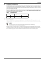
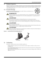
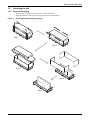
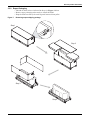
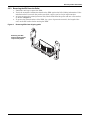
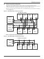
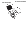
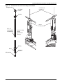
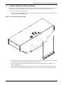
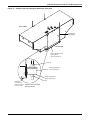
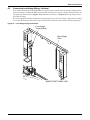
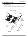
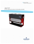
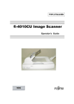
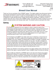
Precision Cooling for
Business Critical Continuity
Liebert XDO™
User Manual
14 & 16kW Nominal Capacity, 50 & 60 Hz
TABLE OF CONTENTS
1.0
XDO COMPONENT LOCATIONS AND MODEL NUMBER NOMENCLATURE . . . . . . . . . . . . . . . .1
2.0
INSTALLATION . . . . . . . . . . . . . . . . . . . . . . . . . . . . . . . . . . . . . . . . . . . . . . . . . . . . . . . . . .2
2.1
References . . . . . . . . . . . . . . . . . . . . . . . . . . . . . . . . . . . . . . . . . . . . . . . . . . . . . . . . . . . . . . . . . . 2
2.2
Pre-Installation Checks . . . . . . . . . . . . . . . . . . . . . . . . . . . . . . . . . . . . . . . . . . . . . . . . . . . . . . . 2
2.3
Parts Included With XDO . . . . . . . . . . . . . . . . . . . . . . . . . . . . . . . . . . . . . . . . . . . . . . . . . . . . . 2
2.3.1
2.4
Optional Items . . . . . . . . . . . . . . . . . . . . . . . . . . . . . . . . . . . . . . . . . . . . . . . . . . . . . . . . . . . . . . . 2
Installation Considerations . . . . . . . . . . . . . . . . . . . . . . . . . . . . . . . . . . . . . . . . . . . . . . . . . . . . 3
2.4.1
Room Preparation. . . . . . . . . . . . . . . . . . . . . . . . . . . . . . . . . . . . . . . . . . . . . . . . . . . . . . . . . . . . . 3
3.0
GENERAL PRODUCT INFORMATION . . . . . . . . . . . . . . . . . . . . . . . . . . . . . . . . . . . . . . . . . . .4
3.1
Product/System Description . . . . . . . . . . . . . . . . . . . . . . . . . . . . . . . . . . . . . . . . . . . . . . . . . . . 4
3.2
Introduction . . . . . . . . . . . . . . . . . . . . . . . . . . . . . . . . . . . . . . . . . . . . . . . . . . . . . . . . . . . . . . . . 4
3.3
Equipment Inspection . . . . . . . . . . . . . . . . . . . . . . . . . . . . . . . . . . . . . . . . . . . . . . . . . . . . . . . . 5
3.3.1
Recyclable Packaging . . . . . . . . . . . . . . . . . . . . . . . . . . . . . . . . . . . . . . . . . . . . . . . . . . . . . . . . . . 5
3.4
Unit Handling. . . . . . . . . . . . . . . . . . . . . . . . . . . . . . . . . . . . . . . . . . . . . . . . . . . . . . . . . . . . . . . 5
3.5
Unpacking the Unit . . . . . . . . . . . . . . . . . . . . . . . . . . . . . . . . . . . . . . . . . . . . . . . . . . . . . . . . . . 6
3.5.1
3.5.2
3.5.3
Domestic Packaging . . . . . . . . . . . . . . . . . . . . . . . . . . . . . . . . . . . . . . . . . . . . . . . . . . . . . . . . . . . 6
Export Packaging . . . . . . . . . . . . . . . . . . . . . . . . . . . . . . . . . . . . . . . . . . . . . . . . . . . . . . . . . . . . . 7
Removing the XDO from the Pallet . . . . . . . . . . . . . . . . . . . . . . . . . . . . . . . . . . . . . . . . . . . . . . . 8
4.0
MECHANICAL CONSIDERATIONS . . . . . . . . . . . . . . . . . . . . . . . . . . . . . . . . . . . . . . . . . . . . 10
4.1
Locating in Ceiling, Spacing . . . . . . . . . . . . . . . . . . . . . . . . . . . . . . . . . . . . . . . . . . . . . . . . . . 10
4.1.1
Weight Distribution . . . . . . . . . . . . . . . . . . . . . . . . . . . . . . . . . . . . . . . . . . . . . . . . . . . . . . . . . . 10
4.2
Leveling. . . . . . . . . . . . . . . . . . . . . . . . . . . . . . . . . . . . . . . . . . . . . . . . . . . . . . . . . . . . . . . . . . . 10
4.3
Ceiling Preparation . . . . . . . . . . . . . . . . . . . . . . . . . . . . . . . . . . . . . . . . . . . . . . . . . . . . . . . . . 10
4.4
System Connection Configuration . . . . . . . . . . . . . . . . . . . . . . . . . . . . . . . . . . . . . . . . . . . . . . 11
5.0
ATTACHING SUSPENSION HARDWARE AND MOUNTING THE UNIT . . . . . . . . . . . . . . . . . . . . 12
5.1
Opening Hinged, Removable Fan Tray . . . . . . . . . . . . . . . . . . . . . . . . . . . . . . . . . . . . . . . . . . 12
5.2
Installation With Internal Mounting Brackets . . . . . . . . . . . . . . . . . . . . . . . . . . . . . . . . . . . 14
5.3
Installation With External Mounting Brackets . . . . . . . . . . . . . . . . . . . . . . . . . . . . . . . . . . . 16
6.0
ELECTRICAL CONNECTIONS . . . . . . . . . . . . . . . . . . . . . . . . . . . . . . . . . . . . . . . . . . . . . . . 18
6.1
Connecting High Voltage Cables . . . . . . . . . . . . . . . . . . . . . . . . . . . . . . . . . . . . . . . . . . . . . . . 18
6.2
Connecting Low Voltage Wiring—Optional . . . . . . . . . . . . . . . . . . . . . . . . . . . . . . . . . . . . . . 21
7.0
PIPING CONNECTIONS AND PIPING ACCESS POINTS . . . . . . . . . . . . . . . . . . . . . . . . . . . . . 22
7.1
Connection Methods and Points . . . . . . . . . . . . . . . . . . . . . . . . . . . . . . . . . . . . . . . . . . . . . . . 22
7.2
Piping Details - Shutoff/Isolation Valves . . . . . . . . . . . . . . . . . . . . . . . . . . . . . . . . . . . . . . . . 24
7.3
Connecting Pipes to the Top of the XDO. . . . . . . . . . . . . . . . . . . . . . . . . . . . . . . . . . . . . . . . . 25
7.4
Connecting Pipes Through the Side or Front of the XDO . . . . . . . . . . . . . . . . . . . . . . . . . . . 25
i
7.5
Holding Charge. . . . . . . . . . . . . . . . . . . . . . . . . . . . . . . . . . . . . . . . . . . . . . . . . . . . . . . . . . . . . 25
7.6
Brazing Preparations . . . . . . . . . . . . . . . . . . . . . . . . . . . . . . . . . . . . . . . . . . . . . . . . . . . . . . . . 25
7.7
Recommended Piping Size . . . . . . . . . . . . . . . . . . . . . . . . . . . . . . . . . . . . . . . . . . . . . . . . . . . . 25
7.8
Insulation . . . . . . . . . . . . . . . . . . . . . . . . . . . . . . . . . . . . . . . . . . . . . . . . . . . . . . . . . . . . . . . . . 26
7.9
Charging with Refrigerant and Starting the XD System . . . . . . . . . . . . . . . . . . . . . . . . . . . 26
8.0
MOUNTING OPTIONAL LIGHT UNITS . . . . . . . . . . . . . . . . . . . . . . . . . . . . . . . . . . . . . . . . . .27
9.0
CHECKLIST FOR PROPER INSTALLATION . . . . . . . . . . . . . . . . . . . . . . . . . . . . . . . . . . . . . .28
10.0
MAINTENANCE . . . . . . . . . . . . . . . . . . . . . . . . . . . . . . . . . . . . . . . . . . . . . . . . . . . . . . . . . 29
11.0
SPECIFICATIONS . . . . . . . . . . . . . . . . . . . . . . . . . . . . . . . . . . . . . . . . . . . . . . . . . . . . . . . .30
FIGURES
Figure 1
Figure 2
Figure 3
Figure 4
Figure 5
Figure 6
Figure 7
Figure 8
Figure 9
Figure 10
Figure 11
Figure 12
Figure 13
Figure 14
Figure 15
Figure 16
Figure 17
Figure 18
Figure 19
Figure 20
Figure 21
Figure 22
Figure 23
Figure 24
Figure 25
Figure 26
XDO component locations. . . . . . . . . . . . . . . . . . . . . . . . . . . . . . . . . . . . . . . . . . . . . . . . . . . . . . . . . . 1
Model number nomenclature . . . . . . . . . . . . . . . . . . . . . . . . . . . . . . . . . . . . . . . . . . . . . . . . . . . . . . . 1
Generic air flow schematic . . . . . . . . . . . . . . . . . . . . . . . . . . . . . . . . . . . . . . . . . . . . . . . . . . . . . . . . . 4
Generic piping schematic . . . . . . . . . . . . . . . . . . . . . . . . . . . . . . . . . . . . . . . . . . . . . . . . . . . . . . . . . . 4
Recommended unit handling equipment . . . . . . . . . . . . . . . . . . . . . . . . . . . . . . . . . . . . . . . . . . . . . . 5
Removing domestic shipping package . . . . . . . . . . . . . . . . . . . . . . . . . . . . . . . . . . . . . . . . . . . . . . . . 6
Removing export shipping package . . . . . . . . . . . . . . . . . . . . . . . . . . . . . . . . . . . . . . . . . . . . . . . . . . 7
Removing XDO from shipping pallet . . . . . . . . . . . . . . . . . . . . . . . . . . . . . . . . . . . . . . . . . . . . . . . . . 8
General arrangement and overall dimensions . . . . . . . . . . . . . . . . . . . . . . . . . . . . . . . . . . . . . . . . . 9
Typical XDO piping—interlaced connections . . . . . . . . . . . . . . . . . . . . . . . . . . . . . . . . . . . . . . . . . 11
Typical XDO piping—non-interlaced connection . . . . . . . . . . . . . . . . . . . . . . . . . . . . . . . . . . . . . . 11
Opening or removing hinged fan tray . . . . . . . . . . . . . . . . . . . . . . . . . . . . . . . . . . . . . . . . . . . . . . . 12
Fan tray opened for access . . . . . . . . . . . . . . . . . . . . . . . . . . . . . . . . . . . . . . . . . . . . . . . . . . . . . . . . 13
Mounting hole locations . . . . . . . . . . . . . . . . . . . . . . . . . . . . . . . . . . . . . . . . . . . . . . . . . . . . . . . . . . 14
Threaded rod and internal mounting kit installation. . . . . . . . . . . . . . . . . . . . . . . . . . . . . . . . . . . 15
External mounting kit for XDO . . . . . . . . . . . . . . . . . . . . . . . . . . . . . . . . . . . . . . . . . . . . . . . . . . . . 16
Detailed view of mounting kit attached to front panel . . . . . . . . . . . . . . . . . . . . . . . . . . . . . . . . . . 17
XDO electrical connection diagram . . . . . . . . . . . . . . . . . . . . . . . . . . . . . . . . . . . . . . . . . . . . . . . . . 18
Top and front electrical access points . . . . . . . . . . . . . . . . . . . . . . . . . . . . . . . . . . . . . . . . . . . . . . . 19
High-voltage terminal block location and connection locations . . . . . . . . . . . . . . . . . . . . . . . . . . . 20
Low voltage wiring connections . . . . . . . . . . . . . . . . . . . . . . . . . . . . . . . . . . . . . . . . . . . . . . . . . . . . 21
Top piping access points . . . . . . . . . . . . . . . . . . . . . . . . . . . . . . . . . . . . . . . . . . . . . . . . . . . . . . . . . . 22
Front piping access points . . . . . . . . . . . . . . . . . . . . . . . . . . . . . . . . . . . . . . . . . . . . . . . . . . . . . . . . 23
Side piping access points . . . . . . . . . . . . . . . . . . . . . . . . . . . . . . . . . . . . . . . . . . . . . . . . . . . . . . . . . 23
Piping details. . . . . . . . . . . . . . . . . . . . . . . . . . . . . . . . . . . . . . . . . . . . . . . . . . . . . . . . . . . . . . . . . . . 24
Adding optional lighting units . . . . . . . . . . . . . . . . . . . . . . . . . . . . . . . . . . . . . . . . . . . . . . . . . . . . . 27
TABLES
Table 1
Table 2
Table 3
Table 4
Application limits . . . . . . . . . . . . . . . . . . . . . . . . . . . . . . . . . . . . . . . . . . . . . . . . . . . . . . . . . . . . . . . . 3
Branch piping . . . . . . . . . . . . . . . . . . . . . . . . . . . . . . . . . . . . . . . . . . . . . . . . . . . . . . . . . . . . . . . . . . 25
Liebert XDO specifications . . . . . . . . . . . . . . . . . . . . . . . . . . . . . . . . . . . . . . . . . . . . . . . . . . . . . . . . 30
Dimensions—domestic and export . . . . . . . . . . . . . . . . . . . . . . . . . . . . . . . . . . . . . . . . . . . . . . . . . . 31
ii
XDO Component Locations and Model Number Nomenclature
1.0
XDO COMPONENT LOCATIONS AND MODEL NUMBER NOMENCLATURE
Figure 1
XDO component locations
Fan Tray
shown in
open position
XDO Components and Nomenclature
Front of XDO
1. Hinged, Removable Fan Tray
2. Evaporator Coil
3. Evaporator Fan
4. Serial Tag
5. Internal Mounting Bracket
6. Condensate Detection Option
7. On/Off Switch
8. Circuit Breaker
9. Quarter-Turn Fasteners
10. Knockout High-Voltage Connection
11. Knockout Low-Voltage Connection
2
5
2
3
4
6
1
Left Side
of XDO
8
9
7
Front of XDO
10
Top of
XDO
11
Front of XDO
Figure 2
Right Side
of XDO
Bottom View of XDO
Model number nomenclature
Example: XDO16BK– –0
XD
O
Liebert
X-treme
heat
density
system
16
B
16 kW
nominal
capacity
Overhead
cooling
module
K
–
K = 120V-1ph-60Hz
T = 220-240V-1ph-60Hz,
220-240V-1ph- 50Hz
S = 230 V- 1 ph-50Hz
B = Basic unit
D = Condensate detection
1
–
0
Place
holder
Place
holder
Revision
level
Installation
2.0
INSTALLATION
2.1
References
This document must be used together with site-specific documentation and documentation for other
parts of the system.
2.2
Pre-Installation Checks
1. Verify that the XDO unit voltage matches the available utility power. The nameplate with this
information is on the bottom of the cooling module, near the fan.
2. Check the received materials to be sure all required assemblies and parts have been received. If
you discover any external damage, report them to the shipping company and your local Liebert
representative.
3. When unpacking and handling the XDO module, extra care should be taken to prevent damage to
the coils.
2.3
Parts Included With XDO
• Installation manual (this document)
• XDO module
• Mounting kit parts with the following items:
2.3.1
Part
Qty
3/8" hex nuts:
Qty
Required
16
8
3/8" small washers: 4
4
rubber bushings:
8
8
metal sleeves:
8
4
3/8" large washers:
4
4
3/8" Nylok nuts:
4
4
Optional Items
• Lighting units
• External mounting kit
Part
Qty
external mounting brackets 2
1/4-20 x 3/4 bolts
6
1/4-20 Nylok nuts:
6
2
Installation
2.4
Installation Considerations
The XDO module is to be securely mounted to the overhead building structure. It is typically hung 1824" (457-610mm) above the heat-dissipating equipment. A suspended ceiling, if one exists, should be
at the same level as the top of the XDO. If the suspended ceiling has open grates, it may be the same
level as the bottom of the XDO.
Determine whether the installation will include the optional lighting units. Attaching a lighting unit
requires two XDO modules mounted against each other (see 8.0 - Mounting Optional Light Units).
The lights require separate power connections.
Table 1
Application limits
Input Voltage
2.4.1
Range of Return Air Conditions to Unit
Minimum
Maximum
Dry Bulb Temp.
Relative Humidity
-10%
+5%
60° to 100°F
(16° to 38°C)
20% to 80%
Room Preparation
The room should be well insulated and must have a sealed vapor barrier. The vapor barrier in the
ceiling and walls can be a polyethylene film. Paint on concrete walls and floors should contain either
rubber or plastic.
NOTE
The vapor barrier is the single most important requirement for maintaining
environmental control in the conditioned space.
Outside or fresh air should be kept to a minimum when temperature and humidity must be tightly
controlled. Outside air adds to the cooling, heating, dehumidifying and humidifying loads of the site.
Doors should be properly sealed to minimize leaks and should not contain ventilation grilles.
3
General product information
3.0
GENERAL PRODUCT INFORMATION
3.1
Product/System Description
3.2
Introduction
The Liebert XDO is an overhead cooling system designed for installation above heat-dissipating
equipment. A fan draws hot air exhausted from the equipment through two cooling coils and discharges cool air back down to the equipment (see Figure 3). The system consists of XDO modules,
XDP/XDC coolant distribution units, power and signal cabling and interconnecting piping (see
Figure 4).
Liebert’s XDP/XDC monitors room conditions and prevents coil condensation by maintaining the temperature of the coolant pumped to the XDOs above the room dew point.
Figure 3
Generic air flow schematic
XDO
XDO
Hot air is
drawn into
the XDO
for cooling
Critical
Equipment
Critical
Equipment
Critical
Equipment
Cooled air
enters the
rack...
Cooled air
enters the
rack...
Hot air goes
into the hot
aisle
COLD AISLE
Critical
Equipment
Hot air goes
into the hot
aisle
HOT AISLE
COLD AISLE
Cold Aisle
Spacing
Figure 4
Liebert
Heat
Rejection
Generic piping schematic
Liebert
XDC Coolant
Chiller
XDO/XDV
Supply Lines
XDCoolant
Return Lines
XDO/XDV
Liebert
XDC Coolant
Chiller
XDO/XDV
XDCoolant
XDO/XDV
4
XDC pumps coolant
to XDO modules and also
isolate coolant from building chilled water supply.
General product information
3.3
Equipment Inspection
Upon arrival of the unit, and before unpacking, verify that the labeled equipment matches the Bill of
Lading. Carefully inspect all items for either visible or concealed damage. Damage should be immediately reported to the carrier and a damage claim filed with a copy sent to Liebert Corporation or to
your sales representative.
3.3.1
Recyclable Packaging
All material used to package this unit is recyclable. Please save for future use or
dispose of the material appropriately.
Figure 5
!
WARNING
!
CAUTION
!
CAUTION
!
CAUTION
Improper handling can cause equipment damage, injury or death! Read all of the following
instructions before attempting to move, lift, remove packaging from, or preparing unit for
installation.
Risk of sharp edges, splinters and exposed fasteners can cause personal injury!
Only properly trained personnel wearing appropriate safety headgear, gloves, shoes and
glasses should attempt to move, lift, remove packaging from, or prepare unit for installation.
Risk of damage from fork lift!
Improper handling with the fork lift can cause exterior and/or underside damage! Keep tines
of the fork lift level and at a height suitable to fit below the skid.
Risk of unit damage if improperly stored! Keep the unit indoors and protected from dampness,
freezing temperatures and contact damage.
Recommended unit handling equipment
Pallet Jack
Forklift
3.4
R
Unit Handling
If possible, transport the unit using a fork lift or pallet jack.
• If using a fork lift or pallet jack, ensure that the fork tine length is suitable to safely move the
packaged unit.
• It is recommended by Liebert Corporation that the unit remain in the protective packaging until
located at the installation site.
• When handling and unpacking the unit, exercise great care to prevent damage to the coil fins (see
Figures 6, 7 and 8).
5
General product information
3.5
Unpacking the Unit
3.5.1
Domestic Packaging
• Remove outer packaging when ready to install the XDO.
• Keep the XDO covered by the unit bag until removal from pallet.
Figure 6
Removing domestic shipping package
Step 1
Step 2
Step 3
Step 4
Step 5
6
General product information
3.5.2
Export Packaging
• Unbend all metal tabs as indicated in Step 1 in Figure 7 below.
• Remove outer packaging when ready to install the XDO.
• Keep the XDO covered by the unit bag until removal from pallet.
Figure 7
Removing export shipping package
Step 1
Step 2
Step 3
Step 4
7
General product information
3.5.3
Removing the XDO from the Pallet
1. Unfold the unit bag to expose the XDO.
2. Verify the nameplate information found on the XDO against the bill of lading information. If the
information does not match the product specified, contact your local sales representative.
3. At least two properly trained personnel may lift the XDO off of the pallet and onto a flat surface,
as shown in Figure 8.
4. To protect the painted surface of the XDO, lay a piece of protective material, the length of the
unit, on the flat surface before moving the XDO.
Figure 8
Removing XDO from shipping pallet
Removing the XDO
from its shipping pallet
requires two people.
8
General product information
Figure 9
General arrangement and overall dimensions
LEFT SIDE
OF XDO
24-1/8"
(613mm)
BACK
72-1/4"
(1835mm)
RIGHT SIDE
OF XDO
FRONT OF XDO
3"
(76mm)
22-1/2"
(572mm)
Do Not Lift Here
24-1/4"
(616mm)
FRONT OF XDO
9
Do Not Lift Here
Mechanical Considerations
4.0
MECHANICAL CONSIDERATIONS
!
4.1
WARNING
Be sure to securely anchor the top ends of the suspension rods. Make sure all nuts are tight.
Locating in Ceiling, Spacing
The distances between the XDO modules are determined by the heat density to be cooled. Refer to
site-specific drawings for exact spacing.
The optional lighting units require a pair of XDO units installed either front-to-back or back-to-back
(determined by electrical and coolant access locations).
4.1.1
Weight Distribution
The weight is evenly distributed within the XDO unit.
4.2
Leveling
The XDO modules must be mounted so that they are level within 1/2" (13mm) end-to-end.
4.3
Ceiling Preparation
The XDO module must be securely mounted to the overhead building structure. This may require
reinforcing the overhead building structure and supports of existing buildings.
Be sure to follow all applicable codes.
10
Mechanical Considerations
4.4
System Connection Configuration
If possible, connect the XDO modules to XDPs or XDCs in an interlaced configuration (see
Figure 10). Interlacing the connection piping will keep half the XDP/XDC units operating and maintain even cooling in the conditioned space should one of the XDP or XDC units fail.
However, in a system with just one XDP or XDC, connect XDO modules in a non-interlaced configuration (see Figure 11).
Figure 10 Typical XDO piping—interlaced connections
TOP VIEW—NOT TO SCALE
XDO A
XDO B
XDO A
XDO B
XDO B
XDO A
XDO B
XDO A
XDP/XDC A
Supply A
Return A
Return B
Supply B
XDP/XDC B
NOTE: Line size does NOT indicate pipe size difference.
Figure 11
Typical XDO piping—non-interlaced connection
TOP VIEW—NOT TO SCALE
Return
Supply
XDP/XDC
XDO A
XDO A
11
XDO A
XDO A
Attaching Suspension Hardware and Mounting the Unit
5.0
ATTACHING SUSPENSION HARDWARE AND MOUNTING THE UNIT
The XDO may be suspended from the overhead building structure in either of two ways, using fieldsupplied threaded suspension rods.
• Inserting the rods through internal mounting brackets
• Attaching the rods to external brackets and attaching those to the XDO’s front and rear panels
5.1
Opening Hinged, Removable Fan Tray
Internal mounting brackets and some wiring connections are accessible only when the XDO’s fan tray
is open. To open the fan tray:
1. Shut off power to the XDO unit to be opened by flipping power switch to the Off position before
working on unit (see Figure 12).
2. Slowly unthread electrical connector from its mating half before opening the fan tray.
3. Turn the quarter-turn fastener to open the fan tray.
4. To service the interior of the XDO or to install threaded rods for installation, back out two M6
screws on the removable fan tray.
The fan tray may now be removed.
Figure 12 Opening or removing hinged fan tray
Power Switch
Quarter-Turn Fasteners
Front of XDO
Electrical Connector - unscrew
from matching half before
opening tray
Removable
Fan Tray
BOTTOM VIEW OF XDO
Front of XDO
Service Access Opening
17-1/8"
(435mm)
22-1/8"
(562mm)
M6 screw
Rear of XDO
21"
(533mm)
12
Rear of XDO
M6 screw
Attaching Suspension Hardware and Mounting the Unit
Figure 13 Fan tray opened for access
Front of XDO
Internal
Mounting
Bracket
Removable Fan Tray
swung open for
internal access
13
Attaching Suspension Hardware and Mounting the Unit
5.2
Installation With Internal Mounting Brackets
Before beginning, take precautions to ensure that the equipment below the XDO will not be damaged
if the XDO, a piece of hardware or installation tool is dropped.
1. Insert a 3/8" threaded rod into one of the internal mounting brackets.
Two mounting brackets and their associated access holes are near the front of the XDO and two
are near the back of the unit. Locate the holes by referring to Figure 14.
2. Hardware to secure the rod to the XDO must be installed as shown in Figure 15 (above the
bracket, arrange the components from top to bottom: Nylok nut, 3/8" small washer and a bushing;
below the bracket, from bottom to top: Nylok nut, 3/8" large washer, a bushing and a sleeve).
3. Tighten the Nylok nuts firmly.
Repeat for each of the four rods, checking to ensure that the XDO will be level when suspended for
operation.
4. Using either lifting equipment or adequate personnel, raise the XDO to mounting connections in
the overhead building structure and secure the unit using field-supplied hardware.
5. Adjust the Nylok nuts so that the weight of the unit is supported evenly by the four (4) rods and
the unit is level within 1/2" (13mm) end-to-end.
Figure 14 Mounting hole locations
Rear of XDO
26-3/4"
(679mm)
18-1/2"
(470mm)
7/8" (22mm)
Diameter
Mounting Holes
22-1/8"
(562mm)
7/8" (22mm)
Diameter
Mounting Holes
26-3/4"
(679mm)
Front of XDO
14
Attaching Suspension Hardware and Mounting the Unit
Figure 15 Threaded rod and internal mounting kit installation
3/8" Nylok Nut
Threaded rods
inserted into...
3/8" Small
Washer
Bushing
... internal
mounting brackets
3/8" - 16
Field-Supplied
Threaded Rod
Internal mounting
bracket
goes between
bushings
Bushing
Sleeve
3/8" Large
Washer
3/8" Nylok Nut
15
Attaching Suspension Hardware and Mounting the Unit
5.3
Installation With External Mounting Brackets
An optional external mounting bracket kit may be used to hang XDO units. This kit attaches to the
front and rear of the XDO and are used to secure the unit to the overhead building structure.
To use the external mounting brackets:
1. Attach two field-supplied threaded rods to a mounting bracket, using two nuts, two washers and a
bushing, as shown in Figure 17.
Figure 16 External mounting kit for XDO
2. Place the bracket against either the front or rear panel of the XDO, making sure that the lip along
the bottom of the bracket fits under the bottom of the panel.
3. Secure the bracket to the XDO using three nuts and bolts supplied with the mounting kit as
shown in Figure 17.
4. Using either lifting equipment or adequate personnel, raise the XDO to mounting connections
installed in the overhead building structure and secure the unit using field-supplied hardware.
16
Attaching Suspension Hardware and Mounting the Unit
Figure 17 Detailed view of mounting kit attached to front panel
Rear of XDO
Threaded rods
(field-supplied)
Front of XDO
External Mounting Bracket
(part of optional
external mounting kit)
Nylok Nut
Bushing (supplied with
internal mounting kit)
Washer (supplied with
internal mounting kit)
Nylok Nut
Bracket lip
fits underneath
XDO16 to support
the unit’s weight
Detailed Profile of External
Mounting Bracket
17
Electrical Connections
6.0
ELECTRICAL CONNECTIONS
The appliance must be installed in accordance with national wiring regulations Refer to the unit’s
serial tag for electrical requirements.
!
CAUTION
Use copper wiring only. Make sure that all connections are tight.
The voltage supplied must agree with the voltage specified on the unit serial tag.
NOTE
All electrical data maybe found in Table 3 - Liebert XDO specifications.
Figure 18 XDO electrical connection diagram
To supply
To other XDO units
To other XDO units
E
XDO
E
XDO
E
XDO
E = Electrical Connection Point
6.1
Connecting High Voltage Cables
!
WARNING
!
CAUTION
Risk of electric shock. Can cause injury or death.
Disconnect all local and remote electric power before working within the unit.
Sharp edges and heavy parts may cause personal injury.
Wear gloves to prevent injury to hands.
Damage to wiring or components may make unit unsafe to operate.
Use caution when installing wiring to prevent damage to factory wiring.
Install protective bushings in wiring knockouts as required
Do not disturb factory wiring or route field-installed wiring over electrical terminals.
Use NEC Class 1 wiring for all hazardous voltage electrical power supplies.
Check and retighten all wiring connections before starting.
The XDO is designed for electrical access through the top or front (see Figure 19).
18
Electrical Connections
Figure 19 Top and front electrical access points
Mounting
Hole
TOP OF XDO
Knockouts
for High-Voltage
Wiring
Mounting
Hole
FRONT OF XDO
The low-voltage connection is present only
if the XDO is equipped with the optional
condensation detection system.
19
Knockouts
for Low-Voltage
Wiring
Electrical Connections
1. Route the electrical service conduit through the hole provided in the top or front of the XDO. The
electrical connections are on the front of the inside compartment of the XDO on the internal
mounting brackets, which, in addition to serving as electrical terminal blocks, also are used to
secure internal piping.
Looking at the XDO from the front, the knockout for the high-voltage wiring and the high-voltage
terminal block will be on the left (see Figure 19); the low-voltage locations will be on the right.
(The low-voltage connection is present only if the XDO is equipped with the optional condensation
detection system.)
2. Open the hinged, removable fan tray (see 5.1 - Opening Hinged, Removable Fan Tray).
3. Remove two screws to remove the protective cover from the high-voltage terminal block (see
Figure 20.
4. Connect the high-voltage power supply wires and the earth ground wire to the XDO as shown in
Figure 20.The black wire in the power supply line connects to L1 on the terminal block and the
white wire connects to N on the terminal block. The earth (ground) wire connects to the earth
(ground) location above the L1 and N connectors.
5. Reinstall the cover over the high-voltage terminal block.
Figure 20 High-voltage terminal block location and connection locations
High-Voltage Cover
High-voltage and low-voltage
terminal blocks viewed from
the interior of the XDO
Earth-Ground
Location
N
High-Voltage
Terminal Block
Inside detail view with high-voltage cover removed.
For clarity, top is not shown.
20
Electrical Connections
6.2
Connecting Low Voltage Wiring—Optional
Low voltage connections to the XDP/XDC are required only for units with the optional condensation
detection feature. Viewing the XDO from the front or from above, the low voltage terminal block is on
the right side of the unit (see Figure 19 for knockout locations; see Figure 21 for low voltage terminal block location).
For units equipped with the condensation detection package, make low voltage connections according
to site-specific drawings. The unit must be installed in accordance with national wiring regulations.
Figure 21 Low voltage wiring connections
Low-Voltage
Terminal Block
High-Voltage
Cover
INSIDE FRONT PANEL VIEW
21
Piping Connections and Piping Access Points
7.0
PIPING CONNECTIONS AND PIPING ACCESS POINTS
Refer to site specific drawings for general locations of the piping connections. These drawings should
specify where the piping connects to the XDO (top, front and side).
7.1
Connection Methods and Points
The assembly and connection means used for piping in the XD system are the same as those used in
conventional refrigeration systems. Observe all standard practices during installation and startup to
prevent damage and contamination. Pipe used should be copper type ACR or clean Type L.
Supply piping connection is 1/2" OD copper pipe, and return piping connection is 7/8" OD copper.
For ease of connection, the XDO offers supply and return piping access on the top or through the front
or either side (see Figure 22). Piping connections extend through the XDO’s top, the most frequently
used access point. Should access from another direction be required, the factory-installed pipes can be
shortened and elbows installed inside the unit to accommodate the alternate entrances. To locate the
side and front entrances, see Figures 23 and 24.
Figure 22 Top piping access points
7-1/4" (184mm)
7/8" (22mm)
Outside Diameter
Return Piping Connection
1/2" (13mm) Outside Diameter
Supply Piping Connection
7/8" (22mm)
Diameter
(typ. 2 places)
1-1/4"
(32mm)
6-1/8"
(155mm)
TOP VIEW
OF XDO
5-7/8"
(149mm)
4-7/16"
(112mm)
14-1/2"
(368mm)
34-7/8"
(886mm)
33-1/8"
(841mm)
FRONT VIEW
OF XDO
7-1/4"
(184mm)
22
5-7/8"
(149mm)
Piping Connections and Piping Access Points
Figure 23 Front piping access points
Alternate Piping
Connection
1-3/8" (35mm)
Diameter
3"
(76mm)
(typ. 2 plcs.)
Schrader
Valve
Alternate Piping
Connection
1-1/16"
(26mm)
1-1/16"
(26mm)
6-1/2"
(165mm)
10-3/8"
(264mm)
15"
(381mm)
7/8"
(22mm)
Diameter
28-1/2"
(724mm)
21-1/2"
(546mm)
FRONT OF XDO
Figure 24 Side piping access points
7/8" Outside
Diameter
Return Piping
Connection
7-5/16"
(185mm)
3"
(76mm)
Schrader Valve
1/2" Outside Diameter
Supply Piping
Connection
Alternate Piping
Connection,
typical 2 places
5-15/16"
(151mm)
5-3/4"
(146mm)
1-13/16"
(47mm)
7-3/8"
(188mm)
FRONT
OF UNIT
REAR
OF UNIT
LEFT SIDE OF UNIT
23
Right side layout
is similar
2-1/16"
(53mm)
Piping Connections and Piping Access Points
7.2
Piping Details - Shutoff/Isolation Valves
To allow for fluid isolation of each XDO module, install a full port isolation valve (field-supplied) on
each branch circuit, see Figure 25 below, site specific documentation, Liebert’s XD System Design
and Configuration Document and documentation for other parts of the system.
Figure 25 Piping details
Return
XDO shown with piping connected
through top access points.
Front and side connection points are
available.
Supply
Recommended
Return
Acceptable
Supply
Valves
(Field-Installed)
For more information, refer
to Table 2 - Branch piping
24
Piping Connections and Piping Access Points
7.3
Connecting Pipes to the Top of the XDO
To connect the pipes:
1. Vent the nitrogen holding charge as specified in 7.5 - Holding Charge.
2. Remove the caps from the supply and return pipes—the caps are soldered in place and can be
removed with a small torch.
3. Connect the supply and return pipes, soldering or brazing them in place. Before brazing the pipes,
refer to 7.6 - Brazing Preparations.
7.4
Connecting Pipes Through the Side or Front of the XDO
To connect the pipes:
1. Vent the nitrogen holding charge as specified in 7.5 - Holding Charge.
2. Remove the caps from the supply and return pipes—the caps are soldered in place and can be
removed with a small torch. Be careful to not damage internal components when making internal
piping connections.
3. Remove the top panel; it is held in place with screws.
4. Cut the supply and return pipes to the proper length, permitting pipe connections with the panel
replaced.
5. Remove the knockouts on the side or front panel where pipes will enter the XDO.
6. Bring the supply and return pipes into the XDO, soldering or brazing them in place. Before
brazing the pipes, refer to 7.6 - Brazing Preparations.
7. Replace the top panel.
7.5
Holding Charge
The XDO is shipped with a low-pressure holding charge of nitrogen. This must be vented before
removing the caps on the ends of the supply and return piping.
To vent the holding charge:
1. Find the Schrader valve on the top exterior of the cabinet, which will allow you to vent the
nitrogen holding charge in the XDO unit, as shown in Figure 23.
2. Open the valve and vent the holding charge.
3. Replace and secure the cap on the Schrader valve.
7.6
Brazing Preparations
Brazing material or soft solder may be used to connect supply and return pipes. However, if brazing
material is used, the lines being brazed must be pressurized with flowing dry nitrogen during brazing
to prevent oxidation and scale formation inside the piping.
After the holding charge has been vented, a torch can be used to remove the caps over the ends of the
supply and return lines.
7.7
Recommended Piping Size
Connect the main pipes between the XDO branch piping and the XDP or XDC according to Table 2.
Elbows and restrictions must be minimized to get good fluid flow.
Connect the branch pipes between the main piping and the XDO according to Table 2.
Table 2
Branch piping
Nominal Pipe
Size, in.
Supply
Return
Equivalent Length
ft. (m)
Pipe Material
1/2 O.D.
up to 10 (3)
Copper
7/8 O.D.
longer than 10 but less than 25 (3-7.6)
Copper
7/8 O.D.
up to 10 (3)
Copper
1-1/8 O.D.
longer than 10 but less than 25 (3-7.6)
Copper
25
Piping Connections and Piping Access Points
7.8
Insulation
To minimize the possibility of condensation, insulate all piping between the XDO and the XDP or
XDC.
7.9
Charging with Refrigerant and Starting the XD System
The Liebert XD System must be completely installed before it is charged with refrigerant. After
installation is complete, refer to the Liebert XDP or Liebert XDC user manual for instructions on
charging the XDV/XDO with refrigerant and starting the system. The complete XD system includes
all XDO and XDV units, an XDC or XDP unit and any other connected equipment.
26
Mounting Optional Light Units
8.0
MOUNTING OPTIONAL LIGHT UNITS
Liebert offers optional lighting units that may be mounted on XDOs to save space and improve illumination in the conditioned space.
The XDO modules serve as a mounting platform for the lights, but do not provide power to the lights.
The lights require separate power connections.
Follow all local and national electrical codes when making power and control connections to the
lights.
Attach the lights to the bottom of the XDO on either side of the fan trays as shown in Figure 26.
Figure 26 Adding optional lighting units
Optional Lighting
Requires Two XDO Units
Secure
Light
Beside
the Fans
Secure
Light Beside
the Fans
Lighting Units
27
Checklist for Proper Installation
9.0
CHECKLIST FOR PROPER INSTALLATION
___ 1. Threaded rods installed in the overhead building structure.
___ 2. XDO module secured on threaded rod using mounting hardware provided. See 2.3 - Parts
Included With XDO and 2.3.1 - Optional Items.
___ 3. XDO module level within 1/2".
___ 4. High voltage wiring to XDO module.
___ 5. Low voltage wiring to XDO.
___ 6. Piping from XDP/XDC to XDO, with isolation valves piped to each XDO.
___ 7. Field piping has no leaks.
___ 8. Piping insulated.
___ 9. Fan tray closed and securely latched.
___ 10. Start system to ensure proper operation.
___ 11. Shut down system.
28
Maintenance
10.0 MAINTENANCE
Minimal maintenance is required to keep the XDO operating at optimal levels. The unit should be
cleaned and checked for damage and worn parts. Suggested maintenance includes:
• Cooling fins—Clean any dust and debris from the cooling fins, taking care not to bend them
• Circulating fans—Clean any dust from the fans.
29
Specifications
11.0 SPECIFICATIONS
Table 3
Liebert XDO specifications
Models
Cooling Capacity, nominal
Conditions
XDO16BK--0,
XDO16DK--0
(60Hz)
XDO16BT--0
XDO16DT--0
(60Hz)
XDO16BT--0
XDO16DT--0
(50Hz)
16kW / 4.6 Tons
16kW / 4.6 Tons
XDO16BS--0
XDO16DS--0
(50Hz)
14kW / 3.98 Tons
55ºF Entering Coolant Temperature, 85ºF Entering Air Temperature, 50ºF or lower dew point
Electrical Requirements
Input Voltage
1ph-60Hz-120V
1ph-60Hz-220-240V
Input Power Connections
1ph-50 Hz-220-240V
1ph-50 Hz-230V
Terminal blocks provided internal to unit
Full Load Amps
2.7A @ 120V
1.46A @ 230V
1.19 @ 230V
Wire Size Amps
3.4
2.0
Overcurrent Protection Device
15
15
15
1.28
15
Power consumption,
nominal, watts
350
360
350
350
Dimensions, inches (mm)
Length
72-1/4 (1835)
Width
24-1/8 (613)
Height
22-1/2 (572) not including electrical and piping access
Weight, lb (kg)
Unit only
Shipping weight
150 (68)
238 (108)
296 (134)
Installed, with coolant, without
options
Number of Fans
Airflow, Nominal, ft
(m3/ hr)
3/
min
Audible Noise
155 (70)
1
1
2700 (4587)
2250 (3822)
85 dBa sound power
83 dBa sound power
Pipe Connections
XD Coolant Supply
from XDP/XDC
1/2" OD, Copper
XD Coolant Return
to XDP/XDC
7/8" OD, Copper
Serviceable Parts
Fan and electrical components
Exterior Finish – Bottom,
Sides, Front and Rear
Black, matte finish, heat-fused powder coat
Exterior Finish - Top
Hot-dipped galvanized steel
Agency
Approvals
CSA 60 Hz
CSA 50Hz
CE 50Hz
Options
Lighting Fixtures (ship loose)
Power, optional lighting
fixture
Condensate sensing
(factory-installed)
2 XDOs per lighting unit; 120V or 277V; 4’ standard fluorescent tubes (not included)
0.9A per 120V light fixture;
0.4A per 277V light fixture
Dry contact 24VAC - 1A maximum
30
None
Specifications
Table 4
Dimensions—domestic and export
Shipping Dimensions, inches (mm)
Domestic
Unit Dimension
Unpacked, inches (mm)
Export
Model
Length
Width
Height
Length
Width
Height
Length
Width
Height *
All Models
84
(2134)
30
(762)
30
(762)
83
(2108)
30
(762)
30
(762)
72-1/4
(1835)
24-1/8
(613)
25-1/2
(648)
* Includes piping connections
31
The Company Behind the Products
Technical Support/Service
With over a million installations around the globe, Liebert
is the world leader in computer protection systems. Since
its founding in 1965, Liebert has developed a complete
range of support and protection systems for sensitive
electronics:
•
Environmental systems–close-control air
conditioning from 1 to 60 tons
•
Power conditioning and UPS with power ranges from
300 VA to more than 1000 kVA
•
Integrated systems that provide both environmental
and power protection in a single, flexible package
•
Monitoring and control–from systems of any size or
location, on-site or remote
•
Service and support through more than 100 service
centers around the world and a 24/7 Customer
Response Center
Web Site
www.liebert.com
Monitoring
800-222-5877
[email protected]
Outside the US: 614-841-6755
Single-Phase UPS
800-222-5877
[email protected]
Outside the US: 614-841-6755
Three-Phase UPS
800-543-2378
[email protected]
Environmental Systems
800-543-2778
Outside the United States
614-888-0246
Locations
While every precaution has been taken to ensure the
accuracy and completeness of this literature, Liebert
Corporation assumes no responsibility and disclaims all
liability for damages resulting from use of this information
or for any errors or omissions.
United States
1050 Dearborn Drive
P.O. Box 29186
Columbus, OH 43229
Europe
Via Leonardo Da Vinci 8
Zona Industriale Tognana
35028 Piove Di Sacco (PD) Italy
+39 049 9719 111
Fax: +39 049 5841 257
© 2006 Liebert Corporation
All rights reserved throughout the world. Specifications
subject to change without notice.
® Liebert and the Liebert logo are registered trademarks
of Liebert Corporation. All names referred to are
trademarks or registered trademarks of their respective
owners.
Asia
7/F, Dah Sing Financial Centre
108 Gloucester Road, Wanchai
Hong Kong
852 25722201
Fax: 852 28029250
SL-16661 (04/06) Rev. 4
Emerson Network Power.
The global leader in enabling Business-Critical Continuity.
AC Power Systems
Embedded Power
Connectivity
DC Power Systems
Integrated Cabinet Solutions
Outside Plant
Power Switching & Controls
Precision Cooling
Services
EmersonNetworkPower.com
Site Monitoring
Surge & Signal Protection
Emerson Network Power and the Emerson Network Power logo are trademarks and service marks of Emerson Electric Co. ©2006 Emerson Electric Co.