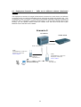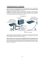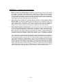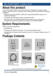
1
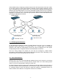
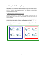
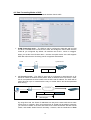
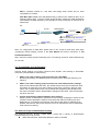
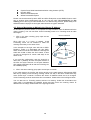
Unified Wired & Wireless Access System
Deployment Guide
Product Model: DWS-3000 Series, DWL-3500AP/8500AP
Version 2 .0
0
1
Table of Content
1. INTRODUCTION........................................................................................................................ 3
2. FLEXIBLE DEPLOYMENT........................................................................................................ 4
2.1 OVERLAY AND EDGE DEPLOYMENT ........................................................................................... 4
2.2 ADAPTABLE WIRELESS .............................................................................................................. 5
3. AP MANAGEMENT NETWORK AND CLIENT DATA NETWORK..................................... 7
3.1 AP MANAGEMENT NETWORK ................................................................................................... 8
3.2 CLIENT DATA NETWORK .......................................................................................................... 8
4. SETTINGS FOR FAST ROAMING GROUP............................................................................. 9
4.1
4.2
4.3
4.4
4.5
4.6
ROAMING GROUP AND VIRTUAL ACCESS POINT ........................................................................ 9
DATA FORWARDING MODES OF VAP ...................................................................................... 10
PREREQUISITES FOR FAST ROAMING ....................................................................................... 11
SELECT A PROPER AUTHENTICATION SETTING ......................................................................... 11
SELECT A MECHANISM TO MAINTAIN THE CLIENT’S IP ADDRESS ............................................. 12
ROAMING WITH NOTEBOOK .................................................................................................... 13
5. SEGREGATE TRAFFICS ON EACH VAP ............................................................................. 14
6. DEPLOYMENT SCENARIOS................................................................................................... 15
6.1
6.2
6.3
6.4
DEPLOYMENT SCENARIO 1 – VAPS ARE IN THE SAME SUBNET:................................................. 15
DEPLOYMENT SCENARIO 2 - VAPS ARE IN DIFFERENT SUBNETS:.............................................. 16
DEPLOYMENT SCENARIO 3 - VAPS ARE IN DIFFERENT SUBNETS (VLAN-BASED ROUTING): ........ 17
DEPLOYMENT SCENARIO 4 - L3 EDGE PEERS: ......................................................................... 18
APPENDIX A FREQUENT ASKED QUESTIONS: ................................................................... 19
2
1. Introduction
This document is to provide an overview of the variety of ways in which D-Link’s Unified
Wired & Wireless Access System can be deployed. It also details unique features on D-Link’s
Wireless Solution.
D-Link’s Unified Wired & Wireless Access System consists of Unified Switch and Access
Point (AP). There are 3 unique features that D-Link’s solution has which can be taken
advantage of:
1. This solution can be deployed either as an Overlay Device (also called a Wireless
Controller) or as an Edge Device that can leverage all the traditional wired
functionality built into this switch.
2. Adaptable Wireless – Wireless client traffic can either be routed back to Switch or
locally forwarded at the AP depending on the wireless application. This feature
provides unparalleled flexibility as well as enhanced security at the same time.
3. L3 Fast Roaming - even when the Access Points are in different IP subnets, the
clients can still roam seamlessly across the access points that are in the same
Roaming Domain. Up to 4 Peer Switches can be configured in a Roaming Domain,
which enables the roaming network to scale up to 192 APs and supports up to 2000
wireless clients simultaneously. This feature is mainly intended for Wireless VoIP
communication using Wi-Fi phones and other such devices which require the clients
to maintain their IP addresses even as they roam within the wireless domain.
This document is intended to provide a concept of deployment of D-Link’s Unified Access
System. For more information, please refer to ‘Unified Wired & Wireless Access System
Configuration Guide’ for configuration examples.
3
2. Flexible Deployment
2.1 Overlay and Edge Deployment
D-Link’s Unified Wired & Wireless Access System can act as either an Overlay device or an
Edge device, granting customers unprecedented flexibility when deploying D-Link’s Wireless
Solution.
1.
Unified Switch as Overlay device
SW3
SW2
SW1
Roaming group B
Roaming group A
In an Overlay solution, D-Link’s Unified Switch is deployed deep into the customer’s network
infrastructure. This approach enables the customer to have a mixed Wired & Wireless
network by embedding the Unified Switch into the customer’s existing network. Furthermore,
it also protects customer’s current investment because no other component in the
infrastructure needs to be replaced.
2.
Unified Switch as Edge device
SW3
Roaming group B
Roaming group A
In an Edge solution, D-Link’s Unified Switch is deployed at the edge. It enables customers to
fully utilize all its features by acting as both a wireless controller and an edge switch.
4
2.2 Adaptable Wireless
D-Link’s Adaptable Wireless is the driving technology behind Unified Access System’s
flexible deployment. There are 2 ways of implementing Adaptable Wireless: VLAN forwarding
(Non-Tunnel mode) and L3 Tunneling (Tunnel mode).
When under L3 Tunneling mode, the traffic from wireless clients will be tunneled back to
Unified Switch from AP.
Wireless data flow
L3 Tunneling mode
L2 or L3
Network
SSID1: Subnet 1
SSID2: Subnet 2
Unified Switch
Internet
SSID1: Subnet 1
SSID2: Subnet 2
When under VLAN forwarding mode, the traffic will not be tunneled back. Instead, it will be
VLAN tagged by AP and forwarded to uplink switch for processing.
Wireless data
flow
VLAN Forwarding
mode
L2 or L3
Network
Unified Switch
V10,
V20
V10,
V20
Internet
SSID1:
V10
SSID2:
SSID1:
V10
SSID2:
L3 Tunneling mode is an important feature of this D-Link’s solution. There are advantages for
enabling this feature:
1.
L3 Fast Roaming is achievable - the packets will be encapsulated by the AP or the
Unified Switch using DWAPP (D-Link Wireless AP Protocol) tunneling technology.
By utilizing this technology, wireless clients’ IPs will not change when roaming
across L3 network. Therefore clients can roam seamlessly across different networks.
2.
All the traffics from the clients will be forwarded back to the Unified Switch. By
having done this, you can utilize advanced features built in the Unified Switch to
manage the traffics, for example: ACL, QoS, and DHCP Server etc.
5
Comparison of VLAN Forwarding Mode and L3 Tunneling Mode
Description
VLAN Forwarding
All the wireless traffic will be VLAN
tagged by AP
L2 Roaming
L3 Roaming
Advantage
Yes
Yes
1. Easier configuration
2.
3.
Disadvantage
Saves more bandwidth and
provides better performance
because traffics are not
forwarded back to Unified
Switch.
Good for SSIDs designed for
staffs who will access network
resources around themselves
or for peer-to-peer Wi-Fi
phones
1. Traffics are not forwarded back
to Unified Switch hence some
advanced features on Unified
Switch like Port Mirroring, ACL,
Storm Control, DoS protection,
DHCP Server, DHCP Relay,
Bandwidth Control, etc, can not
be applied. However, those
features can be provided by
edge switch or other
devices/servers.
L3 Tunneling
All the wireless traffic will be forwarded
back to Unified Switch by AP using
DWAPP Tunnel technology.
Yes
Yes
1. Transparent to customer network, no
“VLAN explosion” problem
2. Better centralized policy for wireless
network - Traffics are forwarded back
to Unified Switch hence the advanced
features on Unified Switch like Port
Mirroring, ACL, Storm Control, DoS
protection, DHCP Server, DHCP
Relay, Bandwidth control, etc, can be
applied.
3. Good for SSIDs designed for Guest
Access because traffic is tunneled
back to the Wireless Switch for
centralized management
1. More complicated Unified Switch
configuration
2. Consume more bandwidth.
3. Need to care about performance particularly when AP and Unified
Switch are located at different sites.
Because client traffics will go back to
Unified Switch first.
2. When setting up a large wireless
network, configuring VLAN
throughout the network might be
an effort (VLAN explosion.)
Suggestion: It is suggested to consider implementing VLAN Forwarding mode first due to its
simplicity and better performance. You can consider L3 Tunneling when there is advanced
requirement for centralized policy management.
In the following 3 chapters a guideline for designing your wireless network will be introduced.
Simply follow the 3 steps then you will have a sketch of network layout. (If you do not have
requirement for ‘fast roaming’, step 2 can be ignored.)
1.
2.
3.
Design AP Management Network and Client Data Network.
Apply proper settings for fast roaming group.
Segregate Traffics of each Virtual AP on an AP
These 3 steps will be introduced in chapter 3, 4 and 5.
6
3. AP Management Network and Client Data Network
The D-Link Unified Access System utilizes the D-Link Wireless AP Protocol (DWAPP) for the
switch to discover, configure, manage, and monitor the APs. DWAPP is a CAPWAP-like
protocol that is used by wireless APs when sending traffic across L2 or L3 networks. DWAPP
is also used by Peer Switches to send information to each other.
Unified
Switch
(Peer Switch)
TCP/SSL
control packets
L2 or L3
Network
statistics
Unified Switch
UDP
For traffic between the Unified Switch and AP or among Peer Switches, DWAPP uses the
following transport protocols:
1) TCP Port 57777, SSL encryption for control packets such as firmware/profile
delivery, data, etc.
2) UDP Port 57775, 57776 for reports and statistics packets.
Therefore, if there are packet filtering devices between Unified Switch and APs or between
Peer Switches, be sure the following ports are opened on those devices bi-directionally:
UDP/57775
UDP/57776
TCP/57777
7
Unlike traditional way of deploying wireless network where AP and wireless clients are usually
on the same subnet, D-Link’s Unified Wired & Wireless Access System provides a secure
way for managing APs and wireless clients. This is achieved by separating AP Management
Network and Client Data Network. AP and its associated wireless clients are not necessarily
on the same subnet. This has a security benefit because Management and Data traffics are
separated. For example, ACL can be set up to prevent clients on Client Data Network from
accessing AP Management Network.
Unified Switch1
Profile
Firmware
10.1.1.1/24
Unified Switch2
L2 or L3
Network
10.1.1.2/24
172.16.1.1/24
10.2.2.2/24
Roaming group
Roaming group
192.168.2.x/24
192.168.1.x/24
3.1 AP Management Network
An AP Management Network consists of Unified Switches and APs. It is not necessary to
physically connect APs directly to a Unified Switch. For a Unified Switch to successfully
manage an AP, both the Unified Switch and the AP must be assigned an IP and proper
routing settings must be configured between the Unified Switch and the AP.
Once the routing settings are properly set, and APs are managed by Unified Switch
successfully, Unified Switch is able to push Profile and Firmware to APs. Monitoring of your
wireless network is also made possible at this moment.
3.2 Client Data Network
Wireless client can have IP subnet/VLAN that is different from the AP to which it is connecting.
As mentioned earlier, this has a security benefit. Another reason is for fast roaming where
client IP can not be changed while roaming to another AP.
By default, Wireless clients’ IP subnet will be identical to that of the AP they are connecting. If
you want to isolate a Client Data Network, you will need to enable VLAN forwarding mode or
L3 Tunneling mode on the AP. By doing so, clients can reside on a separated VLAN or IP
subnet. Please refer to Manual or Configuration Guide for more details.
8
4. Settings for Fast Roaming Group
‘Fast Roaming’ is a comprehensive feature provided by D-Link’s Unified Access System. It
means when a wireless client moves, disconnects with the original AP and connects to the
new AP that is closer to the client, the hand-over time is insignificant to the application
running on the client. This is particularly ideal for VoIP applications of which session
disconnection should be avoided.
4.1 Roaming Group and Virtual Access Point
A Roaming Group consists of a set of APs that are configured with the same SSID and
security settings. When a client roams, it connects to the same SSID thus maintains the
application sessions.
DWL-3500AP and DWL-8500AP support up to eight virtual access points (VAPs) on each
radio. This VAP feature allows you to segment each physical access point into eight logical
access points (per radio) that each supports a unique SSID and security policy.
The first step for designing the roaming network is to plan the roaming groups. By utilizing the
VAP feature, you can have multiple geographical overlapped roaming groups, as illustrated in
the following figure.
SSID:
Sales
SSID:
Sales
VoIP
VoIP
SSID:
Sales
SSID:
Sales
VoIP
VoIP
Sales Network
SSID:
R&D
SSID:
R&D
VoIP
VoIP
SSID:
R&D
SSID:
R&D
VoIP
VoIP
R&D Network
VoIP Network
9
4.2 Data Forwarding Modes of VAP
There are two modes by which the VAP forwards wireless clients’ traffic:
1. VLAN Forwarding mode – The SSID of VAP is configured to associate with a VLAN
ID. When a wireless client connects to the VAP, the AP tags the client's traffic with the
VLAN ID you configured. By default, all networks use VLAN 1, which is untagged.
When you set the VLAN ID other than 1, be sure the uplink device of the AP supports
IEEE 802.1Q so that the VLAN tag can be recognized and handled.
AP
Client
Uplink Device
Data
VLAN
Data
2. L3 Tunneling mode –The SSID of each VAP is configured to associate with an IP
subnet on which the wireless clients reside. When a wireless client connects to a VAP,
the AP encapsulates the client's traffic with the AP’s real IP address. The traffic will be
routed through Layer 3 networks all the way to Unified Switch and be decapsulated
after arriving.
Unified Switch
L3 Network
IP Packet
AP’s IP
Src IP
SW’s IP
IP Packet
Dst IP
Extra 20 bytes
By using this mode, the clients’ IP addresses can stay as the same while clients roam
across layer 3 networks. Since an extra 20-byte IP header will be added, previously
you need to be aware of the MTU size issue on the devices between AP and Unified
Switch, and enable Jumbo Frame if necessary. However, with the introduction of Path
10
MTU in firmware release 2.1, this issue has largely been solved and no extra
configuration is needed.
Path MTU (RFC 1191) is the standardized way to discover the maximum MTU of an
arbitrary Internet path. D-Link’s Unified Access System utilizes the ICMP Destination
Unreachable message defined by this standard to notify end points to shrink their IP
Packet size.
AP
Tunnel
1480 byte IP
Packet
1500 byte IP-IP
Packet
Unified Switch
Internet
1500 byte IP
packet
ICMP err msg: Only accept 1480 byte IP
Packet
1480 byte IP
Packet
Note: For configuration of Path MTU, please refer to the ‘Tunnel IP MTU Size’ field under
“Configuring Global Settings” section in the User Manual OR search ‘tunnel-mtu’ in CLI
Command Reference.
Note: These two modes (VLAN Forwarding and L3 Tunneling) cannot be used simultaneously
on one VAP.
4.3 Prerequisites for Fast Roaming
Through proper settings on D-Link’s Unified Access System, fast roaming is achievable.
There are 3 prerequisites for fast roaming:
1. VAPs in the same roaming group must have the same SSID.
By having this design, the clients feel like connecting to the same AP while they are
roaming.
2. VAPs in the same roaming group must have the same authentication settings.
After the AP authenticates the client, the Unified Switch stores and forwards the client
information to other APs in the same roaming group when necessary. When a client
roams, the re-authentication time is tiny because the neighboring APs already knew
the client information and the authentication settings are the same. Thus this shortens
the hand-over time.
3. Clients must keep the same IP address while roaming.
Keeping clients’ IP addresses is essential for fast roaming. Changing the client’s IP will
cause the client’s application sessions to be reset and make the roaming not ‘fast’.
Depending on your network environment, there are several ways to maintain the IP
address. Next section will provide a picture of how to maintain the client IP addresses
while clients are roaming.
4.4 Select a Proper Authentication Setting
For enhanced security, D-Link’s Unified Switch comes with a variety of authentication
mechanisms that you can choose:
MAC Authentication: adds MAC address to white or blacklist
11
Captive Portal: Web-based authentication using browser (HTTP)
Dynamic WEP
WPA Personal/Enterprise
WPA2 Personal/Enterprise
Please note that because Dynamic WEP and WPA Enterprise contact RADIUS server each
time a wireless client reassociates with an AP, they are NOT RECOMMENDED for fast
roaming, due to the long re-authentication time. For best security practice, please always use
WPA2 because it employs the strongest authentication encryption standard.
4.5 Select a Mechanism to Maintain the Client’s IP Address
As described in previous section, it is important to keep the same client IP address while the
client is roaming. You can use either VLAN Forwarding mode or L3 Tunneling mode to make
this happen.
Across L2 Network
1. APs in the same roaming group span across
layer 2 network
L2 Switch
Since APs are in a Layer 2 network, VLAN
Forwarding mode can be enabled to make the
roaming clients stay in the same VLAN.
VLAN 2
In the example on the right, each AP has an SSID:
Roaming. VLAN 2 is associated with this SSID.
When a client connects to this SSID, the AP tags the
traffic with VLAN 2. When the client roams, it does
not have to change its IP ‘cause it still stays in the
same VLAN.
If you use this configuration, and the VLAN ID is
other than 1 (default), be sure the uplink devices of
the APs and all the devices on the path between
APs support IEEE 802.1Q so that the VLAN tag can
be handled properly.
VLAN 2
SSID:
Roaming
SSID:
Roaming
Roaming group
VLAN 2
2. APs in the same roaming group span across layer 3 network
If the uplink devices of the APs and all the devices on the path between APs support IEEE
802.1Q, by utilizing VLAN Trunking, roaming clients can stay in the same VLAN while they
roam across layer 3 network. Therefore the client’s IP address needs not to be changed.
VLAN Forwarding mode is used under this circumstance. Please refer to the left figure below.
You can also use L3 Tunneling mode to achieve L3 roaming. Under this circumstance the
client traffic is encapsulated by DWAPP tunnel technique hence the roaming client’s IP
address will not change. Please refer to the right figure below.
12
Across L3 Network
Across L3 Network
L2/L3 Switch (802.1Q supported)
VLAN 2
L3 only Device
Unified Switch
VLAN 2
SSID:
Roaming
SSID:
Roaming
SSID:
Roaming
SSID:
Roaming
Roaming group
Roaming group
192.168.1.x/24
VLAN 2
More details will be revealed in Chapter 6.
4.6 Roaming with Notebook
Under most circumstances, fast roaming is not a must for data transferring such as Web, EMail or FTP traffics. When people carry a notebook walking through buildings, they do not
look at the screen and a short hand-over time is acceptable.
If you have requirement to demonstrate fast roaming with notebooks, please note that
Microsoft Windows clients are inherently slow in managing hand-offs - it allows AP signal
strength to become very low on connected AP before releasing client to next AP, even when
the next AP has greater signal strength.
To solve this inherent limitation of Microsoft Windows, wireless NIC vendors have
implemented fast roaming features to change the default behavior of Windows. Be sure you
choose the NIC card that supports following functions when demonstrating fast roaming with
notebook:
1) Fast Roaming (Intel calls it Roaming Aggressiveness), which dictates how “likely” the NIC
will switch to another AP with a stronger signal. If you want to stay "locked on" to a particular
AP, change the roaming aggressiveness setting to its lowest. When set to highest, your NIC
continuously tracks the link quality, and if any degradation occurs, it tries to find and roam to a
better AP.
2) When using WPA2 Enterprise, the NIC must support Key Caching. Although this feature
might not be found on the NIC datasheet, it’s a mandatory item for passing the Wi-Fi WPA2
test Therefore, if your NIC has Wi-Fi WPA2 Certification, it supports Key Caching.
13
5. Segregate Traffics on each VAP
Multiple VAPs (SSIDs) implemented on an AP usually have different security policies. For
example, a client connected to a ‘Guest’ SSID will stay in the guest network with limited
network access. On the other hand, a client connected to an ‘Employee’ SSID will have full
authorization to the network & Internet. You may want to segregate the traffics from each VAP
such that the clients on different VAP will not see each other and each has different security
policies. This then provides better security enforcement.
You can use VLAN Forwarding mode or L3 Tunneling mode - Each VAP is associated with
different VLAN ID or different IP subnet. By doing this, clients on different VAPs are on
different VLAN or IP Subnet. Further more, you can set up ACL on your network devices to
limit the network resource each VLAN/IP subnet can access.
14
6. Deployment Scenarios
Given below are some of the typical deployments, and each provides fast roaming.
6.1 Deployment Scenario 1 – VAPs are in the same subnet:
This deployment may consist of a single or multiple Unified Switches at the edge connected
together in the same VLAN (subnet), and the APs are either directly connected or connected
over switches. In other words, there are no subnet boundaries to cross between the APs and
between the APs and Unified Switches. This configuration does not require L3 Tunneling to
accomplish seamless roaming. Each “service” (or VAP) is separated by VLANs and can have
different security configurations.
In this configuration, the “network” management interface address can be used as the only IP
address on the switch and is used as the WLAN component IP address. Therefore static
address can be used on the APs on the same subnet as the “network” IP. If DHCP is used,
ensure that the APs have a route to the network IP address of the Unified Switch.
Scenario 1
Unified Switch
10.90.90.90/8
SSID:
Guest Network
SSID:
Guest Network
AP1 10.90.90.91/8
AP2 10.90.90.92/8
Seamless Roaming
CL1
15
6.2 Deployment Scenario 2 - VAPs are in different subnets:
This deployment consists of a single Unified Switch and APs connected through a L3 device
(router). Under normal circumstances, VLAN Forwarding mode can do L3 Roaming.
However, since the L3 device (router) does not support 802.1Q or VLAN Routing, L3
Tunneling is required in this configuration to achieve seamless roaming across APs.
Services that require fast L3 roaming will need to be configured as L3 Tunneled VAPs to
allow subnet roaming. There is no need for Jumbo Frame under Tunnel Mode because of
Path MTU. Services that do not require fast roaming across L3 boundaries can be
configured to non-Tunnel Mode.
Scenario 2
L3 Device
Unified Switch
L3 Tunnel interface (for Voice)
10.30.254.254/16
SSID:
Employee: VLAN 1 (not for roaming)
Voice: 10.30.x.x /16 (L3 tunneling)
SSID:
Employee: VLAN 1 (not for roaming)
Voice: 10.30.x.x /16 (L3 tunneling)
AP1 192.168.20.x
AP2 192.168.30.x
Seamless Roaming
16
6.3 Deployment Scenario 3 routing):
VAPs are in different subnets (vlan-based
This deployment consists of a single Unified switch connected to a L2/3 device, and APs are
connected to the core with VLAN-based routing (ensure that VLANs are properly set). This
configuration does not require L3 Tunneling to accomplish seamless roaming if the 802.1Q
VLAN has been configured in customer’s environment. In other words, through using VLAN
Routing, you can spread VLANs across the network such that each VLAN has a path
between each of the APs in the network.
Scenario 3
L2/3 Device
VLAN 7/20/100/200
Unified Switch
VLAN 7/30/100/200
SSID:
Guest Network: VLAN 100
Employee: VLAN 200
Voice: VLAN 7
AP1 VLAN 20
192.168.20.x
SSID:
Guest Network: VLAN 100
Employee: VLAN 200
Voice: VLAN 7
AP2 VLAN 30
192.168.30.x
Seamless Roaming
17
6.4 Deployment Scenario 4 - L3 Edge Peers:
This deployment consists of multiple Unified Switches connected to a L3 core. APs are either
directly connected to the Unified Switch or over a L2 or L3 device. This configuration does
require L3 Tunneling to accomplish seamless roaming because APs belonged to the same
roaming group are connected through a L3 only device.
Normally, when Tunneling is used, an extra 20 bytes are added in the headers for
encapsulation, which causes the packet to have a length of 1520 bytes. However, since Path
MTU will set the packet size to 1480 bytes, which comes to 1500 bytes after the extra header,
L3 Tunneling is achievable without enabling Jumbo Frame.
Scenario 4
Unified Switch2
Across L3 Network
L3 Device
Unified Switch1
172.17.6.0/24
Network IP: 10.90.90.90
Loopback: 192.168.10.254
L3 Tunnel: 192.168.250.254
Network IP: 172.17.7.254
Loopback: 192.168.15.254
L3 Tunnel: 192.168.250.253
AP2
172.17.7.x
172.17.5.0/24
Radius Server
10.90.90.100
AP1
192.168.20.x
FTP Server
Audio/Video Server
192.168.250.x
Seamless Roaming
CL1
SSID:
L3-Tunnel: 192.168.250.x
In this scenario, the clients are assigned in the IP subnet: 192.168.250.0/24. Both Unified
Switch1 and Unified Switch2 must have a corresponding tunnel interface (192.168.250.254
and 192.168.250.253) to communicate with the clients.
When a client first connects to AP1, AP1 will encapsulate the client’s traffic and send it to the
loopback interface (or L3 Tunneling interface if loopback interface is not configured) of Unified
Switch1 (192.168.10.254). It is important to know that when this client roams and connects to
AP2, the client’s IP will not be changed, and AP2 will encapsulate and send the client’s traffic
back to the loopback interface of Unified Switch1 (192.168.10.254) and not that of Unified
Switch 2 (192.168.15.254)
18
APPENDIX A Frequent Asked Questions:
1.
Where to place the Unified Switch & AP? The Access Points need not be directly
connected to the Switch to be managed by it; besides, the wireless switches need not
be directly connected to each other to form a peer network. However, it is necessary
that all the Switches and the Access Points are a part of the same Local Area Network.
In other words, the Wireless Switch cannot manage APs located across a Public Wide
Area Network (internet), especially across a NAT device.
2.
What should be configured if a packet filtering device is used between Unified
Switch & AP? The device must allow frames with either source or destination port set to
one of these values: UDP/57775, UDP/57776, TCP/57777.The ports may appear as
either destination port or source port, in either case the frame must be allowed. In
addition, IP-IP tunnel (IP protocol 4) needs to be enabled as well on the Firewall.
3.
About WPA2 Enterprise Authentication: The solution also supports authenticated fast
roaming using WPA2 Enterprise authentication in addition to other mechanisms. But,
this is not currently supported by most of the wireless voice clients which only support
WEP. Moreover, the newer versions of Windows XP Clients do support WPA2 but
demonstrating L3 Fast Roaming with Windows Clients is not recommended to highlight
seamless roaming as Windows Clients are inherently slow in managing hand-offs.
The Configuration Guide indicates demonstrating roaming between the APs by powering
down one of the APs thus forcing the clients to “roam” to the second AP. However, it
must be noted that this is really a “fail-over” and not really roaming. In particular, when
using WPA2 Enterprise for authentication, when an AP is powered down and brought
back again, it loses the dynamic key information previously received from the switch
causing the client who roams to that switch to re-authenticate itself from the Radius
server. Although, none of these induced delays are more than a few milli-seconds and
users would only see the loss of one ping, it must be pointed out that in real roaming
under these delays would not exist. In the lab testing, we have recorded clients roaming
with a hand-off time of 23 milli-seconds which is too quick to be noticed by a user.
19