1
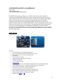
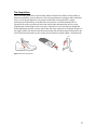
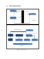
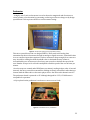
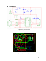
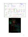
EEL 4924C Electrical Engineering Design (Senior Design) Final Design Report April 21st 2009 Name: Muqeet S. Mujahid Email: [email protected] Phone: (904) 208‐1515 ABSTRACT Team Name: The Beatkicks Team Members: Name: Miguel D. Cepeda Email: [email protected] Phone: (954) 309‐7714 The idea for the 3PM (resembling BPM, also MP3 spelled backwards) arose after the 3PM design team, both avid runners, realized that music listened to while running or jogging greatly affects the rhythm or pace of each session. It has thus been our effort to design a product that will use this quality of music as an advantage while running. Our project consisted of designing a pedometer to be worn by the user on his/her belt. Using this pedometer, a pace in beats per minute is calculated by counting running total of steps taken in ten second interval windows. Our designed music device interprets this information and picks a song closest in tempo to the speed of the user. Our sensor includes an accelerometer that produces a change in voltage caused by a change in acceleration when the user places a step. This information is passed to an ATMEL micro‐controller. The micro‐controller calculates the pace of the user. This information is then transmitted wirelessly by using a set of XBee radios. On the receiver side an mp3 decoder slaving off of an ATMEL micro‐controller receives this information and selects a tune. 1 Table of Contents 3 List of Table & Figures 4 Technical Objective 5 III. Concept / Technology 7 IV. Project Architecture 11 Division of Labor 16 User Manual 17 Bill of Material 17 VIII. Gantt Chart 18 IX. Appendices 19 I. II. V. VI. VII. Project Introduction 2 I. INTRODUCTION The 3PM project was designed for users who love to jog/run while listening to music for entertainment while exercising. The product consists of a sensor which is attached to the user’s belt and an MP3 player which can either be worn or kept nearby for stationary running indoors. When worn, the sensor reads the user’s pace to select a song on the MP3 player that will match their pace in beats per minute (BPM). This is practical for runners to either consistently maintain a certain pace during their workouts or for runners who wish to increase their running speed. This device provides a great way to motivate runners to know their rhythm and test their limits, all while enjoying their favorite music! A commercial product which closely resembles our product is Apple’s Nike + Ipod. The Nike + Ipod device uses a pedometer that wirelessly transmits rhythm/pace information read from a runner’s shoe such as distance traveled, mph, time spent running, etc. It does not, however, have a feature that selects a song based on the user’s pace as our device ensures. In our design we have also minimized our costs by using the least amount of parts to achieve our proposed functionality. 3 List of Tables & Figures Table 1: Division of Labor 17 Table 2: Bill of Material 18 III. Figure 1: ATMEGA 324P TQFP 7 IV. Figure 2: Nike+iPod Competition 10 V. Figure 3: Project Architecture Diagram 11 I. II. VI. Figure 4: Oscilliscope reading from accelerometer testing 12 Figure 5: Final PCB for Sensor / Pedometer 12 Figure 6: Final PCB for Music Player 13 Figure 7: Software Realization 15 Figure 8: Gantt Chart 18 XI. Figure 9: Sensor / Pedometer Schematic 19 XII. Figure 10: Sensor / Pedometer PCB Layout 19 XIII. Figure 11: Music Player Device Schematic 20 XIV. Figure 12: Music Player Device PCB Layout 20 VII. VIII. IX. X. 4 II. TECHNICAL OBJECTIVES The project was designed to operate at different voltage levels. For the pedometer a 3V battery pack was used to power all of its components including the micro‐controller, whose operational voltage range is between 1.8V – 5.5V. The music player uses a 5V battery back to be powered with its LCD powered on 5V and a voltage regulator to step down the board’s voltage to 3.3V, in order to operate its other components. Main Objective The main objective of this project was to design a sensor and a music device such that both modules can communicate wirelessly to pick up a song closest in tempo to the speed of the user. Our 3PM consists of only the two aforementioned parts: the belt sensor/pedometer and the music device. Features Belt Sensor/Pedometer 3axis Accelerometer: A single y‐axis is used on the accelerometer to detect the magnitude and direction as a vector quantity of acceleration by generating or altering a reference voltage set by design specifications. ATMEL Atmega324P: This micro‐controller used in our design project reads in the analog data transmitted by the accelerometer through its analog‐to‐digital converter. A threshold value is set to compare input values against in order to measure a sharp enough jolt to count as a step. XBee Series 1 Radio: Once the steps are counted and a BPM (beats per minute) reading is taken, after 10 second intervals, the micro‐controller transmits the reading wirelessly via an XBee radio sharing a channel with the XBee radio on the music player device. 3V Battery Pack: The pedometer board is powered on 3V. Although designed for 3.3V, 0.3V difference is acceptable for operation. Belt Clip: A clip is placed on the pedometer’s enclosure to secure to user’s belt. Music Player Device µMP3 Module: This module is programmed and interfaced with the ATMEL Atmega 324P (music player side) to control such functions as playing, pausing, stopping, volume control, etc. The Atmega 324P allows us to include push buttons to control these features on the user side. ATMEL Atmega 324P: To ensure proper communication between the two devices the music player device also used an Atmega 324P micro‐controller to interface between the µMP3 module, its respective push buttons, the LCD screen and the XBee radio. 5 XBee Series 1 Radio: The Atmega 324P receives the BPM readings from the pedometer, which are being updated every 10 seconds, through the XBee radio on the music player side. LCD Screen: The LCD screen provides a user interface that allows the user to view functionalities and actions operated by the music player device such as which song in the player’s playlist is being played and what the current pace is in BPM. 6 III. CONCEPT/TECHNOLOGY ATMEL Atmega 324P Figure 1: ATMEGA 324P TQFP Features • High‐performance, Low‐power AVR® 8‐bit Microcontroller • High Endurance Non‐volatile Memory segments – 16/32/64K Bytes of In‐System Self‐programmable Flash program memory – 512B/1K/2K Bytes EEPROM – 1/2/4K Bytes Internal SRAM – Write/Erase Cycles: 10,000 Flash/ 100,000 EEPROM – Data retention: 20 years at 85°C/100 years at 25°C(1) – Optional Boot Code Section with Independent Lock Bits In‐System Programming by On‐chip Boot Program True Read‐While‐Write Operation – Programming Lock for Software Security • Peripheral Features – Two 8‐bit Timer/Counters with Separate Prescalers and Compare Modes – One 16‐bit Timer/Counter with Separate Prescaler, Compare Mode, and Capture Mode – Real Time Counter with Separate Oscillator – Six PWM Channels – 8‐channel, 10‐bit ADC Differential mode with selectable gain at 1x, 10x or 200x – Byte‐oriented Two‐wire Serial Interface – Two Programmable Serial USART – Master/Slave SPI Serial Interface – Programmable Watchdog Timer with Separate On‐chip Oscillator – On‐chip Analog Comparator – Interrupt and Wake‐up on Pin Change • I/O and Packages – 32 Programmable I/O Lines – 40‐pin PDIP, 44‐lead TQFP, 44‐pad VQFN/QFN/MLF (ATmega164P/324P/644P) – 44‐pad DRQFN (ATmega164P) – 49‐ball VFBGA (ATmega164P/324P) • Operating Voltages – 1.8 ‐ 5.5V for ATmega164P/324P/644PV – 2.7 ‐ 5.5V for ATmega164P/324P/644P • Speed Grades – ATmega164P/324P/644PV: 0 ‐ 4MHz @ 1.8 ‐ 5.5V, 0 ‐ 10MHz @ 2.7 ‐ 5.5V 7 – ATmega164P/324P/644P: 0 ‐ 10MHz @ 2.7 ‐ 5.5V, 0 ‐ 20MHz @ 4.5 ‐ 5.5V • Power Consumption at 1 MHz, 1.8V, 25°C for ATmega164P/324P/644P – Active: 0.4 mA – Power‐down Mode: 0.1μA – Power‐save Mode: 0.6μA (Including 32 kHz RTC) The ATMEL chips used in our design were chosen mainly because of the fact that it contained two UART/USARTs which was necessary on the music player device board in order to transmit and receive data serially between the XBee Series 1 Radio and the µMP3 module. The same chip was also used on the sensor/pedometer board to facilitate communication between boards. Originally an ATMEL Atmega 32A was used for the pedometer (which only needs a single UART/USART for the interfacing between the Atmega and the accelerometer), but we soon realized we were dealing with serial communication errors due to the incompatibility of using different ATMEL chips. The 16‐bit counter featured in the Atmega 324P chip was useful in setting a time divisor in seconds to calculate the number of steps taken by the user over time, generating a BPM value to be processed by the music player device. µMP3 Module FEATURES Plays MP3, PCM WAV, and IMA ADPCM WAV files Easy to use SD card interface (works with MMC cards as well) MP3 playback control via serial or parallel interface Pitch control Play tones (no files needed) Simple serial control interface (non‐inverted) 2400 bps to 115200 bps 3 to 5 volt operating range RoHS Compliant Low power operation ‐ less than 60mA @ 5V during playback ‐ less than 30mA @ 5V idle Small module footprint (2.5" x 2"/6.35cm x 5.08cm) with 4x40 mounting holes FAT16 and FAT32 compatible ‐ 32MB to 2GB and beyond Read and write data files as well as audio playback Easily interfaced with any microcontroller (PIC, AVR, 8051, etc.) Supports MMC (Multi‐Media Card) and SD (Secure Digital) cards Chipset available (TQFP44 + LQFP48) RoHS compliant. Module images: Front and Back 8 We used this MP3 module due to its ease of use, serial control interface and its support of MMC (Mulit‐Media Card) and SD (Secure Digital) Cards to allow for memory that is as large as the user sees fit. A big role in its selection was also its NTFS file system compatibility. This makes it unnecessary to convert song files into anything other than its native format. The MP3 player’s operating range was also convenient for our design since it is from 3 to 5 volts, capable of operating on either 3.3V or 5V. In addition to this the µMP3 module proved to be easy to interface using ATMEL chips as its feature description indicates. ADXL322 3‐axis Accelerometer Although our design specifications did not require 3 axes on our accelerometer we used the ADXL322 breakout board due to its diminutive size and its few number of pins. Also the devices power operating range was between 2.4V and 5.25V which was within our powering constraints. XBee Series 1 Radios Xbee Series 1 Radios were used in our project due to their ease of use in serial communication between these and the ATMEL chips as well as their ease of use in programming in order to communicate with one another. The range we needed wasn’t any more than up to 300ft, their range according to their specifications, and their 250 kbps RF data rate for fast transmission between radios. The XBees also followed IEEE 802.15.4 networking protocol, suitable for reliable data communication. 9 The Competition There are many pedometers in the market, which calculate the number of steps taken, or distance traveled by a person. However few of these pedometers integrate music with their device. Even though Apple Inc. has partnered with Nike to bring the Nike + Apple pedometer into the market, we would like to incorporate a new functionality into its operation. We wish to provide the user with a device that automatically selects a song matching the closest tempo to his or her pace. Therefore, we not only want to design and build a pedometer but also a music device that will select a play list according to the pace of the jogger/walker. We believe that this functionality will provide instant motivation for the user to interactively listen to music as they exercise. Below is Apple’s Nike + iPod Sport Kit: Figure 2: Nike+iPod Competition 10 IV. PROJECT ARCHITECTURE Accelerometer M E A/D Xbee (Serial Out) G Pace of user A Power (3.3V) 3 2 Shoe Sensor 4 RX/TX (PICK A SONG) Xbee (Serial In) RX/TX (Pace of user) MEGA32 - A VS1002 (Encoder) MEGA – 324P SD CARD Audio out Input (Buttons) Output (LCD) Power to all components (3.3V) LCD needs 5V Music Player Figure 3: Project Architecture Diagram 11 Pedometer A single y‐axis 2‐axis accelerometer is used to detect the magnitude and direction as a vector quantity of acceleration by generating or altering a reference voltage set by design specifications. Below picture shows our accelerometer testing: Figure 4: Oscilliscope reading from accelerometer testing This micro‐controller used in our design ATMEGA ‐324P reads in the analog data transmitted by the accelerometer through its analog‐to‐digital converter. A threshold value is set to compare input values against in order to measure a sharp enough jolt to count as a step. Any time a reading less than threshold value is calculated the step counter is incremented by one. An interrupt is fired every ten seconds to calculate the speed of the user. Number of steps in 10 seconds is multiplied to find the speed of the user in beats per minute. Once the steps are counted and a BPM (beats per minute) reading is taken, after 10 second intervals, the micro‐controller transmits the reading wirelessly via an XBee radio sharing a channel with the XBee radio on the music player device. Our Xbee radio channel was #11. The pedometer board is powered on 3V. Although designed for 3.3V, 0.3V difference is acceptable for operation. A clip is placed on the pedometer’s enclosure to secure to user’s belt. Figure 5: Final PCB for Sensor / Pedometer 12 Music Player This ump3 module is programmed and interfaced with the ATMEL ATMEGA 324P to control such functions as playing, pausing, stopping, volume control, etc. These functions are carried out by having pushbuttons interfaced with MEGA‐324P. This micro‐controller has algorithms to pick out song according to user’s pace. The ATMEGA 324P receives the BPM readings from the pedometer, which are being updated every 10 seconds, through the XBee radio on the music player side. The LCD screen provides a user interface that allows the user to view functionalities and actions operated by the music player device such as which song in the player’s playlist is being played and what the current pace is in BPM. The music player is power by a 5‐volt battery supply. Figure 6: Final PCB for Music Player 13 Flowchart & Diagrams Software Realization Start Step Counter M i Pedometer Yes Accel< 325 Step Counted Counter + 1 No Step Not Counted No 10 secs up? Yes Reset Step Counter and Compute BPM No Read Pressed? Transmit BPM read from sensor to MP3 Yes MP3 Player PLAY Use BPM to find song on MP3 player 14 Play Loop PLAY Is song over? Yes No Do Nothing Read Pressed? No STOP Yes Use BPM to find song on MP3 player Figure7: Software Realization 15 V. DIVISION OF LABOR Task Preliminary Research: Sensor Testing MP3 Device Output Characteristics of Accelerometer MP3 Encoder / ATMEL Integration Ordering Parts: Sensor Components MP3 Components Design Overview / Layout: Sensor Breadboarding MP3 Breadboarding Sensor PCB MP3 PCB Coding: Sensor Code MP3 Code Debugging: Sensor Code MP3 Code Demonstrations Team Member MM, MC MM, MC MC MM MC MM MM, MC MM MM, MC MM, MC MM, MC MM MM, MC MM, MC MM, MC Table 1: Division of Labor 16 VI. USER MANUAL Step 1: Clip sensor / pedometer to belt and begin running at desired pace. Step 2: When target pace or running rhythm is reached push button #1 to take BPM reading. Step 3: Select Play (button # 2) to play song that matches your running pace Step 4: If at any point in time you wish to select song to match a different running pace press Stop (button #3 ) and start again from Step 2, otherwise continue running at current pace to allow for MP3 player to automatically select songs from playlist to match current pace Other Features: LCD displays BPM reading taken (after pressing button #1) as well as song info and BPM associated with song Buttons #4 and #5 control volume of MP3 player VII. BILL OF MATERIAL Part / Component Amount MEGA‐324P ‐ TQFP 2 XBee Series 1 2 Accelerometer 1 LCD 1 µMP3 Module 1 Battery Pack (Pedometer) 1 Battery Pack (Music Player) 1 PCB (Music Player) 1 Total Cost Price Per Unit $6.00 $24.00 $20.00 $8.00 $143.16 $2.00 $10.00 $33.00 Total $12.00 $48.00 $20.00 $8.00 $143.16 $2.00 $10.00 $33.00 $276.16 Table 2: Bill of Material 17 VIII. GANTT CHART Figure 8. Gantt Chart 18 IX. APPENDICES Figure 9. Sensor / Pedometer Schematic Figure 10. Sensor / Pedometer PCB Layout 19 Figure 11. Music Player Device Schematic Figure 12. Music Player Device PCB Layout 20 #include <avr/io.h> #include <util/delay.h> #include "LCD.h" #include "commands.h" #include <string.h> #include <stdlib.h> #include <stdio.h> int main(void) { LCD_INIT(); serial(); //Serial Comms. for Shoepod serial1(); //Serial Comms. for mp3 mod. DDRC = 0b00000000; //Set up Data Direction Registor for PORTC buttons char string0[20]; //String 0 is used to put the received value of steps //char string1[30]; int bpm_read; //This variable hold the converted integer BPM value char reading[20]; //This print BPM reading int volcount = 6; vol50(); start: while(1) { if((PINC & 0b00000001) == 0b00000001 ) { _delay_ms(50); LCD_COMMAND(LCD_CLEAR_HOME); LCD_STRING("Reading...."); 21 ReadLineUSART0(string0); //Read the BPM from the USART over XBee ReadLineUSART0(string0); ReadLineUSART0(string0); ReadLineUSART0(string0); bpm_read = atoi(string0); //Convert Char string to an integer sprintf(reading, "BPM = %i", bpm_read); LCD_ADDR(0x40); LCD_STRING(reading); _delay_ms(100); if(bpm_read >= 110 && bpm_read < 115) { Play110(); if(bpm_read >= 115 && bpm_read < 120) { Play115(); } if(bpm_read >= 120 && bpm_read < 125) { Play120(); } if(bpm_read >= 125 && bpm_read < 130) { Play125(); } if(bpm_read >=130 && bpm_read < 135) { Play130(); goto start; } goto start; goto start; goto start; goto start; 22 } if(bpm_read >= 135 && bpm_read < 140) { Play135(); } if(bpm_read >= 140 && bpm_read < 145) { Play140(); } if(bpm_read >= 145 && bpm_read < 150) { Play145(); } if(bpm_read >= 150 && bpm_read < 155) { Play150(); } if(bpm_read >= 155 && bpm_read < 160) { Play155(); } if(bpm_read >= 160 && bpm_read < 165) { Play160(); } goto start; goto start; goto start; goto start; goto start; goto start; 23 if(bpm_read >= 165 && bpm_read < 170) { Play165(); } if(bpm_read >= 170 && bpm_read < 175) { Play175(); } else { stop(); } if((PINC & 0b00000010) == 0b00000010) { _delay_ms(50); LCD_COMMAND(LCD_CLEAR_HOME); LCD_STRING("Play/Pause"); _delay_ms(100); goto start; goto start; } Play170(); } if((PINC & 0b00000100) == 0b00000100) { _delay_ms(50); LCD_COMMAND(LCD_CLEAR_HOME); LCD_STRING("Stop"); _delay_ms(100); stop(); 24 } if((PINC & 0b00001000) == 0b00001000 && volcount == 14) { _delay_ms(65); LCD_COMMAND(LCD_CLEAR_HOME); LCD_STRING("Volume Up"); _delay_ms(100); vol130(); volcount‐‐; LCD_COMMAND(LCD_CLEAR_HOME); if((PINC & 0b00001000) == 0b00001000 && volcount == 13) { _delay_ms(65); LCD_COMMAND(LCD_CLEAR_HOME); LCD_STRING("Volume Up"); _delay_ms(100); vol120(); volcount‐‐; LCD_COMMAND(LCD_CLEAR_HOME); if((PINC & 0b00001000) == 0b00001000 && volcount == 12) { _delay_ms(65); LCD_COMMAND(LCD_CLEAR_HOME); LCD_STRING("Volume Up"); _delay_ms(100); ///// } } 25 vol110(); volcount‐‐; LCD_COMMAND(LCD_CLEAR_HOME); if((PINC & 0b00001000) == 0b00001000 && volcount == 11) { _delay_ms(65); LCD_COMMAND(LCD_CLEAR_HOME); LCD_STRING("Volume Up"); _delay_ms(100); vol100(); volcount‐‐; LCD_COMMAND(LCD_CLEAR_HOME); ; } } if((PINC & 0b00001000) == 0b00001000 && volcount == 10) { _delay_ms(65); LCD_COMMAND(LCD_CLEAR_HOME); LCD_STRING("Volume Up"); _delay_ms(100); vol90(); volcount‐‐; LCD_COMMAND(LCD_CLEAR_HOME); if((PINC & 0b00001000) == 0b00001000 && volcount == 9) { LCD_COMMAND(LCD_CLEAR_HOME); LCD_STRING("Volume Up"); _delay_ms(100); vol80(); volcount‐‐; LCD_COMMAND(LCD_CLEAR_HOME); } _delay_ms(65); 26 } if((PINC & 0b00001000) == 0b00001000 && volcount == 8) { _delay_ms(65); LCD_COMMAND(LCD_CLEAR_HOME); LCD_STRING("Volume Up"); _delay_ms(100); vol70(); volcount‐‐; LCD_COMMAND(LCD_CLEAR_HOME); if((PINC & 0b00001000) == 0b00001000 && volcount == 7) { _delay_ms(65); LCD_COMMAND(LCD_CLEAR_HOME); LCD_STRING("Volume Up"); _delay_ms(100); vol60(); volcount‐‐; LCD_COMMAND(LCD_CLEAR_HOME); } if((PINC & 0b00001000) == 0b00001000 && volcount == 6) { LCD_COMMAND(LCD_CLEAR_HOME); LCD_STRING("Volume Up"); _delay_ms(100); vol50(); volcount‐‐; LCD_COMMAND(LCD_CLEAR_HOME); } if((PINC & 0b00001000) == 0b00001000 && volcount == 5) { } _delay_ms(65); 27 _delay_ms(65); LCD_COMMAND(LCD_CLEAR_HOME); LCD_STRING("Volume Up"); _delay_ms(100); vol40(); volcount‐‐; LCD_COMMAND(LCD_CLEAR_HOME); } if((PINC & 0b00001000) == 0b00001000 && volcount == 4) { _delay_ms(65); LCD_COMMAND(LCD_CLEAR_HOME); LCD_STRING("Volume Up"); _delay_ms(100); vol30(); volcount‐‐; LCD_COMMAND(LCD_CLEAR_HOME); } if((PINC & 0b00001000) == 0b00001000 && volcount == 3) { _delay_ms(65); LCD_COMMAND(LCD_CLEAR_HOME); LCD_STRING("Volume Up"); _delay_ms(100); vol20(); volcount‐‐; LCD_COMMAND(LCD_CLEAR_HOME); } if((PINC & 0b00001000) == 0b00001000 && volcount == 2) { _delay_ms(65); LCD_COMMAND(LCD_CLEAR_HOME); LCD_STRING("Volume Up"); _delay_ms(100); vol10(); 28 volcount‐‐; LCD_COMMAND(LCD_CLEAR_HOME); } if((PINC & 0b00001000) == 0b00001000 && volcount == 1) { _delay_ms(65); LCD_COMMAND(LCD_CLEAR_HOME); LCD_STRING("Volume Up"); _delay_ms(100); vol0(); volcount++; LCD_COMMAND(LCD_CLEAR_HOME); } //***************************8** if((PINC & 0b00010000) == 0b00010000 && volcount == 2) { _delay_ms(65); LCD_COMMAND(LCD_CLEAR_HOME); LCD_STRING("Volume Down"); _delay_ms(100); vol10(); volcount++; LCD_COMMAND(LCD_CLEAR_HOME); if((PINC & 0b00010000) == 0b00010000 && volcount == 3) { _delay_ms(65); LCD_COMMAND(LCD_CLEAR_HOME); LCD_STRING("Volume Down"); _delay_ms(100); } vol20(); 29 volcount++; LCD_COMMAND(LCD_CLEAR_HOME); if((PINC & 0b00010000) == 0b00010000 && volcount == 4) { _delay_ms(65); LCD_COMMAND(LCD_CLEAR_HOME); LCD_STRING("Volume Down"); _delay_ms(100); vol30(); volcount++; LCD_COMMAND(LCD_CLEAR_HOME); if((PINC & 0b00010000) == 0b00010000 && volcount == 5) { _delay_ms(65); LCD_COMMAND(LCD_CLEAR_HOME); LCD_STRING("Volume Down"); _delay_ms(100); vol40(); volcount++; LCD_COMMAND(LCD_CLEAR_HOME); if((PINC & 0b00010000) == 0b00010000 && volcount == 6) { LCD_COMMAND(LCD_CLEAR_HOME); LCD_STRING("Volume Down"); _delay_ms(100); vol50(); volcount++; LCD_COMMAND(LCD_CLEAR_HOME); if((PINC & 0b00010000) == 0b00010000 && volcount == 7) } } } _delay_ms(65); } 30 { _delay_ms(65); LCD_COMMAND(LCD_CLEAR_HOME); LCD_STRING("Volume Down"); _delay_ms(100); vol60(); volcount++; LCD_COMMAND(LCD_CLEAR_HOME); if((PINC & 0b00010000) == 0b00010000 && volcount == 8) { _delay_ms(65); LCD_COMMAND(LCD_CLEAR_HOME); LCD_STRING("Volume Down"); _delay_ms(100); vol70(); volcount++; LCD_COMMAND(LCD_CLEAR_HOME); if((PINC & 0b00010000) == 0b00010000 && volcount == 9) { _delay_ms(65); LCD_COMMAND(LCD_CLEAR_HOME); LCD_STRING("Volume Down"); _delay_ms(100); vol80(); volcount++; LCD_COMMAND(LCD_CLEAR_HOME); if((PINC & 0b00010000) == 0b00010000 && volcount == 10) { _delay_ms(65); LCD_COMMAND(LCD_CLEAR_HOME); LCD_STRING("Volume Down"); _delay_ms(100); } } } 31 vol90(); volcount++; LCD_COMMAND(LCD_CLEAR_HOME); if((PINC & 0b00010000) == 0b00010000 && volcount == 11) { _delay_ms(65); LCD_COMMAND(LCD_CLEAR_HOME); LCD_STRING("Volume Down"); _delay_ms(100); vol100(); volcount++; LCD_COMMAND(LCD_CLEAR_HOME); if((PINC & 0b00010000) == 0b00010000 && volcount == 12) { _delay_ms(65); LCD_COMMAND(LCD_CLEAR_HOME); LCD_STRING("Volume Down"); _delay_ms(100); vol110(); volcount++; LCD_COMMAND(LCD_CLEAR_HOME); if((PINC & 0b00010000) == 0b00010000 && volcount == 13) { _delay_ms(65); LCD_COMMAND(LCD_CLEAR_HOME); LCD_STRING("Volume Down"); _delay_ms(100); vol120(); volcount++; LCD_COMMAND(LCD_CLEAR_HOME); } } } } 32 if((PINC & 0b00010000) == 0b00010000 && volcount == 14) { _delay_ms(65); LCD_COMMAND(LCD_CLEAR_HOME); LCD_STRING("Volume Down"); _delay_ms(100); vol130(); LCD_COMMAND(LCD_CLEAR_HOME); } } } 33 #include <avr/io.h> #include <util/delay.h> #include "LCD.h" #include <string.h> #include <stdlib.h> #include <stdio.h> #include <avr/interrupt.h> volatile int inter_count = 0; volatile int bpm = 0; volatile int i = 0; char bpm_string[20]; int count; char test[20]; void serial(void) { UCSR0A = 0b00100010; //RXC|TXC|UDRE|Fe|DOR|UPE|U2X|MPCM UCSR0B = 0b00011000; //RXCIE|TXCIE|UDRIE|RXEN|TXEN|UCSZ2|RXB8|TXB8 UCSR0C = 0b00000110; //UMSEL1|UMSEL|UPM|USBS|UCSZ1|UCSZ0|UCPOL UBRR0 = 103; //Baud Rate set to 9600bps DDRD = 0b00000010; //Date Direction Register for Port D } void transmit(char data) { while(!(UCSR0A & (1<<UDRE0))); //Checking Flag to make sure it is empty on Bit 5 to transmit UDR0 = data; //Write data to UDR1 ‐ USART I/O Data Register } char receive(void) { while(!(UCSR0A & (1<<RXC0))); //Wait for data to be received 34 return UDR0; //Return UDR whenever called from 'main' } void ReadLineUSART(char *string) { int k=0; char byte; byte = receive(); while(byte != '\0') { string[k++] = byte; byte = receive(); } string[k] = 0x00; return; } ISR(TIMER1_COMPA_vect) { inter_count = inter_count + 1; if(inter_count >= 2) { LCD_COMMAND(LCD_CLEAR_HOME); LCD_ADDR(0x40); bpm = count * 6; sprintf(bpm_string, "%i", bpm); LCD_STRING(bpm_string); LCD_COMMAND(LCD_HOME); count = 0; inter_count = 0; } } 35 int main(void) { LCD_INIT(); //Initialize LCD LCD_COMMAND(LCD_CLEAR_HOME); //Clear LCD serial(); //Initialize Serial comm. //Initialize ADC ADCSRA |= (1 << ADPS2) | (1 << ADPS1) | (1 << ADPS0); // Set ADC prescalar to 128. More faster ADMUX |= (1 << REFS0); // Set ADC reference to AVCC ADCSRA |= (1 << ADEN); // Enable ADC char string2[20]; //int ADC_read[99]; int ADC_read; //Initialize Timer channel TCCR1A = 0b00000011; //COM1A1|COM1A0|COM1B1|COM1B0|FOC1A|FOC1b|WGM11|WGM10 TCCR1B = 0b00011101; //ICNC1 |ICES1 | ‐ |WGM13 |WGM12|CS12 |CS11 |CS10 FCPU/1024 OCR1A = 39062; //30962 TIMSK1 = 0b00000010; TIFR1 = 0b00000010; sei(); while(1) { ADCSRA |= (1 << ADSC); //Start Conversion 36 while(ADCSRA & (1 << ADSC)); //Check flag to make sure ADC complete ADC_read = ADC; //sprintf(string2, "%i", max); //LCD_STRING(string2); if(ADC <= 325) { _delay_ms(200); } count = count + 1; sprintf(string2, "Steps = %i", count); LCD_STRING(string2); LCD_COMMAND(LCD_HOME); while(bpm_string[i] != '\0') //Trans. string2 while not equal to NULL { transmit(bpm_string[i]); i++; } i = 0; transmit('\0'); } } 37