1
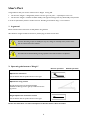
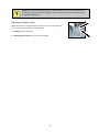
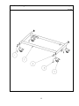
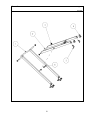
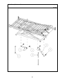
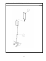
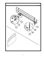
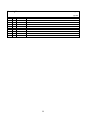
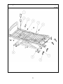
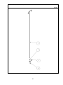
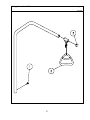
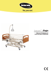
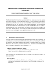
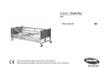
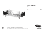
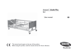
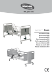
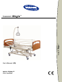
Invacare Alegio™
Invacare® Alegio™
®
User's Manual (GB)
Invacare®EC-Høng A/S
Ident. no.: 1427727
Version 02 02.2004
Product Certificate
Congratulations with your new bed Invacare®Alegio™ from
Invacare® EC-Høng A/S.
Your new bed Invacare®Alegio™ is
-marked in accordance with directive
93/42/EØF of 27th February 2002 concerning medical devices.
Furthermore, Invacare®Alegio™ is a class 1 product also in accordance with directive
93/42/EØF of 27th February 2002 concerning medical devices.
Invacare®Alegio™ has been developed and constructed with consideration for the user
and others handling or assisting with the bed. Invacare®Alegio™ has been developed in
accordance with the European Standard EN 1970.
Throughout the entire production process Invacare®Alegio™ has been supervised and
quality controlled and the finished bed has been inspected by our finished goods control.
Design plate and QA-mark are put on the bed confirming that the finished goods control
has approved the bed.
Please read the entire user’s manual before using the bed.
Invacare® EC-Høng A/S is certified according to ISO 9001 and DS/ISO13485.
Kind regards
René Engskov
Managing Director
Carsten Borup
Quality Manager
Table of Contents
User’s Part ................................................................................................................................ 4
1.
In general ................................................................................................................................... 4
2.
Operating the Invacare®Alegio™ ....................................................................................... 4
Technical Part ........................................................................................................................ 6
3.
Product information ............................................................................................................... 6
4.
Safety guidelines ...................................................................................................................... 6
5.
Dismounting/mounting the Invacare®Alegio™................................................................ 7
6.
Mounting/dismounting the accessories .............................................................................. 10
7.
Emergency lowering of the backrest ................................................................................ 10
8.
Operating the accessories .................................................................................................... 11
9
Order numbers for accessories .......................................................................................... 11
10. Cleaning .................................................................................................................................... 12
11. Maintenance and check-ups ................................................................................................. 12
12. Maintenance chart .................................................................................................................. 13
13. Trouble-shooting the electrical system ............................................................................. 14
14. Technical specifications ......................................................................................................... 14
15. Electrical data .......................................................................................................................... 15
16. Weight ...................................................................................................................................... 15
17. Spare Part List ......................................................................................................................... 16
3
User’s Part
Congratulations with your choice of the Invacare®Alegio™nursing bed.
•
•
The Invacare®Alegio™is designed for patients over the age of 12 years — especially for home care.
The Invacare®Alegio™combines excellent stability and ergonomic design with easy disassembly and operation.
In order to optimise the patient’s comfort Invacare®EC-Høng recommends using a 17-cm mattress.
1. In general
Please read the entire User’s Part carefully before using the bed.
All indications of right and left are based on a patient lying on the back in the bed.
Invacare®EC-Høng accepts no liability for any use, change or assembly of the product other
than as stated in this User’s Manual.
The bed must be blocked during nursing a patient in the bed and when it is adjusted.
2. Operating the Invacare®Alegio™
Electric operation
Manual operation
Adjustment of backrest
Use the button with the symbol shown on the right.
Adjustment of leg section
UP: Lift the leg section to the desired height.
DOWN: Lift the leg section right up and then lower the
leg section.
Height adjustment of mattress section
Use the button with the symbol shown on the right.
Please note that there is a risk of entrapment in the base frame’s shear arm lifter.
4
Always leave the bed in the lowest position. Otherwise there is a risk of entrapment due to
accidental lowering of the mattress support. A person under the bed can be seriously injured
during height adjustments.
2.
Operating the braking castors
When the bed is correctly positioned, at least one castor at the head end
and one castor at the foot end must be blocked.
1. Braking: Step on the brake.
2. Releasing the brake: Step on the release handle.
1.
5
Technical Part
Invacare®EC-Høng is certified according to DS/EN ISO 9001/EN 13485 which ensures our customers are always
supplied with products of uniform quality.
Throughout the entire production process our materials/products are quality controlled by the operators.
Furthermore there is a final test when the product is fully assembled.
The operator carrying out the final test, which comprises checking of all moveable
parts, motors and castors, puts his personal QA number on the product thereby
confirming its quality.
QA XXX
If the product does not correspond to the quality demands of Invacare®EC-Høng, it
will be discarded.
Please contact your Invacare® supplier if, contrary to our expectations, a problem should arise in connection with
the delivered product.
3. Product information
Please read the entire technical part carefully before using or servicing the bed.
All indications of right and left are based on a patient lying on the back in the bed.
•
•
•
The Invacare®Alegio™is
-marked in accordance with directive 93/42/EØF of 27th February 2002
concerning Medical Apparatus.
The motors and the control box of the Invacare®Alegio™are approved according to
EN 60601:1996-03.
The Invacare®Alegio™has undergone a risk analysis according to EN 1441.
The control box and the motors are protected according to IP 54. The hand control according to IP66.
A lock cam must be used on the control box. Otherwise, Invacare®EC-Høng cannot guarantee the protection.
Max. load: 170 kg. – max. patient weight: 135 kg. Max. load is stated on the design plate.
Note! The max. load of the bed must not be exceeded.
4. Safety guidelines
Disconnect the plug from the mains before moving the bed. The cable must be kept clear off the
floor and the castors during transport.
Make sure that the mains cable cannot be jammed or in any other way damaged,
when the bed is used.
The bed must be blocked during nursing a patient in the bed and when it is adjusted.
6
Adjust all mattress support sections to a horizontal position before transporting an assembled bed.
Hold the top of the bed end with both hands while the bed is pushed/pulled.
Only personnel who have been trained or instructed by Invacare® may perform the service work described in this
manual in the chapters 12 and 13.
If the functions of the bed change, check the bed according to chapter 12.
The Invacare®Alegio™must be stored in a room with a humidity of 10 - 80% and with a temperature of
0 - 50°C.
5. Dismounting/mounting the Invacare®Alegio™
Dismounting the Invacare®Alegio™
1.
2.
3.
4.
5.
6.
7.
8.
9.
Brake the bed and bring it to its lowest position and then about 5 cm up (1).
Remove the accessories: Siderails, bed ends and lifting pole.
Dismount the thumbscrews at both sides (2).
Dismount the cable from the lifting motor (3).
Dismount the top frame at the head end and place it in a vertical position (4,5).
Lift the leg section and dismount the locking pin (6).
Dismount the top frame at the foot end and place it in a vertical position (7).
Manual removal of the base (8).
Dismount the shear arm (9, 10, 11, 12, 13).
1.
2.
Thumb screw
Cable
3.
7
4.
5.
6.
7.
8.
8
9.
11.
10.
13.
12.
14.
Mounting the Invacare®Alegio™
1.
2.
3.
4.
5.
6.
Mount the shear arm (13, 12, 11, 10, 9).
Mount the leg section and the locking pins (7,6).
Mount the head section (5, 4).
Push the head section into the leg section (14).
Mount the cable for the lifting motor (3).
Mount the accessories: Siderails, bed ends and lifting pole.
9
6. Mounting/dismounting the accessories
Mounting the Vibeke wooden bed end
Lower the bed ends into the U-profiles.
Mounting the Eclipse2 metal side rail
The side rail may be mounted with the release system at the head of the bed.
The fork links on the side rail must be mounted according
to the instruction on the side rail.
1)
0-6 cm
2)
25 cm or more
1)
2)
Tighten the side rail with 2 thumbscrews.
There is a risk of entrapment on assembly and operation of the side rails.
Mounting the lifting pole
Lower the lifting pole into the lifting pole tube. The lifting pole MUST be fastened with a thumbscrew.
Position the lifting pole in such a way that the handle extends inwards across the bed.
If the lifting pole is used while the handle has been turned away from the bed the bed can tip
when the handle is used.
7. Emergency lowering of the backrest
A minimum of 2 persons is required to release a mattress support.
Remove the patient before emergency release of the mattress support.
Remove the plug from the mains before emergency release of the mattress support.
In an emergency the mattress sections are released by pulling out the
cotter pin from the motor.
Both persons hold the mattress section in locked position. One of them
pulls out the cotter pin. Both slowly lower the mattress section until it is
complete down.
10
8. Operating the accessories
Operating the Eclipse2 wooden side rail
UP: Pull the top tube of the side rail towards the end where the release system is.
DOWN: Press the release button down while pulling the top tube away from the release system.
Check that the side rails have been locked correctly!
There is a risk of entrapment while operating the side rails.
If the side rail is mounted with the lock in the foot end it might
hit the braking pedal at the head end.
Adjusting the height of the lifting pole handle
Loosen the cord as shown in ill. A. The lifting handle can now be
adjusted to the desired height. Press the cord together as shown in
ill. B and check that the cord is locked in the cord lock by pulling
the handle.
Position the lifting pole in such a way that the handle
extends inwards across the bed. If the handle has
been turned away from the bed while the lifting pole
is being used, the bed can tip.
Max. load of the lifting pole: 80 kg.
A
9. Order numbers for accessories
Article
Order no.
Siderail Eclipse2
50.55700.D0
Bed end Vibeke
1427649-0102
Lifting pole
50.57600.D0
Hand control support
1427692-1015
IV Drop
50.60030.D0
Support for IV Drop
50.60910.00
Please only use original spare parts.
Spare parts lists and extra user manuals for the Invacare®Alegio™can be ordered from Invacare®.
11
B
10. Cleaning
The Invacare®Alegio™does not tolerate cleaning in automatic washing plants or using water-jet based cleaning
equipment.
The bed is washed down using a sponge, cloth or brush. Use ordinary household detergents.
Dry the bed after cleaning.
Never use acids, alkalines or solvents such as acetone or cellulose thinner.
The hand control, motors and the control box can be wiped with a moist cloth (the water temperature must be
below 30° C).
When cleaning: Bring the backrest to its top position. Bring the bed to its top position. Disconnect the power
supply by pulling the plug from the wall before cleaning the bed. The risk of entrapment of fingers is minimised, as
accidental elevation of parts of the bed not is possible.
11. Maintenance and check-ups
Only personnel who have received the necessary instruction or training may perform service and maintenance on
the Invacare® Alegio™.
After 3 months of use the following must be checked:
- Tightening of the thumbscrews at the inserts in the middle of the bed
- Fastening of the siderail, locking system and moving system.
With normal operation the first service inspection is required after 2 years and thereafter every year.
Please note:
The mattress support must be supported during service inspections to prevent accidental lowering.
For beds with electrical equipment a safety test comprising control of the motors’ performance and mechanical
state is recommended once a year.
Motors, control box and hand control
These parts are serviced by exchanging the faulty part.
Motors, control box and hand control must be regularly cleaned from dust and dirt and must be inspected for
mechanical damage or breakage.
Inspect anchor points, cables, piston rod, casing and plugs and check the correct functioning of the motor.
12
12. Maintenance chart
Only personnel who have received the necessary instruction or training may perform service
and maintenance on the Invacare® Alegio™.
Bed / ID no: _______________________________
What to check for:
Date:
Check the siderails’ mounting and locking/movement
Check mounting and braking of wheels
Check height adjustment motor, suspension, and performance
Check backrest motor, suspension and performance
Check that cables and plugs are undamaged
Check rastofix fitting and its function
Check weldings
Damaged coating repaired
Lubrication performed:
1) Points of rotation in mattress support and base frame, with oil.
2) All of the motors’ tension rods, with oil.
Lubricate with medically clean oil, e.g. KEN-WO 50,
order no.: 813239.
A service contract can be made in countries where Invacare® has its own sales company.
Furthermore, Invacare® offers courses in service and maintenance of the Invacare® Alegio™.
13
13. Trouble-shooting the electrical system
Only personnel who have received the necessary instruction or training may perform service and maintenance on
the Invacare® Alegio™.
Motor plug not
connected
Sounds from
the relay
Defective motor
No motor sounds
Defective
control unit
Motor does
not run
No relay sounds
Defective
hand control
Piston rod
does not move
Motor sounds
Defective motor
14. Technical specifications
All measurements are in given in cm. All angles are stated in degrees. All measurements and angles are stated
without tolerances.
Invacare® reserves the right to change the stated measurements and angles.
14
15. Electrical data
Voltage supply: 230 V = ±10%, 50 Hz.
Max. current input: 1 A
Voltage output: 24V
Intermittent (periodic motor operation): 10% max. 6 minutes/hour
Protection class: IP54, IP 66
Insulation class: II, type B
Sound level < 45 dB
The bed is not provided with a mains switch, so the mains plug is the only separation from the mains.
The patient is not separated from the ground and the chassis.
Double insulated
Max. load: 170 kg – see sign on design plate.
Max. load (SWL) (Patient + mattress + side rail + lifting pole + other equipment)
16. Weight
Complete bed (mattress support, base, bed ends) excl. accessories
60,0 kg
Mattress support
Top frame – head section
Top frame – leg section
Base and shear arm
Base
Shear arm
Bed ends Vibeke (pcs.)
Side rails Eclipse2 (pcs.)
Lifting pole
31,5 kg
18,5 kg
13,0 kg
28,5 kg
13,5 kg
15,0 kg
6,0 kg
7,0 kg
7,0 kg
15
Contents for Alegio bed – Spare Part List
Page
Information about using this list............................................................................................... 16
Base Frame............................................................................................................................16 - 17
Braking Castor .....................................................................................................................16 - 17
Shear Arm.............................................................................................................................18 - 19
½ Mattress Support, Head end........................................................................................20 - 21
½ Mattress Support, Leg end ..........................................................................................22 - 23
Raising Unit...........................................................................................................................22 - 23
HiLo Motor .........................................................................................................................24 - 25
Backrest Motor ..................................................................................................................24 - 25
Control Unit.........................................................................................................................26 - 27
Cables ...................................................................................................................................26 - 27
Hand Control.......................................................................................................................28 - 29
Support for Hand Control ................................................................................................28 - 29
Vibeke Wooden Bed ends ................................................................................................30 - 31
Eclipse2 Side rail ..................................................................................................................30 - 31
Mounting Parts.....................................................................................................................32 - 33
IV Drop..................................................................................................................................34 - 35
Support for IV Drop...........................................................................................................34 - 35
Lifting Pole – Model 5760..................................................................................................36 - 37
16
Information about using this list
Order of wearing parts/exchange kit:
In the table of contents on page 2 you can see where in the list you can find the wanted part/kit.
Wearing parts are sold in exchange kits with an order number for the entire kit.
The order number is as shown below marked with light grey background:
Order of spare parts:
In the table of contents on page 2 you can see where in the list you can find the wanted part. Spare parts are sold
individuallly.
The order number is as shown below marked with dark grey background:
Mounting Parts
Page 1/2
July 2002
Pcs.
2
8
4
2
2
2
2
2
Ident. no.:
421837
1423842
319155
1427655
1423980
804410
819404
819456
Description
Bearing bush
Rotate bush
Guide shoe
Thumbscrew
Handle for mattress
Ferrules 50x30x1
Ferrules 50x30x3
Pipe pin - ø8
Order of a complete unit:
In the table of contents on page 2 you can see where in the list you can find the wanted unit of the bed.
The order number is as shown below marked with grey background:
Lifting Pole – Model 5760
Page 1/2
Lifting pole – Model 5760, complete: 50.57600.D0
Exchange kit Ident. No.020028
Pcs.
Description
1
Thumbscrew M6x16
1
Handle for lifting pole, incl. suspension and lock
1
Ferrule for lifting pole
July 2002
Painted parts and wooden parts:
In the table of contents on page 2 you can see where in the list you can find the wanted part. Wooden parts are sold
individuallly.
Vibeke Wooden Bed End
Page 1/2
July 2002
Pcs.
1
Ident. no.:
1427649-0102
Description
Vibeke wooden bed end
17
Base Frame
Page 1/2
Ident no.: 1427709
July 2002
Pos.
1
2
3
4
5
Pcs.
2
1
2
4
4
Description
Ferrules 50x30x1
Base frame
Ferrules 50x30x3
Screw M12
Braking castor - ø100
Braking Castor
Ident. no.: 1427713
July 2002
Pos.
4
5
Pcs.
2
4
Description
Screw M12
Braking castor - ø100
18
Base Frame, Braking Castor
Page 2/2
July 2002
19
Shear Arm
Page 1/2
Ident. no.: 1427712
July 2002
Pos.
1
2
3
4
5
6
Pcs.
1
1
4
8
4
2
Description
Outer shear arm
Inner shear arm
Guide shoe
Rotate bush
Pipe pin - ø8
Bearing bush
20
Shear Arm
Page 2/2
July 2002
21
½ Mattress Support – Head End
Page 1/2
Ident. no.: 1427710
July 2002
Pos.
1
2
3
Pcs.
1
1
2
Description
Head section with back rest mounted
Butt knob (grey)
Thumbscrew
½ Mattress Support – Leg End
Ident. no.: 1427711
July 2002
Pos.
3
4
5
6
7
Pcs.
2
1
2
1
2
Description
Thumbscrew
Leg section with feet rest mounted
Butt knob (grey)
Raise fitting
Pipe pin - ø8
Raising Unit
Ident. no.: 1427714
July 2002
Pos.
6
7
Pcs.
1
2
Description
Raise fitting
Pipe pin – ø6
22
½ Mattress Support – Head End, ½ Mattress Support – Leg End, Raising Unit
Page 2/2
July 2002
23
Backrest Motor
Page 1/2
Ident. no.: 1427717
July 2002
Pos.
1
2
3
Pcs.
1
1
2
Description
Cable of the backrest motor (length 0.27m)
Backrest motor
Pipe pin - ø10
HiLo Motor
Ident no.: 1427715
July 2002
Pos.
4
5
6
Pcs.
1
2
1
Description
Cable of the HiLo motor (length 1.25m)
Pipe pin - ø10
Motor
24
HiLo Motor, Backrest Motor
Page 2/2
July 2002
25
Control Unit
Page 1/2
Ident. no.: 1427716
July 2002
Pos.
1
2
5
6
Pcs.
1
1
1
1
Description
Control unit
Main cable (length 3.2m)
Blind plug
Lock cam
Cables
July 2002
Pos.
2
3
4
5
6
7
Pcs.
1
1
1
1
1
1
Ident. no.:
821283
1423813
1423812
1427602
1423968
1427705
Description
Main cable (length 3.2m)
Cable of the HiLo motor (length 1.25m)
Cable of the backrest motor (length 0.27m)
Blind plug
Lock cam
Mounting clip
26
Control Unit, Cables
Page 2/2
July 2002
27
Hand Control for Control Unit CB09
Page 1/2
July 2002
Pos.
1
Pcs.
1
Ident. no.:
1423814
Description
Hand Control
Support for Hand Control
July 2002
Pos.
2
Pcs.
1
Ident. no.:
1427692-1015
Description
Support for Hand Control
28
Hand Control for Control Unit CB09, Support for Hand Control
Page 2/2
July 2002
29
Vibeke Wooden Bed End
Page 1/2
July 2002
Pcs.
1
Ident. no.:
1427649-0102
Description
Vibeke wooden bed end
Eclipse2 Side rail
Eclipse2 Side rail, complete: 50.55700.D0
Insertion kit – Ident. no.: 1427718
Pos.
Pcs. Description
1
2
Thumbscrew
2
2
Plast insert
3
2
Cylinder nut
July 2002
Eclipse2 Side rail
Eclipse2 Side rail, complete: 50.55700.D0
Locking kit – Ident. no.: 1427719
Pos.
Pcs. Description
4
1
Ratchet lock
5
1
Spring
6
1
Locking button
7
1
Guiding
July 2002
30
Vibeke Wooden Bed End, Eclipse2 Side rail
Page 2 of 2
July 2002
31
Mounting Parts
Page 1/2
July 2002
Pos.
1
2
3
4
5
6
7
8
9
10
Pcs.
1
1
2
4
2
2
8
4
2
2
Ident. no.:
1423814
1427692-1015
1423980
319155
1427655
421837
1423842
819456
819404
804410
Description
Hand Control
Support for Hand Control
Handle for mattress
Guide shoe
Thumbscrew
Bearing bush
Rotate bush
Pipe pin - ø8
Ferrules 50x30x3
Ferrules 50x30x1
32
Mounting Parts
Page 2/2
July 2002
33
IV Drop
Page 2/2
Ident. no.: 50.60030.D0
July 2002
Pos.
1
2
Pcs.
1
1
Description
IV drop bar
Ferrule
Support for IV Drop
Ident. no.: 50.60910.00
July 2002
Pos.
3
4
Pcs.
1
1
Description
Screw
Support
34
IV Drop, Support for IV Drop
Page 2/2
July 2002
35
Lifting Pole – Model 5760
Page 1/2
Lifting pole – Model 5760, complete – Ident. no.: 50.57600.D0
Exchange kit – Ident. no.: 020028
Pos.
Pcs.
Description
1
1
Thumbscrew M6x16
2
1
Handle for lifting pole, incl. suspension and lock
3
1
Ferrule for lifting pole
36
July 2002
Lifting Pole – Model 5760
Page 2/2
July 2002
37
Customer Sales and Service
INVACARE A/S
Sdr. Ringvej 39
DK-2605 Brøndby
Phone: +45 36 90 00 00
Fax: +45 36 90 00 01
INVACARE N.V.
Autobaan 14
B-8210 Loppem, Brügge
Phone: +32 50 83 10 10
Fax: +32 50 83 10 11
INVACARE Poirier S.A.
Les Roches
F-37230 Fondettes
Phone: +33 2 47 62 64 66
Fax: +33 2 47 42 12 24
INVACARE AB
Fagerstagatan 9 / Box 66
S-163 91 Spånga
Phone: +46 8 761 70 90
Fax: +46 8 761 81 08
INVACARE B.V.
Celsiusstraat 46
NL-6716 BZ Ede
Phone: +31 318 69 5 757
Fax: +31 318 69 5 758
INVACARE MECCSAN S.R.L.
Via dei Pini 62
I-36016 Thiene (VI)
Phone: +39 0445 380059
Fax: +39 0445 380034
INVACARE AS
Grensesvingen 9
P.O. Box 6230 / Etterstad
N-0603 Oslo
Phone: +47 22 57 95 00
Fax: +47 22 57 95 01
INVACARE Deutschland
GmbH
Dehmer Strasse 66
D-32549 Bad Oeynhausen
Phone: +49 57 31 754 0
Fax: +49 57 31 754 150
INVACARE LTD
South Road
Bridgend Industrial Estate
UK-Bridgend, CF31 3PY
Phone: +44 1 656 664 321
Fax: +44 1 656 667 532
INVACARE S.A.
Cl Areny s/n
Pol.industrial de Celrà
17460 Celrà (Girona-Spain)
Tel: +34 972 493200
Fax: +34 972 493220
Manufacturer:
INVACARE EC-Høng A/S
Østergade 3
DK-4270 Høng
www.invacare.com