1
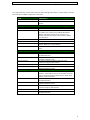
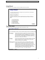
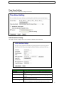
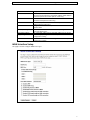
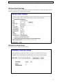
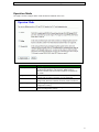
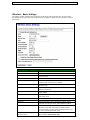
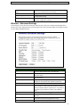
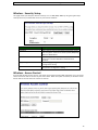
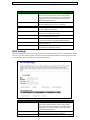
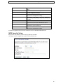
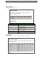
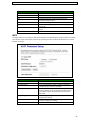
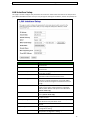
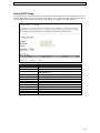
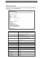
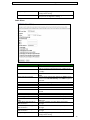
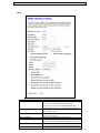
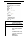
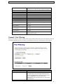
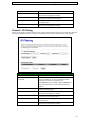
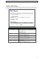
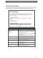
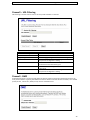
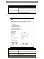
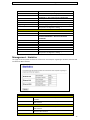
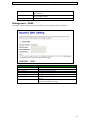
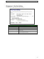
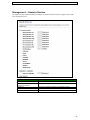
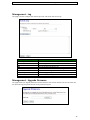
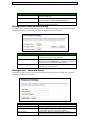
POWERLINK Outdoor CPE 2.4GHz 802.11b/g/n Before Start to Configure The WLAN Broadband Router is delivered with the following factory default parameters on the Ethernet LAN interfaces. Default IP Address: 192.168.1.254 Default IP subnet mask: 255.255.255.0 WEB login User Name: <empty> WEB login Password: <empty> The device has three operation modes (Gateway/Bridge/WISP). The default IP addresses for the device are 192.168.1.254, so you need to make sure the IP address of your PC is in the same subnet as the device, such as 192.168.1.X. It will take about 55 seconds to complete the boot up sequence after power on. Prepare your PC to configure the WLAN Broadband Router For OS of Microsoft Windows 95/ 98/ Me: 1. 2. Click the Start button and select Settings, then click Control Panel. The Control Panel window will appear. Note: Windows Me users may not see the Network control panel. If so, select View all Control Panel options on the left side of the window Move mouse and double-click the right button on Network icon. The Network window will appear. 3. 4. 5. 6. 7. 8. Check the installed list of Network Components. If TCP/IP is not installed, click the Add button to install it; otherwise go to step 6. Select Protocol in the Network Component Type dialog box and click Add button. Select TCP/IP in Microsoft of Select Network Protocol dialog box then click OK button to install the TCP/IP protocol, it may need the Microsoft Windows CD to complete the installation. Close and go back to Network dialog box after the TCP/IP installation. Select TCP/IP and click the properties button on the Network dialog box. Select Specify an IP address and type in values as following example. IP Address: 192.168.1.1, any IP address within 192.168.1.1 to 192.168.1.253 is good to connect the Wireless LAN Access Point. IP Subnet Mask: 255.255.255.0 Click OK and reboot your PC after completes the IP parameters setting. For OS of Microsoft Windows 2000, XP: 1. 2. 3. 4. 5. 6. 7. 8. Click the Start button and select Settings, then click Control Panel. The Control Panel window will appear. Move mouse and double-click the right button on Network and Dial-up Connections icon. Move mouse and double-click the Local Area Connection icon. The Local Area Connection window will appear. Click Properties button in the Local Area Connection window. Check the installed list of Network Components. If TCP/IP is not installed, click the Add button to install it; otherwise go to step 6. Select Protocol in the Network Component Type dialog box and click Add button. Select TCP/IP in Microsoft of Select Network Protocol dialog box then click OK button to install the TCP/IP protocol, it may need the Microsoft Windows CD to complete the installation. Close and go back to Network dialog box after the TCP/IP installation. Select TCP/IP and click the properties button on the Network dialog box. Select Specify an IP address and type in values as following example. IP Address: 192.168.1.1, any IP address within 192.168.1.1 to 192.168.1.253 is good to connect the Wireless LAN Access Point. IP Subnet Mask: 255.255.255.0 Click OK to completes the IP parameters setting. 2 POWERLINK Outdoor CPE 2.4GHz 802.11b/g/n For OS of Microsoft Windows NT: 1. Click the Start button and select Settings, then click Control Panel. The Control Panel window will appear. 2. Move mouse and double-click the right button on Network icon. The Network window will appear. Click Protocol tab from the Network window. 3. Check the installed list of Network Protocol window. If TCP/IP is not installed, click the Add button to install it; otherwise go to step 6. 4. Select Protocol in the Network Component Type dialog box and click Add button. 5. Select TCP/IP in Microsoft of Select Network Protocol dialog box then click OK button to install the TCP/IP protocol, it may need the Microsoft Windows CD to complete the installation. Close and go back to Network dialog box after the TCP/IP installation. 6. Select TCP/IP and click the properties button on the Network dialog box. 7. Select Specify an IP address and type in values as following example. IP Address: 192.168.1.1, any IP address within 192.168.1.1 to 192.168.1.253 is good to connect the Wireless LAN Access Point. IP Subnet Mask: 255.255.255.0 8. Click OK to complete the IP parameters setting. For OS of Microsoft Windows Vista and Windows 7 1. Click Start Button and select Control Panel, the Control Panel windows pop up. 2. From Network and Internet category choose View network status and tasks. 3. Select Change adapter settings, right click Local Area Connection, select Properties 4. From popup menu in Networking tab select Internet Protocol Version 4 (TCP/IPv4) then click Properties. 5. Check Use the following IP address then Specify IP address as following example. Enter your IP Address; the IP Address can be any number within the range from 192.168.1.1 to 192.168.1.253. IP Subnet Mask: 255.255.255.0 Click OK to complete the IP parameters setting. 3 POWERLINK Outdoor CPE 2.4GHz 802.11b/g/n This page shows the current status and some basic settings of the device, includes system, wireless, Ethernet LAN and WAN configuration information. Item Description Uptime Firmware version It shows the duration since WLAN Broad It shows the firmware version of WLAN Broadband Router. Wireless Configuration Mode Band SSID Channel Number Encryption BSSID Associated Clients TCP/IP configuration Attain IP Protocol IP Address Subnet Mask Default Gateway DHCP Server MAC Address WAN configuration Attain IP Protocol IP Address Subnet Mask Default Gateway DNS1/DNS2/DNS3 MAC Address It shows wireless operation mode It shows wireless operation mode It shows the SSID of this WLAN Broadband Router. The SSID is the unique name of WLAN Broadband Router and shared among its service area, so all devices attempts to join the same wireless network can identify it. It shows the wireless channel connected currently. It shows the status of encryption function. It shows the BSSID address of the WLAN Broadband Router. BSSID is a six-byte address. It shows the number of connected clients (or stations, PCs). It shows type of connection. It shows the IP address of LAN interfaces of WLAN Broadband Router. It shows the IP subnet mask of LAN interfaces of WLAN Broadband Router. It shows the default gateway setting for LAN interfaces outgoing data packets. It shows the DHCP server is enabled or not. It shows the MAC address of LAN interfaces of WLAN Broadband Router. It shows how the WLAN Broadband Router gets the IP address. The IP address can be set manually to a fixed one or set dynamically by DHCP server or attain IP by PPPoE / PPTP connection. It shows the IP address of WAN interface of WLAN Broadband Router. It shows the IP subnet mask of WAN interface of WLAN Broadband Router. It shows the default gateway setting for WAN interface outgoing data packets. It shows the DNS server information. It shows the MAC address of WAN interface of WLAN Broadband Router. 4 POWERLINK Outdoor CPE 2.4GHz 802.11b/g/n Setup Wizard This page guides you to configure wireless broadband router for first time Operation Mode This page followed by Setup Wizard page to define the operation mode. 5 POWERLINK Outdoor CPE 2.4GHz 802.11b/g/n Time Zone Setting This page is used to enable and configure NTP client LAN Interface Setup This page is used to configure local area network IP address and subnet mask Item Description IP Address Subnet Mask Fill in the address of LAN interfaces of this WLAN Access Point. Fill in the subnet mask of LAN interfaces of this WLAN Access Point. Fill in the default gateway for LAN interfaces out going data packets. Click to select Disabled, Client or Server in different operation mode of wireless Access Point. Fill in the start IP address and end IP address to allocate a range of IP addresses; client with DHCP function set will be Default Gateway DHCP DHCP Client Range 6 POWERLINK Outdoor CPE 2.4GHz 802.11b/g/n Show Client Static DHCP Set Static DHCP Domain Name 802.1d Spanning Tree Clone MAC Address Apply Changes Reset assigned an IP address from the range. Click to open the active DHCP Client Table window that shows the active clients with their assigned IP address, MAC address and time expired information.[Server mode only] Select enable or disable the Static DHCP function from pull-down menu[Server mode only] Manual setup Static DHCP IP address for specific MAC address.[Server mode only] Assign Domain Name and dispatch to DHCP clients. It is optional field. Select enable or disable the IEEE 802.1d Spanning Tree function from pull-down menu. Fill in the MAC address that is the MAC address to be cloned Click the Apply Changes button to complete the new configuration setting Click the reset button to abort change and recover the previous configuration setting. WAN Interface Setup This page is used to configure WAN access type 7 POWERLINK Outdoor CPE 2.4GHz 802.11b/g/n Wireless Basic Settings This page is used to configure basic wireless parameters like Band, Mode, Network Type SSID, Channel Number, Enable Mac Clone (Single Ethernet Client). Wireless Security Setup This page is used to configure wireless security 8 POWERLINK Outdoor CPE 2.4GHz 802.11b/g/n Operation Mode This page is used to configure which mode wireless broadband router acts Item Description Gateway Traditional gateway configuration. It always connects internet via ADSL/Cable Modem. LAN interface, WAN interface, Wireless interface, NAT and Firewall modules are applied to this mode Each interface (LAN, WAN and Wireless) regards as bridge. NAT, Firewall and all router’s functions are not supported Switch Wireless interface to WAN port and all Ethernet ports in bridge mode. Wireless interface can do all router’s functions Click the Apply Changes button to complete the new configuration setting. Click the Reset button to abort change and recover the previous configuration setting. Bridge Wireless ISP Apply Changes Reset 9 POWERLINK Outdoor CPE 2.4GHz 802.11b/g/n Wireless - Basic Settings This page is used to configure the parameters for wireless LAN clients that may connect to your Broadband Router. Here you may change wireless encryption settings as well as wireless network parameters. Item Description Disable Wireless LAN Interface Band Mode Click on to disable the wireless LAN data transmission. Click to select 2.4GHz(B) / 2.4GHz(G) /2.4GHz(B+G) Click to select the WLAN AP / Client / WDS / AP+WDS wireless mode. Click to enable multiple AP. While network is selected to be client. Click to select network type infrastructure or Ad-Hoc It is the wireless network name. The SSID can be 32 bytes long. Select the operational bandwidth 20MHz or 40MHz (802.11n band only) Select the sideband with upper or lower for channel width 40MHz. Select the wireless communication channel from pull-down menu. Click to enable or disable the SSID broadcast function Click to enable or disable WMM function Select transmission data rate from pull-down menu. Data rate can be auto select, 1M to 54Mbps or MCS. Click the Show Active Clients button to open Active Wireless Client Table that shows the MAC address, transmit-packet, receive-packet and transmission-rate for each associated wireless client. Take Laptop NIC MAC address as wireless client MAC address. [Client Mode only] Multiple AP Network Type SSID Channel width Control Sideband Channel Number Broadcast SSID WMM Data Rate Associated Clients Enable Mac Clone (Single Ethernet Client) 10 POWERLINK Outdoor CPE 2.4GHz 802.11b/g/n Enable Universal Repeater Mode SSID of Extended Interface Apply Changes Reset Click to enable Universal Repeater Mode. (Acting as AP and client simultaneously in this mode). Assign SSID when enables Universal Repeater Mode. Click the Apply Changes button to complete the new configuration setting. Click the Reset button to abort change and recover the previous configuration setting. Wireless - Advanced Settings These settings are only for more technically advanced users who have a sufficient knowledge about wireless LAN. These settings should not be changed unless you know what effect the changes will have on your WLAN Broadband Router. Item Fragment Threshold RTS Threshold Beacon Interval Preamble Type IAPP Protection Aggregation Short GI WLAN Partition RF Output power Description Set the data packet fragmentation threshold, value can be written between 256 and 2346 bytes. Set the RTS Threshold, value can be written between 0 and 2347 bytes. Set the Beacon Interval, value can be written between 20 and 1024ms. Click to select the Long Preamble or Short Preamble support on the wireless data packet transmission. Click to enable or disable the IAPP function. Protection is for neighboring 802.11b wireless network. Select disable to reduce the adverse affect of legacy wireless network 802.11n performance. This option is available only when 802.11 mode is set to 802.11n only Click to enable or disable aggregation function. Click to enable or disable short Guard Intervals function Enabling WLAN Partition prevents associated wireless clients from communicating with each other. To adjust transmission power level. 11 POWERLINK Outdoor CPE 2.4GHz 802.11b/g/n Wireless - Security Setup This page allows you setup the wireless security. Turn on WEP, WPA; WPA2 by using encryption keys could prevent any unauthorized access to your wireless network. Item Select SSID Encryption Use 802.1x Authentication Apply Changes Reset Description Select SSID to be encrypted from multiple APs. Select the encryption supported over wireless access. The encryption method can be None, WEP, WPA(TKIP), WPA2 or WPA2 Mixed While Encryption is selected to be WEP. Click the check box to enable IEEE 802.1x authentication function. Click the Apply Changes button to complete the new configuration setting. Click the Reset button to abort change and recover the previous configuration setting. Wireless - Access Control If you enable wireless access control, only those clients whose wireless MAC addresses are in the access control list will be able to connect to your Access Point. When this option is enabled, no wireless clients will be able to connect if the list contains no entries. 12 POWERLINK Outdoor CPE 2.4GHz 802.11b/g/n Item Description Wireless Access Control Mode Click the Disabled, Allow Listed or Deny Listed of drop down menu choose wireless access control mode. This is a security control function; only those clients registered in the access control list can link to this WLAN Broadband Router. Fill in the MAC address of client to register this WLAN Broadband Router access capability. Enter notes for the registered client. Click the Apply Changes button to register the client to new configuration setting. Click the Reset button to abort change and recover the previous configuration setting. It shows the registered clients that are allowed to link to this WLAN Broadband Router. Click to delete the selected clients that will be access right removed from this WLAN Broadband Router. Click to delete all the registered clients from the access allowed list. Click the Reset button to abort change and recover the previous configuration setting. MAC Address Comment Apply Changes Reset Current Access Control List Delete Selected Delete All Reset WDS Settings Wireless Distribution System uses wireless media to communicate with other APs, like the Ethernet does. To do this, you must set these APs in the same channel and set MAC address of other AP that you want to communicate with in the table and then enable the WDS. Item Enable WDS MAC Address Data Rate Description Click the Disabled, Allow Listed or Deny Listed of drop down menu choose wireless access control mode. This is a security control function; only those clients registered in the access control list can link to this WLAN Broadband Router. Fill in the MAC address of client to register this WLAN Broadband Router access capability. Select transmission data rate from pull down menu. 13 POWERLINK Outdoor CPE 2.4GHz 802.11b/g/n Comment Apply Changes Reset Set Security Show Statistics Delete Selected Delete All Reset Data rate can be auto-selected, 1Mbps to 54Mbps or MCS. Fill in the comments for the registered client. Click the Apply Changes button to register the client to new configuration setting. Click the Reset button to abort change and recover the previous configuration setting. Click button to configure wireless security like WEP(64bits), WEP(128bits), WPA(TKIP), WPA2(AES) or None It shows the TX, RX packets, rate statistics Click to delete the selected clients that will be removed from the wireless distribution system. Click to delete all the registered APs from the wireless distribution system allowed list. Click the Reset button to abort change and recover the previous configuration setting. It shows the registered clients that are allowed to link to this WLAN Broadband Router. WDS Security Setup Requirement: Set [Wireless]->[Basic Settings]->[Mode]->AP+WDS This page is used to configure the wireless security between APs. 14 POWERLINK Outdoor CPE 2.4GHz 802.11b/g/n WDS AP Table This page is used to show WDS statistics Item MAC Address Tx Packets Tx Errors Rx Packets Tx Rate (Mbps) Refresh Close Description It shows the MAC Address within WDS. It shows the statistic count of sent packets on the wireless LAN interface. It shows the statistic count of error sent packets on the Wireless LAN interface. It shows the statistic count of received packets on the wireless LAN interface. It shows the wireless link rate within WDS. Click to refresh the statistic counters on the screen. Click to close the current window. Site Survey This page is used to scan and connect nearby APs when operate at client mode. 15 POWERLINK Outdoor CPE 2.4GHz 802.11b/g/n Item SSID BSSID Channel Type Encrypt Signal Refresh Connect Description It shows the SSID of AP. It shows BSSID of AP. It show the current channel of AP occupied. It shows which type of connection to be connect, infrastructure (AP) or ad-hoc. It shows the encryption status. It shows signal strength (expressed in percentage) of current AP. Click the Refresh button to re-scan site survey on the screen. Click the Connect button to establish connection. WPS This page allows you to change the setting for WPS (Wi-Fi Protected Setup). Using this feature could let your wireless client automatically synchronize its setting and connect to the Access Point in a minute without any hassle. Item Disable WPS WPS Status Self-PIN Number Push Button Configuration Apply Changes Reset Client PIN Number Description Click on to disable the Wi-Fi Protected Setup function Show WPS status is Configured or Unconfigured Fill in the PIN Number of AP to register the wireless distribution system access capability. The Start PBC button provides tool to scan the wireless network. If any Access Point or IBSS is found, you could connect it automatically when client join PBC mode. Click the Apply Changes button to complete the new configuration setting. Click the Reset button to abort change and recover the previous configuration setting. Fill in the Client PIN Number from your Client sites. 16 POWERLINK Outdoor CPE 2.4GHz 802.11b/g/n LAN Interface Setup This page is used to configure the parameters for local area network that connects to the LAN ports of your WLAN Broadband Router. Here you may change the setting for IP address, subnet mask, DHCP, etc. Item IP Address Subnet Mask Default Gateway DHCP DHCP Client Range Show Client Static DHCP Domain Name 802.1d Spanning Tree Clone MAC Address Apply Changes Reset Description Fill in the IP address of LAN interfaces of this WLAN Access Point. Fill in the subnet mask of LAN interfaces of this WLAN Access Point. Fill in the default gateway for LAN interfaces out going data packets. Click to select Disabled, Client or Server in different operation mode of wireless Access Point. Fill in the start IP address and end IP address to allocate a range of IP addresses; client with DHCP function set will be assigned an IP address from the range. Click to open Active DHCP Client Table window that shows current active clients with their assigned IP address, MAC address and expire time information [Server mode only] Select to enable or disable Static DHCP from pull-down menu [Server mode only] Assign Domain Name and dispatch to DHCP clients. It is optional field. Select to enable or disable the IEEE 802.1d Spanning Tree function from pull-down menu. Fill in the MAC address that is the MAC address to be cloned. Click the Apply Changes button to complete the new configuration setting. Click the Reset button to abort change and recover the previous configuration setting. 17 POWERLINK Outdoor CPE 2.4GHz 802.11b/g/n Static DHCP Setup This page allows you reserve IP addresses, and assign the same IP address to the network device with the specified MAC address any time it requests an IP address. This is almost the same as when a device has a static IP address except that the device must still request an IP address from the DHCP server Item Description Enable Static DHCP IP Address MAC Address Click to enable Static DHCP Enter the Static IP Address in the IP Address field Enter the MAC address of the corresponding Client in the MAC Address field Take notes of the setting. Click the Apply Changes button to complete the change List mapping of static IP address to corresponding clients. Assigned static IP address MAC address of corresponding client Notes of the mapping Click on checkbox if you want to delete from the list. Click to delete current selected from the list. Delete all of the entries from the list. Uncheck all of previous selections. Comment Apply Changes Static DHCP List IP Address MAC address Comment Select Delete Selected Delete All Reset 18 POWERLINK Outdoor CPE 2.4GHz 802.11b/g/n WAN Interface Setup This page is used to configure the parameters for wide area network that connects to the WAN port of your WLAN Broadband Router. Here you may change the access method to Static IP, DHCP, PPPoE or PPTP by click the item value of WAN Access Type. Static IP Item Static IP IP Address Subnet Mask Default Gateway MTU Size DNS 1 DNS 2 DNS 3 Clone MAC Address Enable uPNP Enable IGMP Proxy Enable Ping Access on WAN Enable Web server Access on WAN Enable IPsec pass through on VPN connection Enable PPTP pass through on VPN connection Enable L2TP pass through on VPN connection Description Click to select Static IP support on WAN interface. There are IP address, subnet mask and default gateway settings need to be done If you select the Static IP support on WAN interface, fill in the IP address for it. If you select the Static IP support on WAN interface, fill in the subnet mask for it If you select the Static IP support on WAN interface, fill in the default gateway for WAN interface out going data packets. Fill in the mtu size of MTU Size. The default value is 1400 Enter the IP address of Domain Name Server 1. Enter the IP address of Domain Name Server 2. Enter the IP address of Domain Name Server 3. Enter the MAC address that is the MAC address to be cloned Click the checkbox to enable uPNP function. Click the checkbox to enable IGMP proxy Click the checkbox to enable WAN IGMP response. Click the checkbox to enable web configuration from WAN side Click the checkbox to enable IPSec packet pass through Click the checkbox to enable PPTP packet pass through Click the checkbox to enable L2TP packet pass through 19 POWERLINK Outdoor CPE 2.4GHz 802.11b/g/n Apply Changes Reset Click the Apply Changes button to complete the new configuration setting. Click the Reset button to abort change and recover the previous configuration setting. DHCP Client Item DHCP Client Host Name MTU Size Attain DNS Automatically Set DNS Manually DNS 1 DNS 2 DNS 3 Clone MAC Address Enable uPNP Enable IGMP Proxy Enable Ping Access on WAN Enable Web server Access on WAN Enable IPsec pass through on VPN connection Enable PPTP pass through on VPN connection Enable L2TP pass through on VPN connection Apply Changes Description Click to select DHCP support on WAN interface for IP address assigned automatically from a DHCP server. Fill in the host name of Host Name. The default value is empty Fill in the mtu size of MTU Size. The default value is 1400 Click to select getting DNS address for DHCP support. Please select Set DNS Manually if the DHCP support is selected. Click to select getting DNS address for DHCP support. Fill in the IP address of Domain Name Server 1. Fill in the IP address of Domain Name Server 2. Fill in the IP address of Domain Name Server 3. Fill in the MAC address that is the MAC address to be cloned Click the checkbox to enable uPNP function. Click the checkbox to enable IGMP proxy Click the checkbox to enable WAN IGMP response. Click the checkbox to enable web configuration from WAN side Click the checkbox to enable IPSec packet pass through Click the checkbox to enable PPTP packet pass through Click the checkbox to enable L2TP packet pass through Click the Apply Changes button to complete the new configuration setting. 20 POWERLINK Outdoor CPE 2.4GHz 802.11b/g/n Reset Click the Reset button to abort change and recover the previous configuration setting. PPPoE Item PPPoE User Name Password Service Name Connection Type Idle Time Description Click to select PPPoE support on WAN interface. There are user name, password, connection type and idle time settings need to be done. If you select the PPPoE support on WAN interface, fill in the user name and password to login the PPPoE server. If you select the PPPoE support on WAN interface, fill in the user name and password to login the PPPoE server. Fill in the service name of Service Name. The default value is empty. Select the connection type from pull-down menu. There are Continuous, Connect on Demand and Manual three types to select. Continuous connection type means to setup the connection through PPPoE protocol whenever this WLAN Broadband Router is powered on. Connect on Demand connection type means to setup the connection through PPPoE protocol whenever you send the data packets out through the WAN interface; there are a watchdog implemented to close the PPPoE connection while there are no data sent out longer than the idle time set. Manual connection type means to setup the connection through the PPPoE protocol by clicking the Connect button manually, and clicking the Disconnect button manually. If you select the PPPoE and Connect on Demand connection type, fill in the idle time for 21 POWERLINK Outdoor CPE 2.4GHz 802.11b/g/n MTU Size Attain DNS Automatically Set DNS Manually DNS 1 DNS 2 DNS 3 Clone MAC Address Enable uPNP Enable IGMP Proxy Enable Ping Access on WAN Enable Web server Access on WAN Enable IPsec pass through on VPN connection Enable PPTP pass through on VPN connection Enable L2TP pass through on VPN connection Apply Changes Reset auto-disconnect function. Value can be between 1 and 1000 minutes. Fill in the mtu size of MTU Size. The default value is 1400 Click to select getting DNS address for DHCP support. Please select Set DNS Manually if the DHCP support is selected. Click to select getting DNS address for DHCP support. Fill in the IP address of Domain Name Server 1. Fill in the IP address of Domain Name Server 2. Fill in the IP address of Domain Name Server 3. Fill in the MAC address that is the MAC address to be cloned Click the checkbox to enable uPNP function. Click the checkbox to enable IGMP proxy Click the checkbox to enable WAN IGMP response. Click the checkbox to enable web configuration from WAN side Click the checkbox to enable IPSec packet pass through Click the checkbox to enable PPTP packet pass through Click the checkbox to enable L2TP packet pass through Click the Apply Changes button to complete the new configuration setting. Click the Reset button to abort change and recover the previous configuration setting. 22 POWERLINK Outdoor CPE 2.4GHz 802.11b/g/n PPTP Item PPTP IP Address Subnet Mask Server IP Address User Name Password Connection Type Description Allow user to make a tunnel with remote site directly to secure the data transmission among the connection. User can use embedded PPTP client supported by this router to make a VPN connection. If you select the PPTP support on WAN interface, fill in the IP address for it. If you select the PPTP support on WAN interface, fill in the subnet mask for it. Enter the IP address of the PPTP Server. If you select the PPTP support on WAN interface, fill in the user name and password to login the PPTP server. If you select the PPTP support on WAN interface, fill in the user name and password to login the PPTP server. Select the connection type from pull-down menu. 23 POWERLINK Outdoor CPE 2.4GHz 802.11b/g/n Idle Time MTU Size Request MPPE Encryption Request MPPC Compression Attain DNS Automatically Set DNS Manually DNS 1 DNS 2 DNS 3 Clone MAC Address Enable uPNP Enable IGMP Proxy Enable Ping Access on WAN Enable Web server Access on WAN Enable IPsec pass through on VPN connection Enable PPTP pass through on VPN connection Enable L2TP pass through on VPN connection Apply Changes Reset There are Continuous, Connect on Demand and Manual three types to select. Continuous connection type means to setup the connection through PPPoE protocol whenever this WLAN Broadband Router is powered on. Connect on Demand connection type means to setup the connection through PPPoE protocol whenever you send the data packets out through the WAN interface; there are a watchdog implemented to close the PPPoE connection while there are no data sent out longer than the idle time set. Manual connection type means to setup the connection through the PPPoE protocol by clicking the Connect button manually, and clicking the Disconnect button manually. The amount of time of inactivity before the device will disconnect your PPTP session. Fill in the mtu size of MTU Size. The default value is 1400 Click the checkbox to enable request MPPE encryption. Click the checkbox to enable request MPPC compression. Click to select getting DNS address for DHCP support. Please select Set DNS Manually if the DHCP support is selected. Click to select getting DNS address for DHCP support. Fill in the IP address of Domain Name Server 1. Fill in the IP address of Domain Name Server 2. Fill in the IP address of Domain Name Server 3. Fill in the MAC address that is the MAC address to be cloned Click the checkbox to enable uPNP function. Click the checkbox to enable IGMP proxy Click the checkbox to enable WAN IGMP response. Click the checkbox to enable web configuration from WAN side Click the checkbox to enable IPSec packet pass through Click the checkbox to enable PPTP packet pass through Click the checkbox to enable L2TP packet pass through Click the Apply Changes button to complete the new configuration setting. Click the Reset button to abort change and recover the previous configuration setting. L2tP Use Layer 2 Tunneling Protocol (L2TP) if your ISP uses an L2TP connection. Your ISP will provide you with a username and password. 24 POWERLINK Outdoor CPE 2.4GHz 802.11b/g/n Item L2TP IP Address Subnet Mask Server IP Address User Name Password Connection Type Idle Time Description Allow user to make a tunnel with remote site directly to secure the data transmission among the connection. User can use embedded PPTP client supported by this router to make a VPN connection. Enter L2TP IP address supplied by your ISP (Static only). Enter subnet mask. Enter L2TP Server IP address provided by your ISP. Enter L2TP service username provided by your ISP. Enter L2TP service password provided by your ISP. Select the connection type from pull-down menu. There are Continuous, Connect on Demand and Manual three types to select. Continuous connection type means to setup the connection through L2TP protocol whenever this WLAN Broadband Router is powered on. Connect on Demand connection type means to setup the connection through L2TP protocol whenever you send the data packets out through the WAN interface; there are a watchdog implemented to close the L2TP connection while there are no data sent out longer than the idle time set. Manual connection type means to setup the connection through the L2TP protocol by clicking the Connect button manually, and clicking the Disconnect button manually. The amount of time of inactivity before the device will disconnect your L2TP session. 25 POWERLINK Outdoor CPE 2.4GHz 802.11b/g/n MTU Size Attain DNS Automatically Set DNS Manually DNS 1 DNS 2 DNS 3 Clone MAC Address Enable uPNP Enable IGMP Proxy Enable Ping Access on WAN Enable Web server Access on WAN Enable IPsec pass through on VPN connection Enable PPTP pass through on VPN connection Enable L2TP pass through on VPN connection Apply Changes Change the MTU size that your ISP provided. The default value is 1400 and range is 1400 to 1460 bytes. Click to get DNS IP address automatically. Enter DNS IP address provided by your ISP manually. Enter the IP address of Domain Name Server 1. Enter the IP address of Domain Name Server 2. Enter the IP address of Domain Name Server 3. Clone MAC address of your computer. Click the checkbox to enable uPNP function. Click the checkbox to enable IGMP proxy Click the checkbox to enable WAN IGMP response. Click the checkbox to enable web configuration from WAN side Click the checkbox to enable IPSec packet pass through Click the checkbox to enable PPTP packet pass through Click the checkbox to enable L2TP packet pass through Click the Apply Changes button to complete the new configuration setting. Firewall - Port Filtering Entries in this table are used to restrict certain types of data packets from your local network to Internet through the Gateway. Use of such filters can be helpful in securing or restricting your local network. Item Enable Port Filtering Port Range Protocol, Comments Apply Changes Description Click to enable the port filtering security function. To restrict data transmission from the local network on certain ports, fill in the range of Start-port and end-port, and the protocol, also put your comments on it. The Protocol can be TCP, UDP or Both. Comments let you know about whys to restrict data from the ports. Click the Apply Changes button to register the ports 26 POWERLINK Outdoor CPE 2.4GHz 802.11b/g/n Reset Delete Selected Delete All Reset to port filtering list. Click the Reset button to abort change and recover the previous configuration setting. Click to delete the selected port range that will be removed from the port-filtering list. Click to delete all the registered entries from the port-filtering list. Click the Reset button to abort change and recover the previous configuration setting. Firewall - IP Filtering Entries in this table are used to restrict certain types of data packets from your local network to Internet through the Gateway. Use of such filters can be helpful in securing or restricting your local network. Item Enable IP Filtering Local IP Address; Protocol; Comments Apply Changes Reset Delete Selected Delete All Reset Description Click to enable the IP filtering security function. To restrict data transmission from local network on certain IP addresses, fill in the IP address and the protocol; also put your comments on it. The Protocol can be TCP, UDP or Both. Comments let you know about whys to restrict data from the IP address. Click the Apply Changes button to register the IP address to IP filtering list. Click the Reset button to abort change and recover the previous configuration setting. Click to delete the selected IP address that will be removed from the IP-filtering list. Click to delete all the registered entries from the IP-filtering list. Click the Reset button to abort change and recover the previous configuration setting. 27 POWERLINK Outdoor CPE 2.4GHz 802.11b/g/n Firewall - MAC Filtering Entries in this table are used to restrict certain types of data packets from your local network to Internet through the Gateway. Use of such filters can be helpful in securing or restricting your local network. Item Enable MAC Filtering MAC Address; Comments Apply Changes Reset Delete Selected Delete All Reset Description Click to enable the MAC filtering security function. To restrict data transmission from local network on certain MAC addresses, fill in the MAC address and your comments on it. Comments let you know about whys to restrict data from the MAC address. Click the Apply Changes button to register the MAC address to MAC filtering list. Click the Reset button to abort change and recover the previous configuration setting. Click to delete the selected MAC address that will be removed from the MAC-filtering list. Click to delete all the registered entries from the MAC-filtering list. Click the Reset button to abort change and recover the previous configuration setting. 28 POWERLINK Outdoor CPE 2.4GHz 802.11b/g/n Firewall - Port Forwarding Entries in this table allow you to automatically redirect common network services to a specific machine behind the NAT firewall. These settings are only necessary if you wish to host some sort of server like a web server or mail server on the private local network behind your Gateway's NAT firewall. Item Enable Port Forwarding Local IP Address Protocol Port Range Comment Apply Changes Reset Delete Selected Delete All Reset Description Click to enable the Port Forwarding security function. To forward data packets coming from WAN to a specific IP address that hosted in local network behind the NAT firewall, fill in the IP address, protocol, port range and your comments. The Protocol can be TCP, UDP or Both. The Port Range for data transmission. Comments let you know about whys to allow data packets forward to the IP address and port number. Click the Apply Changes button to register the IP address and port number to Port forwarding list. Click the Reset button to abort change and recover the previous configuration setting. Click to delete the selected IP address and port number that will be removed from the port-forwarding list. Click to delete all the registered entries from the port-forwarding list. Click the Reset button to abort change and recover the previous configuration setting. 29 POWERLINK Outdoor CPE 2.4GHz 802.11b/g/n Firewall – URL Filtering URL Filtering is used to restrict users to access specific websites in internet. Item Enable URL Filtering URL Address Apply Changes Reset Delete Selected Delete All Reset Description Click to enable the URL Filtering function. Add one URL address. Click the Apply Changes button to save settings. Click the Reset button to abort change and recover the previous configuration setting. Click to delete the selected URL address that will be removed from the URL Filtering list. Click to delete all the registered entries from the URL Filtering list Click the Reset button to abort change and recover the previous configuration setting. Firewall - DMZ A Demilitarized Zone is used to provide Internet services without sacrificing unauthorized access to its local private network. Typically, the DMZ host contains devices accessible to Internet traffic, such as Web (HTTP) servers, FTP servers, SMTP (e-mail) servers and DNS servers. 30 POWERLINK Outdoor CPE 2.4GHz 802.11b/g/n Item Enable DMZ DMZ Host IP Address Apply Changes Reset Description Click to enable the DMZ function. To support DMZ in your firewall design, fill in the IP address of DMZ host that can be access from the WAN interface. Click the Apply Changes button to register the IP address of DMZ host. Click the Reset button to abort change and recover the previous configuration setting. QoS Entries in this table improve your online gaming experience by ensuring that your game traffic is prioritized over other network traffic, such as FTP or Web Item Enable QoS Automatic Uplink Speed Manually Uplink Speed [Kbps] Automatic downlink Speed [Kbps] QoS Rule Setting Address Type Description Click to enable the QoS function. Click checkbox to enable uplink automatic bandwidth control. Enter uplink speed in Kbps to constrain maximum uplink bandwidth capacity. Click checkbox to enable downlink automatic bandwidth control. Select IP address or MAC address 31 POWERLINK Outdoor CPE 2.4GHz 802.11b/g/n Local IP Address MAC Address Mode Enter local IP address range Enter MAC address you are going to control. Select band width control type Guaranteed minimum bandwidth or Restricted maximum bandwidth. Enter uplink bandwidth in Kbps Enter downlink bandwidth in Kbps Give a definition to the setting Click the Apply Changes button to save the settings Click the Reset button to abort change and recover the previous configuration setting. Uplink Bandwidth Downlink Bandwidth Comment Apply Changes Reset Current QoS Rule Table Local IP Address MAC Address Mode List LAN IP address that is controlled. List MAC address that is controlled. List control type that is controlled. Guaranteed minimum bandwidth or Restricted maximum bandwidth. List uplink bandwidth List Download bandwidth Definition of the setting Click to select rule for further action. Delete selected rules. Delete all rules listed on table. Click the Reset button to abort change and recover the previous configuration setting. Uplink Bandwidth Download Bandwidth Comment Select Delete Selected Delete All Reset Management - Statistics This page shows the packet counters for transmission and reception regarding to wireless, Ethernet LAN and Ethernet WAN networks. Item Wireless LAN Sent Packets Received Packets Ethernet LAN Sent Packets Received Packets Description It shows the statistic count of sent packets on the wireless LAN interface. It shows the statistic count of received packets on the wireless LAN interface. It shows the statistic count of sent packets on the Ethernet LAN interface. It shows the statistic count of received packets on the Ethernet LAN interface. Ethernet WAN 32 POWERLINK Outdoor CPE 2.4GHz 802.11b/g/n Sent Packets Received Packets Refresh It shows the statistic count of sent packets on the Ethernet WAN interface. It shows the statistic count of received packets on the Ethernet WAN interface. Click the refresh the statistic counters on the screen. Management - DDNS This page is used to configure Dynamic DNS service to have DNS with dynamic IP address. Item Enable DDNS Service Provider Domain Name User Name/Email Password/Key Apply Change Reset Description Click the checkbox to enable DDNS service. Click the drop down menu to pick up the right provider. To configure Domain Name. Configure User Name, Email. Configure Password, Key. Click the Apply Changes button to save the enable DDNS service. Click the Reset button to abort change and recover the previous configuration setting. 33 POWERLINK Outdoor CPE 2.4GHz 802.11b/g/n Management - Time Zone Setting This page is used to configure NTP client to get current time. Item Current Time Time Zone Select Enable NTP client update NTP Server Apply Change Reset Refresh Description It shows the current time. Click the time zone in your country. Click the checkbox to enable NTP client update. R Click select default or input NTP server IP address. Click the Apply Changes button to save and enable NTP client service. Click the Reset button to abort change and recover the previous configuration setting. Click the refresh the current time shown on the screen. 34 POWERLINK Outdoor CPE 2.4GHz 802.11b/g/n Management – Denial-of-Service This page is used to enable and setup protection to prevent attack by hacker’s program. It provides more security for users. Item Enable DoS Prevention Whole System Flood/ Per-Source IP Flood Select ALL Clear ALL Apply Changes Description Click the checkbox to enable DoS prevention. Enable and setup prevention in details. Click the checkbox to enable all prevention items. Click the checkbox to disable all prevention items Click the Apply Changes button to save above settings. 35 POWERLINK Outdoor CPE 2.4GHz 802.11b/g/n Management - Log This page is used to configure the remote log server and shown the current log. Item Enable Log System all Wireless DoS Enable Remote Log Log Server IP Address Apply Changes Refresh Clear Description Click the checkbox to enable log. Show all log of wireless broadband router Only show wireless log Only show Denial-of-Service log Click the checkbox to enable remote log service. Input the remote log IP address Click the Apply Changes button to save above settings. Click the refresh the log shown on the screen. Clear log display screen Management - Upgrade Firmware This page allows you upgrade the Access Point firmware to new version. Please note, do not power off the device during the upload because it may crash the system. 36 POWERLINK Outdoor CPE 2.4GHz 802.11b/g/n Item Select File Upload Reset Description Click the Browse button to select the new version of web firmware image file. Click the Upload button to update the selected web firmware image to the WLAN Broadband Router. Click the Reset button to abort change and recover the previous configuration setting. Management Save/ Reload Settings This page allows you save current settings to a file or reload the settings from the file that was saved previously. Besides, you could reset the current configuration to factory default. Item Description Save Settings to File Click the Save button to download the configuration parameters to your personal computer. Click the Browse button to select the configuration files then click the Upload button to update the selected configuration to the WLAN Broadband Router. Click the Reset button to reset the configuration parameter to factory defaults. Load Settings from File Reset Settings to Default Management - Password Setup This page is used to set the account to access the web server of Access Point. Empty user name and password will disable the protection. Item User Name New Password Confirmed Password Apply Changes Description Fill in the user name for web management login control. Fill in the password for web management login control. Because the password input is invisible, so please fill in the password again for confirmation purpose. Clear the User Name and Password fields to empty, means to apply no web management login control. Click 37 POWERLINK Outdoor CPE 2.4GHz 802.11b/g/n Reset the Apply Changes button to complete the new configuration setting. Click the Reset button to abort change and recover the previous configuration setting. 38 POWERLINK Outdoor CPE 2.4GHz 802.11b/g/n Frequently Asked Questions (FAQ) 1. What and how to find my PC’s IP and MAC address? IP address is the identifier for a computer or device on a TCP/IP network. Networks using the TCP/IP protocol route messages based on the IP address of the destination. The format of an IP address is a 32-bit numeric address written as four numbers separated by periods. Each number can be zero to 255. For example, 191.168.1.254 could be an IP address. The MAC (Media Access Control) address is your computer's unique hardware number. (On an Ethernet LAN, it's the same as your Ethernet address.) When you're connected to the Internet from your computer (or host as the Internet protocol thinks of it), a correspondence table relates your IP address to your computer's physical (MAC) address on the LAN. To find your PC’s IP and MAC address, Open the Command program in the Microsoft Windows. Type in ipconfig /all then press the Enter button. Your PC’s IP address is the one entitled IP Address and your PC’s MAC address is the one entitled Physical Address. 2. What is Wireless LAN? A wireless LAN (WLAN) is a network that allows access to Internet without the need for any wired connections to the user’s machine 3. What are ISM bands? ISM stands for Industrial, Scientific and Medical; radio frequency bands that the Federal Communications Commission (FCC) authorized for wireless LANs. The ISM bands are located at 915 +/13 MHz, 2450 +/- 50 MHz and 5800 +/- 75 MHz. 4. How does wireless networking work? The 802.11 standard define two modes: infrastructure mode and ad hoc mode. In infrastructure mode, the wireless network consists of at least one access point connected to the wired network infrastructure and a set of wireless end stations. This configuration is called a Basic Service Set (BSS). An Extended Service Set (ESS) is a set of two or more BSSs forming a single subnetwork. Since most corporate WLANs require access to the wired LAN for services (file servers, printers, Internet links) they will operate in infrastructure mode. Ad hoc mode (also called peer-to-peer mode or an Independent Basic Service Set, or IBSS) is simply a set of 802.11 wireless stations that communicate directly with one another without using an access point or any connection to a wired network. This mode is useful for quickly and easily setting up a wireless network anywhere that a wireless infrastructure does not exist or is not required for services, such as a hotel room, convention center, or airport, or where access to the wired network is barred (such as for consultants at a client site). 39 POWERLINK Outdoor CPE 2.4GHz 802.11b/g/n Example 2: wireless Ad Hoc Mode 5. What is BSSID? A six-byte address that distinguishes a particular access point from others. Also know as just SSID. Serves as a network ID or name. 6. What is ESSID? The Extended Service Set ID (ESSID) is the name of the network you want to access. It is used to identify different wireless networks. 7. What are potential factors that may causes interference? Factors of interference: Obstacles: walls, ceilings, furniture… etc. Building Materials: metal door, aluminum studs. Electrical devices: microwaves, monitors and electrical motors. Solutions to overcome the interferences: Minimizing the number of walls and ceilings. Position the WLAN antenna for best reception. Keep WLAN devices away from other electrical devices, eg: microwaves, monitors, electric motors … etc. □ Add additional WLAN Access Points if necessary. 40 POWERLINK Outdoor CPE 2.4GHz 802.11b/g/n 8. What are the Open System and Shared Key authentications? IEEE 802.11 supports two subtypes of network authentication services: open system and shared key. Under open system authentication, any wireless station can request authentication. The station that needs to authenticate with another wireless station sends an authentication management frame that contains the identity of the sending station. The receiving station then returns a frame that indicates whether it recognizes the sending station. Under shared key authentication, each wireless station is assumed to have received a secret shared key over a secure channel that is independent from the 802.11 wireless network communications channel. 9. What is WEP? An optional IEEE 802.11 function that offers frame transmission privacy similar to a wired network. The Wired Equivalent Privacy generates secret shared encryption keys that both source and destination stations can use to alert frame bits to avoid disclosure to eavesdroppers. WEP relies on a secret key that is shared between a mobile station (e.g. a laptop with a wireless Ethernet card) and an access point (i.e. a base station). The secret key is used to encrypt packets before they are transmitted, and an integrity check is used to ensure that packets are not modified in transit. 10. What is Fragment Threshold? The proposed protocol uses the frame fragmentation mechanism defined in IEEE 802.11 to achieve parallel transmissions. A large data frame is fragmented into several fragments each of size equal to fragment threshold. By tuning the fragment threshold value, we can get varying fragment sizes. The determination of an efficient fragment threshold is an important issue in this scheme. If the fragment threshold is small, the overlap part of the master and parallel transmissions is large. This means the spatial reuse ratio of parallel transmissions is high. In contrast, with a large fragment threshold, the overlap is small and the spatial reuse ratio is low. However high fragment threshold leads to low fragment overhead. Hence there is a trade-off between spatial re-use and fragment overhead. Fragment threshold is the maximum packet size used for fragmentation. Packets larger than the size programmed in this field will be fragmented. If you find that your corrupted packets or asymmetric packet reception (all send packets, for example). You may want to try lowering your fragmentation threshold. This will cause packets to be broken into smaller fragments. These small fragments, if corrupted, can be resent faster than a larger fragment. Fragmentation increases overhead, so you'll want to keep this value as close to the maximum value as possible. 11. What is RTS (Request To Send) Threshold? 41 POWERLINK Outdoor CPE 2.4GHz 802.11b/g/n The RTS threshold is the packet size at which packet transmission is governed by the RTS/CTS transaction. The IEEE 802.11-1997 standard allows for short packets to be transmitted without RTS/CTS transactions. Each station can have a different RTS threshold. RTS/CTS is used when the data packet size exceeds the defined RTS threshold. With the CSMA/CA transmission mechanism, the transmitting station sends out an RTS packet to the receiving station, and waits for the receiving station to send ack a CTS (Clear to Send) packet before sending the actual packet data. This setting is useful for networks with many clients. With many clients, and a high network load, there will be many more collisions. By lowering the RTS threshold, there may be fewer collisions, and performance should improve. Basically, with a faster RTS threshold, the system can recover from problems faster. RTS packets consume valuable bandwidth, however, so setting this value too low will limit performance. 12. What is Beacon Interval? In addition to data frames that carry information from higher layers, 802.11 include management and control frames that support data transfer. The beacon frame, which is a type of management frame, provides the "heartbeat" of a wireless LAN, enabling stations to establish and maintain communications in an orderly fashion. Beacon Interval represents the amount of time between beacon transmissions. Before a station enters power save mode, the station needs the beacon interval to know when to wake up to receive the beacon (and learn whether there are buffered frames at the access point). 13. What is Preamble Type? There are two preamble types defined in IEEE 802.11 specification. A long preamble basically gives the decoder more time to process the preamble. All 802.11 devices support a long preamble. The short preamble is designed to improve efficiency (for example, for VoIP systems). The difference between the two is in the Synchronization field. The long preamble is 128 bits, and the short is 56 bits. 14. What is SSID Broadcast? Broadcast of SSID is done in access points by the beacon. This announces your access point (including various bits of information about it) to the wireless world around it. By disabling that feature, the SSID configured in the client must match the SSID of the access point. Some wireless devices don't work properly if SSID isn't broadcast (for example the D-link DWL-120 USB 802.11b adapter). Generally if your client hardware supports operation with SSID disabled, it's not a bad idea to run that way to enhance network security. However it's no replacement for WEP, MAC filtering or other protections. 15. What is Wi-Fi Protected Access (WPA)? 42 POWERLINK Outdoor CPE 2.4GHz 802.11b/g/n Wi-Fi’s original security mechanism, Wired Equivalent Privacy (WEP), has been viewed as insufficient for securing confidential business communications. A longer-term solution, the IEEE 802.11i standard, is under development. However, since the IEEE 802.11i standard is not expected to be published until the end of 2003, several members of the WI-Fi Alliance teamed up with members of the IEEE 802.11i task group to develop a significant near-term enhancement to Wi-Fi security. Together, this team developed Wi-Fi Protected Access. To upgrade a WLAN network to support WPA, Access Points will require a WPA software upgrade. Clients will require a software upgrade for the network interface card, and possibly a software update for the operating system. For enterprise networks, an authentication server, typically one that supports RADIUS and the selected EAP authentication protocol, will be added to the network. 16. What is WPA2? It is the second generation of WPA. WPA2 is based on the final IEEE 802.11i amendment to the 802.11 standard. 17. What is 802.1x Authentication? 802.1x is a framework for authenticated MAC-level access control, defines Extensible Authentication Protocol (EAP) over LANs (WAPOL). The standard encapsulates and leverages much of EAP, which was defined for dial-up authentication with Point-to-Point Protocol in RFC 2284. Beyond encapsulating EAP packets, the 802.1x standard also defines EAPOL messages that convey the shared key information critical for wireless security. 18. What is Temporal Key Integrity Protocol (TKIP)? The Temporal Key Integrity Protocol, pronounced tee-kip, is part of the IEEE 802.11i encryption standard for wireless LANs. TKIP is the next generation of WEP, the Wired Equivalency Protocol, which is used to secure 802.11 wireless LANs. TKIP provides per-packet key mixing, a message integrity check and a re-keying mechanism, thus fixing the flaws of WEP. 19. What is Advanced Encryption Standard (AES)? Security issues are a major concern for wireless LANs, AES is the U.S. government’s next-generation cryptography algorithm, which will replace DES and 3DES. 20. What is Inter-Access Point Protocol (IAPP)? The IEEE 802.11f Inter-Access Point Protocol (IAPP) supports Access Point Vendor interoperability, enabling roaming of 802.11 Stations within IP subnet. IAPP defines messages and data to be exchanged between Access Points and between the IAPP and high layer management entities to support roaming. The IAPP protocol uses TCP for inter-Access Point communication and UDP for RADIUS request/response exchanges. It also uses Layer 2 frames 43 POWERLINK Outdoor CPE 2.4GHz 802.11b/g/n to update the forwarding tables of Layer 2 devices. 21. What is Wireless Distribution System (WDS)? The Wireless Distribution System feature allows WLAN AP to talk directly to other APs via wireless channel, like the wireless bridge or repeater service. 22. What is Universal Plug and Play (uPNP)? UPnP is an open networking architecture that consists of services, devices, and control points. The ultimate goal is to allow data communication among all UPnP devices regardless of media, operating system, programming language, and wired/wireless connection. 23. What is Maximum Transmission Unit (MTU) Size? Maximum Transmission Unit (MTU) indicates the network stack of any packet is larger than this value will be fragmented before the transmission. During the PPP negotiation, the peer of the PPP connection will indicate its MRU and will be accepted. The actual MTU of the PPP connection will be set to the smaller one of MTU and the peer’s MRU. The default is value 1400. 24. What is Clone MAC Address? Clone MAC address is designed for your special application that request the clients to register to a server machine with one identified MAC address. Since that all the clients will communicate outside world through the WLAN Broadband Router, so have the cloned MAC address set on the WLAN Broadband Router will solve the issue. 25. What is DDNS? DDNS is the abbreviation of Dynamic Domain Name Server. It is designed for user own the DNS server with dynamic WAN IP address. 26. What is NTP Client? NTP client is designed for fetching the current timestamp from internet via Network Time protocol. User can specify time zone, NTP server IP address. 27. What is VPN? VPN is the abbreviation of Virtual Private Network. It is designed for creating point-to point private link via shared or public network. 28. What is IPSEC? IPSEC is the abbreviation of IP Security. It is used to transferring data securely under VPN. 44