1
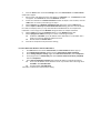
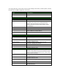
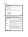
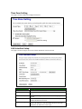
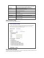
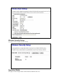
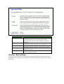
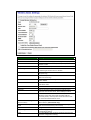
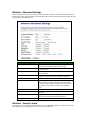
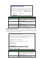
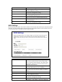
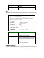
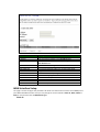
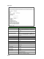
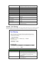
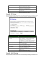
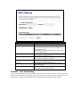
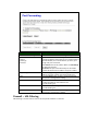
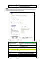
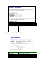
802.11 b/g/n
Wireless CPE
User Manual
Before Start to Configure
The WLAN Broadband Router is delivered with the following factory default parameters on the Ethernet
LAN interfaces.
Default IP Address: 192.168.1.254
Default IP subnet mask: 255.255.255.0
WEB login User Name: <empty> WEB login Password: <empty>
The device has three operation modes (Gateway/Bridge/WISP). The default IP addresses for the device
are 192.168.1.254, so you need to make sure the IP address of your PC is in the same subnet as the
device, such as 192.168.1.X.
It will take about 55 seconds to complete the boot up sequence after power on.
Prepare your PC to configure the WLAN Broadband Router
For OS of Microsoft Windows 95/ 98/ Me:
1.
2.
Click the Start button and select Settings, then click Control Panel. The
Control Panel window will appear.
Note: Windows Me users may not see the Network control panel. If so,
select View all Control Panel options on the left side of the window
Move mouse and double-click the right button on Network icon. The Network
window will appear.
Check the installed list of Network Components. If TCP/IP is not installed, click the Add
button to install it; otherwise go to step 6.
4.
Select Protocol in the Network Component Type dialog box and click Add button.
5.
Select TCP/IP in Microsoft of Select Network Protocol dialog box then click OK button
to install the TCP/IP protocol, it may need the Microsoft Windows CD to complete the
installation. Close and go back to Network dialog box after the TCP/IP installation.
6.
Select TCP/IP and click the properties button on the Network dialog box.
7.
Select Specify an IP address and type in values as following example.
IP Address: 192.168.1.1, any IP address within 192.168.1.1 to 192.168.1.253 is
good to connect the Wireless LAN Access Point.
IP Subnet Mask: 255.255.255.0
8.
Click OK and reboot your PC after completes the IP parameters setting.
3.
For OS of Microsoft Windows 2000, XP:
1.
Click the Start button and select Settings, then click Control Panel. The Control Panel
window will appear.
2.
Move mouse and double-click the right button on Network and Dial-up Connections
icon. Move mouse and double-click the Local Area Connection icon. The Local Area
Connection window will appear. Click Properties button in the Local Area Connection
window.
3.
Check the installed list of Network Components. If TCP/IP is not installed, click the Add
button to install it; otherwise go to step 6.
4.
Select Protocol in the Network Component Type dialog box and click Add button.
5.
Select TCP/IP in Microsoft of Select Network Protocol dialog box then click OK button
to install the TCP/IP protocol, it may need the Microsoft Windows CD to complete the
installation. Close and go back to Network dialog box after the TCP/IP installation.
6.
Select TCP/IP and click the properties button on the Network dialog box.
7.
Select Specify an IP address and type in values as following example.
IP Address: 192.168.1.1, any IP address within 192.168.1.1 to 192.168.1.253 is
good to connect the Wireless LAN Access Point.
IP Subnet Mask: 255.255.255.0
8.
Click OK to completes the IP parameters setting.
For OS of Microsoft Windows NT:
1.
Click the Start button and select Settings, then click Control Panel. The Control Panel
window will appear.
2.
Move mouse and double-click the right button on Network icon. The Network window
will appear. Click Protocol tab from the Network window.
3.
Check the installed list of Network Protocol window. If TCP/IP is not installed, click the
Add button to install it; otherwise go to step 6.
4.
Select Protocol in the Network Component Type dialog box and click Add button.
5.
Select TCP/IP in Microsoft of Select Network Protocol dialog box then click OK button
to install the TCP/IP protocol, it may need the Microsoft Windows CD to complete the
installation. Close and go back to Network dialog box after the TCP/IP installation.
6.
Select TCP/IP and click the properties button on the Network dialog box.
7.
Select Specify an IP address and type in values as following example.
IP Address: 192.168.1.1, any IP address within 192.168.1.1 to 192.168.1.253 is
good to connect the Wireless LAN Access Point.
IP Subnet Mask: 255.255.255.0
8.
Click OK to complete the IP parameters setting.
For OS of Microsoft Windows Vista and Windows 7
1.
Click Start Button and select Control Panel, the Control Panel windows pop up.
2.
From Network and Internet category choose View network status and tasks.
3.
Select Change adapter settings, right click Local Area Connection, select Properties
4.
From popup menu in Networking tab select Internet Protocol Version 4 (TCP/IPv4)
then click Properties.
5.
Check Use the following IP address then Specify IP address as following example.
Enter your IP Address; the IP Address can be any number within the range from
192.168.1.1 to 192.168.1.253.
IP Subnet Mask: 255.255.255.0
Click OK to complete the IP parameters setting.
This page shows the current status and some basic settings of the device, includes system, wireless,
Ethernet LAN and WAN configuration information.
Item
Description
Uptime
Firmware version
It shows the duration since WLAN Broad
It shows the firmware version of WLAN Broadband
Router.
Wireless Configuration
Mode
Band
SSID
Channel Number
Encryption
BSSID
Associated Clients
TCP/IP configuration
Attain IP Protocol
IP Address
Subnet Mask
Default Gateway
DHCP Server
MAC Address
WAN configuration
Attain IP Protocol
IP Address
Subnet Mask
Default Gateway
DNS1/DNS2/DNS3
MAC Address
It shows wireless operation mode
It shows wireless operation mode
It shows the SSID of this WLAN Broadband Router.
The SSID is the unique name of WLAN Broadband
Router and shared among its service area, so all
devices attempts to join the same wireless network
can identify it.
It shows the wireless channel connected currently.
It shows the status of encryption function.
It shows the BSSID address of the WLAN Broadband
Router. BSSID is a six-byte address.
It shows the number of connected clients (or stations,
PCs).
It shows type of connection.
It shows the IP address of LAN interfaces of WLAN
Broadband Router.
It shows the IP subnet mask of LAN interfaces of
WLAN Broadband Router.
It shows the default gateway setting for LAN
interfaces outgoing data packets.
It shows the DHCP server is enabled or not.
It shows the MAC address of LAN interfaces of
WLAN Broadband Router.
It shows how the WLAN Broadband Router gets the IP
address. The IP address can be set manually to a fixed
one or set dynamically by DHCP server or attain IP by
PPPoE / PPTP connection.
It shows the IP address of WAN interface of WLAN
Broadband Router.
It shows the IP subnet mask of WAN interface of
WLAN Broadband Router.
It shows the default gateway setting for WAN
interface outgoing data packets.
It shows the DNS server information.
It shows the MAC address of WAN interface of WLAN
Broadband Router.
Setup Wizard
This page guides you to configure wireless broadband router for first time
Operation Mode
This page followed by Setup Wizard page to define the operation mode.
Time Zone Setting
This page is used to enable and configure NTP client
LAN Interface Setup
This page is used to configure local area network IP address and subnet mask
Item
Description
IP Address
Subnet Mask
Fill in the address of LAN interfaces of this WLAN Access Point.
Fill in the subnet mask of LAN interfaces of this WLAN Access
Point.
Fill in the default gateway for LAN interfaces out going data
packets.
Click to select Disabled, Client or Server in different operation
mode of wireless Access Point.
Fill in the start IP address and end IP address to allocate a
range of IP addresses; client with DHCP function set will be
assigned an IP address from the range.
Default Gateway
DHCP
DHCP Client Range
Show Client
Static DHCP
Set Static DHCP
Domain Name
802.1d Spanning Tree
Clone MAC Address
Apply Changes
Reset
Click to open the active DHCP Client Table window that shows
the active clients with their assigned IP address, MAC address
and time expired information.[Server mode only]
Select enable or disable the Static DHCP function from
pull-down menu[Server mode only]
Manual setup Static DHCP IP address for specific MAC
address.[Server mode only]
Assign Domain Name and dispatch to DHCP clients. It is
optional field.
Select enable or disable the IEEE 802.1d Spanning Tree function
from pull-down menu.
Fill in the MAC address that is the MAC address to be cloned
Click the Apply Changes button to complete the new
configuration setting
Click the reset button to abort change and recover the previous
configuration setting.
WAN Interface Setup
This page is used to configure WAN access type
Wireless Basic Settings
This page is used to configure basic wireless parameters like Band, Mode, Network Type SSID, Channel
Number, Enable Mac Clone (Single Ethernet Client).
Wireless Security Setup
This page is used to configure wireless security
Operation Mode
This page is used to configure which mode wireless broadband router acts
Item
Description
Gateway
Traditional gateway configuration. It always connects internet
via ADSL/Cable Modem. LAN interface, WAN interface,
Wireless interface, NAT and Firewall modules are applied to
this mode
Each interface (LAN, WAN and Wireless) regards as bridge. NAT,
Firewall and all router’s functions are not supported
Switch Wireless interface to WAN port and all Ethernet ports in
bridge mode. Wireless interface can do all router’s functions
Click the Apply Changes button to complete the new
configuration setting.
Click the Reset button to abort change and recover the
previous configuration setting.
Bridge
Wireless ISP
Apply Changes
Reset
Wireless - Basic Settings
This page is used to configure the parameters for wireless LAN clients that may connect to your
Broadband Router. Here you may change wireless encryption settings as well as wireless network
parameters.
Item
Description
Disable Wireless LAN Interface
Band
Mode
Click on to disable the wireless LAN data transmission.
Click to select 2.4GHz(B) / 2.4GHz(G) /2.4GHz(B+G)
Click to select the WLAN AP / Client / WDS / AP+WDS
wireless mode.
Click to enable multiple AP.
While network is selected to be client. Click to select
network type infrastructure or Ad-Hoc
It is the wireless network name. The SSID can be
32 bytes long.
Select the operational bandwidth 20MHz or 40MHz
(802.11n band only)
Select the sideband with upper or lower for channel
width 40MHz.
Select the wireless communication channel from
pull-down menu.
Click to enable or disable the SSID broadcast function
Click to enable or disable WMM function
Select transmission data rate from pull-down menu.
Data rate can be auto select, 1M to 54Mbps or MCS.
Click the Show Active Clients button to open Active
Wireless Client Table that shows the MAC address,
transmit-packet, receive-packet and transmission-rate
for each associated wireless client.
Take Laptop NIC MAC address as wireless client
MAC address. [Client Mode only]
Click to enable Universal Repeater Mode. (Acting as AP
and client simultaneously in this mode).
Assign SSID when enables Universal Repeater Mode.
Click the Apply Changes button to complete the new
configuration setting.
Click the Reset button to abort change and recover the
previous configuration setting.
Multiple AP
Network Type
SSID
Channel width
Control Sideband
Channel Number
Broadcast SSID
WMM
Data Rate
Associated Clients
Enable Mac Clone (Single
Ethernet Client)
Enable Universal Repeater
Mode
SSID of Extended Interface
Apply Changes
Reset
Wireless - Advanced Settings
These settings are only for more technically advanced users who have a sufficient knowledge about
wireless LAN. These settings should not be changed unless you know what effect the changes will have
on your WLAN Broadband Router.
Item
Fragment Threshold
RTS Threshold
Beacon Interval
Preamble Type
IAPP
Protection
Aggregation
Short GI
WLAN Partition
RF Output power
Description
Set the data packet fragmentation threshold, value
can be written between 256 and 2346 bytes.
Set the RTS Threshold, value can be written between 0
and 2347 bytes.
Set the Beacon Interval, value can be written between
20 and 1024ms.
Click to select the Long Preamble or Short Preamble
support on the wireless data packet transmission.
Click to enable or disable the IAPP function.
Protection is for neighboring 802.11b wireless network.
Select disable to reduce the adverse affect of legacy
wireless network 802.11n performance. This option is
available only when 802.11 mode is set to 802.11n
only
Click to enable or disable aggregation function.
Click to enable or disable short Guard Intervals
function
Enabling WLAN Partition prevents associated wireless
clients from communicating with each other.
To adjust transmission power level.
Wireless - Security Setup
This page allows you setup the wireless security. Turn on WEP, WPA; WPA2 by using encryption keys
could prevent any unauthorized access to your wireless network.
Item
Select SSID
Encryption
Use 802.1x Authentication
Apply Changes
Reset
Description
Select SSID to be encrypted from multiple APs.
Select the encryption supported over wireless access.
The encryption method can be None, WEP, WPA(TKIP),
WPA2 or WPA2 Mixed
While Encryption is selected to be WEP. Click the
check box to enable IEEE 802.1x authentication
function.
Click the Apply Changes button to complete the new
configuration setting.
Click the Reset button to abort change and recover
the previous configuration setting.
Wireless - Access Control
If you enable wireless access control, only those clients whose wireless MAC addresses are in the access
control list will be able to connect to your Access Point. When this option is enabled, no wireless clients
will be able to connect if the list contains no entries.
Item
Description
Wireless Access Control Mode
Click the Disabled, Allow Listed or Deny Listed of drop
down menu choose wireless access control mode.
This is a security control function; only those clients
registered in the access control list can link to this
WLAN Broadband Router.
Fill in the MAC address of client to register this
WLAN Broadband Router access capability.
MAC Address
Comment
Apply Changes
Reset
Current Access Control List
Delete Selected
Delete All
Reset
Enter notes for the registered client.
Click the Apply Changes button to register the client
to new configuration setting.
Click the Reset button to abort change and recover
the previous configuration setting.
It shows the registered clients that are allowed to link
to this WLAN Broadband Router.
Click to delete the selected clients that will be access
right removed from this WLAN Broadband Router.
Click to delete all the registered clients from the
access allowed list.
Click the Reset button to abort change and recover
the previous configuration setting.
WDS Settings
Wireless Distribution System uses wireless media to communicate with other APs, like the Ethernet does.
To do this, you must set these APs in the same channel and set MAC address of other AP that you want
to communicate with in the table and then enable the WDS.
Item
Enable WDS
MAC Address
Data Rate
Comment
Apply Changes
Reset
Set Security
Description
Click the Disabled, Allow Listed or Deny Listed of drop
down menu choose wireless access control mode.
This is a security control function; only those clients
registered in the access control list can link to this
WLAN Broadband Router.
Fill in the MAC address of client to register this
WLAN Broadband Router access capability.
Select transmission data rate from pull down menu.
Data rate can be auto-selected, 1Mbps to 54Mbps or
MCS.
Fill in the comments for the registered client.
Click the Apply Changes button to register the client
to new configuration setting.
Click the Reset button to abort change and recover
the previous configuration setting.
Click button to configure wireless security like
WEP(64bits), WEP(128bits), WPA(TKIP), WPA2(AES)
Show Statistics
Delete Selected
Delete All
Reset
or None
It shows the TX, RX packets, rate statistics
Click to delete the selected clients that will be
removed from the wireless distribution system.
Click to delete all the registered APs from the wireless
distribution system allowed list.
Click the Reset button to abort change and recover
the previous configuration setting.
It shows the registered clients that are allowed to link to this WLAN Broadband Router.
WDS Security Setup
Requirement: Set [Wireless]->[Basic Settings]->[Mode]->AP+WDS
This page is used to configure the wireless security between APs.
WDS AP Table
This page is used to show WDS statistics
Item
MAC Address
Tx Packets
Tx Errors
Rx Packets
Tx Rate (Mbps)
Refresh
Close
Description
It shows the MAC Address within WDS.
It shows the statistic count of sent packets on the
wireless LAN interface.
It shows the statistic count of error sent packets on
the Wireless LAN interface.
It shows the statistic count of received packets on the
wireless LAN interface.
It shows the wireless link rate within WDS.
Click to refresh the statistic counters on the screen.
Click to close the current window.
Site Survey
This page is used to scan and connect nearby APs when operate at client mode.
Item
SSID
BSSID
Channel
Type
Encrypt
Description
It shows the SSID of AP.
It shows BSSID of AP.
It show the current channel of AP occupied.
It shows which type of connection to be connect,
infrastructure (AP) or ad-hoc.
It shows the encryption status.
Signal
Refresh
Connect
It shows signal strength (expressed in percentage) of
current AP.
Click the Refresh button to re-scan site survey on the
screen.
Click the Connect button to establish connection.
WPS
This page allows you to change the setting for WPS (Wi-Fi Protected Setup). Using this feature could let
your wireless client automatically synchronize its setting and connect to the Access Point in a minute
without any hassle.
Item
Disable WPS
WPS Status
Self-PIN Number
Push Button Configuration
Apply Changes
Reset
Client PIN Number
Description
Click on to disable the Wi-Fi Protected Setup function
Show WPS status is Configured or Unconfigured
Fill in the PIN Number of AP to register the wireless
distribution system access capability.
The Start PBC button provides tool to scan the
wireless network. If any Access Point or IBSS is found,
you could connect it automatically when client join
PBC mode.
Click the Apply Changes button to complete the new
configuration setting.
Click the Reset button to abort change and recover the
previous configuration setting.
Fill in the Client PIN Number from your Client sites.
LAN Interface Setup
This page is used to configure the parameters for local area network that connects to the LAN ports of
your WLAN Broadband Router. Here you may change the setting for IP address, subnet mask, DHCP, etc.
Item
IP Address
Subnet Mask
Default Gateway
DHCP
DHCP Client Range
Show Client
Static DHCP
Domain Name
802.1d Spanning Tree
Clone MAC Address
Apply Changes
Reset
Description
Fill in the IP address of LAN interfaces of this WLAN
Access Point.
Fill in the subnet mask of LAN interfaces of this WLAN
Access Point.
Fill in the default gateway for LAN interfaces out
going data packets.
Click to select Disabled, Client or Server in different
operation mode of wireless Access Point.
Fill in the start IP address and end IP address to
allocate a range of IP addresses; client with DHCP
function set will be assigned an IP address from the
range.
Click to open Active DHCP Client Table window that
shows current active clients with their assigned IP
address, MAC address and expire time information
[Server mode only]
Select to enable or disable Static DHCP from pull-down
menu [Server mode only]
Assign Domain Name and dispatch to DHCP clients. It
is optional field.
Select to enable or disable the IEEE 802.1d Spanning
Tree function from pull-down menu.
Fill in the MAC address that is the MAC address to be
cloned.
Click the Apply Changes button to complete the new
configuration setting.
Click the Reset button to abort change and recover
the previous configuration setting.
Static DHCP Setup
This page allows you reserve IP addresses, and assign the same IP address to the network device with the
specified MAC address any time it requests an IP address. This is almost the same as when a device has a
static IP address except that the device must still request an IP address from the DHCP server
Item
Description
Enable Static DHCP
IP Address
MAC Address
Click to enable Static DHCP
Enter the Static IP Address in the IP Address field
Enter the MAC address of the corresponding Client in the
MAC Address field
Take notes of the setting.
Click the Apply Changes button to complete the change
List mapping of static IP address to corresponding clients.
Assigned static IP address
MAC address of corresponding client
Notes of the mapping
Click on checkbox if you want to delete from the list.
Click to delete current selected from the list.
Delete all of the entries from the list.
Uncheck all of previous selections.
Comment
Apply Changes
Static DHCP List
IP Address
MAC address
Comment
Select
Delete Selected
Delete All
Reset
WAN Interface Setup
This page is used to configure the parameters for wide area network that connects to the WAN port of
your WLAN Broadband Router. Here you may change the access method to Static IP, DHCP, PPPoE or
PPTP by click the item value of WAN Access Type.
Static IP
Item
Static IP
IP Address
Subnet Mask
Default Gateway
MTU Size
DNS 1
DNS 2
DNS 3
Clone MAC Address
Enable uPNP
Enable IGMP Proxy
Enable Ping Access on WAN
Enable Web server Access on
WAN
Enable IPsec pass through on
VPN connection
Enable PPTP pass through on
VPN connection
Enable L2TP pass through on
VPN connection
Apply Changes
Reset
Description
Click to select Static IP support on WAN interface.
There are IP address, subnet mask and default
gateway settings need to be done
If you select the Static IP support on WAN interface, fill
in the IP address for it.
If you select the Static IP support on WAN
interface, fill in the subnet mask for it
If you select the Static IP support on WAN interface,
fill in the default gateway for WAN interface out going
data packets.
Fill in the mtu size of MTU Size. The default value is
1400
Enter the IP address of Domain Name Server 1.
Enter the IP address of Domain Name Server 2.
Enter the IP address of Domain Name Server 3.
Enter the MAC address that is the MAC address to be
cloned
Click the checkbox to enable uPNP function.
Click the checkbox to enable IGMP proxy
Click the checkbox to enable WAN IGMP response.
Click the checkbox to enable web configuration from
WAN side
Click the checkbox to enable IPSec packet pass
through
Click the checkbox to enable PPTP packet pass
through
Click the checkbox to enable L2TP packet pass
through
Click the Apply Changes button to complete the new
configuration setting.
Click the Reset button to abort change and recover
the previous configuration setting.
DHCP Client
Item
DHCP Client
Host Name
MTU Size
Attain DNS Automatically
Set DNS Manually
DNS 1
DNS 2
DNS 3
Clone MAC Address
Enable uPNP
Enable IGMP Proxy
Enable Ping Access on WAN
Enable Web server Access on
WAN
Enable IPsec pass through on
VPN connection
Enable PPTP pass through on
VPN connection
Enable L2TP pass through on
VPN connection
Apply Changes
Reset
PPPoE
Description
Click to select DHCP support on WAN interface for IP
address assigned automatically from a DHCP server.
Fill in the host name of Host Name. The default value
is empty
Fill in the mtu size of MTU Size. The default value is
1400
Click to select getting DNS address for DHCP support.
Please select Set DNS Manually if the DHCP support is
selected.
Click to select getting DNS address for DHCP support.
Fill in the IP address of Domain Name Server 1.
Fill in the IP address of Domain Name Server 2.
Fill in the IP address of Domain Name Server 3.
Fill in the MAC address that is the MAC address to be
cloned
Click the checkbox to enable uPNP function.
Click the checkbox to enable IGMP proxy
Click the checkbox to enable WAN IGMP response.
Click the checkbox to enable web configuration from
WAN side
Click the checkbox to enable IPSec packet pass
through
Click the checkbox to enable PPTP packet pass
through
Click the checkbox to enable L2TP packet pass
through
Click the Apply Changes button to complete the new
configuration setting.
Click the Reset button to abort change and recover
the previous configuration setting.
Item
PPPoE
User Name
Password
Service Name
Connection Type
Idle Time
MTU Size
Description
Click to select PPPoE support on WAN interface.
There are user name, password, connection type and
idle time settings need to be done.
If you select the PPPoE support on WAN interface, fill
in the user name and password to login the PPPoE
server.
If you select the PPPoE support on WAN interface, fill
in the user name and password to login the PPPoE
server.
Fill in the service name of Service Name. The default
value is empty.
Select the connection type from pull-down menu.
There are Continuous, Connect on Demand and
Manual three types to select. Continuous connection
type means to setup the connection through PPPoE
protocol whenever this WLAN Broadband Router is
powered on.
Connect on Demand connection type means to setup
the connection through PPPoE protocol whenever you
send the data packets out through the WAN interface;
there are a watchdog implemented to close the PPPoE
connection while there are no data sent out longer
than the idle time set. Manual connection type means
to setup the connection through the PPPoE protocol
by clicking the Connect button manually, and clicking
the Disconnect button manually.
If you select the PPPoE and Connect on Demand
connection type, fill in the idle time for
auto-disconnect function. Value can be between 1 and
1000 minutes.
Fill in the mtu size of MTU Size. The default value is
1400
Attain DNS Automatically
Set DNS Manually
DNS 1
DNS 2
DNS 3
Clone MAC Address
Enable uPNP
Enable IGMP Proxy
Enable Ping Access on WAN
Enable Web server Access on
WAN
Enable IPsec pass through on
VPN connection
Enable PPTP pass through on
VPN connection
Enable L2TP pass through on
VPN connection
Apply Changes
Reset
Click to select getting DNS address for DHCP support.
Please select Set DNS Manually if the DHCP support is
selected.
Click to select getting DNS address for DHCP support.
Fill in the IP address of Domain Name Server 1.
Fill in the IP address of Domain Name Server 2.
Fill in the IP address of Domain Name Server 3.
Fill in the MAC address that is the MAC address to be
cloned
Click the checkbox to enable uPNP function.
Click the checkbox to enable IGMP proxy
Click the checkbox to enable WAN IGMP response.
Click the checkbox to enable web configuration from
WAN side
Click the checkbox to enable IPSec packet pass
through
Click the checkbox to enable PPTP packet pass
through
Click the checkbox to enable L2TP packet pass
through
Click the Apply Changes button to complete the new
configuration setting.
Click the Reset button to abort change and recover
the previous configuration setting.
PPTP
Item
PPTP
IP Address
Subnet Mask
Server IP Address
User Name
Password
Connection Type
Description
Allow user to make a tunnel with remote site directly
to secure the data transmission among the
connection. User can use embedded PPTP client
supported by this router to make a VPN connection.
If you select the PPTP support on WAN interface, fill in
the IP address for it.
If you select the PPTP support on WAN interface, fill in
the subnet mask for it.
Enter the IP address of the PPTP Server.
If you select the PPTP support on WAN interface, fill in
the user name and password to login the PPTP server.
If you select the PPTP support on WAN interface, fill in
the user name and password to login the PPTP server.
Select the connection type from pull-down menu.
There are Continuous, Connect on Demand and
Idle Time
MTU Size
Request MPPE Encryption
Request MPPC Compression
Attain DNS Automatically
Set DNS Manually
DNS 1
DNS 2
DNS 3
Clone MAC Address
Enable uPNP
Enable IGMP Proxy
Enable Ping Access on WAN
Enable Web server Access on
WAN
Enable IPsec pass through on
VPN connection
Enable PPTP pass through on
VPN connection
Enable L2TP pass through on
VPN connection
Apply Changes
Reset
Manual three types to select. Continuous connection
type means to setup the connection through PPPoE
protocol whenever this WLAN Broadband Router is
powered on.
Connect on Demand connection type means to setup
the connection through PPPoE protocol whenever you
send the data packets out through the WAN interface;
there are a watchdog implemented to close the PPPoE
connection while there are no data sent out longer
than the idle time set. Manual connection type means
to setup the connection through the PPPoE protocol
by clicking the Connect button manually, and clicking
the Disconnect button manually.
The amount of time of inactivity before the device will
disconnect your PPTP session.
Fill in the mtu size of MTU Size. The default value is
1400
Click the checkbox to enable request MPPE
encryption.
Click the checkbox to enable request MPPC
compression.
Click to select getting DNS address for DHCP support.
Please select Set DNS Manually if the DHCP support is
selected.
Click to select getting DNS address for DHCP support.
Fill in the IP address of Domain Name Server 1.
Fill in the IP address of Domain Name Server 2.
Fill in the IP address of Domain Name Server 3.
Fill in the MAC address that is the MAC address to be
cloned
Click the checkbox to enable uPNP function.
Click the checkbox to enable IGMP proxy
Click the checkbox to enable WAN IGMP response.
Click the checkbox to enable web configuration from
WAN side
Click the checkbox to enable IPSec packet pass
through
Click the checkbox to enable PPTP packet pass
through
Click the checkbox to enable L2TP packet pass
through
Click the Apply Changes button to complete the new
configuration setting.
Click the Reset button to abort change and recover
the previous configuration setting.
L2tP
Use Layer 2 Tunneling Protocol (L2TP) if your ISP uses an L2TP connection. Your ISP will provide you with a
username and password.
Item
L2TP
IP Address
Subnet Mask
Server IP Address
User Name
Password
Connection Type
Idle Time
Description
Allow user to make a tunnel with remote site directly
to secure the data transmission among the
connection. User can use embedded PPTP client
supported by this router to make a VPN connection.
Enter L2TP IP address supplied by your ISP (Static only).
Enter subnet mask.
Enter L2TP Server IP address provided by your ISP.
Enter L2TP service username provided by your ISP.
Enter L2TP service password provided by your ISP.
Select the connection type from pull-down menu.
There are Continuous, Connect on Demand and
Manual three types to select. Continuous connection
type means to setup the connection through L2TP
protocol whenever this WLAN Broadband Router is
powered on.
Connect on Demand connection type means to setup
the connection through L2TP protocol whenever you
send the data packets out through the WAN interface;
there are a watchdog implemented to close the L2TP
connection while there are no data sent out longer
than the idle time set. Manual connection type means
to setup the connection through the L2TP protocol by
clicking the Connect button manually, and clicking the
Disconnect button manually.
The amount of time of inactivity before the device will
disconnect your L2TP session.
MTU Size
Attain DNS Automatically
Set DNS Manually
DNS 1
DNS 2
DNS 3
Clone MAC Address
Enable uPNP
Enable IGMP Proxy
Enable Ping Access on WAN
Enable Web server Access on
WAN
Enable IPsec pass through on
VPN connection
Enable PPTP pass through on
VPN connection
Enable L2TP pass through on
VPN connection
Apply Changes
Change the MTU size that your ISP provided. The
default value is 1400 and range is 1400 to 1460 bytes.
Click to get DNS IP address automatically.
Enter DNS IP address provided by your ISP manually.
Enter the IP address of Domain Name Server 1.
Enter the IP address of Domain Name Server 2.
Enter the IP address of Domain Name Server 3.
Clone MAC address of your computer.
Click the checkbox to enable uPNP function.
Click the checkbox to enable IGMP proxy
Click the checkbox to enable WAN IGMP response.
Click the checkbox to enable web configuration from
WAN side
Click the checkbox to enable IPSec packet pass
through
Click the checkbox to enable PPTP packet pass
through
Click the checkbox to enable L2TP packet pass
through
Click the Apply Changes button to complete the new
configuration setting.
Firewall - Port Filtering
Entries in this table are used to restrict certain types of data packets from your local network to Internet
through the Gateway. Use of such filters can be helpful in securing or restricting your local network.
Item
Enable Port Filtering
Port Range Protocol, Comments
Apply Changes
Description
Click to enable the port filtering security function.
To restrict data transmission from the local network
on certain ports, fill in the range of Start-port and
end-port, and the protocol, also put your comments
on it. The Protocol can be TCP, UDP or Both.
Comments let you know about whys to restrict data
from the ports.
Click the Apply Changes button to register the ports
to port filtering list.
Reset
Delete Selected
Delete All
Reset
Click the Reset button to abort change and recover
the previous configuration setting.
Click to delete the selected port range that will be
removed from the port-filtering list.
Click to delete all the registered entries from the
port-filtering list.
Click the Reset button to abort change and recover
the previous configuration setting.
Firewall - IP Filtering
Entries in this table are used to restrict certain types of data packets from your local network to Internet
through the Gateway. Use of such filters can be helpful in securing or restricting your local network.
Item
Enable IP Filtering
Local IP Address; Protocol;
Comments
Apply Changes
Reset
Delete Selected
Delete All
Reset
Description
Click to enable the IP filtering security function.
To restrict data transmission from local network on
certain IP addresses, fill in the IP address and the
protocol; also put your comments on it.
The Protocol can be TCP, UDP or Both. Comments let
you know about whys to restrict data from the IP
address.
Click the Apply Changes button to register the IP
address to IP filtering list.
Click the Reset button to abort change and recover
the previous configuration setting.
Click to delete the selected IP address that will be
removed from the IP-filtering list.
Click to delete all the registered entries from the
IP-filtering list.
Click the Reset button to abort change and recover
the previous configuration setting.
Firewall - MAC Filtering
Entries in this table are used to restrict certain types of data packets from your local network to Internet
through the Gateway. Use of such filters can be helpful in securing or restricting your local network.
Item
Enable MAC Filtering
MAC Address; Comments
Apply Changes
Reset
Delete Selected
Delete All
Reset
Description
Click to enable the MAC filtering security function.
To restrict data transmission from local network on
certain MAC addresses, fill in the MAC address and
your comments on it.
Comments let you know about whys to restrict data
from the MAC address.
Click the Apply Changes button to register the
MAC address to MAC filtering list.
Click the Reset button to abort change and recover
the previous configuration setting.
Click to delete the selected MAC address that will be
removed from the MAC-filtering list.
Click to delete all the registered entries from the
MAC-filtering list.
Click the Reset button to abort change and recover
the previous configuration setting.
Firewall - Port Forwarding
Entries in this table allow you to automatically redirect common network services to a specific machine
behind the NAT firewall. These settings are only necessary if you wish to host some sort of server like a
web server or mail server on the private local network behind your Gateway's NAT firewall.
Item
Enable Port Forwarding
Local IP Address
Protocol
Port Range
Comment
Apply Changes
Reset
Delete Selected
Delete All
Reset
Description
Click to enable the Port Forwarding security function.
To forward data packets coming from WAN to a
specific IP address that hosted in local network behind
the NAT firewall, fill in the IP address, protocol, port
range and your comments.
The Protocol can be TCP, UDP or Both. The Port Range
for data transmission.
Comments let you know about whys to allow data
packets forward to the IP address and port number.
Click the Apply Changes button to register the IP
address and port number to Port forwarding list.
Click the Reset button to abort change and recover
the previous configuration setting.
Click to delete the selected IP address and port
number that will be removed from the
port-forwarding list.
Click to delete all the registered entries from the
port-forwarding list.
Click the Reset button to abort change and recover
the previous configuration setting.
Firewall – URL Filtering
URL Filtering is used to restrict users to access specific websites in internet.
Item
Enable URL Filtering
URL Address
Apply Changes
Reset
Delete Selected
Delete All
Reset
Description
Click to enable the URL Filtering function.
Add one URL address.
Click the Apply Changes button to save settings.
Click the Reset button to abort change and recover
the previous configuration setting.
Click to delete the selected URL address that will be
removed from the URL Filtering list.
Click to delete all the registered entries from the URL
Filtering list
Click the Reset button to abort change and recover
the previous configuration setting.
Firewall - DMZ
A Demilitarized Zone is used to provide Internet services without sacrificing unauthorized access to its
local private network. Typically, the DMZ host contains devices accessible to Internet traffic, such as Web
(HTTP) servers, FTP servers, SMTP (e-mail) servers and DNS servers.
Item
Enable DMZ
DMZ Host IP Address
Apply Changes
Description
Click to enable the DMZ function.
To support DMZ in your firewall design, fill in the IP
address of DMZ host that can be access from the WAN
interface.
Click the Apply Changes button to register the IP
address of DMZ host.
Reset
Click the Reset button to abort change and recover
the previous configuration setting.
QoS
Entries in this table improve your online gaming experience by ensuring that your game traffic is
prioritized over other network traffic, such as FTP or Web
Item
Enable QoS
Automatic Uplink Speed
Manually Uplink Speed [Kbps]
Automatic downlink Speed
[Kbps]
QoS Rule Setting
Address Type
Local IP Address
MAC Address
Mode
Uplink Bandwidth
Downlink Bandwidth
Comment
Apply Changes
Description
Click to enable the QoS function.
Click checkbox to enable uplink automatic bandwidth
control.
Enter uplink speed in Kbps to constrain maximum
uplink bandwidth capacity.
Click checkbox to enable downlink automatic
bandwidth control.
Select IP address or MAC address
Enter local IP address range
Enter MAC address you are going to control.
Select band width control type Guaranteed minimum
bandwidth or Restricted maximum bandwidth.
Enter uplink bandwidth in Kbps
Enter downlink bandwidth in Kbps
Give a definition to the setting
Click the Apply Changes button to save the settings
Click the Reset button to abort change and recover
the previous configuration setting.
Reset
Current QoS Rule Table
Local IP Address
MAC Address
Mode
List LAN IP address that is controlled.
List MAC address that is controlled.
List control type that is controlled. Guaranteed
minimum bandwidth or Restricted maximum
bandwidth.
List uplink bandwidth
List Download bandwidth
Definition of the setting
Click to select rule for further action.
Delete selected rules.
Delete all rules listed on table.
Click the Reset button to abort change and recover
the previous configuration setting.
Uplink Bandwidth
Download Bandwidth
Comment
Select
Delete Selected
Delete All
Reset
Management - Statistics
This page shows the packet counters for transmission and reception regarding to wireless, Ethernet LAN
and Ethernet WAN networks.
Item
Wireless LAN
Sent Packets
Received Packets
Ethernet LAN
Sent Packets
Received Packets
Ethernet WAN
Sent Packets
Received Packets
Refresh
Description
It shows the statistic count of sent packets on the wireless LAN
interface.
It shows the statistic count of received packets on the wireless
LAN interface.
It shows the statistic count of sent packets on the Ethernet
LAN interface.
It shows the statistic count of received packets on the
Ethernet LAN interface.
It shows the statistic count of sent packets on the Ethernet
WAN interface.
It shows the statistic count of received packets on the
Ethernet WAN interface.
Click the refresh the statistic counters on the screen.
Management - DDNS
This page is used to configure Dynamic DNS service to have DNS with dynamic IP address.
Item
Enable DDNS
Service Provider
Domain Name
User Name/Email
Password/Key
Apply Change
Reset
Description
Click the checkbox to enable DDNS service.
Click the drop down menu to pick up the right provider.
To configure Domain Name.
Configure User Name, Email.
Configure Password, Key.
Click the Apply Changes button to save the enable DDNS
service.
Click the Reset button to abort change and recover the
previous configuration setting.
Management - Time Zone Setting
This page is used to configure NTP client to get current time.
Item
Current Time
Time Zone Select
Enable NTP client update
NTP Server
Apply Change
Description
It shows the current time.
Click the time zone in your country.
Click the checkbox to enable NTP client update. R
Click select default or input NTP server IP address.
Click the Apply Changes button to save and enable NTP
Reset
Refresh
client service.
Click the Reset button to abort change and recover the
previous configuration setting.
Click the refresh the current time shown on the screen.
Management – Denial-of-Service
This page is used to enable and setup protection to prevent attack by hacker’s program. It provides
more security for users.
Item
Enable DoS Prevention
Whole System Flood/
Per-Source IP Flood
Select ALL
Clear ALL
Apply Changes
Description
Click the checkbox to enable DoS prevention.
Enable and setup prevention in details.
Click the checkbox to enable all prevention items.
Click the checkbox to disable all prevention items
Click the Apply Changes button to save above settings.
Management - Log
This page is used to configure the remote log server and shown the current log.
Item
Enable Log
System all
Wireless
DoS
Enable Remote Log
Log Server IP Address
Apply Changes
Refresh
Clear
Description
Click the checkbox to enable log.
Show all log of wireless broadband router
Only show wireless log
Only show Denial-of-Service log
Click the checkbox to enable remote log service.
Input the remote log IP address
Click the Apply Changes button to save above settings.
Click the refresh the log shown on the screen.
Clear log display screen
Management - Upgrade Firmware
This page allows you upgrade the Access Point firmware to new version. Please note, do not power off
the device during the upload because it may crash the system.
Item
Select File
Upload
Reset
Description
Click the Browse button to select the new version of web
firmware image file.
Click the Upload button to update the selected web
firmware image to the WLAN Broadband Router.
Click the Reset button to abort change and recover the
previous configuration setting.
Management Save/ Reload Settings
This page allows you save current settings to a file or reload the settings from the file that was saved
previously. Besides, you could reset the current configuration to factory default.
Item
Description
Save Settings to File
Click the Save button to download the configuration
parameters to your personal computer.
Click the Browse button to select the configuration
files then click the Upload button to update the selected
configuration to the WLAN Broadband Router.
Click the Reset button to reset the configuration
parameter to factory defaults.
Load Settings from File
Reset Settings to Default
Management - Password Setup
This page is used to set the account to access the web server of Access Point. Empty user name and
password will disable the protection.
Item
User Name
New Password
Confirmed Password
Apply Changes
Reset
Description
Fill in the user name for web management login control.
Fill in the password for web management login control.
Because the password input is invisible, so please fill in
the password again for confirmation purpose.
Clear the User Name and Password fields to empty,
means to apply no web management login control. Click
the Apply Changes button to complete the new
configuration setting.
Click the Reset button to abort change and recover the
previous configuration setting.