1
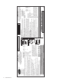
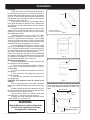
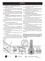
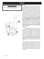
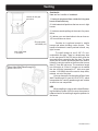
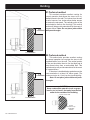
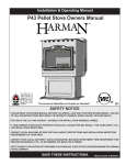
Installation & Operating Manual
P68 Pellet Stove Owners Manual
R7
“Ce manuel est disponible en Français sur demande”
SAFETY NOTICE
Please read this entire manual before you install and use your new room heater. Failure
to follow instructions may result in property damage, bodily injury, or even death.
FOR USE IN THE U.S. AND CANADA. SUITABLE FOR INSTALLATION IN MOBILE HOMES.
IF THIS HARMAN STOVE IS NOT PROPERLY INSTALLED, A HOUSE FIRE MAY RESULT. FOR YOUR SAFETY, FOLLOW INSTALLATION DIRECTIONS.
CONTACT LOCAL BUILDING OR FIRE OFFICIALS ABOUT RESTRICTIONS AND INSTALLATION INSPECTION
REQUIREMENTS IN YOUR AREA.
Contact your local authority (such as municipal building department, fire department, fire
prevention bureau, etc.) to determine the need for a permit.
Cette guide d'utilisation est disponible en francais. Chez votre concessionnaire de Harman
HOME HEATING.
R1
save these instructions.
Item # 3-90-00688
P68 Pellet Stove
OMNI-Test Laboratories, Inc.
Portland
Oregon USA
MODEL: "P68"
2" / 5 cm
0" / 0 cm
6" / 15 cm
2"
12"
9"
13"
WITH
SIDE SHIELDS
2"
20"
WITHOUT
SIDE SHIELDS
Ser# -
DO NOT REMOVE THIS LABEL / NE PAS ENLEVER CETTE ÉTIQUETTE
MADE IN USA / Fabriqué aux É.-U.
This model is exempt from EPA certification under 40 CFR 60.531 by definition [Wood Heater (A) "Air-to-Fuel Ratio"]
US ENVIRONMENTAL PROTECTION AGENCY
13"
33cm
6" - 15cm
2" 5cm
0"
25" Wide x 33" Deep
63.5cm Wide x 84cm Deep
2" 5cm
8cm min
3"min
PROTECTION DE SOL
FLOOR PROTECTION
13"
33cm
WITHOUT SIDE SHIELDS
Sans Écrans Latéraux
20"51cm
WITHOUT SIDE SHIELDS
Sans Écrans Latéraux
2"-5cm
3"min
Use a non-combustible floor protector extending
under the unit and to the sides, front, and back of unit
as shown in Floor Protection Diagram. Measure front
distance from the surface of the glass door.
Recommended: Non-combustible floor protection
extending beneath any horizontal sections of
venting, including the "T" on the back when venting vertically.
Sides
Back
Front
FLOOR PROTECTION
Back Wall To Appliance
Side Wall To Appliance
Corner Installation
Walls To Appliance
MINIMUM CLEARANCES
TO COMBUSTIBLES:
Room Heater Pellet Fuel Burning
Also for use in Mobile Homes.
This pellet burning appliance has been tested and
listed for use in Manufactured Homes in accordance
with OAR 814-23-900 through 814-23-909
"PREVENT HOUSE FIRES"
Install and use only in accordance with manufacturer's installation and operation
instructions. Contact local building or fire officials about restrictions and inspection in your area.
WARNING FOR MANUFACTURED HOMES: Do not install appliance in a sleeping
room. An outside combustion air inlet must be provided. The structural integrity of
the manufactured home floor, ceiling and walls must be maintained.
Refer to manufacturer's instructions and local codes for precautions required for
passing chimney through a combustible wall or ceiling. Inspect and clean exhaust
venting system frequently in accordance with manufacturer's instructions.
Use a 3" or 4" diameter type "L" or "PL" venting system.
Do not connect this unit to a chimney flue servicing another appliance.
FOR USE WITH PELLETIZED WOOD FUEL ONLY
Input Rating Max: 8 lb. fuel/hr.
U.S. Electrical Rating: 115 VAC, 60 Hz, Start 4.1 AMPS, Run 1.1 AMPS
European Electrical Rating: 240 VAC, 60 Hz, Start 2.0 AMPS, Run 1.1 AMPS
Route power cord away from unit.
DANGER: Risk of electrical shock. Disconnect power supply before servicing.
For further instruction, refer to owner's manual.
Replace glass only with 5mm ceramic available from your dealer.
Keep viewing and ash removal doors tightly closed during operation.
Report #/ Raport # 135-S-13-2
Tested to / Testé à:
ASTM E1509, ULC-S627-00,
and ULC-C1482-M1990
Tested and
Listed By
BAR CODE LABEL
23cm
Avec
Écrans
Latéraux
5cm
30.5cm
P.N. 3-90-06806
Fabriqué par: Harman Home Heating 352 Mountain House Road, Halifax PA 17032
Date of Manufacture / Date de fabrication:
2008 2009 2010 JAN FEB MAR APR MAY JUN JUL AUG SEP OCT NOV DEC
IGN
Agence Américaine pour la Protection de l'Environnement
Ce modéle est dispensé par EPA certification d'aprés 40 CFR 60.531 par dèfinition [Appareil á bois (A) << Ratio air/combustible>>]
Côtés
5 cm
Derriére
0 cm
Devant
15 cm
Utiliser une protection de sol lncombustible dépassant de l'appareil sur les côtés, l'arrière et le devant
comme indiqué sur le schéma. La mesure doit étre
prise á partir de la vitre frontale. ll est recommandé
que la protection de sol s'entende au dessous du
tuyau de fumée dans le cas d'une sortie horizontale
directe.
PROTECTION DE SOL
DISTANCES MINIMALES DE
SECURITE:
Sans
Écrans
Latéraux
Mur arriére - Poéle
5cm
Mur lntéral - Poéle
51cm
Installation en angle
Mur- Angle Poéle diagonale 33cm
Tests réalisés par OMNI
TEST LABORATORIES, Inc.
Report № 135-S-13-2
Modéle: "P68"
Appareil de chauffage à granulés de bois Utilisable dans des
mobile homes. Cet appareil de chauffage à granulés a été essayé
et homologué pour les maisons préfabriquées, conformément aux
normes 814-23-900 à 814-23-909 de l'OAR.
"PREVENTION DES INCENDIES"
Respecter scrupuleusement les instructions du constructeur pour l'installation et les
consignes de fonctionnement. Respecter les règles de sécuritè en vigueur dans votre
région.
AVERTISSEMENT POUR MOBILE HOMES: Ne pas installer dans une chambre. ll est
imperatif de prévoir une prise d'alr extérieur. L'intégrité structurale du plancher, du plafond
et des murs doit étre strictement préservée.
Se reporter aux instructions du fabricant et aux réglementations spécifiques locales
concernant les précautions requises lors de la traversée d'un mur ou d'un plafond.
Contróler et nettoyer fréquemment tout le systeme d'evacuation des fumées conformément aux recommandations du constructeur. Utiliser des tuyaux <<Spécial granulés>>
de Ø76 mm ou 102 mm. Ne pas raccorder ce poéle à un conduit de cheminée déjà
utilisé pour un autre appareil.
FONCTIONNE EXCLUSIVEMENT AVEC DES GRANULES DE BOIS.
ASTM E1509-ULC-C1482-M1990
Appareil de chauffage à granulé type (UM) 84-HUD. Consommation maximum: 3.63 kg/h.
U.S. Electrical Rating: 115 VAC, 60 Hz, Start 4.1 AMPS, Run 1.1 AMPS
Caractéristiques électriques: 240 VAC, 60 Hz-Intensité au démarrage 2.0A -Intensité
fonctionnement normal 1.1A. Tenir le cordon d'alimentation à l'écart du poèle.
DANGER: Risque d'électrocution. Débrancher l'appareil avant toute intervention.
Ne remplacer la vitre qu'avec une vitre céramique 5mm de méme qualité disponible
auprès de votre revendeur.
Pour une information plus compléte, se reporter à la notice d'utilisation. Tenir la porte
hermétiquement close durant fonctionnement.
Harman P68 Pellet Stove
Label measures: 4-3/8" high X 10-3/4"wide
8cm min
Introduction
The Award-Winning P68 Pellet Stove has the widest BTU range available, giving you 0 to 68,000 BTU
when you need it, automatically. The only thing you need to do is set your desired room temperature and
fill the hopper. With the P68 you will notice even heat throughout your home and a level of convenience
you never thought possible.
The P68 epitomizes the capability of Harman Pellet Stoves, taking advantage of Harman’s 20 years
of pellet stove design, technology and manufacturing. This 68,000 BTU stove has the highest output,
smartest controls, widest heating range, and minimal maintenance. The P68’s huge output is managed by
a microprocessor that senses the room temperature and the fire temperature with tiny thermister probes
and then determines the best feed rate. This improved and smarter control also has a diagnostic port for
connecting an external display showing live working data for easier troubleshooting.
The platinum combination is Harman’s Patented Feeder & Burn Pot, and ESP Control which have been
developed to their highest state. These features work together to allow amazing heat output with different
fuel quality, ash content and moisture.
Table of Contents
Important Notes / Safety Concerns
4
Installation
5
Venting
7
Automatic Operation
14
Serial #:
Manual Operation
17
This label is located on the back of the unit.
Harman
P68
Pellet
StoveNumber for future reference.
Please
copy
the
Serial
ESP Control
19
Label measures: 4-3/8" high X 10-3/4"wide
MODEL: "P68"
Tested and
Listed By
Portland
Oregon USA
OMNI-Test Laboratories, Inc.
Report #/ Raport # 135-S-13-2
Tested to / Testé à:
ASTM E1509, ULC-S627-00,
Room Heater Pellet Fuel Burning
Also for use in Mobile Homes.
This pellet burning appliance has been tested and
listed for use in Manufactured Homes in accordance
with OAR 814-23-900 through 814-23-909
Ser# -
20"51cm
WITHOUT SIDE SHIELDS
Sans Écrans Latéraux
8cm min
3"min
8cm min
13"
33cm
3"min
MINIMUM CLEARANCES
and ULC-C1482-M1990
WITH
WITHOUT
TO COMBUSTIBLES:
SIDE SHIELDS SIDE SHIELDS
"PREVENT HOUSE FIRES"
2"
2"
Install and use only in accordance with manufacturer's installation and operation Back Wall To Appliance
20"
12"
instructions. Contact local building or fire officials about restrictions and inspec- Side Wall To Appliance
tion in your area.
Corner Installation
WARNING FOR MANUFACTURED HOMES: Do not install appliance in a sleeping Walls To Appliance
13"
9"
room. An outside combustion air inlet must be provided. The structural integrity of
FLOOR PROTECTION
the manufactured home floor, ceiling and walls must be maintained.
Sides
2" / 5 cm
Refer to manufacturer's instructions and local codes for precautions required for Back
0" / 0 cm
passing chimney through a combustible wall or ceiling. Inspect and clean exhaust Front
6" / 15 cm
venting system frequently in accordance with manufacturer's instructions.
Use a non-combustible floor protector extending
Use a 3" or 4" diameter type "L" or "PL" venting system.
under the unit and to the sides, front, and back of unit
Do not connect this unit to a chimney flue servicing another appliance.
as shown in Floor Protection Diagram. Measure front
FOR USE WITH PELLETIZED WOOD FUEL ONLY
distance from the surface of the glass door.
Input Rating Max: 8 lb. fuel/hr.
Recommended: Non-combustible floor protection
U.S. Electrical Rating: 115 VAC, 60 Hz, Start 4.1 AMPS, Run 1.1 AMPS
extending beneath any horizontal sections of
European Electrical Rating: 240 VAC, 60 Hz, Start 2.0 AMPS, Run 1.1 AMPS
venting, including the "T" on the back when ventRoute power cord away from unit.
ing vertically.
DANGER: Risk of electrical shock. Disconnect power supply before servicing.
For further instruction, refer to owner's manual.
Replace glass only with 5mm ceramic available from your dealer.
Keep viewing and ash removal doors tightly closed during operation.
BAR CODE LABEL
WITHOUT SIDE SHIELDS
Sans Écrans Latéraux
2"-5cm
13"
33cm
PROTECTION DE SOL
FLOOR PROTECTION
0"
2" 5cm
2" 5cm
6" - 15cm
25" Wide x 33" Deep
63.5cm Wide x 84cm Deep
PROTECTION DE SOL
Low Draft Voltage Adjustment20
Room Sensor21
Avec
Écrans
Latéraux
5cm
30.5cm
23cm
Côtés
5 cm
Derriére
0 cm
Devant
15 cm
Utiliser une protection de sol lncombustible dépassant de l'appareil sur les côtés, l'arrière et le devant
comme indiqué sur le schéma. La mesure doit étre
prise á partir de la vitre frontale. ll est recommandé
que la protection de sol s'entende au dessous du
tuyau de fumée dans le cas d'une sortie horizontale
directe.
Maintenance22
Trouble Shooting27
Date of Manufacture / Date de fabrication:
2008 2009 2010 JAN FEB MAR APR MAY JUN JUL AUG SEP OCT NOV DEC
This model is exempt from EPA certification under 40 CFR 60.531 by definition [Wood Heater (A) "Air-to-Fuel Ratio"]
MADE IN USA / Fabriqué aux É.-U.
Tests réalisés par OMNI
TEST LABORATORIES, Inc.
Report № 135-S-13-2
DISTANCES MINIMALES DE
SECURITE:
Sans
Écrans
Latéraux
Mur arriére - Poéle
5cm
Mur lntéral - Poéle
51cm
Installation en angle
Mur- Angle Poéle diagonale 33cm
Agence Américaine pour la Protection de l'Environnement
Ce modéle est dispensé par EPA certification d'aprés 40 CFR 60.531 par dèfinition [Appareil á bois (A) << Ratio air/combustible>>]
US ENVIRONMENTAL PROTECTION AGENCY
DO NOT REMOVE THIS LABEL / NE PAS ENLEVER CETTE ÉTIQUETTE
Modéle: "P68"
Appareil de chauffage à granulés de bois Utilisable dans des
mobile homes. Cet appareil de chauffage à granulés a été essayé
et homologué pour les maisons préfabriquées, conformément aux
normes 814-23-900 à 814-23-909 de l'OAR.
"PREVENTION DES INCENDIES"
Respecter scrupuleusement les instructions du constructeur pour l'installation et les
consignes de fonctionnement. Respecter les règles de sécuritè en vigueur dans votre
région.
AVERTISSEMENT POUR MOBILE HOMES: Ne pas installer dans une chambre. ll est
imperatif de prévoir une prise d'alr extérieur. L'intégrité structurale du plancher, du plafond
et des murs doit étre strictement préservée.
Se reporter aux instructions du fabricant et aux réglementations spécifiques locales
concernant les précautions requises lors de la traversée d'un mur ou d'un plafond.
Contróler et nettoyer fréquemment tout le systeme d'evacuation des fumées conformément aux recommandations du constructeur. Utiliser des tuyaux <<Spécial granulés>>
de Ø76 mm ou 102 mm. Ne pas raccorder ce poéle à un conduit de cheminée déjà
utilisé pour un autre appareil.
FONCTIONNE EXCLUSIVEMENT AVEC DES GRANULES DE BOIS.
ASTM E1509-ULC-C1482-M1990
Appareil de chauffage à granulé type (UM) 84-HUD. Consommation maximum: 3.63 kg/h.
U.S. Electrical Rating: 115 VAC, 60 Hz, Start 4.1 AMPS, Run 1.1 AMPS
Caractéristiques électriques: 240 VAC, 60 Hz-Intensité au démarrage 2.0A -Intensité
fonctionnement normal 1.1A. Tenir le cordon d'alimentation à l'écart du poèle.
DANGER: Risque d'électrocution. Débrancher l'appareil avant toute intervention.
Ne remplacer la vitre qu'avec une vitre céramique 5mm de méme qualité disponible
auprès de votre revendeur.
Pour une information plus compléte, se reporter à la notice d'utilisation. Tenir la porte
hermétiquement close durant fonctionnement.
Fabriqué par: Harman Home Heating 352 Mountain House Road, Halifax PA 17032
P.N. 3-90-06806
IGN
Please read this entire manual before you install
and use your new room heater. Failure to follow instructions may result in property damage,
bodily injury, or even death.
Feeder Parts28
Specifications
29
Options30
Wiring Diagram31
Parts List32
352 Mountain House Road
Halifax, PA 17032
Warranty33
P68 Pellet Stove IMPORTANT NOTES
DO NOT INSTALL A FLUE DAMPER IN THE
EXHAUST VENTING SYSTEM OF THIS
UNIT.
DO NOT CONNECT THIS UNIT TO A
CHIMNEY FLUE SERVING ANOTHER
APPLIANCE.
Mobile home installation should be done
in accordance with the Manufactured
Home and Safety Standard (HUD), CFR
3280, Part 24.
WARNING
Mobile/Manufactured Home Standards
Do Not Allow Installation In Rooms
Designated For Sleeping.
CAUTION
THE STRUCTURAL INTEGRITY OF THE
MOBILE HOME FLOOR, WALL, AND
CEILING/ROOF MUST BE MAINTAINED.
CAUTION
Keep combustible materials
(such as grass, leaves, etc.) at least
3 feet away from the flue outlet on
the outside of the building.
Installation and repair of this Harman stove
should be done by a qualified service person.
We recommend that the stove be inspected
before use and at least annually by a qualified
service person. Periodic cleaning is required
throughout the heating season and at the end
of each winter for the stove to work efficiently.
See cleaning instructions on page 22.
P68 Pellet Stove
Assembly and Installation
Unpacking
The P68 is bolted (1/4 x 1" hex head bolts) to the
skid to prevent movement during shipping.
To free the stove from the skid you must remove
the hold-down bolts in the rear of the pedestal
base.
Installing rear cover panels
The rear cover panels are removed from the stove
to make it easier to get at the hold-down bolts.
The rear cover panels are packed inside the
hopper and should be installed on the stove as
shown. It is recommended that the rear covers
are installed after the unit is in place and the vent
pipe is installed.
Firebrick
Install the firebrick vertically on the angle bracket
above the burnpot.
Fig. 1
Flame Guide
Install the cast iron flame guide on top of the
burn pot. Make sure that the flame guide is fully
seated on the vertical sides of the burn pot and
that the back of the guide rests against the body
of the stove.
INSTALL EXHAUST VENT AT CLEARANCES
SPECIFIED BY THE MANUFACTURER. Most
pellet pipes require a minimum of 3" of clearance
Shipping Bolts
Note: These same holes
are used for securing the
stove in mobile home
installation.
Rear Cover
Panels
Door Handle Installation
Wood Handle
3-40-00123
8mm Spring Washer
3-31-08558
Fig. 2
1. Remove wood handle ( P.N. 4-30-00123 ), 6mm
spring washer ( P.N. 3-31-08558 ) and socket head
cap screw ¼-20 x 2-1/4" ( P.N. 3-30-3025202252 )
from hardware pack.
SHCS 1/4-20 x 2-1/4
3-30-3025202252
2. Install spring washer and wood handle onto socket
head cap screw as shown in fig. 2 and thread onto
latch on front door.
3. Tighten using a 3/16" hex key wrench.
P68 Pellet Stove Installation
WARNING
Mobile/Manufactured Home Standards
Do Not Allow Installation In Rooms
Designated For Sleeping.
9"-13"
9"-13"
9" With Side Shields
13" Without Side Shields
Fig. 3
Fig. 4
2"
20"
Fig. 5
Floor Protection must be 2 inches to each side, 6
inches to the front, and 0 inches to the back of the
stove. Floor Protector minimum: 25" wide x 33"
deep.
25" minimum
0"
(even with
hopper)
33" minimum
Installing
Place the stove on a noncombustible floor protector that extends a minimum of 6 inches to the front, 2
inches to the sides and flush with the rear of the hopper.
See Fig. 6.The minimum floor protector material is 20
gauge sheet metal. Other floor protector materials are
ceramic tile, stone, brick, etc.
Place the stove away from combustible walls at
least as far as shown in Figures 3,4 and 5. Please note
the difference in side wall clearance with and without
side shields.
Note that the clearances shown are minimum for
safety but do not leave much room for access when
cleaning or servicing. Please take this into account
when placing the stove.
Connect the power cord to a 120 V.A.C. 60Hz
grounded receptacle. (A surge protector is recommended to protect the circuit board.) If the voltage
entering your home is below 116 volts your stove may
not work properly. Also be sure that the polarity of the
outlet that the stove is plugged into is correct.
Prior to installing the flue pipe, connect a draft
meter. (The draft meter must have a minimum range
of 0-.5.)Record the first reading. Connect flue pipe to
stove and be sure all doors and windows in the home
are closed. Record the second draft reading_______.
If the second reading is more than .05" lower than the
first reading, check for possible restrictions or the need
for outside air (see page 9). For more information on
the draft test procedure, refer to Page 20.
Mobile Home Installation
When installing this unit in a mobile home several
requirements must be followed:
1. The unit must be bolted to the floor. This can
be done with 1/4" lag screws through the 2 holes in
the base plate.
2. The unit must also be connected to outside air.
See page 9.
3. Floor protection and clearances must be followed as shown.
4. Unit must be grounded to the metal frame of
the mobile home.
CAUTION: This appliance must be vented to the
outside.
Due to high temperatures, the stove should be
placed out of traffic and away from furniture and draperies.
Children and adults should be alerted to the hazards of high surface temperatures and should stay away
to avoid burns to skin and/or clothing.
Young children should be carefully supervised
when they are in the same room as the stove.
Clothing and other flammable materials should
not be placed on or near this unit.
2"
2"
6" (measured
from glass)
Fig. 6
P68 Pellet Stove
Venting
Requirements for Terminating the Venting
WARNING: Venting terminals must not be recessed into a wall or siding.
NOTE: Only PL vent pipe wall pass-throughs
and fire stops should be used when venting through
combustible materials.
NOTE: Always take into consideration the effects
of the prevailing wind direction or other wind currents
that may cause flyash and/or smoke when placing the
termination vent.
In addition, the following must be observed:
A. The clearance above grade must be a minimum of 18".1
B. The clearance to a window or door that may
be opened must be a minimum of 48" to the side, 48"
below the window/door, and 12" above the window/
door.1
( with outside air installed, 18” )
C. A 12" clearance to a permanently closed
window is recommended to prevent condensation
on the window.
D. The vertical clearance to a ventilated soffit
located above the terminal within a horizontal distance
of 2 feet (60 cm) from the center-line of the terminal
must be a minimum of 18".
E. The clearance to an unventilated soffit must
be a minimum of 12".
F. The clearance to an outside corner is 11" from
center of pipe.
G. The clearance to an inside corner is 12".
H. A vent must not be installed within 3 feet (90
cm) above a gas meter/regulator assembly when
measured from the horizontal center-line of the regulator.1
V
I. The clearance to service regulator vent outlet
must be a minimum of 6 feet.1
J. The clearance to a non-mechanical air supply
inlet to the building or the combustion air inlet to any
other appliance must be a minimum of 48”.1
K. The clearance to a mechanical air supply inlet
must be a minimum of 10 feet.1
(with outside air installed, 6 feet )
L. The clearance above a paved sidewalk or a
paved driveway located on public property must be a
minimum of 7 feet.1,2
M. The clearance under a veranda, porch, deck
or balcony must be a minimum of 12 inches.1,3
NOTE: The clearance to vegetation and other
exterior combustibles such as mulch is 36” as measured from the center of the outlet or cap. This 36”
radius continues to grade or a minimum of 7 feet
below the outlet.
1
Certain Canadian and or Local codes or regulations may require different clearances.
2
A vent shall not terminate directly above a sidewalk or paved driveway which is located between two
single family dwellings and serves both dwellings.
3
Only permitted if veranda, porch, deck, or balcony is fully open on a minimum of 2 sides beneath
the floor.
NOTE: Where passage through a wall, or partition
of combustible construction is desired, the
installation shall conform to CAN/CSA-B365. (if
in Canada)
= Vent terminal
P68 Pellet Stove Venting
IMPORTANT NOTICE
Approved Pellet Vent Pipe Such As, Type "L"
Or "PL", Must Be Used.
+
+
+
-
= Positive Static Pressure
= Negative Static Pressure
Fig. 7
Venting
A combustion blower is used to extract the
combustion gases from the firebox. This causes a
negative pressure in the firebox and a positive pressure in the venting system as shown in Fig. 7. The
longer the vent pipe and more elbows used in the
system, the greater the flow resistance. Because
of these facts we recommend using as few elbows
as possible and 15 feet or less of vent pipe. The
maximum horizontal run should not exceed 48".
If more than 15 feet of pipe is needed, the interior
diameter should be increased from 3" to 4" because
a larger pipe causes less flow resistance. Be sure
to use approved pellet vent pipe wall and ceiling
pass-through fittings to go through combustible
walls and ceilings. The use of a starting collar is
not always necessary. The first piece of pipe should
be fastened securely with at least 2 fasteners to the
flue collar of the stove. If a starting collar is used to
attach the venting system to the stove, the starting
collar must be sealed to the stove with high temp
silicone caulking.
Vent Pipe
Pellet venting pipe (known as L or PL vent)
is constructed of two layers with air space between
the layers. This air space acts as an insulator and
reduces the outside surface temperature to allow
a clearance to combustibles of 1 to 3 inches. The
sections of pipe lock together to form an air tight
seal in most cases. However, in some cases a
perfect seal is not achieved. For this reason and
the fact that the P68 operates with a positive vent
pressure we specify that the joints also be sealed
with silicone. Aluminum tape can also be used for
any joint that is 1ft. or more from the outlet of the
stove.
We cannot emphasize enough, the
importance of sealing every seam and joint in the
venting system which is inside the home. Even the
smallest pin hole can leak and when it does you will
smell wood smoke or a creosote smell in the room.
If this occurs check for leaks. Leaks are easiest
to see during start-up. Alternatively you can use a
smoke pellet to leak test the venting before lighting
your first fire.
P68 Pellet Stove
Venting
Outside Air
Here are four benefits of outside air:
Outside air flex pipe
goes here.
1. Having air introduced from outside the living area
boosts overall efficiency. 2. It eliminates draft problems that can occur in tight
homes.
3. It reduces smoke spillage in the event of a power
failure.
4. It allows your vent termination to be as close as 18" from windows or doors.
Flex pipe part#
1-00-08543 (25')
Inlet Cover part#
1-10-08542
Direct Vent Wall Passthrough Kit
(part #1-00-677077)
Outside air is optional except in mobile
homes and where building codes require. The
benefit of outside air is mainly noticed in small, very
tight, houses.
To install outside air use 2 3/8" I.D. noncombustible flex pipe. There is a break-away hole
on the rear panel of the P68 stove which must be
removed before connecting the flex pipe. The pipe
should be run outside and terminate to the side or
below the vent pipe outlet so the flue outlet is more
than 12" from the inlet cover. The maximum length
run of this pipe is 15 feet. If a longer run is needed
the size must be increased to 3". Inlet cover part
number 1-10-08542 should be used to keep birds,
rodents, etc.out of the pipe.
You may choose to use the optional Direct Vent
Wall Passthrough Kit (part #1-00-677077) which
incorporates the venting passthrough and outside
air inlet into one component.
HRV
When installing in a house with a Heat Reclaiming Ventilation System (HRV) be sure the system is
balanced and is not creating a negative pressure in
the house.
P68 Pellet Stove Venting
#1 Preferred method
This method provides excellent venting for
normal operation and allows the stove to be installed closest to the wall. Two inches from the wall
is safe; however, four inches allows better access
to remove the rear panel. The vertical portion of the
vent should be three to five feet high. This vertical
section will help provide natural draft in the event of
a power failure. Note: Do not place joints within
3
ft.
to combustibles wall pass-throughs.
Fig. 8
3 ft.
to combustibles
#2 Preferred method
This method also provides excellent venting
for normal operation but requires the stove to be
installed farther from the wall. The vertical portion
of the vent should be three to five feet high and at
least three inches from a combustible wall. This
vertical section will provide natural draft in the event
of a power failure.
If the stove is installed below grade be sure the
vent
termination is at least 18" above grade. The
3 ft.
to combustibles outlet must also be 1 foot from the house/building.
Note: Do not place joints within wall passthroughs.
CAUTION
Keep combustible materials (such as grass,
leaves, etc.) at least 3 feet away from the flue
outlet on the outside of the building.
Fig. 9
3 ft.
to combustibles
12" min. wall to outlet
36" min
clearance to any
combustible
material
10 P68 Pellet Stove
Venting
#4 Installing into an existing
chimney
This method provides excellent venting for
normal operation. This method also provides
natural draft in the event of a power failure. If the
chimney condition is questionable* you may want
to install a liner as in method #7.
*The chimney should be inspected and cleaned
before installing your stove. If you discover that the
chimney does not have a clay tile liner or has cracks
or flaking of the tile liner you will need to install a
stainless steel liner within the chimney. In most cases
the inside diameter of this liner should be 4". Either
flexible or rigid liner may be used for this purpose.
Refer to Method 6 & 7.
Be sure to design the venting so that it can be easily
cleaned.
Fig. 10
#5 Installing into an existing
fireplace chimney
This method provides excellent venting for
normal operation. This method also provides natural
draft in the event of a power failure. If the chimney
condition is questionable* you may want to install a
liner as in method #6.
*The chimney should be inspected and cleaned
before installing your stove. If you discover that the
chimney does not have a clay tile liner or has cracks
or flaking of the tile liner you will need to install a
stainless steel liner within the chimney. In most cases
the inside diameter of this liner should be 4". Either
flexible or rigid liner may be used for this purpose.
Refer to Fig. 6 & 7.
The chimney should be sealed at the damper
using a steel plate, or with insulation at the first flue
tile. In both cases the connector pipe should extend
through the smoke chamber to the base or into the
first flue tile.
Be sure to design the venting so that it can be
easily cleaned.
Fig. 11
P68 Pellet Stove 11
Venting
#6 Installing into an existing fireplace
chimney
This method provides excellent venting for
normal operation. This method also provides natural
draft in the event of a power failure.
In some places in the US and Canada it is required that the vent pipe extend all the way to the
top of the chimney.
In this method a cap should also be installed
on the chimney to keep out rain. Be sure to use approved pellet vent pipe fittings. Seal pipe joints with
silicone or aluminum tape in addition to the sealing
system used by the manufacturer. Pipe size should
be increased to 4" using this method.
Fig. 12
#7 Installing into an existing
chimney
This method provides excellent venting for
normal operation. This method also provides natural
draft in the event of a power failure.
In some places in the US and Canada it is required that the vent pipe extend all the way to the top
of the chimney. The pipe or liner inside the chimney
should be 4"diameter.
In this method a cap should also be installed
on the chimney to keep out rain.
12 P68 Pellet Stove
Fig. 13
Venting
12" min.
Storm collar
Flashing
3" min.
3" min.
PL vent manufacturer's
firestop spacer and
support
3" min.
No insulation or
other combustible
materials are
allowed within
3" of the pellet
vent pipe. Unless
specified by the
pipe manufacturer
Minimum flue vent
configuration
It is recommended that outside
air be installed with this venting
configuration to reduce smoke
and creosote smell in the room
in the event of power failure.
3" min.
Fig. 14
18"
#8 Installing through the ceiling
Through the ceiling vent, follow PLvent
manufacturers recommendations when using wall
and ceiling pass through. Note: Do not place joints
within wall pass-throughs.
Fig. 15
Min. above ground level
(See Page 6 for
corner installation
clearances)
12" min. wall to outlet
36" min clearance to any
combustible material
Fig. 16
P68 Pellet Stove 13
P68 AUTOMATIC IGNITION/OPERATION
The P68 is a fully automatic stove that features two
operating modes; Stove Temperature Mode and Room
Temperature Mode. In Stove Temperature Mode, you
select a burn rate and the stove will remain at the same
burn rate regardless of the room temperature.
Room Temperature Mode
In the Room Temperature Mode the stove
constantly monitors the temperature in the room and
adjusts the size of the fire and the heat output of the stove
so that the room is kept at a constant temperature. Room
mode, in the AUTO position, has the added advantage of
turning the stove off if no heat is required and turning the
stove on again when the room temperature drops below
your desired room temperature.
Room Temperature Mode
Most consumers use the stove in the Room
Temperature Mode because it is the easiest and
most efficient method of keeping the room at a given
temperature. In the Room Temperature Mode, the Room
Sensing Probe constantly monitors room temperature. As
the weather changes outside and your home needs varying
amounts of heat to be at a desired temperature, the stove
will automatically increase size and heat output of the fire
so that a constant even temperature is maintained. If the
weather warms up and no heat is required the stove will
gradually shut down. When the house cools down the
stove will automatically bring the room temperature to the
precise temperature you desire.
In the Room Temperature Mode you can select
either Auto or Manual modes for the igniter using the
igniter toggle switch. When the toggle switch is in the Auto
position the igniter located inside the burn pot is ready
to automatically light the fire when required. When the
toggle switch set to the Manual position the stove can Room Temperature Mode: This setting, see above,
be lit manually with either a gel or a wax type fire starter. will produce a room temperature of 70 degrees with the
(see lighting instructions on page 17.) With the igniter distribution blower at medium speed.
toggle switch set in the Manual position the stove will
automatically adjust heat output, but the stove will not
automatically shut down if no heat is required. Instead it
will go to its lowest setting and remain there. The Manual
position on the igniter toggle switch lets you light the stove
manually, should the igniter fail for any reason. Secondly
if you are using the Harman battery back up system the
Manual setting will prevent the stove from turning off and
on during a power failure, which would drain the back up
battery, and possibly cause damage to the back-up or the
stove.
In the Room Temperature Mode, the distribution
blower speed can be increased or decreased by adjusting
the Room Temp/Off/Stove Temp dial between L and H.
As output of the stove increases, the speed of the blower
will increase automatically to insure that more heat is
transferred out into the room. The distribution blower will
shut off as the room reaches the set temperature, this will
prevent overheating of the room.
14 P68 Pellet Stove
P68 AUTOMATIC IGNITION/OPERATION
Stove Temperature Mode
Shut Down Procedure
In the Stove Temperature Mode and with the igniter
toggle switch in the Auto position, the stove will light
automatically and can be adjusted to the desired setting
using the same temperature control dial as is used in
the Room Temperature Mode. The heat output and fuel
consumption will remain constant regardless of room
temperature. The settings from 1 to 7 on the inner ring
of the dial provide for relative heat output settings with
1 being low and 7 being the maximum.
The best way to shut down the stove is simply let it run
out of pellets. The stove will shut down automatically.
Alternatively, you can turn the Mode Selector to “off”.
This will cause the fire to gradually die down and go out. The fire will not go out immediately and may take more
than an hour to fully shut down.
In Stove Temperature Mode, the stove will not
automatically shut off unless the stove runs out of fuel
or is turned off.
If the stove is left to run out of fuel, you may get a 6
blink status light. If this happens simply reset the control
board by turning the mode selector to OFF and back
ON.
Never pull the plug to shut down the stove. This will stop
the combustion blower and smoke will escape through
window and door gaskets.
When the igniter toggle switch is set to manual in this
mode, the distribution blower will not turn on with a
temperature dial setting from 1 to 5. The advantage of
this mode is to allow the operator to have a large viewing
fire without blowing extra heat into the room.
During manual operation, with the temperature dial
set at #5 or less, the distribution fan will not operate. A #5
on the temperature dial and a #5 on the feed adjuster is
approximately 80% output. It is not necessary to operate
the distribution blower below this point. Therefore, the
control allows a higher burn rate ( a larger viewing fire)
without an excess of hot air blowing into the room.
An example of when to use the Manual Stove
Temperature Mode is if you want to watch a large fire
and the room is already up to temperature. The Stove
Temperature Mode allows you to have a larger fire and
a lower sound level, without the distribution blower.
NOTE: During the use of this mode, if you keep
increasing the temperature dial setting to increase
the fire size, the distribution blower will automatically come on when the ESP Temperature reaches
350o F, or 81% output.
Feed Adjuster Knob
For most premium grade pellet fuels the Feed Adjuster
Knob should be set at 4. If higher ash fuels are used
the setting should be increased to 5 or 6. Also higher
settings are required if you would like to get the
maximum heat output from the stove. At the maximum
burn rate (with the temperature dial on 7/90° and the
feed adjuster at 6) there should be 1" or more of ash on
the front of the burn pot. If there is less than 1" of ash,
turn the feed adjuster knob down to a lower setting.
Stove Temperature Mode
The setting above will produce continuous medium heat
output with the distribution blower at low speed.
The setting above will produce continuous maximum heat
output with the distribution blower at full speed.
P68 Pellet Stove 15
P68 Automatic START UP
Starting First Fire
Igniter Switch to"AUTO"(up position)
Make sure the unit is plugged into a 120 VAC, 60
HZ electrical source. The power light should be the
only light lit.
Fig. 17
Flame Guide
SeeHint #7.
1"
Notice:
Be Sure there is no fuel or other combustibles
in the ash pan prior to lighting.
1. Turn Mode Selector to "OFF".
2. Fill hopper with pellets.1
3. Clean burn pot with scraper, if necessary.5
Fig. 18
Helpful Hints
1. Fines are small pieces of broken pellets (sawdust). Fines do not
flow easily and often build up on the hopper funnel bottom angles.
You can push these fines into the feeder opening and then fill the
hopper with pellets. As the system works, they will be burned. Or
you can clean them out before filling the hopper.
2. The "TEST" cycle will operate the feeder motor for exactly one
minute. Turning to "TEST" again and again may purge too much
fuel into the burn pot causing excessive smoke on start-up.
3. The firebox low pressure switch will not allow the auger motor
or the igniter element to operate if the view door or the ash pan
door are open.
4. Adjust Feed Rate. If this is your first fire or you are trying different
pellets, set the feed adjuster to #4, Fig. 17. This is a conservative
number and will probably need to be increased. After you know a
feed rate setting that works well, use that setting. Remember, if your
feed rate is too high you may waste fuel.
5. This is usually a weekly maintenance procedure. Cleaning the
burn pot with the scraper with a small amount of new fuel in the
bottom is not a problem. First, scrape the ashes on the front of the
burn pot into the ash pan. Then, scrape the top surface of the burn
pot downward into the base of the burn pot. When the stove is ignited
these scrapings will be pushed out by the feeder and burned.
6. The ash pan can hold the ashes from approximately 1 ton of
premium fuel. This means the ashes will only need to be emptied
a few times a year.
7. Setting the feed adjuster # for maximum burn: With the unit
burning in "AUTO", turn to "Stove Mode" and put the fan on "H".
Set the Temperature Dial to #7. Allow the unit to burn for about 30
minutes and check ash on front of burn pot. Fig. 18. If the ash line
is larger than 1", turn the feed adjuster from #4 to #5. Allow another
30 minutes of burn time and check again. If , at #6 setting, a 1" or
less ash bed is not obtainable, it is not a problem. The 1" ash bed
is only a maximum burn rate and at most normal settings the ash
bed will be larger.
16 P68 Pellet Stove
4. If starting after an empty hopper, turn Feed
Adjuster to "TEST" (for one 60 second cycle).2
This will purge pellets into the auger tube and also
allow you to check the motors for operation.
NOTE: The auger motor will not operate with
the view door or ash pan door open.3
5. Turn Feed Adjuster to #4.4
6. Flip the Igniter Switch up into the "AUTO"
position.
7. Turn the Temperature Dial to desired room
temperature.
8. Turn Mode Selector to Room Temperature or
Stove Temperature.
9. Fill hopper with pellets and remove ashes as
required.6
Warning
"NEVER USE GASOLINE, GASOLINE-TYPE LANTERN
FUEL, KEROSENE, CHARCOAL LIGHTER FLUID, OR
SIMILAR LIQUIDS TO START OR "FRESHEN UP " A
FIRE IN THIS HEATER. KEEP ALL SUCH LIQUIDS
WELL AWAY FROM THE HEATER WHILE IN USE".
Warning
ONly use wood pellet fuel. Do not burn
garbage in stove.
P68 Manual IGNITION/Operation
The P68 Pellet Stove is capable of manual operation. This also allows the operator to manually control operation during an emergency (i.e. igniter failure, when using
a 502H battery backup, as opposed to the 512H, or when using certain generators.)
The unit can be switched between "AUTO" and "MANUAL" at any time during
operation.
NOTE: When starting the unit in the "AUTO"
mode
and switching to "MANUAL", the fire must be
Room Temperature Mode: This
setting, see below, will produce a large enough to start the distribution blower. The
room temperature of 70 degrees starting of the blower is a signal that the start cycle
with the distribution blower at is completed and the fire will not go out.
medium speed.
Igniter Switch to "MANUAL"
Room Temperature Mode
The fire will have to be lit with starting gel and a
match, or started automatically, see "Automatic Operation" on Page 15. Turn to "Manual" position when the
fire is established.
The difference between "AUTO" Room Temperature Mode and "Manual" Room Temperature Mode is
that the fire will not go out as the room temperature
goes above the control board setting. The unit can
only go to low burn and will remain there until it runs
out of fuel or until more heat is needed and the feed
rate increases. Feed rate adjustments and dial settings are the same as "AUTO" settings. The blower
Manual Stove Temperature Mode
will shut off completely if the temperature on the
ESP is too low.
Igniter Switch to "MANUAL"
Stove Temperature Mode
This setting will produce a large viewing fire
without a distribution blower operating.
The advantage of this mode is to allow the operator to have a large viewing fire without blowing extra
heat into the room.
During operation, with the temperature dial set at
#5 or less, the distribution fan will not operate. A #5 on
the temperature dial and a #5 on the feed adjuster is
approximately 80% output. It is not necessary to operate the distribution blower below this point. This control
setting allows a higher burn rate (a larger viewing fire)
without an excess of hot air blowing into the room.
An example of when to use the Manual Stove
Temperature Mode is if you want to watch a large fire
and the room is already up to temperature. The Stove
Temperature Mode allows you to have a larger fire and
a lower sound level, without the distribution blower.
NOTE: During the use of this mode, if you keep
increasing the temperature dial setting to increase
the fire size, the distribution blower will automatically come on when the ESP Temperature reaches
350o F, or 81% output.
P68 Pellet Stove 17
P68 Manual START UP
Starting First Fire
Fig. 20
Igniter Switch to"MANUAL"
(down position)
Make sure the unit is plugged into a 120
VAC, 60 HZ electrical source. The power light
should be the only light lit.
Fig. 19
See Hint #7.
1"
Fig. 21
Helpful Hints
1. Fines are small pieces of broken pellets (sawdust). Fines do not
flow easily and often build up on the hopper funnel bottom angles.
You can push these fines into the feeder opening and then fill the
hopper with pellets. As the system works, they will be burned. Or
you can clean them out before filling the hopper.As the system
works, they will be burned.
2. The "TEST" cycle will operate the feeder motor for exactly one
minute. Turning to "TEST" again and again may purge too much
fuel into the burn pot causing excessive smoke on start-up.
3. The firebox low pressure switch will not allow the auger motor
or the igniter element to operate if the view door or the ash pan
door are open.
4. Adjust Feed Rate. If this is your first fire or you are trying different
pellets, set the feed adjuster to #4, Fig. 19. This is a conservative
number and will probably need to be increased. After you know a
feed rate setting that works well, use that setting. Remember, if your
feed rate is too high you may waste fuel.
5. This is usually a weekly maintenance procedure. Cleaning the
burn pot with the scraper with a small amount of new fuel in the
bottom is not a problem. First, scrape the ashes on the front of the
burn pot into the ash pan. Then, scrape the top surface of the burn
pot downward into the base of the burn pot. When the stove is ignited
these scrapings will be pushed out by the feeder and burned.
6. The ash pan can hold the ashes from approximately 1 ton of
premium fuel. This means the ashes will only need to be emptied
a few times a year.
7. Setting the feed adjuster # for maximum burn: With the unit
burning in "AUTO", turn to "Stove Mode" and put the fan on "H".
Set the Temperature Dial to #7. Allow the unit to burn for about 30
minutes and check ash on front of burn pot. Fig. 21. If the ash line
is larger than 1", turn the feed adjuster from #3 to #4. Allow another
30 minutes of burn time and check again. If , at #6 setting, a 1" or
less ash bed is not obtainable, it is not a problem. The 1" ash bed
is only a maximum burn rate and at most normal settings the ash
bed will be larger.
18 P68 Pellet Stove
Notice:
Be Sure there is no fuel or other combustibles
in the ash pan prior to lighting.
1. Turn FEED ADJUSTER to desired feed rate.
No. 4 is good for most pellets.4
2. Turn the Mode Selector to “OFF” and
then to the desired mode. This will reset control and start the combustion motor.
3. Turn the Temperature Dial to the desired
setting.
4. Clean burn pot with scraper if necessary.5
5. Fill burn pot with pellets, only level with front
edge. (Do Not Over Fill).
6. Add starting gel on top of the pellets. Stir gel
into pellets for fast lighting.
7. Light starting gel with a match, and close the
door. Operation will begin when the fire reaches
the proper temperature.3
8. Fill hopper with pellets and remove ashes
as required.1, 6
Warning
"NEVER USE GASOLINE, GASOLINE-TYPE LANTERN
FUEL, KEROSENE, CHARCOAL LIGHTER FLUID, OR
SIMILAR LIQUIDS TO START OR "FRESHEN UP " A
FIRE IN THIS HEATER. KEEP ALL SUCH LIQUIDS
WELL AWAY FROM THE HEATER WHILE IN USE".
Warning
ONly use wood pellet fuel. Do not burn
garbage in stove.
P68 AUTOMATIC IGNITION ESP CONTROL
Power Light
Indicates power to the
control.
Feed adjuster
Sets the maximum
feed rate
Status Light
Will be lit in either stove
or room temp mode
when pointer is not
within off position band
except after normal shut
down. Blinks to indicate
errors listed below.
Test
Runs all motors at full
speed for one minute to
check operation. After
two minutes the stove
will go to minimum burn
and the blowers will
alternate from high to
low every minute to
remind you that you are
still in "Test Mode".
Indicates power to
distribution blower.
Igniter switch
Set to appropriate
Start-Up mode.
Distribution Blower
speed adjustment
range.
L = low
H = high
Variable speed
anywhere between L
and H; although as the
stove temp. goes up ,
so does the low end of
the scale.
Indicates power to
combustion blower
Indicates power to the
feed motor.
Indicates power to the
igniter
Temp dial
Allows you to adjust the room temperature in Room
Temp Mode using the outer scale marked in degrees
Fahrenheit. It also allows you to adjust the stove
temperature while in Stove Temp Mode using the inner
scale marked from 1 to 7.
Dealer Diagnostic Port
For dealer maintenance
only. Requires special DDM
monitor supplied to Harman
Dealers exclusively.
Mode Selector
Allows you to choose between
Room Temp Mode, Stove Temp
Mode, or OFF. Also allows you
to vary the distribution blower
speed by turning the knob to
the high or low side of each
mode.
Status light error messages:
1 Blink: Indicates control board self diagnostic failure. This requires a manual reset*.
3 Blinks: Indicates ESP (Exhaust Sensing Probe)
failure. This requires a manual reset*.
4 Blinks: Can occur only in Room Temp Mode and
indicates Room Sensing Probe failed or not installed.
If a Room Sensing Probe is then installed, the status
light will automatically reset.
5 Blinks (In Igniter Auto. Mode Only): Indicates
that the unit has failed to light within the 36 minute
start cycle. To reset - Turn Mode Selector to "OFF",
then turn to either mode again.
6 Blinks : Indicates that the control has calculated
poor or incomplete combustion occurring for more
than 50 minutes.
A six blink status may be set if the stove is allowed
to run out of pellets. To reset, turn mode selector to
"OFF" then back on to the desired mode. If the unit
was not out of pellets, see Troubleshooting section,
Page 27, for more details.
* Manual reset- disconnect power cord for a few
seconds and reconnect. If error still occurs call your
Dealer.
P68 Pellet Stove 19
P68 Low Draft Voltage Adjustment
Combustion
Motor Speed
Control
Low draft only
set point.
The small straight
screwdriver slot is
plastic; therefore,
the unit can be
adjusted while in
operation.
Fig.22
Low Draft Voltage Adjustment
These units are pre-tested at the factory with
exactly 120 Volts A.C., 60 Hz. They are checked and
adjusted for firebox tightness, gasket leakage, motor
operation and igniter operation. The P68 is then factory
set at a mid-point adjustment and in most cases will not
need any adjustments. NOTE: The factory low draft
setting may not be correct for the unit's permanent
installation conditions.
The control board on the P68 is equipped with
a low draft adjustment port. Located on the control
face just to the right of the igniter light. This voltage
adjustment is provided to allow the unit to be adjusted
for the household voltage where the unit is going to be
in permanent operation. NOTE: The line voltage varies
from area to area and often home to home.
The low draft voltage should be adjusted to achieve
the most efficient burn on low burn or "maintenance".
This voltage adjustment allows the installer to change
the low voltage set point approximately 10 volts. This
adjustment should be done by the installer during set
up because a draft meter reading is required to insure
proper set up.
If the unit is not adjusted properly, it does not
cause a safety concern. If the unit is adjusted too high,
only effiency is lost. If the unit is adjusted too low, the
low draft pressure switch will not allow the feed motor
or the igniter to operate.
20 P68 Pellet Stove
Draft Meter bolt
hole location
On a P68 the
draft test hole is under
the left rear corner of
the firebox.
Fig. 23
A simple draft test should be performed after
completing the flue pipe installation. To record the results
for future reference:
1. Plug unit into a 120VAC, 60 HZ outlet.
2. Close the hopper lid, front view door, and the ash pan.
Neither pellets or a fire are required for this test.
3. With the mode selector in the "OFF" position, turn
the feed adjuster to "TEST".
4. Record the high draft_____in W.C. (Normal is -.50
to -.60) The control will be on the High Draft for a total
of 2 minutes.
5. After 2 minutes, the combustion motor will go down to
low draft and the distribution blower will go on high. Allow
approximately 15 seconds to pass for the combustion
motor to slow before checking the low draft.
6. If the low draft is between -.35 and -.45, record the
reading _____ in W.C. If the reading is higher, slowly
turn the set screw counter-clockwise until the draft
lowers. If the reading is lower, very slowly turn the set
screw clockwise until the draft increases.
NOTE: The test mode alternates from high to low
draft every 60 seconds. If more time is needed
for draft adjustment, wait until the next low draft
cycle.
NOTE: In some cases, the draft may not go as low
as -.35 to -.45 even with the set screw completely
counter-clockwise. Ideally, you should just set it as
low as possible.
Room Sensor and Rear Shield Installation
Rear Shields
Room Sensor Installation
Room
Sensor
Port
5/16" Hex Head
Screws (3 on
each side)
5/16" Hex Head
Screws (3 on
each side)
Fig. 24
The room sensor is a small temperature sensor on the end of a 60" gray wire. This sensor is
installed much like a standard wall thermostat. Because it is so small, it can be hidden along the trim
of a doorway or even up the leg of a coffee table.
There is a remote room sensor port on the rear of
the unit for easy external connection. Use standard
18-2 thermostat wire to extend the distance to the
desired location (100' maximum). The room sensor
should be installed in the location where you want
to control the temperature.
In most installations locating the room sensor
behind the stove near the distribution fan works well
because the sensor monitors the room air being
drawn into the distribution fan.
NOTE: Distances of more than 25 feet from
the unit or in another room are not recommended.
The room sensor is essential for the P68's excellent
efficiency.
NOTE: It is recommended that the room
sensor be installed, even if only installed on the
rear of the unit as a return air sensor.
Fig. 25
The rear insulated shields are split in the middle for
easy removal. Each shield has (3) 5/16" hex head
screws. Two (2) that only need to be loosened, and
one (1) that needs to be completely removed, to
allow the shield to slide away from the unit. NOTE:
It is not recommended that the unit be operated
with the shields removed, due to the hot and
moving parts which they protect.
P68 Pellet Stove 21
Maintenance
Cleaning the Door Glass
• Always use a soft cloth and glass cleaner (such as Windex, or a mixture of vinegar & water) to clean the glass.
• Do not use razor blades or any other hard object to scrape the glass.
Removing Ashes:
When approximately 1 ton of pellets has been
burned, it will be necessary to empty the ash pan.
Combustion
Blower Cover
Fig 26
Ashes should be placed in a metal container
with a tight fitting lid. The closed container of
ashes should be placed on a noncombustible
floor or on the ground, well away from all combustible materials, pending final disposal. If
ashes are disposed of by burial in soil or otherwise locally dispersed, they should be retained
in the closed container until all cinders have
thoroughly cooled.
It is recommended that the stove is cold and
shut down when removing ash pan.
1. Pull on latch handle and remove ash pan. Use ash
pan handle to carry and dispose of ashes.
2. Slide the ash pan back into the stove and latch the
door by pushing down on the latch handle.
Blower Cover
Latch
Cleaning:
The stove should be cleaned after burning approximately 1 ton of pellets (50 bags). The cleaner
the stove the more efficient it will be. You will burn
less pellets and heat output will be greater.
Note: Higher ash content pellets will require
more frequent cleanings.
Heat Exchanger Fins
1. Shut down stove and disconnect power cord to
insure that all motors are stopped.
2. Clean heat exchanger with scraper as shown in
fig 27.
Scraper
3. Brush or scrape the inside of the stove to remove
fly ash.
4. Scrape burnpot with flat end of scraper provided
with the stove. Inspect the holes on the burnpot
surface. See Fig. 33.
Flue
Outlet
Blower
Wheel
6. Remove ash pan.
Fig 27
22 P68 Pellet Stove
5. Open burn pot clean-out. Clean fly ash from burn
pot and replace cover.
7. Remove combustion blower cover by turning the
blower cover latch vertical, see Fig.26. Sliding the
Blower Cover
cover out of the slot on the left.This will expose
Latch
the combustion blower wheel and flue outlet,
Fig.27.
Maintenance
Burn pot
Clean-out
plate
Fig. 28
Latch "closed "with blower
cover in place. Burn pot
clean-out is closed.
8. Clean the combustion blower wheel with a brush and
a vacuum cleaner. Note: Do not use a household
vacuum to clean the stove. We recommend that you
use a shop vacuum that is equipped with a fine dust
filter called a HEPA filter or a vacuum specially made
for fly ash and soot. USING A VACUUM WHICH
IS NOT EQUIPPED WITH A FINE DUST FILTER
WILL BLOW FLY ASH AND SOOT OUT INTO THE
ROOM.
NOTE: THE STOVE MUST BE COMPLETELY OUT
BEFORE YOU VACUUM THE STOVE. LIVE PELFig. 29
LETS, IF SUCKED INTO THE VACUUM WILL LIGHT
Latch "open "with blower
THE VACUUM ON FIRE AND MAY ULTIMATELY
cover partly removed. Burn
CAUSE A HOUSE FIRE.
pot clean-out is open.
9. Use a brush to clean the flue, being careful not to
damage the ESP probe, see Fig. 30. The flue goes
straight through into the vent pipe (Fig.27) therefore,
the vent pipe can also be cleaned to some extent
through the flue outlet.
10. Reinstall blower cover and relatch.
ESP
probe
11.Slide ash pan into stove and latch the door.
Blower cover
removed.
Brush, not
supplied, can
be found in
hardware stores.
Fig. 30
Exposed blower wheel
and flue opening, NOTE:
ESP probe is visible.
Fig. 32
ESP
Probe
Fig. 31
Soot and Fly Ash
The products of combustion will contain small particles of fly ash which must
be removed from the inner walls of the
stove and from the venting system
periodically. Removing fly ash and
soot improves efficiency, insures
that the flue venting passageway is
clear and unobstructed. The stove
should be cleaned after each ton
of pellets (50 bags) and the
venting system inspected
and cleaned after each
heating season.
Fig. 33
Be careful not to
damage ESP probe
when cleaning with
brush.
P68 Pellet Stove 23
P68 Maintenance - Burn Pot
Burn Pot Cleaning and Maintenance
1. Scrape the top holed surface and sides of the burn
pot.(Fig 33) It is not necessary to completely remove all
material from the burn pot. The excess will be pushed
out during the next use.
DANGER
Disconnect the power to the unit before
removing cover.
2. Loosen the (2) wing thumb screws on the lower front
angle of the burn pot. (Fig. 34)
3. Lift off the clean-out cover (Fig.35) to open the bottom
clean-out chamber. (Fig.36)
Loosen wing screws
Fig. 34
Fig. 35
4. Clean ash buildup from inside the chamber while
cover is off. Use the scraper to tap on the top front
edge of the burn pot. This will help knock pieces of
ash, loosened by the scraping process, down through
the holes. It also helps knock scale off of the igniter
element.
Figure 36
The igniter is made to be removable for service
by insulated male/female wire connectors. These
connections between the hot leads (the wires inside
the burn pot) and the cold leads (the wires from the
control board) are always pulled to the inside rear of
the feeder body. (Not coiled inside the burn pot.)
It is very important that these connections are
to the inside rear of the feeder body. Also, the extra
wire of the igniter wire service loop must be pulled out
through the rear of the feeder and tied up so that it will
not be damaged by any moving parts.
Warning
Use caution when cleaning burn pot clean-out
chamber. Do not damage the high temperature
igniter wires.
Igniter hot lead wires
(high temperature)
Burn pot igniter
Viewed from below through the ash pan opening.
24 P68 Pellet Stove
Fig. 36
Note: The hot lead/cold lead connection
must always be pulled to the rear of the
feeder body before operation.
P68 Maintenance - Gasket Adjustment
Your new Harman Stove viewing door gasket
has been factory set, however over a period of time
some minor adjustment may be necessary. The easiest
way to check the adjustment of the door gasket is to
take a small piece of paper or a dollar bill (when the
stove is not burning) and open the door, place the paper
between the face of stove body and the gasket at the
top center of the door, close the door. You should have
a slight amount of resistance when you try to pull the
paper out. Repeat this process on the bottom center
of the door. If the paper is loose then some adjustment
is necessary.
To adjust the door, the stove must be turned off
and cold. Open the door, loosen the 2 bolts shown (see
Fig. 37) and bump the latch adjuster (Fig. 38) toward
the back of stove, snug bolts and test for proper seal
as described above. Once the proper seal is attained,
open the door and finish tightening the bolts. If proper
adjustment cannot be accomplished, then a new
gasket should be installed.
Over a period of time the gasket will wear out
and a new gasket will have to be installed. To install a
new gasket you must remove the old gasket. After the
gasket is removed the gasket channel should be free
of all loose particles. The gasket cement used to hold
the gasket in place is RTV (HIGH TEMPERATURE)
silicone. Put a bead of RTV silicone in the bottom of
the gasket channel, then install the new gasket and
close the door. Allow to dry for several hours before
lighting the stove. After the RTV silicone has cured, the
door will have to be adjusted for proper sealing. If you
have just replaced the door gasket, the latch adjuster
must be pulled towards the front of the stove. Follow
the procedure mentioned above.
Bolts
Fig. 37
Latch Adjuster
Fig. 38
P68 Pellet Stove 25
P68 Maintenance - Cleaning the Feed System
Pellet fines will accumulate in the feeder body over
a period of time; therefore, a yearly inspection and
cleaning of this must be performed.
To clean out fines:
1. Remove right rear cover panel.
2. Remove wing nut and feeder cover on the right side of the feeder.
3. Use a vacuum cleaner to remove all fines.
4. Reinstall feed cover, wing nut, and right rear cover panel.
Pellet Fines may build up in this area
The low draft sensor switch monitors the air
pressure in the hopper. Depending on the amount
of fines in the fuel being burned, this fitting, known
as the muffler, may need to be cleaned periodically.
Note the location of the muffler and use caution
when cleaning or emptying the hopper.
26 P68 Pellet Stove
5/16" Hex Head
Screws (2 on
each side)
Fig. 39
5/16" Hex Head
Screws (2 on
each side)
P68 Trouble-Shooting
FEEDER DOES NOT FEED
1. No pellets in hopper.
2. Firebox draft may be too low for low draft pressure switch in feeder circuit to operate. Check for
closed doors, loose or missing gasket on doors
or hopper lid, or a faulty pressure switch.
3. Feed motor will not run until the ESP control
senses 165 deg. F. Maybe you did not put
enough pellets in the burn pot before manually
lighting the fire.
4. Something is restricting flow in the hopper or
causing the slide plate to stick.
5. Feed motor has failed.
PARTIALLY BURNED PELLETS
1. Feed rate too high.
2. Draft too low. (Check burn pot clean-out slide
and door gasket).
3. Burn pot or heat exchanger tubes may need to
be cleaned.
4. Combination of all the above.
5. #6 status blink: A 6 blink control board status
indication is caused by poor or incomplete combustion. The Automatic Ignition circuit board has the
ability to track the combustion through feed settings
and ESP temperatures. When the control board
has calculated poor or incomplete combustion, it
will shut down the unit as a safety feature. (Poor or
incomplete combustion is a contributer of creosote
which may cause a chimney fire)
A 6 blink status may be caused by several
things:
1. Blocked or partially blocked flue.
2. Blocked or partially blocked inlet air.
a. Backdraft damper on the inlet pipe may be
stuck closed.
b. If outside air is installed, the inlet cover may
be blocked.
3. The air chamber under the burnpot may be filled
with fines and small bits of ash.
4. The holes in the burnpot may be getting filled
with ash or carbon buildup.
5. Combustion blower fan blades may need
cleaned.
6. There is no fuel in the hopper.
SMOKE SMELL
Seal the vent pipe joints and connection to stove
with silicone.
FIRE HAS GONE OUT
1. No pellets in hopper.
2. Draft setting is too low.
3. Something is restricting fuel flow.
4. Feed motor or combustion blower has failed.
5. Power failure or blown fuse.
SMOKE IS VISIBLE COMING OUT OF VENT
1. Air-fuel ratio is too rich.
A. Feed rate too high.
B. Draft too low caused by a gasket leak.
LOW HEAT OUTPUT
1. Feed rate too low
2. Draft too low because of gasket leak.
3. Poor quality or damp pellets
4. Combination of 1 and 2.
Helpful Hints
Cleaning
Burn Pot
Whenever your stove is not burning, take the
opportunity to scrape the burn pot to remove carbon
buildup. A vacuum cleaner is handy to remove the
residue. Be sure the stove is cold if you use a
vacuum.
Carbon buildup can be scraped loose with the
fire burning using the special tool provided with your
stove. Scrape the floor and sides of the burn pot.
The carbon will be pushed out by the incoming fuel.
Always wear gloves to do this.
Removing Ashes
Turn the Temp Dial to number 1 approximately
30 minutes before removing ashes. This will result
in a cooler stove and ash pan.
Maximum Feed Adjuster settings are not
needed in most cases. Operating in the normal
range (#4) is recommended when maximum heat
output is not required. The ESP probe prevents the
stove from being over-fired.
Keep the stove free of dust and dirt.
Fuel
Pellet fuels are put into 3 categories in terms
of ash content. Premium at 1% or less, Standard at
3% or less and all others at 3% or more.
The P68 is capable of burning all 3 categories
of pellets due to a patented feeder and burn pot
system.
It should be noted, however, that higher ash
content will require more frequent ash removal,
scraping of the burn pot, and may provide less BTU's
per pound. Normally, standard and high ash pellets
cost less than premium pellets and can be cost effective when burned in the P68.
The moisture content must not exceed 8%.
Higher moisture will rob BTU's and may not burn
properly.
P68 Pellet Stove 27
P68 Feeder Parts
28 P68 Pellet Stove
Specifications
Weight
290 lbs.
Blower 135 cfm
Feed Rate approx. 1lb. to 8 lbs per hr
Hopper Capacity
76 lbs
FuelWood Pellets
Flue Size
3 inch
Outside Air Size
2 3/8" I.D. inch
Fuse Rating
6 amp
P68 Pellet Stove 29
OPTIONS
Side Heat Shields
Floor Protector
Side heat shields are available to reduce the
clearance to combustible materials.
Part #1-00-06716
The P68 Steel Floor Protector measures 25 inches
wide by 33 inches deep. It is made of 20 gauge
steel. This is the minimum size for floor protection
with this unit.
Part# 1-00-06727
20 gauge steel
floor protector
33"
25"
Hopper Extension
The hopper extension allows you to put more pellet
fuel in the hopper and extends burn time on one
load of pellets. The hopper extension adds 60
pounds to the existing 76 pound hopper capacity,
allowing you to load 136 pounds of pellets at one
time.
Part #1-00-08636
Decorative Tile/Grey Slate Options
The decorative tile and slate measure 11.938" x
5.938". The tile/slate frame is necessary to hold
the tile or slate in place on the stove. There are
10 decorative tile choices, and 4 decorative slate
choices. See dealer for samples.
The Brushed Stainless deer cutout, pictured below,
is another option available. This cutout reveals the
color of the stove through the cut out shapes.
frame
5.938"
tile/slate
Direct Vent Wall Passthrough Kit
You may choose to use the
optional Direct Vent Wall
Passthrough Kit (part #1-00677077) which incorporates
venting passthrough
and outside air into one
component.
30 P68 Pellet Stove
11.938"
P68 Wiring Diagram
P68 Pellet Stove 31
P68 Parts List
Description
Part Number
Hopper Gasket(6 ft.)
Hopper Throat Gasket
Ash Pan Assembly
Burn Pot Weldment
Right Rear Shield
Left Rear Shield
Arrow Scraper
Flame Guide
Wiring Harness Assembly
Thermister Probe
Room Sensor
Circuit Board Differential Switch
5" Double Fan Blade
Combustion Blower
Distribution Blower
Hopper Lid Latch 3/16" Rubber Washer (for Hopper Lid)
Power Cord
Auto Ignite Label (Control Panel Door)
Fire Brick (3)
White/Black Control Knob(3)
Control Knob Shaft(3)
Mirrored Front Glass
Burn Pot Gasket(1)
Tailpipe Gasket
Wiring Diagram
Control Panel Sticker
Owner's Manual
Hopper Lid Label
Igniter Element
1/4-20 x 1/2" Wing Screw w/Collar(2)
Hopper Muffler
0-88-00248
3-44-677185
1-10-05800
1-10-06723
2-00-06468-1
2-00-06468-2
2-00-773850
3-00-03000
3-20-08727
3-20-00744(blk wire) 3-20-00844(red wire)
3-20-00906
3-20-05374 or 3-20-05886 (match w/ old #)
3-20-6866
3-20-502221
3-21-08639
3-21-22647
3-31-199110
3-31-90131101
3-20-29685
3-90-08627
3-40-900450125
3-31-605
3-31-015
3-40-06720
3-44-00409
3-44-06179
3-89-06504
3-90-06655A
3-90-06701
3-90-08416
3-20-06783
3-31-782108
3-40-06618 Fitting- 3-40-1818
Options: Hopper Extension Assembly
32 P68 Pellet Stove
1-00-08636
Outside Air Assembly
1-10-08542
3' Flex Pipe
2-00-08543
Log Set
3-40-5647
Side Heat Shields
1-00-06716
Floor Protector (25" x 33")
1-00-06727
Air Grill 3-43-08648 (See Dealer for finish options)
Door Frame w/ash lip & tile/slate trim
1-00-06717 (See Dealer for finish options)
Tile Pack(1 piece)
3-43-1206 01 thru 10(10 choices)
Decorative Slate (1 piece)
Floral 3-43-06731-11
Horses 3-43-06731-12
Deer 3-43-06731-2
Lighthouse 3-43-06731-9
Direct Vent Wall Passthrough
1-00-677077
HARMAN GOLD WARRANTY
6 YEAR TRANSFERABLE LIMITED
WARRANTY (Residential)
1 YEAR LIMITED WARRANTY (Commercial)
Harman warrants its products to be free from defects in material or workmanship, in normal use and service, for a period of 6
years from the date of sales invoice and for mechanical and electrical failures, in normal use and service, for a period of 3 years
from the date of sales invoice.
If defective in material or workmanship, during the warranty period, Harman will, at its option, repair or replace the product
as described below.
The warranty above constitutes the entire warranty with respect to Harman products. HARMAN MAKES NO OTHER
WARRANTY, EXPRESSED OR IMPLIED, INCLUDING “ANY” WARRANTY OF MERCHANTABILITY, OR WARRANTY OF FITNESS FOR A PARTICULAR PURPOSE. No employee, agent, dealer, or other person is authorized to give
any warranty on behalf of Harman. This warranty does not apply if the product has been altered in any way after leaving the
factory. Harman and its agents assume no liability for “resultant damages of any kind” arising from the use of its products. In
addition, the manufacturer and its warranty administrator shall be held free and harmless from liability from damage to property
related to the operation, proper or improper, of the equipment.
THERE ARE NO WARRANTIES WHICH EXTEND BEYOND THE DESCRIPTION ON THE FACE HEREOF.
THESE WARRANTIES APPLY only if the device is installed and operated as recommended in the user’s manual.
THESE WARRANTIES WILL NOT APPLY if abuse, accident, improper installation, negligence, or use beyond rated capacity causes damage.
HOW TO MAKE A CLAIM - Any claim under this warranty should be made to the dealer from whom this appliance was
purchased. Then contact is made with manufacturer, giving the model and serial numbers, the date of purchase, your dealer’s
name and address, plus a simple explanation of the nature of the defect. Extra costs such as mileage and overtime are not covered.
Nuisance calls are not covered by these warranties.
THIS WARRANTY IS LIMITED TO DEFECTIVE PARTS - REPAIR AND/OR REPLACEMENT AT HARMAN ’S OPTION AND EXCLUDES ANY INCIDENTAL AND CONSEQUENTIAL DAMAGES CONNECTED
THEREWITH.
WARRANTY EXCLUSIONS: Failure due, but not limited to, fire, lightning, acts of God, power failures and/or surges, rust,
corrosion and venting problems are not covered. Damage and/or repairs including but not limited to; remote controls, filters,
fuses, knobs, glass, ceramic brick panels, ceramic fiber afterburners, door packing, tile, ceramic log sets, paint, batteries or battery
back-up and related duct work are not covered. Also excluded from this warranty are consumable or normal wear items including
but not limited to; flame guides, grates, coal bars, afterburner hoods, fire brick, gaskets. Additional exclusions for corn stoves are
burnpot housing weldment, burnpot grate weldment (pellet or corn), burnpot front plate (pellet or corn), burnpot front plate lock,
corn auger extension, ceramic insert, and ceramic insert plate. Additional or unusual utility bills incurred due to any malfunction
or defect in equipment and the labor cost of gaining access to or removal of a unit that requires special tools or equipment are not
covered. Maintenance needed to keep the stove in “good operating condition” is not covered. This includes, but is not limited
to, cleaning, adjustment of customer controls and customer education. Labor, materials, expenses and/or equipment needed to
comply with law and/or regulations set forth by any governmental agencies are not covered.
This Warranty provides specific legal rights and the consumer may have other rights that vary from state to state.
In the event of change in ownership, the remaining portion of this warranty may be transferred to the new owner by sending
the new owner information and a transfer fee of $25.00 US to Harman.
PLEASE READ THE LITERATURE BY THE MANUFACTURER FOR THE VARIOUS ACCESSORY DEVICES.
THE MANUFACTURER WARRANTS THESE ACCESSORY DEVICES, NOT HARMAN OR THEIR WARRANTY
ADMINISTRATOR. FURTHERMORE, THESE ACCESSORY DEVICES MUST BE INSTALLED AND USED ACCORDING TO THE RECOMMENDATIONS OF THE MANUFACTURER.
REMEDIES - The remedies set forth herein are exclusive and the liability of seller with respect to any contract or sale or anything
done in connection therewith, whether in Contract, in tort, under any warranty, or otherwise, shall not, except as herein expressly
provided, exceed the price of the equipment or part of which such liability is based.
CLARIFY - The above represents the complete warranty, which is given in connection with stoves, manufactured by Harman.
No other commitments, verbal or otherwise, shall apply except by a written addendum to this warranty.