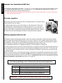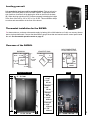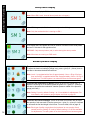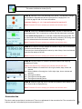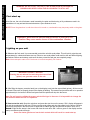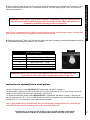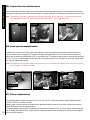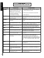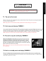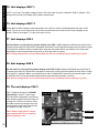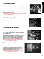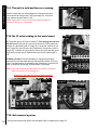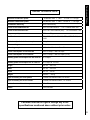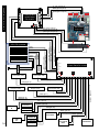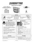
1
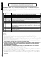
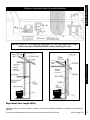
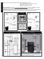
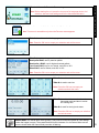
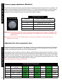
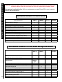
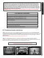
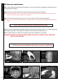
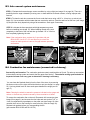
RAFAEL 55
inc.
Paromax
Efficency
94.5%
EPA
Certified
Version:
Important:
Press the left
upper corner of the
screen to increase
luminosity when the
screen is black.
AMERICA
(touch screen)
Important:
Close hopper lid
or main door.
60 seconds
delay before
unit will stop.
Report No.
120-S-01B-2
Approbation: ASTM E1509-04,
ULC S627-00,
ULC/ORD C1482-M1990
IMPORTANT : Read the manual before using the Rafael
USER MANUAL & MAINTENANCE
WARNING:
PROFESSIONAL INSTALLATION
IS HIGHLY RECOMMENDED
IMPORTANT INFORMATION:
Model:
Serial Number:
Improper installation, adjustment, alteration, or maintenance can cause injury, property damage, Purchase date:
or loss of life. For assistance or additional
Purchased from:
information, consult an authorized dealer.
Manufactured by Paromax
Blainville Qc
Canada J7C 5E2
Please note your serial number when
calling for technical support (see page 4)
Ver. RA-En-A 12.09A September 2012
Please note the battery comes shipped inside the hopper. Important: remove the battery before start-up.
Congratulations!
MESSAGE TO NEW OWNER
Thank You ! We Appreciate Your Business
The quality of execution of each of our stoves will provide you peaceful years of comfort.
Three steps to follow for the safest and most efficient performance of the unit.
1- Install it properly 2- Operate it correctly 3- Maintain it regularly
PAROMAX : The Passion of Renewable Energy
The RAFAEL is certified to burn: Premium And Low Grade (high ash) Wood Pellets, Corn Kernels And Wheat Grains.
WARNING: Use Fuel Listed Only. That carbon monoxide can result from using fuels
that are not recommended by Paromax.
Safety Advisory:
-A fire may result if your appliance is not properly installed. For your safety, follow the installation instructions.
-Contact local officials about restrictions and installation inspection requirements in your area.
-Local regulations and requirements can supersede those specified in this manual if more stringent.
The authority having jurisdiction (such as municipal building department, fire
department, fire prevention bureau, etc.) should be consulted before installation to determine the need to obtain a permit.
The installation of this unit must be in accordance with these instructions. Read them
carefully before installation. Keep this manual handy for future reference.
Package contents
Quantity
2
1
1
1
1
1
1
1
1
1
Description
User manual and Installation
AC Power Inlet cord
Plastic Cup
Black alligator clip for battery
Red alligator clip for battery
Fuse 500MA
7 amp battery back up
Poker tool
Ash pan
WARNING: Please read this entire manual before installation and
use of this multi-fuel burning room
heater. Failure to follow these instructions could result in property
damage, bodily injury or even death.
-Certification label ...................................................................... page 4
-Safety instructions .................................................................... page 5
-Installation
-Unit location ............................................................................. page 6
-Chimney types ......................................................................... page 6 & 7
-Mobile home installation .......................................................... page 7
-High elevation .......................................................................... page 7
-Negative pressure in the house ............................................... page 7
-Outside inlet Installation.............................................................page 8
-Pressure regulator ................................................................... page 8
-Battery supplied with unit ......................................................... page 8
-Level your unit ......................................................................... page 9
-Thermostat installation ............................................................ page 9
-Clearance and dimensions diagram ........................................ page 9
-Clearance table ........................................................................ page 10 & 11
Table contents
-Package contents of the RAFAEL............................................. page 2
-Chimneys schema .................................................................. page 11 & 12
-Control panel functions ............................................................ page 13 to 15
-Procedures steps for start up
-First start up ............................................................................. page 16
-To turn on your unit .................................................................. page 16 & 17
-Instructions for burning wood pellets........................................ page 17
-Instructions for burning corn or wheat...................................... page 18
-First use of the RAFAEL with corn or wheat ............................ page 18
-Preparing the unit for corn or wheat......................................... page 18
-Clinker prevention .................................................................... page 18
-Controlling the fuel bed (embers) level .................................... page 19
-How to measure the fuel bed height ........................................ page 19
-Pressure gauge setting ............................................................ page 20
-Fuel consumption correction .................................................... page 20
-Programming fuel consumption ............................................... page 21
-Thermostat mode ..................................................................... page 21
-Mixing mode ............................................................................. page 21
-Unit component’s maintenance program ..............................
.
page 22
-Maintenance guide .................................................................. page 23 to 27
-Error codes .............................................................................. page 28
-Troubleshooting ........................................................................ page 29 to 32
-Technical data ...........................................................................page 33
-Electrical diagram .................................................................... page 34
-Replacements parts ................................................................. page 35
-Warranty ................................................................................... page 36
3
PY
The security label is located on the back panel of the unit.
CO
Serial number of the unit
4
Certification label
01- DO NOT BURN GARBAGE OR FLAMMABLE FLUIDS SUCH AS GASOLINE, NAPHTHA OR ENGINE OIL AND DO NOT USE CHEMICALS OR FLUIDS TO START THE FIRE
02- Do not store any combustibles near to the unit in operation. Minimum clearance from the unit and to store combustibles are 4 feet or 1.21 meter. Store the combustible in a dry place
03- Do not use gasoline, gasoline-type lantern fuel, kerosene, charcoal lighter fluid, or similar liquids to start or freshen up a fire in this unit. Keep all such liquids well away from the unit while it is in use.
04- Do not operate the unit if the burn pot overfill with fuel. Turn off the stove and refer to the maintenance instruction.
Safety instructions
SAFETY PRECAUTIONS
05- Do not strike or slam shut the glass door, it may damage or crack the glass.
06- Do not use a substitute materials or components. Always replace by a Paromax part.
07- Do not operate the unit without burn pot ” tube” and the top ring or in invert position (upside down).
08- Do not burn treated material. Other materials such as wood preservatives, metal foils, coal, plastic, garbage, sulphur, or oil may damage the catalyst.
09- Do not add combustible to the burn pot by hand when the unit is in operation.
10- Do not lay the ash pan on combustible floors when the ashes are hot.
11- It is very important to ensure that the unit is installed in a safe manner. Be aware of fire prevention rules and laws in your area. All applicable National and Local codes must be met and complied with. Notify your insurance company of this unit.
Do not use makeshift methods or compromise in the installation.
12- We recommend a dealer authorized by Paromax to install your unit. If the unit is installed by an unauthorized installer, Paromax will not be held responsible for any malfunction related to the chimney including a poor performance of the unit.
13- The electrical connection required with the unit consists of AC power inlet cord to plug into a standard wall outlet (120 volts AC) with ground connection.
14- It is strongly recommended to install a smoke detector and an ABC type fire extinguisher near the unit. Using a power surge protector bar helps protect the electrical components of the unit and is highly recommended.
15- Your unit requires periodic maintenance and cleaning. Failure to maintain your stove may lead to a poor performance, smoke spillage in your home or even a more dangerous situation.
16- To start your unit, always use a specified and approved fire starter gel (gel approved for multi-fuel stove). Never use a flammable liquid like gasoline, barbecue fire starter or alcohol. Failure to comply with this may create a hazardous
situation and will void all warranties.
17- Never attempt to re-light your unit until the unit has fully cooled down. Never start your unit with a gel fire starter when the burner is still hot, it could cause severe burns. Wait until the unit and the burner are completely cold before you turn it back on.
18- Manual feeding (primer) should only be used to initiate fuel supply to the burner when the hopper is empty. Do not use the manual feed procedure to start your unit, it will cause smoke inside the combustion chamber.
19- Ensure that the ash pan door is securely closed at all times. Air pressure could ignite the fuel accumulated in the burn-pot creating an overdraft condition in the combustion chamber altering the performance of the burn-pot.
20- The fuel supply will not operate if the main door or the hopper door are not closed.
21- The unit must be cold before any attempt to clean the main glasses. Do not use detergent containing abrasives to clean the windows or any other parts of the stove. Use only recommended products found at your local hearth shop for this type of cleaning.
22- Ashes must be disposed in a metal container with a tight lid and placed on a non-combustible surface well away from the house. Wear gloves when handling or emptying the ashes as it can still be very hot.
23- Never use a vacuum cleaner to remove ashes from the stove or the burner or the ash pan, unless the stove is cold for several hours.
24- Do not store or install the battery inside the unit. Risk explosion in case of heat.
5
Installation
Unit location
For optimum benefit with your appliance, speak to an authorized Paromax Dealer concerning the unit location.
The location for your appliance can be a factor in how it will perform. Choose an interior location where the pellet
vent will not be affected by any external interference, ex; trees, bushes, walls or fencing (refer to “Vent Termination
Requirements” section at page 10). Install the unit according to recommendations made on “clearances” section at
page 10 or according to the safety label fixed on the unit.
Always use a pellet vent double wall type PL with a inside diameter of 3” / 7.6 cm or 4” / 10.2 cm maximum. You
can pass the pellet vent system thru the wall behind the unit. Paromax recomand to use rigid pellet vent pipe up
thru the existing chimney.
Ensure that all clearances to combustibles are met as per the safety label and the diagrams on “Clearances” section at page 9.
This appliance may need outside air if there is a negative pressure within the room. Make sure the outside air supply for the unit does not come from a garage, an attic or any restricted non-ventilated space.
The floor mat under the stove must be of non-combustible material, i.e. cement, ceramics, etc... and must extend
6” or 15.2 cm for the sides and front. Refer to the diagrams on “Clearances” section at page 9.
Requirement: Avoid any PL pellet vent quick connection (twist lock) in the attic or roof space, closet or similar concealed space, floor or ceiling. Do not use different brand or models of vent pipe on the same vent pipe installation.
WARNING: DO NOT INSTALL A FLUE DAMPER IN THE EXHAUST VENTING SYSTEM
OF THIS UNIT. DO NOT CONNECT THIS UNIT TO A CHIMNEY FLUE SERVICING ANOTHER APPLIANCE. DO NOT CONNECT TO ANY DISTRIBUTION DUCT OR SYSTEM.
Pellet vent size (PL)
IMPORTANT: Always use a double wall 3” / 7.6 cm or 4” / 10.2 cm PL type pellet vent approved for venting wood
pellets fuel or agriculture fuel. A tight seal (silicone or aluminum tape) is recommended on each section of the
pellet vent to prevent smoke leakage and odors. The pipe connecting to the unit and the outer wall joints located
between the pipes also need to be sealed with high temperature silicone or aluminum tape. The maximum pellet
vent height is 35 feet or 10.6 meter. Use a wall thimble for flammable wall or collar for cement wall. Seal the exterior pellet vent with silicone to create a vapor barrier.
It is not recommended to seal the inner walls joints already containing a pre-installed silicone or rubber
sealant by the manufacturer of the pellet vent. Do not use a perforated outer wall pellet vent flue channeling fresh air to the burner.
WARNING: DO NOT INSTALL IN SLEEPING ROOM
CAUTION: THE STRUCTURAL INTEGRITY OF THE MANUFACTURED
HOME FLOOR, WALL AND CEILING/ROOF MUST BE MAINTAINED
6
Since this is a multi-fuel unit, it is recommended to choose an approved venting system. If you choose wood pellets, a double wall 3” or 7.6 cm stainless steel pipes are recommended. For agriculture fuel, it is recommended to
use double wall PL type 3” or 7.6 cm stainless with higher quality durability. Refer to the vent pipe manufacturer for
more details.
Installation
Chimney types (continued)
Do not use a non-approved pipe for your vent system. i.e., Dryer vent, “B” vent for gas vent, PVC/plastic pipe or
single wall chimney system.
Please note that the length of a horizontal venting system shall not exceed 24” or 61 cm.
Always vent to the outside atmosphere and never into enclosed spaces, i.e. garage, car port etc. Venting systems
can generate heat and smoke.
WARNING: HOT UNIT WHILE IN OPERATION.
KEEP CHILDREN, CLOTHING AND FURNITURE AWAY.
ANY CONTACT MAY CAUSE SKIN BURNS
Mobile home installation
Use PL type chimney for immediate evacuation outside the mobile home. Refer to the chimney diagram for proper
exhaust installation. The space heater is to be connected to a factory-built chimney conforming to CAN/ULC-S629,
standard for 650 degrees F or 343 degrees C. For proper clearances, remove outside sections of the chimney
when displacing the mobile home. Outside air inlet must be provided for combustion and be unrestricted while unit
is in use. Refer to outside inlet installation on page 8. The unit must be securely fastened to the floor by using one
bolt in the front and two bolts in the back of the unit.
Recommendation: Chimney installation in a windy area must rise above the roof. It may be normal for ice build-up around the cap during cold or windy days.
High elevation
High altitude reduces air capacity to the burner. To help increase the air speed, a vertical chimney above the roof is
recommended to create a natural air flow. Refer to the chimneys diagrams on page 11 and 12.
Negative pressure in the house or starvation air
The use of a bathroom fan, dryer, kitchen hood fan, etc, can create negative pressure, especially in new air tight
homes. Combined, these fans consume three times more air than the combustion fan on the unit, and may create
a significant drop of pressure therefore a lack of air to the burner that may cause a fire extinguishing. Paromax
suggest you take a gauge reading before, during and after the use of your appliances and/or fans to check the
pressure variations. If the pressure changes, Paromax recommends installing an outside air intake. Refer to fresh
air installation for more information on page 8.
7
Installation
Outside inlet Installation (FA01 kit)
Use a coupling (pipe thread) to increase 1” - 2.5 cm to 2” - 5 cm, install a one way valve, maximum length is 5 feet
or 1.5 meter. For more than 5 feet or 1.5 m, increase to 2.5” - 6.3 cm diameter for a maximum of 10 feet or 3 m
total. Install cap with a grill to prevent rodent’s intrusion.
Note: Seal outside pipe joints and wall outlet with silicone to prevent water from entering. To view air inlet location, refer to page 9 (width picture).
Pressure regulator
Image 1
Natural draft may create a malfunction due to increased pressure. If necessary, obtain
a plate restrictor from your dealer.
To install the plate restrictor, refer to the image 1 to view the air outlet. There are 4
nuts and bolts to be removed from the air outlet by using a 7/16 or 11 mm wrench
socket. Install the pressure regulator on the combustion fan air outlet; take care to replace the white seals on each side of the pressure plate. Replace the bolts, washers
and nuts on the air outlet and tighten the bolts for a hermetic pressure regulator.
Battery supplied with the unit
This battery will allow uninterrupted operation of your unit in case of power failure. Please note that this system
does not replace the standard electrical power of 120 volt AC of the unit. This is a battery backup feature. When
fully charged, it can last 4 hours or less depending on heat level setting (1-5) used. It is recommended to always
leave the battery connected. The battery will be recharged when the power comes back.
For an extended performance, we suggest purchasing a 12 volt car battery for a longer use.
If a power outage occurs for more than 3 seconds and there is no battery connected, the fans will stop and there is
a risk of smoke. When electricity is restored, the control panel will display the error code VOLT 1. If the unit is still
hot, the fans will start to cool down the unit. In case of interruption of less than 3 seconds, the unit could continue
to operate normally.
Option: To use the unit on 12 volt continuously as your main power, we recommend to by-pass the power inverter.
Disconnect inverter the black wire identified on COM and the red wire identified on V1 on the power inverter and
then connect these wires directly to the 12 volt DC source. The Warranty does not cover any polarity inversion
that may damage the control panel (see picture 36 on page 32).
Notice: Your battery is provided with an insulation to prevent ground contact.
To avoid any discharge, never sit the battery directly on the ciment floor.
Step
1
2
3
4
8
Battery connection order to follow
Connect the red clip to the positive battery terminal +
Connect the black clip to the negative battery terminal Connect the battery red wire to the unit red wire.
Connect the battery black wire to the unit black wire.
WARNING: Children should be kept away from the hot unit. Installation
Leveling your unit
It is essential to level your unit for a stable fuel bed. First put a level on
the side of the base (letter A) and use metal “spacer” to adjust the lowest
side. And then, level the front by placing the level on the front of the base
(B). When burning agriculture fuel, Paromax suggests increasing the height
of the front of the unit by 1/4” to 3/8” or 6 to 10 mm. This modification helps
to reduce ash accumulation in the front of the burner.
B
A
Thermostat installation for the RAFAEL
For thermostat use, purchase a thermostat supply by battery (AA or AAA batteries or 9 volt) or a mercury thermostat or wireless thermostat. Connect the thermostat to purple wires that are located near the control panel inside
the unit. See thermostat operation mode on page 21
Clearance of the RAFAEL
BACKWALL
6”15
CM
3”7.6 CM
SEE
NOTE
IT
38”96.5 CM
MAX
6”- 15 CM
3”7.6 CM
N
UNIT
4”10 CM
U
8”20 CM
NON-COMBUSTIBLE
FLOOR PROTECTOR
ADJACENT WALL
*6”15.2
CM
SEE
NOTE
3”7.6 CM
Height and Depth
*6”15.2
CM
*6”- 15.2 CM
FRONT
UNIT
Width
4” - 10.1 cm
Safety
cover
A = 2 1/2”
6.3 cm
34 3/4” - 88.2 cm
Handles
B = 3/4”
1.9 cm
Exhaust
C = 3 1/2”
8.9 cm
D = 14 1/2”
36.8 cm
Fresh air
E = 6 1/4”
15.8 cm
F = 5 7/8”
14.9 cm
A
23 1/4 - 59 cm
B
C
D
E
F
22 3/8 - 56.8 cm
9
Installation
IT IS RECOMMENDED THAT YOUR PELLET STOVE BE INSTALLED BY A PAROMAX AUTHORIZED DEALER/INSTALLER.
CLEARANCE TABLE: Use in conjunction with diagram on page 11 for allowable exterior vent
locations for both horizontal and vertical terminations. Clearances may only be reduced by means
approved by a regulatory authority.
A
Minimum
24” / 61 cm
A
12” / 30.5 cm
B
48” / 122 cm
C
12” / 30.5 cm
D
24” / 61 cm
E
24” / 61 cm
F
12” / 30.5 cm
G
12” / 30.5 cm
H
36” / 91.5 cm
I
36” / 91.5 cm
J
12” / 30.5 cm
K
24” / 61cm
Description
Above lawns, top of plants, wood or any other combustible materials.
Above non-combustible surface such as cement and gravel.
From beside/below any door or window that may be opened.
From above any door or window that may be opened.
To any adjacent building, fences and protruding parts of the structure.
Below any eaves or roof overhang.
To outside corner.
To inside corner, combustible wall (vertical & horizontal terminations).
To each side of center line extended above natural gas or propane meter/regulator assembly or mechanical vent within a height of 4.5 m above the meter/
regulator assembly.
From any forced air intake of other appliance.
Clearance to non-mechanical air supply inlet to building or combustion air
inlet to any appliance.
Clearance above roof line for vertical terminations.
NOTES :
1. Do not terminate the vent in any enclosed or semi-enclosed areas that can build up a concentration of smoke.
2. Vent surfaces can become extremely hot. Keep children away from such areas. Non-combustible shielding or guards may be required.
3. Termination must exhaust above sea level and the inlet elevation. It is recommended to have a short vertical run which will help in the event of total power failure.
4. If the unit is incorrectly vented or the air to fuel mixture is out of balance, a slight discoloration of the exterior of the house might occur. Since these factors are beyond our control we offer no guarantee against such incidents.
5. When installing into an existing masonry chimney, you will probably need a short horizontal section to clear the lintel and allow the hopper lid to open.
6. Vent terminations shall not be recessed into walls or siding.
7. A vent shall not terminate directly above a sidewalk or paved driveway which is located between two single family dwellings and serves both dwellings.
8. If the vent termination is children accessible, a certified guard shall be installed as specified in CGA B149 installation Code in Canada. Note: Local codes or regulations may require different clearances.
10
Clearances table
Minimum clearances table for a wall installation
INSTALL VENT AT CLEARANCES SPECIFIED BY THE VENT MANUFACTURER
Refer to the norm CAN/CSA-B365-01 before installing the vent.
12” or
30.5 cm
MIN.
12” or
30.5 cm
MIN.
Stove
Chimney types
Minimum
distance
3” or 7.6 cm
Minimum
distance
3” or 7.6 cm
Stove
Equivalent Vent length (EVL)
Venting your unit is crucial for optimum operation. There are five different installation examples recommended by Paromax.
The unit uses the combustion fan to move air from the exhaust to the chimney.
(Next on page 12)
11
Chimney types
Restriction may come from several different items.
Each 45 degree elbow = 3 EVL
Each 90 degree elbow and tee clean out = 5 EVL Each foot of horizontal run = 1 EVL Each foot of vertical run = 0.5 EVL
Higher Altitude 3000 ft or 914 m: The vent pipe must be above the roof. If the EVL are Inferior to 15, install a
vent pipe of 3” or 7,6 cm. If the EVL are superior to 15, install a vent pipe of 4” or 10,2 cm.
Lower Altitude 2999 ft or 913 m: For the other installation with a vent pipe of 3” or 7,6 cm, the installation rule is
the sum of 15 EVL or less. For a superior sum of 15 EVL and up, install a vent pipe of 4” or 10,2 cm.
Vertical cap
recommended
Total of
14.5 EVL
vertical
cap
vertical
cap
5 feets or 1.5
meter minimum
on vertical vent
6” or
15.2 cm
1” or
2.5 cm
5 feets or 1.5
meter minimum
on vertical vent
Stove
Sealing off the
top and bottom
of existing
chimney with
the new pipe is
recommended
3” or 7.6 cm pipe in an existing chimney
3” or 7.6 cm clearance to the chimney.
Type A chimney
Type A chimney clearances specified in chimneys
instructions
ceiling support
3” or 7.6 cm
clearance
L Vent to class A
chimney adaptor
Maximum
alcove
depth
38” or
96.5cm
Minimum
alcove
side
12” or
30.5cm
Support
bracket
Minimum alcove
height
60” or 153cm
Minimum
alcove
side
12” or
30.5cm
6” or
15.2
cm
Outside
air
12
Stove
Alcove installation
Storm collar
Flashing
Total of
14.5 EVL
Hearth pad
The flooring under the unit for alcove must be a non-combustible
material, i.e. cement, ceramics, etc, and must extend of at least 6”
or 15.2 cm for the sides and 12” or 30.5 cm for the front. Refer to the
diagrams on “Clearances” section at page 9.
Menu icon: this menu is divided into 6 tabs identified as 1 to 6.
Note: This menu is accessible only when the Paromax name appears.
Control panel functions
To start the unit: Press the Paromax logo.
Note: Before starting the unit, press the icon menu for language choice, fuel selection, date and time settings and for the thermostat activation.
Tabs 1: Is used to select the language.
Note: Press the OK icon to accept your selection and exit the menu.
Tabs 2: Is used to change or choose a fuel in the list.
Wood pellet RA05, use for premium pellets
Wood pellet + RA05, use for high ash content pellets
Corn kernel RA05, use for corn kernel, moist 9% to 18%
Wheat RA05, use for Wheat, moist 9% to 18%
Note: Press the OK icon to accept your selection and exit the menu.
Tabs 3: Is used to set date.
Tabs 4: Is used to set time.
Note: Press the OK icon to accept your selection and exit the menu.
Tabs 5: Is used to activate or deactivate the thermostat mode and also to review unit running time.
Tabs 6: Is used for the log book status.
Note: Press the OK icon to accept your selection
and exit the menu.
Manual feed: The manual feed mode (primer) is only used to fill the feed system at a first startup
or when the hopper is empty. The manual feed will function between 3 to 4 minutes. Make sure all
doors are closed when the manual feed procedure is flashing.
13
Control panel functions
Startup mode display
The first start up display is SM 1 mode.
Note: When SM1 is red, close all doors (main door or hopper).
When SM 1 is green, the first 4 minutes start-up mode will begin.
Note: Only the combustion fan is running on SM 1.
Then display SM 2 will appear and run for another 4 minutes for the wood pellets
fuel and 21 minutes for the agriculture fuel.
WARNING: Only the stop button (red) is active during the start up mode.
Note: All motors are running on SM2 mode.
Normal operation display
To access the heat level display, press on the flame icon (top left).
To adjust the heat level settings (orange icon), press + (plus) or - (minus) icons to increase or decrease the desired heat level.
Note: Level 1 is regulated with a flow of approximately 1 lbs or .45 kg of fuel per hour and level 5 is regulated with a flow of approximately 4 lbs or 1.81 kg of fuel per hour. The feed system is on when the flame icon becomes green.
To access the combustion air display: press on the fan icon (center left). To
adjust the incoming air to the burner, press the green icon + (plus) or - (minus) to
increase or decrease the combustion chamber pressure related to the pressure
gauge (mini-helic).
Note: Setting 5 is set by default. Setting 1 to 10 is available for adjustments. For more details, refer pressure gauge chapter and chart on page 20.
To access ash removal settings: Press on the trash icon (bottom left) to adjust
the quantity of ash removed: Press the green icon + (plus) or - (minus) to increase
or decrease the fuel bed height in the burner. For more detail, refer to page 19.
14
Note: Each type of pellet or agriculture fuel produces its own quantity of ash content per hour. Setting 15 is set by default; setting 11 to 20 are available for adjustments. The ash system is on when the trash icon becomes green.
Control panel functions
Menu 2 icon, is accessible only when the unit operates in normal mode. This mode is divided into 4 tabs (A to D).
Tabs A: Calibration of the fuel delivered to the burner. The calibration settings
can increase or decrease the amount of fuel per hour, ranging from -3 to +3. Refer to page 20 and 21 for more information.
Important: Setting +1, +2, +3 are not functional for heat level 5.
Note: Press the OK icon to accept your selection and exit the menu.
Tabs B: Press on the enable thermostat icon to activate or deactivate the
thermostat mode. The X in the top box confirms that the thermostat is activated.
Press enable mixing mode icon to activate or deactivate the mixing mode. The
X in the bottom box confirms that the mixing mode is activated. The mixing mode
can’t be selected when the thermostat is activated. See page 21.
Note: Press the OK icon to accept your selection and exit the menu.
Tabs C: The top time counter displays the number of days, hours, minutes and
seconds since last startup of the unit.
The lower time counter displays the number by order of days, hours and minutes
since the first startup of the unit.
Note: Press the OK icon to accept your selection and exit the menu.
Tabs D: Log book data is to review the operational status and analyzing possible error codes.
Note: Press the OK icon to accept your selection and exit the menu.
1A
4A
2A
5A
3A
1A = Meter indication of overall time. Left to right, months, days, hours and minutes.
2A = Meter indication of running time. Left to right, days, hours, minutes and seconds.
3A = The log book status.
4A = The log book recording date.
5A = The log book recording hours.
Tabs D: Press the Open log icon to view the list by dates of each startup of the
unit. Select a date to display the log.
Note: Press the OK icon to accept your selection and exit the menu.
Convection fan
This fan is used to propel hot air into the room. There is no adjustment for the convection fan. The convection fan
is factory set and is controlled by the heat level selected (1-5).
15
Procedures steps for startup
WARNING: DO NOT START THE UNIT IF THE GLASS DOOR IS CRACKED OR
BROKEN AND NEVER CLEAN THE GLASS WHEN IT IS STILL HOT.
First start up
At its first use, the unit will release a smell caused by the paint and the burning of oily substances used in its
manufacture. It may activate the smoke detectors. Open windows to vent.
NOTE: Since the glass door is cold when the unit is turned on, condensation may temporary settle on the glass.
WARNING: Never use the manual feed procedure to start your unit.
Caution: May cause smoke issues in the combustion chamber.
Lighting on your unit
1. Whatever the fuel used, it is recommended to start the unit with wood pellets. This will quickly raise the vent
temperatures for a better and faster start up. Failure to use wood pellets could result in slow and difficult lighting
procedures. Before each startup, make sure the burn pot and the ash pan are completely empty.
Note: Never attempt to start a fire if the burner is hot and completely full of ashes.
Image 2
WARNING FOR EMPTY HOPPER:
Starting the unit without first activating the manual feed
(primer) can generate smoke in the unit.
2. After filling the hopper, press the hand icon on the display to activate the manual feed (primer). All doors must
be closed. Doors are not properly closed if the display is flashing. The manual feed procedure will be in operation
approximately for 4 minutes to fill the feed system and few pellets will drop into the burner.
Note: Do not forget to validate the proper selected fuel type in the menu. It is impossible to change the fuel selection when the unit is in operation.
16
3. How to start the unit: Open the main door and press the start icon on the screen. SM 1 display will appear in
red and the combustion fan will start. Fill the cup with wood pellets and drop the pellets into the burner. Sprinkle
generously the pellets in the burner with an approved fire starter gel and mix well with the poker. Next, use a
match to light the fire starter in the burner and close the main door. SM 1 will turn green on the display and the
startup countdown mode will begin.
Some fire starter gels have a low alcohol content which will result in a weak start-up
WARNING: If the burner only produces smoke, immediately stop the startup procedure or normal mode by pressing the red icon on the screen. Wait until the unit is
completely cold before putting it back in operation.
Note: This is a mechanical device. Since it contains two fan motors and two auger motors, it is likely that
you will hear sounds from your appliance, these noises are normal.
Procedures steps for startup
4. SM 1 and SM 2 mode will scroll on the screen for a total of 8 minutes for wood pellets and 25 minutes for corn
or wheat. Note that the shutdown icon is accessible at all time. Once the startup period is over, the screen will
indicate the heat level 3.
5. Selecting heat levels; There is a 5 minutes time delay cycle when increasing or decreasing between each level
for wood pellet and twenty 20 minutes for corn or wheat.
Fuel chart information
Heat level
1
2
3
4
5
Image 3
Fuel per hour
Approximate 1 lb
- .45kg
Approximate 1.5 lbs - .68kg
Approximate 2 lbs - .91kg
Approximate 3 lbs - 1.36kg
Approximate 4 lbs - 1.81kg
WARNING: Never open the main door and the ash door at the same time, this could cause a fire extinction and generate smoke in the unit.
Instruction to optimally burn wood pellets
Use the 16 holes burner. Select WOOD PELLET combustible; see tabs 2 on page 13.
Recommendation: Open the air valve (only when unit is cold) to a minimum of 1/8” or 3 mm. The air valve is located near the fresh air inlet in the ash compartment, see picture 3.
For high ash wood pellet content, select WOOD PELLET + combustible, see tabs 2 on page 13. Open the air
valve to a minimum of 1/8” or 3 mm. In case of ash fusion (clinker), increase the ash evacuation and maintain the
fuel bed to 2” or 5 cm. Close the air valve if the ash fusion persists.
Note: Lightly tighten the top threaded disc with your hands when changing the burner. Install the ash box below the burner before installing the burner’s bottom threaded disc.
Paromax has no control over the quality or types of fuels available on the market
and will assume no liability for any malfunction related to the type of fuel used.
17
Procedures steps for startup
Instructions for burning high ash fuel
IMPORTANT: Wood pellet with high ash content (WOOD PELLET+) or agricultural products such as corn or wheat
requires more attention than for wood pellets. Please follow this instruction or you may risk a failure from the ash
removal system causing an accumulation or overflow in the burner and around the burner. These types of problems are your responsibility and are not considered as a malfunction but a non appropriate adjustment on the
control board. Wood pellets, corn and wheat fuel have different physical characteristics such as; moisture, grain
size and high ash content, therefore these guidelines and instructions will help you get a better performance and
understanding of your unit when using different fuel.
First time burning with corn or wheat
To familiarize you with corn or wheat, we recommend using wood pellets during the first days. When you are familiar with the functioning of the unit, you can switch to corn or wheat. Corn or wheat may leave a permanent white
deposit on the glass.
Note: Paromax recommends purchasing a second ash pan when the unit is set to heat level 4 or 5 for more than
24 hours. When the ash pan is full, there is possibility of creating a clinker or a fuel overflow outside the burner. It
is recommended emptying the ash pan everyday when burning agricultural combustibles.
Preparing the unit for corn or wheat
Image 3A
Install the 24 holes burner and close the air inlet (image 3A).
Note: Refer to the fuel bed level on page 19.
Note: Lightly tighten the upper disc with hands when changing the burner.
Install the ash box below the burner before installing the burner’s bottom
threaded disc.
Clinker prevention
In many cases, the use of certain recommended fire starter gels or materials can cause the beginning of a clinker
formation. In the event of a clinker formation during the first 90 minutes, you can use a “poker” to gently disturb the
fuel bed (embers) to continue its operation as before.
Note: If you must open the main door while the unit is running, always wear gloves and open the main door slowly
and for a very brief moment to prevent the extinction of fire.
WARNING : Never open the main door (glass) and the ash door at the same time,
this could generate smoke. Please inspect the door gaskets periodically.
18
Paromax has no control over the quality or types of fuels available on the market
and will assume no liability for any malfunction related to the type of fuel used.
If the fuel bed (embers) is too high or too low in the burner, follow the following guidelines to help you control and
stabilize the fuel bed.
How to measure the fuel bed height
Measured space between the burner top to the fuel bed should be 5” or 12.7 cm.
Note: A line is engraved inside the burner and serves as a reference.
Fuel bed (embers) height
Refer to steps A, B, C when the fuel bed remains at the burner
top with settings for the combustion fan at 5 and the ash removal
system at 15.
A-Gradually increase the combustion fan of 1 level
until the display shows number 6.
Controlling the fuel bed (embers)
Controlling the fuel bed level (embers)
B- Gradually increase the ash removal of 1 level
until the display shows number 16.
5” or
12.7cm
Fuel bed
2” or 5 cm
C- Check after one hour if the fuel bed has decreased. If not, repeat steps A and B by 1 level. If necessary, you may repeat these
procedures a few times. Refer to chapter Fuel consumption on page 20 and 21 if maximum settings are on the combustion fan
and the ash removal.
Note: Memorize new parameters for the combustion fan and the ash removal system in order to apply them at the next start-up.
Refer to steps A, B, C when the fuel bed remains in the burner’s bottom with settings for the combustion
fan at 5 and the ash removal system at 15.
A- Gradually decrease the combustion fan of 1 level until the display shows number 4.
B- Gradually decrease the ash removal of 1 level until the display shows number 14.
C- Check after one hour if the fuel bed has increased. If not, repeat steps A and B by 1 level. If necessary, you may repeat these procedures a few times. Refer to chapter Fuel consumption on page 20 and 21 if minimum settings are on the combustion fan and the ash removal.
D- For the loss of the fuel bed (embers) while burning wood pellets when the combustion fan and the ash removal system are at the minimum settings (1 and 11): Reduce the opening of the air inlet, this will help increase the fuel bed on a long-term (4 hours) period (see Image 3 on page 17). According to the pellets used, it is possible that the air inlet shall be closed for better control of the fuel bed.
Note: Memorize new parameters for the combustion fan and the ash removal system in order to apply them at the next start-up.
Paromax has no control over the quality or types of fuels available on the market
and will assume no liability for any malfunction related to the type of fuel used.
19
Pressure gauge setting
Pressure gauge adjustment (Minihelic)
The mini-helic indicates the pressure generated inside the combustion chamber while the unit is in operation. The
pressure varies accordingly to the selected heat levels (1 to 5). To follow the suggested chart, press the combustion fan icon (green) indicating a plus or minus to increase or decrease pressure. 10 settings are available to
calibrate the unit accordingly to the chart. The setting 5 will appear by default.
Pressure gauge chart
Pressure gauge
Heat level
Pressure indicated on the gauge
1
Ranges from .08 to .12 W.C
2
Ranges from .13 à .17 W.C
3
Ranges from .17 à .23 W.C
4
Ranges from .30 à .35 W.C
5
Ranges from .40 à .50 W.C
Important: The pressure indicated on the chart may vary accordingly to the fuel type. The height of the fuel bed dominates over the pressure chart. The moisture and / or size of the fuel may vary the pressure.
Note: Always refer to the fuel bed (embers) height in burner before decreasing or increase the pressure displayed on the gauge.
Consumption correction
Adjustment for fuel consumption /hour
20
Each heat level is factory programmed. The quantity of fuel per hour is displayed in the chart below. The length or
moisture can influence the flow per hour. Wood pellets vary in length from one manufacturer to another and the
moisture content and grain size also vary and can influence the flow.
Use the heat level 3 as a reference (see chart). Steps to follow: Empty the hopper and fill it with 40 lbs or 18.2kg
of fuel. Before startup, fill the measuring cup with wood pellets from another bag and start normally. Verify hopper
level after 16 hours of operation. To view how many hours, refer to page 15 tabs C for duration time. Then, check
every hour to see when the hopper is empty. A bag of 40 lbs or 18.2kg should last approximately 20 hours on heat
level 3, (40 lbs divided 2 lbs/h or 18.2kg divided .91kg = 20 hours)
Note: Refer to page 21 for adjusting the fuel flow.
Fuel chart and timing rate
Heat level
Flow per hour
(average)
Pellet ON
Pellet Off
Corn On
Corn Off
Wheat On
Wheat Off
1
1 lb
-
0.45kg
2 sec
16 sec
1 sec
15 sec
1 sec
12 sec
2
1.5 lb -
0.68kg
4 sec
19 sec
1 sec
11 sec
2 sec
13 sec
3
2 lbs -
0.91kg
5 sec
17 sec
2 sec
14 sec
3 sec
15 sec
4
3 lbs - 1.36kg
5 sec
11 sec
3 sec
15 sec
5 sec
14 sec
5
4 lbs - 1.81kg
7 sec
10 sec
3 sec
10 sec
6 sec
11 sec
Programming fuel consumption
How to program the fuel consumption on the control panel
To adjust the fuel consumption per hour, start the unit and wait for the display to show heat level 3. Go to menu
and the combustion calibration will appear. The factory setting default should be zero.
Reference table for heat level 3
If the results of the flowed time
(empty hopper 40 lbs -18.2kg) is
17 hours
Ajust the combustible calibration to
the numbers suggested below
18 hours
-2
19 hours
-1
20 hours
21 hours
0
+1
22 hours
+2
23 hours
+3
-3
Thermostat mode
The thermostat mode is very simple and regulates automatically the room temperature. For pellets, the heat level
1 is the minimum and the heat level 3 or 4 are used for the maximum power. For corn or wheat, the heat level 2 is
used for minimum power and the heat level 3 or 4 is used for maximum power. When the red heat level number 3
or 4 appears, the thermostat is on full power.
Note: Refer to the page 15 on tabs B to activate a thermostat when the unit is functioning.
Refer to page 13 on table 5 when unit is in standby mode.
Mixing mode
Paromax created the mixing mode on normal operation to disturb the fuel on heat level 1, 2 and 3.
Every 12 hours on the same heat level setting, the mixing mode well increase by 1 heat level for 5 minutes to
regenerate the fuel bed. After 5 minutes, the heat level returns to your selected level.
Thermostat functions
Caution: When the thermostat mode is activated without a thermostat installed, the heat level 1 will appear after the startup.
Refer to page 15 on table B to activate the mixing mode when the unit is running and press Enable mixing mode.
An X will appear in the box.
Note: The mixing mode is deactivated when the thermostat mode is activated.
21
Stove’s components maintenance program
WARNING: Failure to clean frequently the unit may result in poor performance and hazardous situations. Never clean the unit when hot. Refer to combustible schedule below.
Burn-pot and combustion fan: Refer to maintenance on page 24 and 25 for soot, creosote
and any ash accumulation.
Maintenance Schedule For Wood Pellets
Unit components
Remove ashes in burn-pot
Check the ash removal system
Check battery contacts and performance
Vacuum out the combustion chamber (step 1)
Empty ash pan
Clean the burn-pot jets
Clean the convection pipes system
Clean the the combustion fan (flywheel)
Clean the combustion chamber (step 1 and 2)
Clean the convection fan (flywheel)
Inspect chimney joint’s seals
Clean the chimney
Each
start up
X
X
X
Every 2
Weekly
Monthly
Every
2 months
X
X
X
X
X
X
X
X
Annual
Maintenance Schedule For Corn, Wheat and high ash content
Unit components
Remove ashes in burn-pot and clean the inner wall of
burn-pot (see burn-pot maintenance)
Check the ash removal system
Empty ash pan
22
Check battery contacts and performance
Vacuum out the combustion chamber (step 1)
Clean the burn-pot jets
Clean the convection pipes system
Clean the the combustion fan (flywheel)
Clean the combustion chamber (step 2)
Clean the convection fan (flywheel)
Inspect chimney joint’s seals
Clean the chimney
Each
start up
Every 2
Weekly
Monthly
Every
2 months
X
X
Every 2
days
X
X
X
X
X
X
X
X
Annual
Tools required for maintenance
Maintenance guide
IMPORTANT: Before each start up, it is recommended to empty the ashes and disposal of ashes
should be placed in a metal container with a tight fitting lid. The closed container of ashes should
be placed on a noncombustible floor or on the ground, well away from all combustible materials,
pending final disposal. If the ashes are disposed of by burial in soil or otherwise locally dispersed,
they should be retained in the closed container until all cinders have been thoroughly cooled. Other
waste shall not be placed in this container. Ash container needs to be moved outdoors, immediately. Keep the metal container far of the children.
WARNING: Embers can stay hot for a long time after the fire has been extinguished.
Ratchet and extension of 6’’ / 5 cm
Socket of 1/4” / 6 mm, 5/16” / 8 mm, 11/32” / 9 mm, 7/16” / 11 mm and 9/16” / 14 mm
Allen keys of 1/8” / 3 mm, 5/32” / 4 mm and 3/16” / 5 mm
Flathead screwdriver, Phillips head screwdriver # 2 (star)
Pliers for retaining ring
Hammer
Drill and a 3” / 7.6 cm round steel brush
Long bristle toothbrush or long bristle steel brush
Commercial vacuum cleaner with filter
High temperature lubricant anti-size copper base type
M1- Combustion chamber maintenance
STEP 1: Only when the unit is cold, we suggest using a filter vacuum cleaner to remove ashes (do not use a
household vacuum cleaner or central vacuum type) accumulated around and in the burner (see image 4). Use
a bristle brush to remove the ashes on the convection system pipes and two air inlets (see image 5). Clean the
inside of the door.
Note: Use a special bag or filter to eliminate any ashes leaks in the room.
Step 2: For a deep cleaning, after step 1, open the four clean-out doors located inside the combustion chamber (see image 6). It may be necessary to use a hammer to lift these doors upwards and tap gently on side
walls to remove the accumulated ashes that are not accessible with the vacuum.
Note: Before reinstalling the clean-out doors, see the section on the
combustion fan maintenance chapter M4 on page 25
Image 4
Image 5
View of the convection
tubes
Image 6
23
Maintanance guide
M2- Burn-pot maintenance
Step 1: Tap counter-clockwise with a flat screwdriver on one of the teeth of the threaded ring. Small strokes are recommended (see image 7).
Step 2: Unscrew counter-clockwise the cylinder with gloves for better grip (see image 8). Note: If the cylinder does not turn, loosen the two bolts supporting the ash box beneath the burner by using a 9/16” or 14 mm wrench (see image 13 on page 25).
Step 3: To clean the burn-pot holes, use a 1/8” or 3 mm rod from outside to inside (see image 9).
Note: Make sure you put the burner tube back in the right direction: the angled holes upward and straight holes down.
Note: Install the ash box before installing the burner tube
Step 4: Clean the threads before installing the burner (steel brush). See image 10 and 11. Lubricate threads with
high temperature grease. Screw lightly the cylinder and ring clockwise See image 8 and 12.
Note: To replace the burner: Always use original Paromax parts available from your dealer.
WARNING: PROTECT YOUR EYES WITH SAFETY GLASSES IF USING A DRILL EQUIPPED WITH A STEEL BRUSH.
Note: Tighten the threaded ring with only your hands when cleaning the burner during maintenance. Do not use any tools for tightening.
Image 7
Image 8
Image 9
Clean
the holes
with a
rod
Image 10
24
Threaded
bottom
Image 11
Image 12
STEP 1: Evaluate the three ash auger screws condition by using a light (see image 10 on page 24). There is a
possibility that the sugar released by burning corn or wheat adheres to the ash screws, causing improper ash
removal.
STEP 2: To clean the ash box: unscrew the 2 nuts under the burner using a 9/16” or 14 mm key or socket (see
image 13). Use a container with hot water that can receive the ash box. Soak the ash box for half hour (see image
14) and peel the sticky deposits by using a flat screwdriver. Soak again if necessary.
STEP 3: Lubricate the three sprockets with high temperature grease
before re-installing (see image 15). When installing the ash box, push
completely to the back of the unit and then go forward 1/8” or 3 mm before completely tightening the nuts.
Image 13
Nuts
Note: If the mechanism jams, replace the 3 sprockets with part #RA-10-655. Use a 1/8” or 3 mm Allen key to unlock the screws on each sprocket. Leave a slim gap between sprockets and bracket.
Image 14
Ash
screws
Image 15
Maintenance Guide
M3- Ash removal system maintenance
Image 16
Copper sleeve
Snap
ring
Sprockets
Shaft
Ash motor
Hex nuts
M4- Combustion fan maintenance (connected to chimney)
Soot and fly ash formation: The combustion products contain small particles of fly ash. Fly ash may accumulate
in the exhaust venting system and restrict the flue gases from flowing. . The exhaust venting system should be
inspected at least once every year to determine if cleaning is necessary.
You can clean the flywheel directly from the front of the stove, by accessing
the clean out door on the right side behind the burn-pot (see image 6 on page
23). Use long bristle brush to clean each space between the wings (see image 17).
Image 17
Note: Cleaning the wheel increases the pressure indicated on the gauge and
reduce or eliminate any vibration caused by the accumulation of ashes.
To remove the combustion fan on the unit: Disconnect all A connectors (see
image 32 on page 31) and unscrew the four bolts and nuts (socket 7/16” or
11mm) for separate the pipe adaptor on the pellet vent (see image 18). Now
unscrew the 4 nuts on the housing for remove the fan (refer the image 18).
Replace both gaskets before you re-assembling the fan.
(part number #RA-10-560 and RA-10-570).
Image 18
25
Maintenace Guide
M5- Convection fan maintenance
Remove the side panel (see image 19) to access the convection fan (see image 20). Use a bristle brush to clean
the spaces of each wing of the flywheel (see image 21), which will help to increase the air flow blown into the room
Note: The cleaning of the wheel increases the volume of hot air blown into the room. To remove the convection fan: unplug all B connectors and remove the two nuts 7/16” or 11 mm (see image 20).
Image 19
Image 21
Image 20
M6- Feed system maintenance
At least twice a year or more often, empty the hopper to clean fine particles accumulated at the bottom with a
vacuum cleaner (refer to image 22). To replace the feed motor (part #RA-10-470), remove the back panel and
unlock the set screw on the shaft with 5/32” or 4 mm Allen key. To replace the nylon sleeve: Unscrew the two bolts
(7/16” or 11 mm) on the feed plate holder and slide out the feed auger screw. Use pliers to take off the back retaining ring and replace the bushing.
Note: Reinstall the vacuum switch holder and the ground wire connected on the plate holder bolts: make sure the vacuum switch is installed vertically.
Image 22
Image 23
Image 24
Nuts
Feed system
ground wire
Feed motor
Nylon
bushing
Hex
nuts
M7- Glass replacement
It is recommended to replace the glass on your unit with a 3/16” or 5mm pyro-ceramic high temperature glass
(1600F or 870 C) if cracked or broken.
Use any type of gloves suitable to handle broken glass and carefully remove any pieces of glass from the door
frame. Dispose of all broken glass properly.
26
To replace glasses: Unscrew the 8 retaining nuts and remove brackets (11/32” or 9 mm socket). Replace the gasket if needed (Part #RA-10-750). Properly lay the new glass centered in the middle joints and do not over tighten
the nuts on the brackets.
For a better air tightness check gaskets of the main door and ash door
every two months and at the beginning of each season. How to verify:
Use a piece of paper (1” or 2.5 cm wide) between the door and the unit
(image 25). If there’s very little resistance when pulling the paper, pinch
the gasket with your fingers to regain roundness. Repeat it in different
locations around the doors. If you must replace your gaskets, use only a
dense gaskets with high temperature silicone (600F or 315C) available
from your dealer.
M9- Battery
Maintenance Guide
M8- Gaskets
Image 25
Strip of paper
Image 26
Check if the grips are well connected on the battery poles (red to red and
black to black). Check periodically if the unit will run off the battery. Start
the unit without a flame (cold) and disconnect the AC power from the
wall. Clean the battery’s connection if the unit stops during the test.
Note: Never place a battery directly on concrete as this can damage or discharge it.
M10- Burner
During maintenance, if the burner is difficult to screw, check the burner’s cylinder to identify damaged threads (see
image 9 on page 24). To repair threads: Use a hacksaw to correct threads deformation or any metal excess. Go to
chapter M2 at page 24 for dirty threads.
M11- Cleaning the Unit
When the unit is cold. To clean the glass and remove ash and fly ash, use a standard cleaning product. To remove creosote on glass, refer to your dealer for adequate products. Use a soft and non abrasive cleaner to clean
paint parts.
M12- Creosote formation and need for removal
It is imperative to do a complete cleaning of the chimney before the beginning of each season. Guidance on minimizing creosote formation and the need for periodic creosote removal. The chimney should be inspected periodically during the heating season to determinate if a creosote build-up has occurred. If a significant layer of creosote
has accumulated (1/8” / 3 mm and more) it should be removed to reduce the risk of a chimney fire. Open the T
clean out or unplug the unit on the chimney and use a light to inspect the creosote build-up inside the pellet vent.
To remove the creosote, use a 3” / 7.6 cm or 4” / 10.2 cm brush to clean the chimney. We suggest cleaning by a
professional.
Note: Refer to maintenance chapter M1 and M4 to remove any creosote accumulation.
WARNING: In case of creosote fire, immediately shut the unit off and call your local fire department.
27
Error Codes
28
ELECTRICAL
TROUBLESHOOTING CONTENT
Error code
THERMO 1
Possible cause
Possible Solution
1- Failed to start up properly. The
unit has not reached 130 F or 54 C
degrees and is in cooling mode.
1- Not enough fuel or gel in the burner. the alcool
content in the gel is no good.
2- The hopper is empty of fuel and
the unit is in cooling mode.
2- Fill the hopper and activate the manual feed.
3- If the Hopper is not empty.
3- Refer chapter T2.
THERMO 2
The unit is very hot and the fans run
at full speed. The high temperature
sensor is activated.
The convection fan may have stopped or the flywheel is dirty. The sensor 300F is defective. Refer to
chapter T3
THERMO 3
High temperature protection sensor
is defective.
Replace the high temperature sensor 300F. refer to
chapter
T4
VOLT 1
Input voltage less than 10.5 volts
DC.
Verified the output of the power supply or the battery
connections. Refer to chapter T5 and T15.
VOLT 2
No AC power and without the use of
the battery.
Hot unit will be in cool down mode automatically
when the AC power returns. Refer to chapter T5.
FUS 1
Feeding system fuse is burnt.
Feed system is jam, refer to chapter M6 and before
replacing the fuse see chapter T7.
FUS 2
Ash removal system fuse is burnt.
Ash system is jam, refer to chapter M3 and before
replacing the fuse see chapter T8.
FUS 3
Main fuse is burnt or bad connection
on the touch screen cable
Inrush current on main board. Replace the fuse see
chapter T9.
PRES 1
Low pressure (.08 w.c) or no pressure reading
Dirty combustion fan, refer to chapter M4.
Defective vacuum switch, refer to chapter T10.
The main door was open for more than 60 seconds.
or Increase fan settings to maintain higher pressure
over .1 W.C on the pressure gauge. Refer to page
20.
HOP 1
Hopper lid open.
Opened lid over 60 seconds or the switch is defective. Refer T11.
The unit is still running and cold
without an error code.
Replace sensor 130F protection, see chapter T2.
The unit is still running and cold
and the screen shows (cool down
mode).
Replace sensor 110F protection, see chapter T14.
The heat function mode is locked
on heat level 1, or 3, 4.
Thermostat mode is activated , refer to page 21 for
thermostat functions.
WARNING : Always unplug the AC source (wall outlet) of your unit before
performing any maintenance or repair.
Troubleshooting
ELECTRICAL
TROUBLESHOOTING GUIDE
T1- The unit will not start
Make sure the power cord is plugged into the unit and wall outlet. Check if the power converter green light is on. If not lit up, refer to Chapter T15.
Note: Unplug the AC current and let the battery operate the unit when testing your components.
T2- Unit stops and displays THERMO 1
How to verify if the sensor Thermo-Disk 130F is good when the hopper is not empty. Relight when the unit is cold
and wait 50 minutes to see if the same error code reappears. Replace the Thermo-disk (See image 33 on page
32) if the error code reappears. Refer to the feed system in chapter T7 if the error code does not appear.
Note: Unplug the AC current and let the battery operate the unit when testing your components.
T3- The unit is very hot and display THERMO 2
Thermo 2 is displayed on the screen: Open the left door and remove the
side panel (see image 20 on page 26) and verify that the 2 green wires are
connected to the protection (Thermo-disk) 300F (see image 27). Visually
inspect if the convection flywheel rotates (see picture 19 on page 26). If the
fan rotates, the flywheel needs to be cleaned (refer to section M5 on page 26).
Refer to section T9 if the fan is not running.
Note: Unplug the AC current an let the battery operate the unit when testing
your components.
Image 27
Thermo-disk 300F
T4- Unit is in standby mode and display THERMO 3
Thermo 3 is displayed when the high temperature protection is defective when the unit is in standby mode.
To replace the Thermo-Disk 300F: Remove left side panel of the control panel (see image 27 on page 29) and
remove the 2 screws (1/4” or 6mm).
29
Troubleshooting
T5- Unit displays VOLT 1
VOLT 1 error code: The battery voltage is below 10.5 volts or the converter is defective. Refer to Chapter T15 to
analyze the converter and Chapter M9 for battery maintenance.
T6- Unit displays VOLT 2
Power failure without a battery connected and the unit is still hot. Volts 2 will be displayed at the return of AC
power. The unit is in cool down mode. Verify if the convection fan turns while the error code is display on the
screen. Refer to the chapter T13 if the motor does not turn.
T7- Unit displays FUS 1
The feed motor is not functioning and the display show FUS 1 code: Replace the 500mA fuse (slow blow) in
F2 socket (see image 28). Remove the side panel to access the control panel and replace the fuse (refer to image
19 of page 26). Important: Refer to chapter M6 to clean the fuel system before you restart the unit. Note: After
maintenance, use the manual feed icon (primer) to test if the motor is running.
Note: Always unplug the AC source (wall outlet) and DC source (battery) before replacing any fuses.
T8- Unit displays FUS 2
The ash motor is not functioning and the display show FUS 2 code: Replace the 500mA fuse (slow blow) in
F3 socket (see image 28). Remove the side panel to access the control panel and replace the fuse (refer to image
19 of page 26). Important: Before you restart the unit, refer to Chapter M3 to clean the ash removal system. Note
to check the motor: Press the manual feed and check if the ash removal system is running.
Note: Always unplug the AC source (wall outlet) and DC source (battery) before replacing any fuses.
T9- The unit displays FUS 3
FUS 3: Replace the main fuse 500 MA
(fast acting) in socket F1 (see image
28). Remove the side panel to access the
main board to replace fuse (see image 19
on page 26). The fuse is not burnt: verify
the cable connections between the touch
screen and the main board. See the electric diagram on page 34 and 35.
Main board
Image 28
F3 socket
Note: Always unplug the AC source
(wall outlet) and DC source (battery)
before replacing a fuse.
30
F2 socket
F1 socket
PRES 1: The pressure switch no longer detects any pressure. The side
panel must be removed to access the vacuum switch (see image 29). Verify
the tubes connection between the Minihelic gauge and the vacuum switch
to the unit and see if the yellow wires are connected. After verifying, Press
the start mode without lighting the unit and check if the pressure indicates
on SM1 mode is over 0.3 W.C. Replace the pressure switch (see image 29)
if SM1 mode is displayed in red. Refer to Chapter T12 if the gauge does not
indicate pressure on SM1 mode.
Note: Unplug the AC current and let the battery operate the unit when
testing your components.
T11- Unit displays HOP 1
Troubleshooting
T10- Unit displays PRES 1
Image 29
Image 30
HOP 1: the hopper door has been open for more than 60 seconds when the
unit was in operation or failure or switch poor connection.
Hopper switch
T12- Combustion fan problems
No pressure could be related to a defective fan. Verify the
green wiring fan connection on controller A (see image 32). Do
a cold start and see if the flywheel is running by opening the
door on the right side (see image 31). Replace the combustion
fan if it does not rotate.
Image 31
Cooling flywheel
Low pressure could be related to a combustion fan’s flywheel
obstructed by ash (refer to chapter M4) or gaskets leakage
on both doors (refer to chapter M8). Refer to chapter M13 to
determine whether the chimney is not obstructed by ash.
Note: Unplug the AC current and let the battery operate the unit when testing your components.
T13- Convection fan problems
No room air could be related to a defective fan. Verify the
green wiring fan connection on controller B (see image 32).
Start the manuel feed and see if the flywheel is running by
opening the door on the left side (see image 21). Replace
the convection fan if the wheel does not rotate.
Note: Unplug the AC current and let the battery operate the unit when testing your components.
Image 32
A
B
31
Troubleshooting
T14- The unit is cold and fans are running
Image 33
Thermo-disk 130F
Open the right side door and unplug one of the two white wires
connected to the Thermo-disk 110F (see image 33). If the fans
stop, replace the disk Thermo-110F.
Note: Unplug the AC current and let the battery operate the unit when testing your components.
Thermo-disk 110F
T15- No 12 volts leading to the main board
Image 34
Pin
A- The green light is off (refer to image 37). First unplug the unit from
the AC source. Remove the cover on the converter, lift the plastic pin
using a very thin blade (refer to image 34). Loosen the case screw, (refer to image 35), then lift up the box. Replace the 5 amp fuse, (refer to
image 36). Connect the unit to the AC source and verify that the green
light and the screen are lit. Replace the converter if the green light is
off.
Image 35
B- Battery Trouble: Check if the battery is charged and properly
connected on red and black terminal clips supplied with the unit (12.8
volts). If no abnormality on the battery and connections: Check the DC
area 15 amp fuse (see image 36) and replace if necessary.
Note: Clean the connections of the battery for a better connectivity. (refer to the picture 26 to the page 27).
Phillips head screw
These fuses and labor are not covered by warranty.
Fuses from AC sector
Image 36
Image 37
Green light
Fuse from DC sector
T16- Ash removal system
32
A noisy ash removal may need to be lubricated. Refer to chapter M3 on page 25.
Minimum combustion power
8,500 Btu / hour = 1 lb/h - 2.5 KW / h = .45 kg/h
Maximum combustion power
34,000 Btu / hour = 4 lb/h - 10 KW / h = 1.81 kg/h
Combustion efficiency
86% net efficiency
Power of the combustion fan
25 to 45 cubic feet/min - .7 to 1.3 meter cube / min
Power of the convection fan
35 to 150 cubic feet/min (cfm) - 1 to 4.25 meter3 / min
Hopper capacity
55 lbs - 25 kg
Certification
EN 14785, UL, ULC-C1482, EPA, ASTM E1509, 84HUD
Emission of particles in the atmosphere
0.6 g/h
Power settings
5 levels
AC voltage required
120 volt to 240 volts / 50 or 60 hertz
Power consumption on 120 volts AC
Min .25 amps / Max .65 amps
Power consumption on 12 volts DC
Min 1.8 amps / Max 4.5 amps (13.8V)
Standby power consumption on 120 volts AC
0.10 amps
Standby power consumption on 12 volts DC
0.03 amps at 13.8 volt
Height
34 3/4” - 88.2 cm
Width
22 3/8” - 56.8 cm
Depth
23 1/4” - 59 cm
Weight
285 lbs - 129 kg
Type of chimney for wood pellets
Double wall stainless steel, PL version
Type of chimney for corn or wheat
Double wall stainless steel+, PL version
Inside diameter of the chimney
3” - 7.6 cm
Patent
US 6,336,449
Technical Data
RAFAEL TECHNICAL DATA
Paromax reserves the right to change any of the
specifications mentioned above without prior notice
33
Electrical diagram
1
red (pin 5 to pin 2)
black (pin 4 to pin 1)
white (pin 3 to pin 4)
green (pin 2 to pin 3)
J4
Communication
control board
PA-10-404
J5
1
1
1
J8
Mini2440v2
blue (pin 4 to pin 3)
orange (pin 3 to pin 9)
yellow (pin 2 to pin 10)
brown (pin 1 to pin 2)
(touch screen)
AC to DC converter
12 volts
battery
jonction
Control Panel PA-10-403
1
J1
Thermodisk 130F
Thermodisk 110F
Controller A
Motor output
0 to 10V input
12V input
Fan
A
Fan
B
34
Controller B
Motor output
0 to 10V input
12V input
J3
J2
Hopper switch
yellow (pin 9)
yellow (pin 10)
22
white (pin 1)
white (pin 2)
orange (pin 3)
orange (pin 4)
Pressure switch
10
Thermodisk 300F
yellow (pin 7)
yellow (pin 8)
red + (pin 11)
brown (pin 12)
black - (pin 13)
red + (pin 14)
blue (pin 15)
black - (pin 16)
green (pin 5)
green (pin 6)
black - (pin 17)
yellow + (pin 18)
Feed motor
Ash removal
motor
purple + (pin 21)
purple + (pin 22)
green
white
black
GROUND
AC NEUTRAL
AC LINE
(pin 1 to V1 output)
(pin 2 to COM output)
NEGATIVE BATTERY POSITIVE BATTERY +
(battery)
(battery)
COM NEGATIVE OUTPUT -
red + (pin 3 to pin 4)
black - (pin 4 to pin 3)
orange (pin 5 to pin 2)
white (pin 6 to pin 1)
1
red +
black black red +
V1 POSITIVE OUTPUT +
black - (pin 19)
grey + (pin 20)
Thermostat
Description
No. pièces
Touch screen kit
RA-10-400
Main control board kit
RA-10-401
Cable for touch screen
RA-10-411
Cable for main control board
RA-10-431
Fuse 500MA slow blow (sockets F2 , F3)
RA-10-405
Fuse 500MA fast blow (socket F1)
RA-10-410
Thermo-disc 110F (white wire)
RA-10-450
Thermo-disc 130F (orange wire)
RA-10-455
Thermo-disc 300F (green wire)
RA-10-460
Vacuum Switch (Gold magnetic)
RA-10-440
Auger feed or ash motors (Sgmada)
RA-10-470
Power supply (12 volts DC with charger)
RA-10-490
Combustion fan (Sn-Tech)
RA-10-510
Combustion steel flywheel
RA-10-540
Combustion fan gasket (white)
RA-10-560
Pipe adaptor gasket (white)
RA-10-570
Convection fan (SN-Tech)
RA-10-530
Convection plastic flywheel
RA-10-550
Speed control for combustion or convection fan
RA-10-520
Burner (threads) for Wood Pellet
RA-10-580
Burner (threads) for Corn and Wheat
RA-10-581
Top ring with threads
RA-10-590
Feed auger screw
RA-10-600
Nylon Bushing / feed system
RA-10-610
Trust washer
RA-10-615
Ash assembly kit
RA-10-640
Center ash screw
RA-10-645
Left or right ash screw
RA-10-650
Sproket
RA-10-655
Brass bushing (ash system)
RA-10-660
Ash shaft driver (motor to the ash box)
RA-10-665
Ash pan
RA-10-680
Main black door (Assembly parts not include)
RA-10-700
Ash black door (Assembly parts not include)
RA-10-705
Wood handle black
RA-10-710
Door handle black (metal)
RA-10-715
Door Latch
RA-10-720
Center glass Robax 5 mm
RA-10-725
Side glass Robax 5 mm
RA-10-730
Main door gasket (5/8” X 66” or 1.6 cm X 167 cm)
RA-10-735
Ash door gasket (5/8” X 53” or 1.6 cm X 134 cm)
RA-10-740
Glass gasket kit
RA-10-750
high temperature silicone 600F ou 315C
RA-10-760
Manometer gauge (range 0 to .05 W.C)
RA-10-480
Replacement Parts
Contact an authorized dealer for the listed parts. Does not use substitute parts. Use of unapproved parts may
result in poor performance and endanger your safety and void the warranty.
35
Lifetime Limited Warranty
inc.
Warranty
Paromax
Time Period
PAROMAX offers 5 YEAR warranty on parts and 1 YEAR on labor, against manufacturing defects on the steel structure of the device.
PAROMAX offers 2 YEAR warranty on parts and 1 YEAR on labor, on all the electronics components (convection and combustion fans, the feed & ash motors, power supply, vacuum & hopper switch, electronic boards).
PAROMAX offers 1 YEAR warranty on parts of the ash-removal system and the burner.
Limitations, Exclusions And Claim Procedure
The warranty starts at the purchase date of the device.
Not cover by labor, charge for service call, diagnosis problem at consumer home and traveling expenses.
All parts or elements device which, according to us, carries traces of defect, will be repaired or replaced, as chosen from PAROMAX, via a dealer or an
approved representative, in the condition which the replaced part is returned to PAROMAX by mail with no value, listed defective parts.
Until the defective parts can be examined in order to evaluate the presence of a manufacturing defect, the spare parts will be temporarily charged to
you and refunded after review.
The dealer is responsible for the implementation of the warranty and all service on PAROMAX products. PAROMAX will not be held responsible for the
results or the labor costs done by an unauthorized distributor or technician.
At anytime, PAROMAX reserves the right to inspect the defective part of the product being the object of a complaint.
All complaints must be transmitted to PAROMAX by an authorized dealer. It is necessary and essential that any complaint presented includes all information making it possible to initiate the procedure, i.e., the name of the customer, the date of purchase, the model, the serial number, the object of
the request and the claimed spare parts. Without this information, the complaint will not be valid.
***Parts under warranty are shipped ground service.
Not Covered
The warranty does not cover the gaskets, painting or the ornaments.
In any moment, PAROMAX will not be held responsible for any consequential damage whose cost exceeds the original price of the device.
PAROMAX is under no obligation to improve or modify an already manufactured device. No modification or update will be done on existing devices.
PAROMAX will not be held responsible for travelling expenses for maintenance. The installation and the constraints related to the environment and the
service by the users are not the responsibility of the manufacturer and are thus not covered by the provisions of this warranty.
Signs of negligence or misuse are not covered by the provisions of this warranty.
The warranty does not cover parts or elements that have been modified or transformed in some manner or according to us were subject to improper
use, lack of maintenance, inadequate installation, negligence or accident, inversion to chimney repression caused by environmental or geographical
conditions, bad ventilation, excessive tilting or negative air pressure caused by mechanical systems like a heating appliances, ventilators, driers, etc.
The damage caused to the stove and to spare parts during transportation is subjected to complaint against the carrier on behalf of the retailer and are
thus not covered by the present warranty.
PAROMAX will not be held responsible for natural disasters or terrorist acts that can cause a faulty operation of the device.
The working problems caused by an error of the user are not covered by the present warranty.
The joint use of a product manufactured or provided by another manufacturer with your device, without the prior approval of PAROMAX, could cancel
the present warranty.
Any modification causing leaks of the device or to the ventilation system is not PAROMAX responsibility and is thus not covered by the present warranty.
Any other type of fuel excluding wood pellets, wood pellets with high ash content, corn and wheat used in this unit invalidate the warranty.
Your Responsibilities
The unit, including any and all accessories, must be installed, operated, and maintained in accordance with all instructions provided in the owner’s
manual and any additional codes or regulations of local authorities.
36
Use the factory-build chimney conforming to CAN/CSA-B365-01