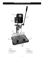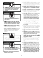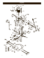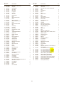
1
User Manual
Read and understand this manual before using machine.
HOLLOW CHISEL
MORTISER
Model Number
25200
®
C
US
STEEL CITY TOOL WORKS
VER. 2.07
Manual Part No. OR71593
w Steel City
ne
ur
yo
ng
si
ha
rc
pu
r
fo
THANK Y O U
designed,
en
be
s
ha
er
tis
or
m
s
hi
T
.
Hollow Chisel Mortiser
omer, in mind. When
st
cu
e
th
u,
yo
ith
w
d
te
tested, and inspec
ur mortiser will
yo
d,
ne
ai
nt
ai
m
d
an
ed
properly assembled, us
service, which is why
ee
fr
e
bl
ou
tr
of
s
ar
ye
provide you with
warranties in the
ry
ne
hi
ac
m
t
es
ng
lo
e
th
it is backed by one of
business.
products in the Steel
y
an
m
of
e
on
st
ju
is
er
This mortis
ry and is proof of
ne
hi
ac
m
ng
ki
or
dw
oo
w
City’s family of
satisfaction.
er
om
st
cu
l
ta
to
to
t
en
our commitm
cellence each and
ex
r
fo
ve
ri
st
to
ue
in
nt
co
At Steel City we
customer. For
r
ou
u,
yo
of
n
io
in
op
e
every day and value th
l City Tool Works,
ee
St
or
er
tis
or
m
ur
yo
t
comments abou
works.com .
ol
to
ty
ci
el
te
.s
w
w
w
at
te
please visit our web si
2
TABLE OF CONTENTS
INTRODUCTION
SECTION 1
Warranty .................................................................................................................................................4
SECTION 2
Product Specifications ............................................................................................................................7
SECTION 3
Accessories and Attachments ................................................................................................................7
SECTION 4
Definition of Terms ..................................................................................................................................7
SECTION 5
Feature Identification ..............................................................................................................................8
SECTION 6
General Safety........................................................................................................................................9
SECTION 7
Product Safety ......................................................................................................................................11
SECTION 8
Electrical Requirements........................................................................................................................13
SECTION 9
Unpacking & Inventory..........................................................................................................................15
SECTION 10
Assembly ..............................................................................................................................................17
SECTION 11
Adjustments ..........................................................................................................................................21
SECTION 12
Operations ............................................................................................................................................24
SECTION 13
Maintenance .........................................................................................................................................27
SECTION 14
Troubleshooting ....................................................................................................................................28
SECTION 15
Parts List...............................................................................................................................................30
INTRODUCTION
This user manual is intended for use by anyone working with this machine. It should be kept available
for immediate reference so that all operations can be performed with maximum efficiency and safety.
Do not attempt to perform maintenance or operate this machine until you have read and understand the
information contained in this manual.
The drawings, illustrations, photographs, and specifications in this user manual represent your machine
at time of print. However, changes may be made to your machine or this manual at any time with no
obligation to Steel City Tool Works.
3
WARRANTY
2 YEAR LIMITED WARRANTY
Steel City Tool Works, LLC (SCTW) warrants this SCTW machinery to be free of defects in workmanship and materials for a period
of 2 years from the date of the original retail purchase by the original owner for domestic use. Granite components are warranted for
2 years based on normal use and is void if non SCTW accessories are used that cause the break or chip. Customer must advise
SCTW within 30 days for any damage or defect found upon receipt of the product to qualify for the warranty on granite.
The warranty does not cover any product used for professional or commercial production purpose nor for industrial or educational
applications. Such cases are covered by our 1 year Limited Warranty with the Conditions and Exceptions listed below.
Conditions and exception:
Warranty applies to the original buyer only and may not be transferred. Original proof of purchase is required.
Warranty does not include failures, breakage or defects deemed after inspection by an Authorized Service Center, (ASC) or agent of,
have been directly or indirectly caused by or resulting from improper use, lack of or improper maintenance, misuse or abuse,
negligence, accidents, damage in handling or transport, or normal wear and tear of any part or component.
Additionally, warranty is void if repairs or alterations are made to the machine by an unauthorized service center without the direct
consent of SCTW
Consumables such as blades, knives, bits and sandpaper are not covered.
Wear items such as drive belt, bearings, switch, are covered for 1 year.
To file a claim of warranty or to find a service center, call toll free 877-724-8665 or email [email protected] and
you must be able to present the original or photo copy of the sales receipt including the serial number from the machine and/or carton.
SCTW will inspect, repair or replace, at its expense and its option, any part that has proven to be defective in workmanship or
material, provided that the customer returns the product prepaid to a designated ASC and provides SCTW with a reasonable
opportunity to verify the alleged defect by inspection. SCTW will return the product or replacement at our expense unless it is
determined by us that there is no defect or that the defect resulted from causes not within the scope of our warranty in which case we
will, at your direction, dispose of or return the product. In the event you choose to have the product returned, you will be responsible
for the handling and shipping costs of the return.
SCTW furnishes the above warranties in lieu of all other warranties, express or implied. SCTW shall not be liable for any special,
indirect, incidental, punitive or consequential damages, including without limitation loss of profits arising from or related to the
warranty, the breach of any agreement or warranty, or the operation or use of its machinery, including without limitation damages
arising from damage to fixtures, tools, equipment, parts or materials, direct or indirect loss caused by and other part, loss of revenue
or profits, financing or interest charges, and claims by and third person, whether or not notice of such possible damages has been
given to SCTW. Damages or any kind for any delay by or failure of SCTW to perform its obligations under this agreement or claims
made a subject of a legal proceeding against SCTW more than one (1) year after such cause of action first arose.
The validity, construction and performance of this Warranty and any sale of machinery by SCTW shall be governed by the law of the
Commonwealth of Pennsylvania, without regard to conflicts of law’s provisions of any jurisdiction. Any action related in any way to
any alleged or actual offer, acceptance or sale by SCTW or any claim related to the performance of and agreement including without
limitation this Warranty, shall take place in the federal or state courts in Allegheny County, Pennsylvania.
Warranty registration card must be submitted to SCTW for purpose of proof within 90 days of purchase with a copy of the sales
receipt. Failure to do so will, revert the 2 year warranty to 1 year as in the terms stated above. This registration is also needed to
facilitate contact in case of a safety recall.
This warranty gives you specific legal rights and you may have other rights which vary in certain States or Provinces.
Note to user
This instruction manual is meant to serve as a guide only. Specification and references are subject to change without prior notice.
Check the website www.steelcitytoolworks.com for updated manuals with reference to the VER# located on the front page.
LIMITED WARRANTY – ACCU-SHOP line of bench top tools
Steel City Tool Works, LLC (SCTW) warrants this SCTW ACCU-SHOP machinery to be free of defects in workmanship and materials
for a period of 2 years from the date of the original retail purchase by the original owner for domestic use.
Consumables such as blades, knives, bits and sandpaper are not covered.
Wear items such as drive belt, bearings, switch, are covered for 1 year.
The warranty does not cover any product used for professional or commercial production purpose nor for industrial or educational
applications. Such cases are covered by our 30 days Limited Warranty with the Conditions and Exceptions listed previously.
4
WARRANTY CARD
Name ________________________________________________
Street _______________________________________________
Apt. No. ______________________________________________
City _________________________ State ______ Zip __________
Phone Number_________________________________________
E-Mail ________________________________________________
NOTE: The Proof of Purchase must be submitted along with this
card in order to have the Warranty to take into effect. Fail to submit
the Proof of Purchase may invalidate your Product Warranty.
The following information is given on a voluntary basis
and is strictly confidential.
Where did you purchase your STEEL CITY machine?
Store: ____________________________________________
City:______________________________________________ Online: ______________________________________________
2.
How did you first learn of Steel City Tool Works?
___ Advertisement
___ Mail Order Catalog
___ Web Site
___ Friend
___ Local Store
Other_______________________
CUT HERE
3.
4.
5.
6.
7.
Which of the following magazines
___ American Woodworker
___ Canadian Woodworking
___ Fine Homebuilding
___ Journal of Light Construction
___ Popular Mechanics
___ Popular Woodworking
___ WOOD
___ WOODEN Boat
___ Woodsmith
___ Woodworker
___ Workbench
What is your age group?
___ 20 to 29 years
___ 40 to 49 years
___ 60 to 69 years
9.
How many Steel City machines do you own? _____________
11. Which benchtop tools do you own? Check all that apply.
___ Belt Sander
___ Belt / Disc Sander
___ Drill Press
___ Band Saw
___ Grinder
___ Mini Jointer
___ Mini Lathe
___ Scroll Saw
___ Spindle / Belt Sander
Other______________________
do you subscribe to?
___ Cabinetmaker
___ Family Handyman
___ Fine Woodworking
___ Old House Journal
___ Popular Science
___ Today’s Homeowner
___ Woodcraft
___ Woodshop News
___ Woodwork
___ Woodworker’s Journal
Other_________________
12. Which portable / hand held power tools do you own?
Check all that apply.
___ Biscuit Jointer
___ Belt Sander
___ Dust Collector
___ Circular Saw
___ Detail Sander
___ Drill / Driver
___ Miter Saw
___ Orbital Sander
___ Palm Sander
___ Portable Thickness Planer
___ Saber Saw
___ Reciprocating Saw
___ Router
Other_______________________
13. What machines / accessories would you like to see added to the
STEEL CITY line?
____________________________________________________
____________________________________________________
Which of the following woodworking / remodeling shows do
you watch?
___ Backyard America ___ The American Woodworker
___ Home Time
___ The New Yankee Workshop
___ This Old House
___ Woodwright’s Shop
Other__________________________________________
What is your annual household
___ $20,000 to $29,999
___ $40,000 to $49,999
___ $60,000 to $69,999
___ $80,000 to $89,999
How would you rank your woodworking skills?
___ Simple
___ Intermediate
___ Advance
___ Master Craftsman
10. What stationary woodworking tools do you own?
Check all that apply.
___ Air Compressor
___ Band Saw
___ Drill Press
___ Drum Sander
___ Dust Collection
___ Horizontal Boring Machine
___ Jointer
___ Lathe
___ Mortiser
___ Panel Saw
___ Planer
___ Power Feeder
___ Radial Arm Saw
___ Shaper
___ Spindle Sander
___ Table Saw
___ Vacuum Veneer Press
___ Wide Belt Sander
Other____________________________________________
Product Description:_____________________________________
Model No.: _________________ Serial No.: _________________
1.
8.
14. What new accessories would you like to see added?
____________________________________________________
____________________________________________________
income?
___ $30,000 to $39,999
___ $50,000 to $59,999
___ 70,000 to $79,999
___ $90,000 +
15. Do you think your purchase represents good value?
___Yes
___ No
16. Would you recommend STEEL CITY products to a friend?
___ Yes
___ No
___ 30 to 39 years
___ 50 to 59 years
17. Comments:
____________________________________________________
____________________________________________________
____________________________________________________
____________________________________________________
____________________________________________________
___ 70 + years
How long have you been a woodworker?
___ 0 to 2 years
___ 2 to 8 years
___ 8 to 20 years
___ over 20 years
5
FOLD ON DOTTED LINE
PLACE
STAMP
HER E
SteelCityToolWorks
#4 Northpoint Court
Bolingbrook, IL 60440
FOLD ON DOTTED LINE
6
PRODUCT SPECIFICATIONS
MOTOR
PRODUCT DIMENSIONS
Type
Induction
Maximum stroke
5”
Continuous duty HP
1/2 HP
Chisel center to fence
4”
Amps
5.6
Under hold down
1” x 4-1/4”
Volts
120
Fence size
14-1/2”x 3”
Hertz
60
Base size (without extensions)
17”x 15”
Base size (with extensions)
17” x 35”
RPM
1725 RPM
Chuck type
Keyed
Chuck maximum capacity
3/8”
Chisel sizes
1/4”x 1/4”
5/16”x 5/16”
3/8”x 3/8”
1/2”x 1/2”
OVERALL DIMENSIONS
Height
30-1/2”
Width
15”
Depth
17”
Weight
81 lbs.
Micro-adjust
Yes
Bit holder
Yes
SHIPPING DIMENSIONS
Handle position
Left or right
(interchangeable)
Carton type
Box
Length
19-3/4”
Width
16-1/2”
Height
17-1/2”
Gross weight
88 lbs.
ACCESSORIES AND ATTACHMENTS
There are a variety of accessories available for your Steel City Product. For more information on
any accessories associated with this and other machines, please contact your nearest Steel City
distributor, or visit our website at: www.steelcitytoolworks.com.
DEFINITION OF TERMS
Blind Mortise - Joint where the mortise does not go all
the way through the stock.
Micro Adjust - Assembly which allows the fence to be
moved in or out in very small increments.
Chipout - Breakage on the exit side of a through
mortise.
Tenon - A projection on the end of a workpiece that is
inserted into a mortise.
Corner Mortise - Commonly used for frame and panel
sections such as raised panel cabinet doors.
Through Mortise - Joint where the mortise goes completely through the workpiece, allowing the end of the
tenon to be exposed.
7
FEATURE IDENTIFICATION
B
C
A
E
F
G
H
D
A) Switch
E) Fence
B) Motor housing
F) Hold down
C) Raise/Lower handle
G) Base/Worktable
D) Stock rollers
H) Extension wings
8
GENERAL SAFETY
!
WARNING
!
WARNING
TO AVOID serious injury and damage to the machine,
read and follow all Safety and Operating Instructions
before assembling and operating this machine.
This manual is not totally comprehensive. It does not
and can not convey every possible safety and operational problem which may arise while using this
machine. The manual will cover many of the basic and
specific safety procedures needed in an industrial environment.
Exposure to the dust created by power sanding, sawing, grinding, drilling and other construction activities
may cause serious and permanent respiratory or
other injury, including silicosis (a serious lung disease), cancer, and death. Avoid breathing the dust,
and avoid prolonged contact with dust. The dust
may contain chemicals known to the State of
California to cause cancer, birth defects or other
reproductive harm.
All federal and state laws and any regulations having
jurisdiction covering the safety requirements for use of
this machine take precedence over the statements in
this manual. Users of this machine must adhere to all
such regulations.
Some examples of these chemicals are:
• Lead from lead-based paints.
• Crystalline silica from bricks, cement and other
masonry products.
• Arsenic and chromium from chemically-treated
lumber.
Below is a list of symbols that are used to attract your
attention to possible dangerous conditions.
!
This is the international safety alert symbol. It is used
to alert you to potential personal injury hazards. Obey
all safety messages that follow this symbol to avoid
possible injury or death.
!
Always operate tool in well ventilated area and provide for proper dust removal. Use a dust collection
system along with an air filtration system whenever
possible. Always use properly fitting NIOSH/OSHA
approved respiratory protection appropriate for the
dust exposure, and wash exposed areas with soap
and water.
DANGER
Indicates an imminently hazardous situation which, if
not avoided, WILL result in death or serious injury.
!
1. To avoid serious injury and damage to the machine,
read the entire User Manual before assembly and
operation of this machine.
WARNING
Indicates a potentially hazardous situation which, if not
avoided, COULD result in death or serious injury.
!
CAUTION
!
WARNING
Indicates a potentially hazardous situation, if not avoided, MAY result in minor or moderate injury. It may also
be used to alert against unsafe practices.
2. ALWAYS wear eye protection. Any machine can
throw debris into the eyes during operations,
which could cause severe and permanent eye
damage. Everyday eyeglasses are NOT safety
glasses. ALWAYS wear Safety Goggles (that
comply with ANSI standard Z87.1) when operating power tools.
CAUTION
CAUTION used without the safety alert symbol indicates a potentially hazardous situation which, if not
avoided, may result in property damage.
NOTICE
This symbol is used to alert the user to useful information about proper operation of the machine.
9
!
11. DO NOT FORCE the machine to perform an operation for which it was not designed. It will do a safer
and higher quality job by only performing operations
for which the machine was intended.
WARNING
12. DO NOT stand on a machine. Serious injury could
result if it tips over or you accidentally contact any
moving part.
3. ALWAYS wear hearing protection. Plain cotton is
not an acceptable protective device. Hearing
equipment should comply with ANSI S3.19
Standards.
!
13. DO NOT store anything above or near the machine.
14. DO NOT operate any machine or tool if under the
influence of drugs, alcohol, or medication.
WARNING
15. EACH AND EVERY time, check for damaged parts
prior to using any machine. Carefully check all
guards to see that they operate properly, are not
damaged, and perform their intended functions.
Check for alignment, binding or breakage of all
moving parts. Any guard or other part that is damaged should be immediately repaired or replaced.
4. ALWAYS wear a NIOSH/OSHA approved dust
mask to prevent inhaling dangerous dust or airborne particles.
16. Ground all machines. If any machine is supplied
with a 3-prong plug, it must be plugged into a 3contact electrical receptacle. The third prong is
used to ground the tool and provide protection
against accidental electric shock. DO NOT remove
the third prong.
5. ALWAYS keep the work area clean, well lit, and
organized. DO NOT work in an area that has slippery floor surfaces from debris, grease, and wax.
6. ALWAYS unplug the machine from the electrical
receptacle before making adjustments, changing
parts or performing any maintenance.
17. Keep visitors and children away from any machine.
DO NOT permit people to be in the immediate work
area, especially when the machine is operating.
7. AVOID ACCIDENTAL STARTING. Make sure that
the power switch is in the “OFF” position before
plugging in the power cord to the electrical
receptacle.
!
18. KEEP protective guards in place and in working
order.
19. MAINTAIN your balance. DO NOT extend yourself
over the tool. Wear oil resistant rubber soled shoes.
Keep floor clear of debris, grease, and wax.
WARNING
20. MAINTAIN all machines with care. ALWAYS KEEP
machine clean and in good working order. KEEP all
blades and tool bits sharp.
21. NEVER leave a machine running, unattended. Turn
the power switch to the OFF position. DO NOT
leave the machine until it has come to a complete
stop.
8. AVOID a dangerous working environment. DO
NOT use electrical tools in a damp environment
or expose them to rain or moisture.
!
22. REMOVE ALL MAINTENANCE TOOLS from the
immediate area prior to turning the machine ON.
WARNING
23. SECURE all work. When it is possible, use clamps
or jigs to secure the workpiece. This is safer than
attempting to hold the workpiece with your hands.
9. CHILDPROOF THE WORKSHOP AREA by
removing switch keys, unplugging tools from the
electrical receptacles, and using padlocks.
24. STAY ALERT, watch what you are doing, and use
common sense when operating any machine. DO
NOT operate any machine tool while tired or under
the influence of drugs, alcohol, or medication. A
moment of inattention while operating power tools
may result in serious personal injury.
10. DO NOT use electrical tools in the presence of
flammable liquids or gasses.
10
25. USE ONLY recommended accessories. Use of
incorrect or improper accessories could cause serious injury to the operator and cause damage to the
machine. If in doubt, DO NOT use it.
28. Information regarding the safe and proper operation
of this tool is also available from the following
sources:
Power Tool Institute
1300 Summer Avenue
Cleveland, OH 44115-2851
www.powertoolinstitute.org
26. Wear proper clothing, DO NOT wear loose clothing,
gloves, neckties, or jewelry. These items can get
caught in the machine during operations and pull
the operator into the moving parts. Users must
wear a protective cover on their hair, if the hair is
long, to prevent it from contacting any moving parts.
National Safety Council
1121 Spring Lake Drive
Itasca, IL 60143-3201
27. SAVE these instructions and refer to them frequently and use them to instruct other users.
American National Standards Institute
25West 43rd. St, 4th Floor
New York, NY. 10036
ANSI 01.1 Safety Requirements
For Woodworking Machines
WWW.ANSI.ORG
U.S. Department of Labor Regulations
OSHA 1910.213 Regulations
WWW.OSHA.GOV
PRODUCT SAFETY
6. Safety decals are on this machine to warn and
direct you to how to protect yourself or visitors from
personal injury. These decals MUST be maintained
so that they are legible. REPLACE decals that are
not legible.
1. Serious personal injury may occur if normal safety
precautions are overlooked or ignored. Accidents
are frequently caused by lack of familiarity or failure
to pay attention. Obtain advice from supervisor,
instructor, or another qualified individual who is
familiar with this machine and its operations.
7. DO NOT leave the unit plugged into the electrical
outlet. Unplug the unit from the outlet when not in
use and before servicing, performing maintenance
tasks, or cleaning.
2. Every work area is different. Always consider safety first, as it applies to your work area. Use this
machine with respect and caution. Failure to do so
could result in serious personal injury and damage
to the machine.
8. ALWAYS turn the power switch “OFF” before
unplugging the mortiser.
3. Prevent electrical shock. Follow all electrical and
safety codes, including the National Electrical Code
(NEC) and the Occupational Safety and Health
Regulations (OSHA). All electrical connections and
wiring should be made by qualified personnel only.
!
!
WARNING
WARNING
9. DO NOT handle the plug or mortiser with
wet hands.
10. USE accessories only recommended by Steel City.
4. TO REDUCE the risk of electrical shock. DO
NOT use this machine outdoors. DO NOT
expose to rain or moisture. Store indoors in a
dry area.
11. DO NOT pull the mortiser by the power cord.
NEVER allow the power cord to come in contact
with sharp edges, hot surfaces, oil or grease.
12. DO NOT unplug the mortiser by pulling on the
power cord. ALWAYS grasp the plug, not the cord.
5. STOP using this machine, if at any time you experience difficulties in performing any operation.
Contact your supervisor, instructor or machine service center immediately.
13. REPLACE a damaged cord immediately. DO NOT
use a damaged cord or plug. DO NOT USE if the
mortiser is not operating properly, or has been damaged, left outdoors or has been in contact with
water.
11
14. DO NOT use the mortiser as a toy. DO NOT use
near or around children.
26. DO NOT attempt to mortise material that does not
have a flat surface, unless a suitable support is
used.
15. ALWAYS WEAR EYE PROTECTION. Any power
tool can throw debris into the eyes during operations, which could cause severe and permanent
eye damage. Everyday eyeglasses are NOT safety
glasses. ALWAYS wear Safety Goggles (that comply with ANSI standard Z87.1) when operating
power tools.
27. USE ONLY DRILL BITS, CUTTING TOOLS, OR
OTHER ACCESSORIES with shank size recommended in your instruction manual. The wrong size
accessory can cause damage to the machine
and/or serious injury.
28. USE ONLY DRILL BITS OR CUTTING TOOLS
that are not damaged. Damaged items can cause
malfunctions that lead to injuries.
16. Basic precautions should ALWAYS be followed
when using any power tool.
17. DO NOT OPERATE THIS MACHINE until it is
assembled and installed according to the instructions.
29. ALWAYS position the hold-down directly over the
workpiece to prevent the workpiece from lifting
during operation. Loss of control of the workpiece
can cause serious injury.
18. OBTAIN ADVICE FROM YOUR SUPERVISOR,
instructor, or another qualified person if you are not
familiar with the operations of this power tool.
30. TURN THE MACHINE “OFF” AND WAIT FOR
THE DRILL BIT AND CUTTING TOOL TO STOP
TURNING prior to cleaning the work area, removing
debris, or removing or securing work-piece. A moving drill bit or cutting tool can cause serious injury.
19. DO NOT leave any power tool plugged into the
electrical outlet. Unplug it from the outlet when not
in use and before servicing and cleaning.
31. PROPERLY SUPPORT LONG OR WIDE workpieces, loss of control of the workpiece can cause
severe injury.
20. TO REDUCE THE RISK OF ELECTRICAL
SHOCK, do not use outdoors. Do not expose to
rain. Store indoors.
32. NEVER PERFORM LAYOUT, ASSEMBLY OR
SET-UP WORK on the table/work area when the
machine is running. Serious injury can result.
21. FOLLOW all electrical and safety codes, including
the National Electric Code (NEC) and the Occupational Safety and Health Regulations (OSHA).
All electrical connections and wiring should be
made by qualified personnel only.
33. TURN THE MACHINE “OFF”, disconnect the
machine from the power source, and clean the
table/work area before leaving the machine.
22. CONNECT power tool to a properly grounded outlet
only. See grounding instructions.
34. REPLACE a damaged cord immediately. DO NOT
use a damaged cord or plug. If the power tool is not
operating properly, or has been damaged, left outdoors or has been in contact with water, return it to
a Steel City Service Center.
23. SECURE THE MACHINE TO A SUPPORTING
SURFACE. Vibration can cause the machine to
slide, walk, or tip over.
24. NEVER START THE MACHINE with the drill bit or
cutting tool against the workpiece. Loss of control of
the workpiece can cause serious injury.
35. SAVE THESE INSTRUCTIONS. Refer to them frequently and use them to instruct other users.
25. PROPERLY LOCK THE DRILL BIT OR CUTTING
TOOL IN THE UNIT before operating this machine.
12
ELECTRICAL REQUIREMENTS
TO PREVENT electrical shock, follow all electrical and
safety codes, including the National Electrical Code
(NEC) and the Occupational Safety and Health
Regulations (OSHA). All electrical connections and
wiring should be made by qualified personnel only.
DO NOT connect the machine to the power source
before you have completed the set up process.
TO REDUCE the risk of electrical shock, DO NOT use
machine outdoors. DO NOT expose to rain or moisture. Store indoors in a dry area.
This motor in this machine is designed to run at 115V.
DO NOT connect the machine to the power source until
instructed to do so.
GROUNDING INSTRUCTIONS
!
PLUGS/RECEPTACLES
WARNING
!
WARNING
This machine MUST BE GROUNDED while in use to
protect the operator from electric shock.
• Electrocution or fire could result if this machine is
not grounded properly or if the electrical configuration does not comply with local and state electrical
codes.
In the event of a malfunction or breakdown, GROUNDING provides the path of least resistance for electric
current and reduces the risk of electric shock. This
machine is equipped with an electric cord that has an
equipment-grounding conductor and a grounding plug.
The plug MUST be plugged into a matching electrical
receptacle that is properly installed and grounded in
accordance with ALL local codes and ordinances.
• MAKE CERTAIN the machine is disconnected
from power source before starting any electrical|
work.
• MAKE SURE the circuit breaker does not exceed
the rating of the plug and receptacle.
If a plug is provided with your machine DO NOT modify
the plug. If it will not fit your electrical receptacle, have
a qualified electrician install the proper connections to
meet all electrical codes local and state. All connections
must also adhere to all of OSHA mandates.
The motor supplied with your machine is a 115 volt
motor. It is shipped wired for 115 volt application. Never
connect the green or ground wire to a live terminal.
This tool is intended for use on a circuit that has an
electrical receptacle as shown in Figure 1-1. Figure 1-1
shows a NEMA approved 3-wire, 15 amp electrical plug
and receptacle that have a grounding conductor. If a
properly grounded electrical receptacle is not available,
an adapter as shown in Figure 1-2 can be used to temporarily connect this plug to a 2-contact ungrounded
receptacle. The adapter has a rigid lug extending from it
that MUST be connected to a permanent earth ground,
such as a properly grounded receptacle box. THIS
ADAPTER IS PROHIBITED IN CANADA.
IMPROPER ELECTRICAL CONNECTION of the equipment-grounding conductor can result in risk of electric
shock. The conductor with the green insulation (with or
without yellow stripes) is the equipment-grounding conductor. DO NOT connect the equipment-grounding
conductor to a live terminal.
Check with a qualified electrician or service personnel if
you do not completely understand the grounding
instructions, or if you are not sure the tool is properly
grounded.
13
EXTENSION CORDS
Fig. 1-1
!
WARNING
To reduce the risk of fire or electrical shock, use the
proper gauge of extension cord. When using an
extension cord, be sure to use one heavy enough to
carry the current your machine will draw.
The smaller the gauge-number, the larger the diameter
of the extension cord is. If in doubt of the proper size of
an extension cord, use a shorter and thicker cord. An
undersized cord will cause a drop in line voltage resulting in a loss of power and overheating.
Fig. 1-2
!
CAUTION
USE ONLY a 3-wire extension cord that has a 3-prong
grounding plug and a 3-pole receptacle that accepts the
machine’s plug.
If you are using an extension cord outdoors, be sure
it is marked with the suffix “W-A” (“W” in Canada) to
indicate that it is acceptable for outdoor use.
Make certain the extension cord is properly sized, and
in good electrical condition. Always replace a worn or
damaged extension cord immediately or have it
repaired by a qualified person before using it.
Protect your extension cords from sharp objects, excessive heat, and damp or wet areas.
MINIMUM RECOMMENDED GAUGE FOR EXTENSION CORDS (AWG)
115 VOLT OPERATION ONLY
14
25’ LONG
50’ LONG
100’ LONG
0 to 6 Amps
18 AWG
16 AWG
16 AWG
6 to 10 Amps
18 AWG
16 AWG
Not recommended
10 to 12 Amps
16 AWG
16 AWG
Not recommended
UNPACKING & INVENTORY
Remove all of the parts from the shipping box and lay
them on a clean work surface. Compare the items to
inventory figures and verify that all items are accounted
for before discarding the shipping box.
CHECKING CONTENTS
This mortiser will require some amount of assembly.
Remove all protective materials and coatings from the
parts. The protective coatings can be removed by
spraying WD-40 on a part and wiping it off with a soft
cloth. This may need to be redone several times before
all of the protective coatings are removed completely.
!
WARNING
To avoid serious injury, do not attempt to plug in the
power cord and turn “ON” the mortiser if any parts are
missing. The mortiser should only be turned “ON” after
all the parts have been obtained and installed correctly.
For missing parts, contact Steel City at 1-877-SC4TOOL.
CAUTION: DO NOT use acetone, gasoline or lacquer
thinner to remove any protective coatings.
After cleaning, apply a good quality paste wax to any
unpainted surfaces. Make sure to buff out the wax
before assembly.
A
B
D
C
A) Mortiser
B) Base
C) Extension Wings (2)
D) Stabilizer
15
J
L
I
H
E
K
F
G
M
O
T
P
Q
N
S
U
R
V
E) Hex wrench (2)
N) Fence lock handle
F) Depth stop rod
O) M5 x 12mm pan head screw (2)
G) M8 x 35mm hex socket head screw (4)
P) M5 flat washer (2)
H) M8 lock washer (4)
Q) Chisel holder
I)
R) Stock rollers
M8 flat washer (4)
J) M12 Handle lock nut
S) Holddown
K) Handle spring
T) Chuck key
L) Handle
U) Guide rod
M) M12 flat washer (2)
V) Fence
16
ASSEMBLY
!
BASE ASSEMBLY
! WARNING
WARNING
1. DO NOT assemble the Mortiser until you are sure
the tool is disconnected from the power source.
MAKE CERTAIN THAT THE MORTISER IS DISCONNECTED FROM THE POWER SOURCE.
2. DO NOT assemble the Mortiser until you are sure
the power switch is in the off position.
1. Place mortiser column (A) over the base (B), aligning the four holes in the mortiser column with the
four holes in the base. SEE FIG. 6.
HYDRAULIC CYLINDER ASSEMBLY
!
Fig. 6
WARNING
MAKE CERTAIN THAT THE MORTISER IS DISCONNECTED FROM THE POWER SOURCE.
A
1. Thread lower ball stud fitting into hole (B) in the
column of the Mortiser. SEE FIG. 5
Fig. 5
C
B
2. Insert four M8 socket head cap screws (C) with
washers and lockwashers through the column.
Thread into base and tighten.
FENCE ASSEMBLY
A
!
WARNING
MAKE CERTAIN THAT THE MORTISER IS DISCONNECTED FROM THE POWER SOURCE.
1. Insert guide rod (A) through hole in hold down (B)
and tighten set screw (C) using supplied hex
wrench. SEE FIG. 8.
C
Fig. 8
C
B
B
E
2. Snap the hydraulic cylinder (C) over the upper ball
stud fitting (A) on the back of the Mortiser head.
A
D
3. Attach the other end of the hydraulic cylinder to the
lower ball stud fitting installed in step 1.
F
17
2. Insert guide rod into hole (D) of fence assembly (E)
and tighten set screw (F) using supplied hex
wrench.
RAISING/LOWERING HANDLE
!
3. Insert fence guide shaft (G) through hole (H) in
column of the mortiser. SEE FIG. 9.
WARNING
MAKE CERTAIN THAT THE MORTISER IS DISCONNECTED FROM THE POWER SOURCE.
Fig. 9
1. Line up the notches in the hub on the handle (A)
with the slots in the gear shaft (B). SEE FIG. 11.
Fig. 11
H
G
B
4. Thread fence lock handle (I) into the column of the
mortiser. Place flat washer over the shaft and
secure with phillips head screw. Tighten to secure
fence. SEE FIG. 10.
A
NOTE: The handle may be attached to either the left
side or the right side, depending on your preference.
Fig. 10
2. Insert handle (C) with flat washer (G) installed
through the hub (D). Place spring (E) over the
handle. Place the second flat washer (H) on the
handle and thread hex nut (F) onto the handle.
SEE FIG. 12.
Fig. 12
C
I
G
D
NOTE: Fence lock handle is spring loaded and can be
repositioned by pulling out on the handle and rotating it.
H
E
F
NOTE: The handle is spring loaded. You can reposition
it by pulling it out and repositioning it on the gear shaft.
18
TOOL AND CHISEL HOLDER
!
INSTALLING CHISEL AND BIT
WARNING
!
WARNING
MAKE CERTAIN THAT THE MORTISER IS DISCONNECTED FROM THE POWER SOURCE.
MAKE CERTAIN THAT THE MORTISER IS DISCONNECTED FROM THE POWER SOURCE.
CHISELS ARE VERY SHARP AND CAN CAUSE A
SERIOUS CUT. TAKE EXTREME CAUTION WHEN
HANDLING CHISELS.
Place tool and chisel holder (A) on top of column (B)
and align with mounting holes. Using two screws and
two washers provided, tighten holder to top of
column. SEE FIG. 13.
1. Insert bit (A) into chisel (B). SEE FIG. 15.
Fig. 13
Fig. 15
A
B
A
B
2. Loosen set screw (C) and push chisel (D) up
through hole in head (E) as far as possible, making
sure that the opening in the chisel (F) is facing left
or right. SEE FIG. 16.
FASTENING MACHINE TO
SUPPORTING SURFACE
!
WARNING
Fig. 16
MAKE CERTAIN THAT THE MORTISER IS DISCONNECTED FROM THE POWER SOURCE.
If during operation there is any tendency for the mortiser
to tip over, slide, or walk on the supporting surface, the
base must be secured to the supporting surface with
fasteners (not supplied), through the two holes (A)
located in the mortiser base. SEE FIG. 14.
Fig. 14
A
C
E
D
F
19
3. Lower chisel 1/16” to 3/16” and tighten set screw.
There must be a space of 1/16” to 3/16” clearance
(G), about the thickness of a dime, between the
bushing (H) and shoulder of chisel (I). This assures
having proper clearance between the cutting edges
of the bit and points of the chisel after the bit is
inserted into the chuck. SEE FIG. 17.
5. Loosen set screw (L), push chisel (M) up against
the bottom of bushing (N) and tighten set screw.
This should provide the proper distance between
the cutting edges of the bit and points of the chisel.
SEE FIG. 19.
Fig. 19
Fig. 17
L
H
G
N
I
M
4. Push bit (J) up through the chisel and into the
chuck (K) until the bottom of the bit is flush with the
bottom of the chisel. Lock bit into the chuck using
the supplied chuck key. SEE FIG. 18.
6. The flat portion of the bit (O) should now be adjusted to a minimum of 1/16” below the bottom of the
chisel (P). For certain types of wood it may be necessary to increase this distance to a maximum of
3/16” clearance. SEE FIG. 20.
Fig. 18
Fig. 20
K
J
P
O
20
ADJUSTMENTS
DEPTH STOP ROD
FENCE
The depth stop rod is provided to limit the cutting depth
of the chisel. To adjust the depth stop rod (A), loosen
set screw (B). SEE FIG. 23.
The fence can be moved in or out to accommodate various size workpieces.
To move fence:
Fig. 23
1. Loosen fence lock handle (A) until the fence glide
shaft (B) can move freely. SEE FIG. 25.
2
A
Slide fence (C) in or out to the desired position.
3. Tighten fence lock handle to secure fence.
Fig. 25
C
A
B
B
1. Lower head until the cutting chisel (C) is at the
desired depth. SEE FIG. 24.
D
Fig. 24
MICRO-ADJUST ASSEMBLY
Sometimes it is necessary to move the fence in small
increments. When this is the case, the micro-adjust
assembly should be used.
E
1
Loosen the fence lock handle (A) so that the fence
(C) may slide smoothly. SEE FIG. 25.
2. Rotate the adjustment knob (D) clockwise to move
the fence in towards the mortiser column. Rotate
counterclockwise to move the fence away from the
mortiser column.
D
C
2. Lower depth stop rod until it contacts the top of the
column (D).
3. Tighten set screw (E).
21
Fig. 27
HOLDDOWN
The purpose of the holddown is to prevent the workpiece from lifting as the chisel is raised up.
To adjust: Loosen set screw (A), position holddown (B)
until it just touches the top of the workpiece (C) and
allows the workpiece to slide left or right. Once holddown is in position, retighten set screw. SEE FIG. 26.
C
NOTE: The holddown can also be turned upside down
to accommodate thicker workpieces. When doing this,
tighten the set screw on the back side of the holddown.
SEE FIG. 26.
B
Fig. 26
A
SLIDING FIT BETWEEN
HEAD AND COLUMN
A dovetail gib is provided on the rear of the head to
insure a good sliding fit between the head and the
column when the head is raised and lowered. This
should be set at the factory and should not need
adjustment. If adjustment is necessary, perform the
following steps.
A
1. Loosen two socket head cap screws (A) in the
dovetail gib (B) only slightly (less than 1/8 turn)
using provided hex wrench. SEE FIG. 28.
B
Fig. 28
C
SETTING CHISEL
SQUARE TO FENCE
C
!
B
A
WARNING
MAKE CERTAIN THAT THE MORTISER IS DISCONNECTED FROM THE POWER SOURCE.
Checking that chisel is square to fence:
1. Place a square against the face of the fence (A).
SEE FIG. 27.
2. Turn adjusting screws (C) clockwise to make a
tighter fit, turn counterclockwise for a looser fit.
2. Check to see if left side of chisel (B) is square to
the face of the fence.
NOTE: Correct adjustment is when a good snug sliding
fit is obtained without any side movement between the
gib and the column. This adjustment should not be too
tight that it restricts the sliding movement or too loose
that it affects accuracy.
3.
4.
If not square, loosen set screw (C) and reposition
chisel until the left side of the chisel is flat against
the square.
3. Once proper fit is achieved, retighten the two
socket head cap screws.
Retighten set screw.
22
ROTATING COLUMN 180 DEGREES
USING BITS WITH
EXTRA LONG SHANKS
Sometimes a workpiece may be too large to fit between
the base and the chisel. When this is the case, you
can rotate the column of the mortiser 180 degrees, as
shown, and perform the work off of a bench or floor.
When using bits with extra long shanks, it will be necessary to remove the extension.
!
Fig. 29
WARNING
MAKE CERTAIN THAT THE MORTISER IS DISCONNECTED FROM THE POWER SOURCE.
Fig. 30
A
B
B
A
C
!
WARNING
When rotating column 180 Degrees, you MUST fasten
the machine to a supporting surface. See FASTENING
MACHINE TO SUPPORTING SURFACE in the
ADJUSTMENTS section of this manual.
1. To rotate the column, remove the four M8 socket
head cap screws (C) that bolt the mortiser column
(A) to the base (B). SEE FIG. 29.
2. Rotate column 180 degrees.
1. Remove the mortising bit.
3. Replace four M8 socket head cap screws (C).
2. Place one open end wrench on the flats of the
extension (A) and one open end wrench on the flats
of the motor shaft (B) (wrenches not supplied).
3. Unscrew the extension and chuck from the motor
shaft.
4. Remove the chuck from the extension.
5. Reinstall the chuck to the motor shaft. Tighten
securely.
23
OPERATIONS
!
When the tool is not in use, the tool should be locked in
the OFF position to prevent unauthorized use. This can
be done by placing a padlock (not provided) through the
hole in the green button.
WARNING
MAKE CERTAIN THAT THE MORTISER IS DISCONNECTED FROM THE POWER SOURCE.
!
WARNING
RAISING AND
LOWERING THE HEAD
The head is raised and lowered by using the handle.
For maximum leverage during the mortising operation,
the handle can be repositioned by pulling out the hub
(A) of the handle assembly and repositioning hub on
the pinion shaft (B). SEE FIG. 32.
ALWAYS wear eye protection. Any machine can
throw debris into the eyes during operations, which
could cause severe and permanent eye damage.
Everyday eyeglasses are NOT safety glasses.
ALWAYS wear Safety Goggles (that comply with
ANSI standard Z87.1) when operating power tools.
!
Fig. 32
WARNING
ALWAYS wear a NIOSH/OSHA approved dust mask
to prevent inhaling dangerous dust or airborne
particles.
B
ON/OFF SWITCH
The switch is located on the side of the motor. To turn
the machine on, push the green button (A). To turn the
machine off, push the red button (B). SEE FIG. 31.
A
Fig. 31
A
B
24
EXTENSION WINGS
USING AUXILIARY WOOD FENCE
The mortiser base (A) is equipped with two extension
wings (B), one on each side of base. They are used
when working with longer workpieces, to add stability
to the operation. SEE FIG. 33.
When mortising an extra high workpiece, an auxiliary
fence can be fastened to the fence with wood screws
(not provided) through the holes in the fence. This
provides additional support for the workpiece during
mortising operation.
Fig. 33
A
USING SACRIFICIAL BOARD
B
B
When performing a through mortise, it is a good practice to use a sacrificial board to prevent any chipout at
the bottom of the mortise.
1. To attach a sacrificial board, place sacrificial board
(A) against the face of the fence (B). SEE FIG. 34.
Fig. 34
STOCK ROLLERS
The stock rollers are a convenience feature that helps
keep the workpiece pressed firmly against the fence.
To set up:
1. Press workpiece (A) firmly up against the fence (B).
SEE FIG. 33A.
C
B
Fig. 33A
C
B
A
D
E
A
D
C
2. Loosen stock rollers (C) by turning each knob (D)
counterclockwise.
2. Attach sacrificial board to fence using wood screws
(not provided) though the holes of the fence (C).
3. Slide the stock rollers so that they are pressed
firmly up against the workpiece.
3. Place workpiece (D) on top of sacrificial board and
up against the fence.
4. Tighten the knobs on the stock rollers by turning
them clockwise.
4. Fasten workpiece using the holddown (E).
NOTE: Make sure that the rollers are pressed against
the workpiece firmly enough to keep it from pulling
away from the fence, but not so tight that the workpiece
cannot slide freely from left to right.
NOTE: When using sacrificial board, DO NOT use the
stock rollers.
25
OPERATING THE MORTISER
3. When making additional penetrations, leave a gap
between the holes. SEE FIG. 36.
1. Make sure that the workpiece (A) is held firmly
against the fence (B) when cutting and that the
holddown (C) is properly adjusted. SEE FIG. 35.
Fig. 36
Fig. 35
D
B
A
C
4. Once the desired length of the mortise is achieved,
go back and chisel out the remaining gaps. This
will ensure a smooth, clean mortise. SEE FIG. 37.
Fig. 37
2. Using the Raise/Lower handle (D), lower the chisel
until it penetrates the workpiece.
NOTE: The rate of penetration of the chisel must be
fast enough to prevent burning at the tip of the bit, but
not too fast as to stall the motor.
NOTE: You may encounter smoke from the bit or
material once the chisel has engaged the material.
The smoke created is a natural operating occurrence in
hollow chisel mortising and is caused by material chip
friction and the resins in the stock being burned off.
NOTE: Retract drill bit frequently during drilling operations to help clear chips from the hole.
NOTE: A blue-tinted chisel is not indicative of a dull
chisel, but a combination of friction and resin buildup
on the cutting faces of the chisel. A dull chisel can be
detected by the amount of excess force required to
complete a cut.
26
MAINTENANCE
Repairs to this power tool should be performed by
trained personnel only. Contact your nearest Steel City
Service Center for authorized service. Unauthorized
repairs or replacement with non-factory parts could
cause serious injury to the operator and damage to
your machine.
!
PROTECTING CAST IRON TABLE
FROM RUST
!
WARNING
MAKE CERTAIN to turn the switch "OFF" and unplug
the power cord from its power source.
WARNING
The environment and frequency of human contact can
have a very detrimental impact on unpainted cast iron
surfaces. Moisture, humidity and oils (from human
hands!) can cause the unpainted cast iron surfaces to
mar or rust, so it is important to conduct routine maintenance to keep your mortiser looking new. Cleaning
and waxing the cast iron surfaces on a regular maintenance schedule is recommended as follows:
To prevent injury to yourself or damage to the machine,
turn the switch to the “OFF” position and unplug the
power cord from the electrical receptacle before making
any adjustments.
The Mortiser will operate best if it is kept in proper
operating condition. Keep unit adjusted as described in
OPERATIONS AND ADJUSTMENTS.
To clean and maintain the unpainted cast iron surfaces:
• Turn the power switch “OFF” and unplug the power
cord from its power source.
• Apply a heavy coat of WD-40 onto the unpainted cast
iron surface.
• Do not allow gum and pitch to accumulate on cutting
tool.
• Use a fine steel wool pad to buff the unpainted cast
iron. Make sure to buff in a "front to rear" direction
only. A side-to-side buffing motion will show in the
finely ground cast iron as a flaw, defect or scratches.
• Do not allow chips to accumulate on or around the
machine.
• Reapply WD-40 and buff the unpainted cast iron
surfaces until the stain is removed. Make sure you
use the same front-to-rear buffing direction to avoid
scratching or marring the cast iron surface.
• Keep chisels and bits sharp. Keeping a spare set of
chisels and bits on hand is recommended. Contact
your Steel City Distributor for replacement parts.
!
• After all stains and/or rust have been removed,
clean all oil and dirt from the surface using a soft
cloth or rag.
WARNING
• Lastly, you need to apply a good automotive paste
wax to all unpainted cast iron surfaces. This will help
to protect the surface from rusting from further contact with moisture or oily hands.
DO NOT USE FLAMMABLE MATERIALS to clean this
machine. A clean dry rag or brush is all that is needed
to remove dust and debris buildup.
LUBRICATION
The Mortiser has sealed lubricated bearings in the
motor housing that do not require any additional
lubrication from the operator.
• Fence guide and elevation screws should be cleaned
of debris and greased as needed.
• Occasionally apply a few drops of light machine oil to
gibs to keep tables free in relation to base.
27
TROUBLESHOOTING GUIDE
TO PREVENT INJURY TO YOURSELF or damage to the mortiser, turn the switch to the OFF position and unplug the
power cord from the electrical receptacle before making any adjustments.
PROBLEM
LIKELY CAUSE(S)
SOLUTION
Motor does not
start or does not
come up to full
speed
1. Defective switch
1. Have switch replaced.
2. Defective capacitor
2. Have capacitor replaced.
3. Low line voltage
3. Correct low line voltage condition. If machine is
plugged into an extension cord, disconnect and plug
directly into wall outlet.
4. Defective motor
4. Have motor replaced.
NOTE: 2, 3, and 4 must be done by a qualified service
technician; Consult Steel City Tool Works service.
1. Circuit overload
1. Reduce circuit load (turn off other appliances).
2. Low line voltage
2. Correct low line voltage condition. Check line voltage
with a multi-meter. If mortiser is plugged into an
extension cord, unplug mortiser from extension cord
and plug mortiser directly to wall outlet.
3. Motor overload
3. Reduce load on motor, slow down feed rate.
4. Incorrect fuses on circuit breakers
4. Have correct fuses on circuit breakers installed by a
qualified electrician.
5. Short circuit in motor; loose
connections or worn insulation on
lead wires.
5. Inspect terminals in motor for damaged insulation and
shorted wires and have them replaced. Check all
power lead connections.
1. Restricted air circulation due to dust
accumulation.
1. Clean dust and restore normal air circulation around
motor.
2. Motor overload
2. Reduce load on motor, slow down feed rate.
Drill bit stalls
or slips
1. Drill bit is not securely tightened in
chuck.
1. Install drill bit properly. See ASSEMBLING CHISEL AND
BIT in ASSEMBLY INSTRUCTIONS.
Drill bit or material
smokes or burns
1. Chips not exiting out of drill hole.
1. Retract drill bit frequently during drilling operation to
clear chips from hole.
2. Dull drill bit.
2. Replace or sharpen drill bit.
1. Bent drill bit.
1. Replace with a straight or new drill bit.
2. Drill bit not properly installed in chuck.
2. Install drill bit properly. See ASSEMBLING CHISEL
AND BIT in ASSEMBLY INSTRUCTIONS.
Motor stalls or
circuit breakers
open frequently
Motor running
too hot
Excessive drill bit
runout or wobble
28
u NOTES u
29
PARTS
30
KEY PART
NO. NO.
DESCRIPTION
1
1A
OR71540
OR71540A
Motor Assy. Inc. Ref. 2,3,4,5
Capacitor
1
1
2
3
4
5
6
7
8
9
10
11
12
13
14
15
16
17
18
18A
19
20
21
22
23
24
25
26
28
29
30
31
32
33
34
35
36
37
38
39
40
41
42
43
44
45
46
47
48
49
50
OR71541
OR71542
OR71543
OR71544
OR71545
OR71546
OR71547
OR71548
OR93381
OR71549
OR94172
OR91821
OR71550
OR91764
OR71551
OR94051
OR71552
OR71552A
OR71553
OR71554
OR94173
OR71555
OR94174
OR94175
OR94176
OR90304
OR71556
OR94183
OR93906
OR71557
OR90505
OR71558
OR71559
OR90505
OR90462
OR71560
OR71561
OR94177
OR90248
OR90761
OR90462
OR90311
OR94178
OR71566
OR93373
OR90502
OR90059
OR71569
OR71596
Warning Label
Spec Label
Motor Label
Logo Label
Link Shaft
3/8” Chuck
Dpth Stop Rod
Head
M8X20 Hex Soc Hd Scr
Guide
M8X10 Pan Screw
M8X20 Set Screw Hex Hd
Hinge
M5X10 Set Screw Skt Hd
Gear
5X5X12 Key
Place Ring
Place Ring
Handle Shaft Inc. Ref. 20
Handle
12 Saddle-Backed Washer
Handle Joint
Rotation Shaft Bolt
Spring
M12 Hex Hd Nut Skt
12 Flat Washer
Gear Shaft Joint
6X32 Spring Pin
M5X6 Set Screw Skt Hd
Gear Rod
M5X12 Pan Screw
Cover
Bushing
M5X12 Pan Screw
5 Flat Washer
Chisel Holder
Column
M8X35 Hex Soc Hd Screw
8 Lock Washer
M5X10 Pan Hd Screw
5 Flat Washer
8 Flat Washer
Lock Handle (M8X21)
Fence Assy. Inc. Ref. 46,47,48,49,50,51,52
M6X16 Hex Soc Hd Scr
6 Lock Washer
6 Flat Washer
Fence
Fence Glide Pad
1
1
1
1
1
1
1
1
2
1
2
1
2
1
1
1
1
1
1
1
2
1
1
2
1
1
2
2
1
1
4
2
1
2
2
1
1
4
4
1
1
4
1
KEY PART
NO. NO.
QTY.
2
2
2
1
2
31
51
52
53
54
55
56
57
58
59
60
61
62
63
64
65
66
67
68
69
70
71
72
75
76
77
78
79
80
81
82
83
84
85
86
87
OR93378
OR71567
OR71570
OR71571
OR71572
OR71573
OR71574
OR71575
OR71576
OR71577
OR90222
OR71578
OR94179
OR71579
OR71580
OR93378
OR93951
OR94180
OR71581
OR71582
OR71583
OR90222
OR71584
OR93346
OR90758
OR93348
OR93347
OR93377
OR90502
OR90059
OR91821
OR94181
OR94182
OR71585
OR71586
88
89
90
91
92
93
94
95
96
OR71587
OR71588
OR71589
OR71590
OR71591
OR71592
OR71593
OR71594
OR71595
97
98
DESCRIPTION
QTY.
M8X10 Set Screw Hex Soc
Fence Glide
Stock Roller Assy. Inc Ref. 54,55,56,57,58
Knob
Rubber Wheel
Bush 2
Bush 1
M8X35 T-Screw
Base
Extension Base
M6X10 Set Screw Hex Soc
Extension Bar
8 Open Retaining Ring
Hold down
Guide Rod
M8X10 Set Screw Hex Soc
M6 x 16mm Hex Soc Set Scr
6 Open Retaining Ring
Gear
Adjust Knob
Rack
M6X10 Hex Soc Set Screw
Stabilizer Cylinder Assy. Inc Ref. 76,77,78,79
Stabilizer Cylinder
M6 Hex Hd Nut Thin
Junction Screw
Ball Stud
M6X45 Hex Soc Hd Scr
6 Lock Washer
6 Flat Washer
M8X20 Set Screw Hex Hd
Clamp Knob
6 Nylon Washer
Washer
Chisel and Drill Bit Assy. Inc. Ref. 88,89,90,91
(NOT SHOWN)
1/4” Chisel and Drill Bit Assy.(CHOOSE)
5/16” Chisel and Drill Bit Assy.(CHOOSE)
3/8” Chisel and Drill Bit Assy. (CHOOSE)
1/2” Chisel and Drill Bit Assy. (CHOOSE)
4MM Hex Wrench (NOT SHOWN)
6MM Hex Wrench (NOT SHOWN)
Instruction Manual (NOT SHOWN)
Instruction Manual, Spanish (NOT SHOWN)
Instruction Manual, French (NOT SHOWN)
1
1
1
1
1
1
1
1
1
1
1
OR93352
Chuck Key (NOT SHOWN)
1
SC10547
T-Handle (NOT SHOWN)
1
2
2
2
2
2
1
2
4
4
4
1
1
1
2
2
1
1
1
1
1
2
2
2
4
4
4
1
1
1
1
u NOTES u
32
u NOTES u
33
u NOTES u
34