1
TA+HIM
ISDN Terminal Adapter Module
User Manual
Version
Date
r01
03.2008
© Stollmann Entwicklungs- und Vertriebs- GmbH
Component name:
Article No.:
TA+HIM User Manual
621-52xxx
r01/03.2008
TA+HIM manual
Table of Contents
Exclusion of Liability
The present manual by Stollmann Entwicklungs- und Vertriebs-GmbH (hereinafter
referred to as Stollmann) reflects the present state of the art of the products
described therein. We have endeavored to give a description that is as complete
and clear as possible in order to make work with our products as easy as possible
for you. All the same, the manual may contain technical inaccuracies and typing
errors. As a result of the rapid advance in the art, we must also reserve the right to
incorporate technical alterations and developments without separate advance
notice.
That is why Stollmann does not give any warranty for the contents of the manual
and for its continuing applicability.
Nor is Stollmann liable for any loss of information or any incorrect use of information
that might result from consultation of the manual. Particularly, Stollmann is not liable
for damage, nor indirect damage (including damage caused by financial loss, delays
affecting business transactions or interruptions of business and similar
consequences), arising from the use or improper use of this manual, not even in the
case where it was pointed out to Stollmann or an agent of Stollmann that such
damage might be sustained. This does not, of course, affect our legal liability for
damages based on any intent or gross negligence.
With respect to the data given in this manual, Stollmann does not warrant the nonexistence of industrial property rights (trademarks, patents, utility models, etc.). Nor
are trade names, brand names, company names and product names in general use
but are subject to the relevant trademark, patent, utility model and registered design
rights.
The information must neither in whole nor even in part be copied, translated,
reproduced or in any other way transferred to or stored on any electronic medium or
other machine.
The purchase and use of software are governed by the General Conditions of
Delivery and Payment as well as the Terms of License of Stollmann.
If any of the provisions on the exclusion of liability or on use are or become
ineffective for statutory reasons, this will not affect the other provisions.
tina is a registered trademark of Stollmann Entwicklungs- und Vertriebs-GmbH.
© Stollmann Entwicklungs- und Vertriebs-GmbH
i
TA+HIM manual
Table of contents
r01/03.2008
Table of contents
1
Introduction ..................................................................................................... 3
1.1
Product description ...................................................................................... 3
1.2
License......................................................................................................... 4
2
Installation....................................................................................................... 4
2.1
3
Using the TA+HIM........................................................................................... 5
3.1
Analogue modem properties ........................................................................ 5
3.2
Special analogue modem commands .......................................................... 7
3.3
AT commands related to the prior product “TA+HIT” ................................... 8
3.4
B channel connection using the IOM interface............................................. 9
3.4.1
AT result messages ................................................................................ 14
3.4.2
Call control examples ............................................................................. 17
3.5
4
ii
Interfaces ..................................................................................................... 4
Using TA+HIM with DTMF detection .......................................................... 21
Appendix ....................................................................................................... 22
A1:
Technical data TA+HIM.............................................................................. 22
A2:
Mechanical dimensions of the module TA+HIM............................................ 23
A3:
TA+HIM Serial Interface Connector P1 ...................................................... 25
A4:
TA+HIM ISDN interface Connector P2....................................................... 25
A5:
TA+HIM interface Connector IOM1 (option)............................................... 26
A6:
TA+HIM interface Connector JTAG1 (option) ............................................ 26
A7:
TA+HIM serial interface Connector S2 (option) ......................................... 26
A8:
Pinout of the ISDN S-interface connector (RJ45) (CCITT I.430/ISO 8877)26
© Stollmann Entwicklungs- und Vertriebs-GmbH
r01/03.2008
TA+HIM manual
1 Introduction
1 Introduction
This documentation is valid for the product:
•
TA+HIM
Hardware version 1.0
Software version V1.xxx or later
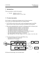
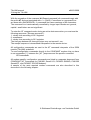
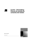
1.1 Product description
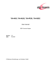
The TA+HIM is an ISDN terminal adapter with the following functions.
You can see it as a digital replacement for an analog modem.
•
The TA+HIM connects devices with a serial communication port to the ISDN.
It gives access to other devices connected to the ISDN or PSTN network .
•
Data can be transmitted either over the D- or B-channel with the following rates:
- by using the transmission method V.110 in B channel.
- by using the transmission method V.120 in B channel.
- by using the transmission method X.75 in B channel.
- by using the transmission method PPP in B channel.
- call a host connected to the X.25-network (X.25 in B or D channel).
- call a host connected to an ISDN-X.31 subscriber line
- by using analogue modem protocol in B channel:
Bell 103, Bell 212, V21, V22, V.22bis, V.23, V.32, V.32bis, V.34, V.90, V.92.
•
The connected device can drive the TA+HIM by using
- asynchronous PAD (X.3) commands
- asynchronous AT commands
TA+HIM
Modem
Serial
UART
Modem
ATHandler
DTMF
Host system 2
PSTN
Terminal
Codec
ISDN
© Stollmann Entwicklungs- und Vertriebs-GmbH
ISDN
Host
system 1
3
TA+HIM manual
2 Installation
r01/03.2008
To work with TA+HIM you need :
•
•
an ISDN Basic Rate Interface (BRI) (replacing an analogue telephone line). The
basic rate access can be ordered by your local telephone company or PTT
a PC with a terminal emulation to configure the TA+HIM
1.2 License
The TA+HIM has the following license number for the connection to the PSTN:
CE-0682 X
for Europe (EC), Switzerland, Norway.
TA+HIM is conform to the European safety requirements IEC 60 950. Connect the
TA+HIM only to the BRA-interfaces with SELV (Safety Extra Low Voltage) related to
EN60950.
The TA+HIM is conform to the European rules of EMC. EN50081-1, here EN55022
Class B, for electromagnetic field emission and EN50082-1 for emission of
electromagnetic interference.
2 Installation
2.1 Interfaces
The TA+HIM has to be accessed via 2 interface connectors:
•
•
P1:
P2:
Communication interface to control the TA+HIM and power supply
Interface to the ISDN Network
A detailed description of the interfaces is given in the appendix.
4
© Stollmann Entwicklungs- und Vertriebs-GmbH
r01/03.2008
TA+HIM manual
3 Using the TA+HIM
3 Using the TA+HIM
For the general mechanisms to use the TA+HIM please refer to the user manual for
the TA+POX / TA+HUX / TA+SOC.
The global manual describes:
• Introduction of the TA+ products
• Installation and display elements of the TA+ products
• Description of the different command sets (AT-cmd, X.3 PAD, automatic call)
• Description of the TA+Configurator command set
• Diagnostic and error messages of the TA+ products.
The following chapters will describe the differences to the TA+POX / TA+HUX /
TA+SOC and the product specific properties.
3.1 Analogue modem properties
The following section describes the functionality of using the analogue modem onto
the TA+HIM module.
The modem chip “CONEXANT CX06833-44” is placed onto the bottom side of the
TA+HIM module.
The serial interface of the modem chip is connected behind the processor system of
the TA+HIM module. Serial data commands to the modem chip needs to be sent
through the command interface of the ISDN module first.
The analogue modem interface is connected to the integrated Codec (MC 145481)
onto the TA+HIM module.
© Stollmann Entwicklungs- und Vertriebs-GmbH
5
TA+HIM manual
3 Using the TA+HIM
r01/03.2008
With the exception of the command A/ (Repeat command) all commands begin with
the prefix AT and are terminated with <↵> (0x0D). Corrections in a command line
are done with <BACKSPACE>. A command line has a maximum of 80 characters.
The command line is automatically cancelled by longer input. Blanks are ignored,
capital / small letters are not significant.
To enter the AT command mode during an active data connection you must use the
following sequence ("Escape sequence"):
1. <delay time according to S12 register>
2. <+><+><+>
3. <delay time according to S12 register>
The time gap between all three plus signs may not exceed 1 sec.
The escape sequence is transmitted transparent to the remote device.
All configuration commands are sent to the AT command interpreter of the ISDN
module (TA+HIM) as default.
To send configuration commands directly to the CONEXANT modem chip you have
to set a separator [ ! ] between the [ AT ] sequence and the specific command.
AT!<command>
All modem specific configuration commands are listed in a separate document from
CONEXANT (AT Commands for CX81801 SmartV.XX, CX06833 SMXXD, CX81300
SmartACF, and CX06827 SCXXD Modems).
A sample of the most required modem commands are also described in this
document in the following chapter.
6
© Stollmann Entwicklungs- und Vertriebs-GmbH
r01/03.2008
TA+HIM manual
3 Using the TA+HIM
3.2 Special analogue modem commands
This chapter describes special commands related to analogue modem connectivity.
The connection control to establish an active connection, accept incoming calls or
disconnect an existing connection is the same than for ISDN data connections.
An incoming analogue modem call will be accepted from the TA+HIM module
independent of the current configured B-channel protocol.
Incoming calls can suppressed when setting the incoming msn-value “AT**msni= - “.
!<command>
command prefix for onboard
CONEXANT modem configuration commands
When sending the additional <!> character between the AT prefix and the specific
configuration command the command will be transferred directly to the onboard
CONECANT modem chip.
All modem specific configuration commands are listed in a separate document from
CONEXANT (AT Commands for CX81801 SmartV.XX, CX06833 SMXXD, CX81300
SmartACF, and CX06827 SCXXD Modems).
Example:
AT!i3
AT!+MS=V32B
B
CONEXANT Modem ID
“CX81802-V90”
set modulation selection to V.32bis
B channel protocol
Transmission protocol for data communication in the B channel.
AT44 : analog
Incoming analogue calls will be accepted as modem call (ATB44) independent of
the preconfigured B-channel protocol.
© Stollmann Entwicklungs- und Vertriebs-GmbH
7
TA+HIM manual
3 Using the TA+HIM
r01/03.2008
3.3 AT commands related to the prior product “TA+HIT”
AT∗∗VMSN= <msn value>
Define own msn
Defines the msn nn (multiple subscriber number) for incoming calls “msni” and
outgoing calls “msno” for the data port.
(compare: manual TA+POX/TA+HUX/TA+SOC)
If the number is set to “*“ (default), all incoming calls are acceptable.
Both values “msni” and “msno” will be displayed by command AT&V.
AT∗∗VMSN=nn
set parameter "msni" and "msno" to nn
max. length = 20 digits
Note: If 1TR6 D channel protocol is selected, only one or the last digit is valid.
This parameter is not saved automatically.
AT∗∗VMSN needs two saving procedures. It will save the value “msni” and
“msno” separately. This parameter will not saved automatically.
ATS70=<0/1>
enable codec port for ATB40 only
This parameter enables or disables the CODEC on the TA+HIM hardware and
changes the structure of the serial data output (“:$” or “:1”).
Depending of the value in ATS70 the incoming call will message an IOM call
(:$RINGIxDxxxOxxxB0x) or a CODEC call (:1RINGIxDxxxOxxxB0x).
ATS70=0
ATS70=1
incoming call will be displayed as IOM calls (default).
Example:
:$RINGI1D211O222B01
incoming call will be displayed as CODEC calls
and enable the CODEC.
Example:
:1RINGI1D211O222B01
When the command interface receive an ext. IOM command “AT:$xxx” or an
CODEC command “AT:$xxx” the value for the data structure will be changed in this
S-register will be changed automatically.
8
© Stollmann Entwicklungs- und Vertriebs-GmbH
r01/03.2008
TA+HIM manual
3 Using the TA+HIM
3.4 B channel connection using the IOM interface
The following section describes the enhancements for driving B channel
connections through the IOM interface connector (IOM1) or the .
All other commands and behaviour, making data connection and maintaining the
module, is identical to the documentation of TA+POX and can be referenced at the
corresponding user manual.
Every command is always answered by the ISDN-module; a following command may
only be entered after a response has been received.
Every AT command that controlles a B channel connection without switching an on
board device to the B channel is preceeded by a ":" and a dummy port number
(always "$").
Example: "AT:$ CR D1234"
; Establish a connection.
Resultmessages to the commands are preceeded by ":$"
Example: ":$CONNECT..."
;Connection established
Every B channel connection is identified by a call reference "Call-Reference".
The call reference is created and reported by the ISDN module:
- incoming call: as parameter to the "RING" message
- outgoing call: as result to the "CR" command.
The call reference has to be released by the application:
- with the command "DISC".
All commands based on the same connection have to use the same call reference.
More than one call reference can be active at a time.
The B channel information is reported from the TA within the parameter Bxx.
© Stollmann Entwicklungs- und Vertriebs-GmbH
9
TA+HIM manual
3 Using the TA+HIM
r01/03.2008
Supported commands:
AT:$ A I<Call-Reference>
Accept incoming call
Using this command you can accept an incoming call, if automatic call acceptance is
not set (Register "**ATS0" = 0). An incoming call is indicated by the result message
"RING".
The Call-Reference is valid from the indication of an incomig call or the status
change of an connect request til the given release command.
Example:
"AT:$ A I1"
Accept an incoming call for port 1
AT:$ CC I<Call-Reference> D<rn..>
Send destination address to the network
Continue to send the destination address to the network (overlap dialling) after
initiating an outgoing call (i.e. command AT:$CR) without complete destination
address.
"I" selects Call-Reference, 1..9
“D” sets destination address (the dialing number).
<rn> ISDN number, string of digits, 1..22.
Example:
"AT:$ CC I1 D2"
Continue for an existing ougoing call for port 1 to send the destination
address "2" to the network.
10
© Stollmann Entwicklungs- und Vertriebs-GmbH
r01/03.2008
TA+HIM manual
3 Using the TA+HIM
AT:$ CR [D<rn..>] [O<rn..>]
Connect Request to the network
Initiate an outgoing call.
“D” sets destination address (the dialing number).
“O” sets origination address (own msn), optional.
<rn> ISDN number, string of digits, 1..22.
The TA module initiates an outgoing call request and reports the call reference.
Result message:
":$I<Call-Reference >"
Example:
Command:
Result:
"AT:$CR D234 O567"
":$I1"
Intiate an outgoing call for Port 1 with destination address 234 and
origination address 567 (own msn), the call can be referenced using the call
reference 1.
Note: The used B channel is reported via message "INFO" (option).
AT:$ CH I<Call-Reference>
Call Hold
Hold the call which is addressed by Call-Reference.
Example:
"AT:$ CH I1"
Intiate a call hold for the existing connection 1 for Port 1
AT:$ CA I<Call-Reference>
Call Retrieve
Retrieve the call which is addressed by Call-Reference
Example:
"AT:$ CA I1"
Intiate retrieve for the existing connection 1 for Port 1
© Stollmann Entwicklungs- und Vertriebs-GmbH
11
TA+HIM manual
3 Using the TA+HIM
r01/03.2008
AT:$ C3PTY I<Call-Reference> IH<Call-Reference(HeldCall)>
Pass into three party service
Pass into three party which is addressed by the call reference’s
Note: The further on used B channel is that one from the active connection.
Example:
"AT:$ C3PTY I1 IH2"
Intiate a 3 party conference.
To release a three party conference please enter the same command again, then
the previous state will be entered: Call on call reference Ixx will be active, call on
the call reference IHxx will be in hold.
If one of the other two party of the three party conference is going on hook, the
previous state for the staying connection will be entered. Example: if the previous
active connection releases the connection within the three party conference, the
three party conference will be closed and the staying connection will be in hold
state.
AT:$ #C I<Call-Reference>
Received bearer service
Shows the bearer service that is received with an incoming call in hexadecimal
coding hbhb.
The value for hbhb (word) is the CIP value as defined in the CAPI 2.0 specification.
Example:
Command
"AT:$#C I1"
Result
"0010"
; Receved bearer service
12
© Stollmann Entwicklungs- und Vertriebs-GmbH
r01/03.2008
TA+HIM manual
3 Using the TA+HIM
AT:$ DISC I<Call-Reference> [C<hb>] Disconnect
Disconnects existing ISDN connection within the given cause value hb (hexadecimal
coded byte).
The causevalue hb is defined according to Q931/ETS 300 102-1.
It is also possible to send an disconnect without an cause value (normal call
clearing).
The Call-Reference is released by this command and is no longer valid.
Example:
"AT:$ DISC I1"
Disconnect an existing connection with normal call clearing.
Example:
"AT:$ DISC I1 C11"
Disconnect an incoming call with the cause 0x11 (User busy).
AT:$ RA
I<Call-Reference>
Send alert message
Send an Alert message to the network for the call that is addressed by CallReference.
Example:
AT:$ RAI1
Initiate an alert request for an existing incoming call for port 1.
© Stollmann Entwicklungs- und Vertriebs-GmbH
13
TA+HIM manual
3 Using the TA+HIM
r01/03.2008
3.4.1 AT result messages
All messages sent from the codec port of the TA+HIM are preceeded by an ":$".
There are no spaces between the different parameters of the messages.
:$ CONNECT I<Call-Reference> D<rn..> O<rn..> B<hb>
Connection established
Indicates that the connection with the remote side is established using CallReference.
“D” shows destination address (the dialled number).
“O” shows origination address (the dialling number).
“B” shows B channel used (hexadecimal coded byte):
01 = B channel 1 occupied.
02 = B channel 2 occupied.
<rn> ISDN number, string of digits, 1..22.
Example:
":$CONNECTI1D234O567B01"
Indicates a connection for Port 1 with destination address 234 and origination
address 567 and using B channel 1.
:$ DISC I<Call-Reference> C<hbhb>
disconnect received
Indicates that a call has been disconnected.
The cause is indicated with causevalue hb (hexadecimal coded word).
The causevalue hb is defined according to CAPI 2.0 (see also TA+POX manual
CAPI-causes).
Example:
":$DISCI1C3491"
Outgoing call is cleared with the ISDN cause 0x91 (User busy).
:$ INFO I<Call-Reference> D<rn..>
information to existing call reference
Information initated by a status change for an existing call reference with:
“D” shows destination address (the dialled number).
Example:
14
":$INFO I1D9"
next dialled number "9" received.
© Stollmann Entwicklungs- und Vertriebs-GmbH
r01/03.2008
TA+HIM manual
3 Using the TA+HIM
:$ INFO I<Call-Reference> B<hb>
information to existing call reference
Information initated by a status change for an existing call refence with:
“B” shows B channel used (hexadecimal coded byte):
00 = no B channel occupied.
01 = B channel 1 occupied.
02 = B channel 2 occupied.
Example:
":$INFO I1B01"
:$ RING I<Call-Reference> D<rn..> O<rn..> B<hb>
incoming call
Indicates an incoming call, a SETUP is received.
“D” shows destination address (the dialled number, = dialled msn).
“O” shows origination address (the dialling number).
“B” shows B channel used (hexadecimal coded byte):
00 = no B channel occupied (if call waiting and both B channels
occupied).
01 = B channel 1 occupied.
02 = B channel 2 occupied.
<rn> ISDN number, string of digits, 1..22.
Example:
":$RINGI1D234O567B01"
Indicates an incoming call for port 1 with destination address 234 and
origination address 567 and using B channel 1.
Note: This message is repeated (like in AT modems).
:$ CRA I<Call-Reference>
call request accepted
Indicates that the call request is accepted.
Example:
":$CRAI1"
© Stollmann Entwicklungs- und Vertriebs-GmbH
15
TA+HIM manual
3 Using the TA+HIM
:$ RINGING I<Call-Reference>
r01/03.2008
called party is ringing
Indicates that the call request is accepted at the called party and a ringing is issued.
Example:
":$RINGINGI1"
Note: This message is not repeated (like in AT modems).
16
© Stollmann Entwicklungs- und Vertriebs-GmbH
r01/03.2008
TA+HIM manual
3 Using the TA+HIM
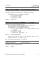
3.4.2 Call control examples
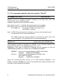
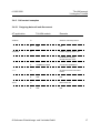
3.4.2.1 Outgoing data call and disconnect
AT application
"ATB10"
TA+HIM module
à
ß
“ATD123”
Remarks
Select b-channel protocol
“OK“
à
OK
Initiate outgoing call to 123
Destination is ringing,
accept call with “ATA”
ß
“+++”
à
ß
“ATH”
“CONNECT 64000“
Change into local command
mode
“OK”
à
ß
Connection established
OK
Disconnect call
“OK”
© Stollmann Entwicklungs- und Vertriebs-GmbH
OK
17
TA+HIM manual
3 Using the TA+HIM
r01/03.2008
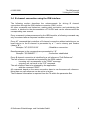
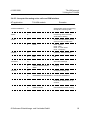
3.4.2.2 Outgoing voice call and disconnection over IOM interface
AT application
"ATB40"
TA+HIM module
à
ß
Remarks
Select ext. IOM connection
“OK“
OK
“AT:$CRD123” à
Initiate outgoing call to 123
ß
“:$CRAI1B01“
Call request accepted
ß
“:$RINGINGI1”
Destination is ringing
Destination accept call
ß
“:$CONNECTI1D123O234B01“ Connection established
“AT:$DISCI1” à
18
Disconnect call
ß
":$OK"
OK
ß
":$RELI1C”
Call released
© Stollmann Entwicklungs- und Vertriebs-GmbH
r01/03.2008
TA+HIM manual
3 Using the TA+HIM
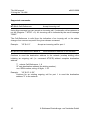
3.4.2.3 Accepted incoming voice call over IOM interface
AT application
TA+HIM module
Remarks
“AT#C2=00000001”
à
Select bearer service incomming,
accept all incomming calls
“RING”
ß
Incomming call to TA+HIM,
destination is dialling
“AT#C”
à
Check received bearer service,
select for voice or data calls
ß
"ATB40"
à
ß
“AT:$RAI1”
“OK“
OK
Send alert message
“:$RINGI1D300O310B01“
“:$OK“
à
ß
0001 : Speech
0002 : Data
0004 : 3,1 kHz Audio
0010 : Telephony
Select ext. IOM connection
à
ß
ß
“AT:$AI1”
“0004“
Ringing
Accept incomming call
“:$CONNECTI1D123O234B01“ Connection established
Destination disconnect, i.e. go
onhook
ß
":$RELI1C3490”
© Stollmann Entwicklungs- und Vertriebs-GmbH
Call released, normal clearing
19
TA+HIM manual
3 Using the TA+HIM
r01/03.2008
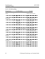
3.4.2.4 Call hold handling
AT application
TA+HIM module
à
"ATB40"
ß
Select ext. IOM connection
“OK“
OK
à
“AT:$CRD123”
Remarks
Initiate outgoing call to 123
ß
“:$CRAI1B01“
Call request accepted
ß
“:$RINGINGI1”
Destination is ringing
Destination accept call
ß
à
“AT:$CHI1”
ß
ß
20
Put activ connection in hold
“:$HOLDI1”
à
“AT:$CAI1”
“AT:$DISCI1”
“:$CONNECTI1D123O234B01“ Connection established
Connection I1 is in hold
Retreive the hold connection
“:$OK”
à
OK
Disconnect call
ß
":$OK"
OK
ß
":$RELI1C”
Call released
© Stollmann Entwicklungs- und Vertriebs-GmbH
r01/03.2008
TA+HIM manual
3 Using the TA+HIM
3.5 Using TA+HIM with DTMF detection
This commands enables the DTMF recognizing mechanism for DTMF signals on the
B channel from the ISDN line (AT**RCVDTMF=1).
The DTMF recognition is valid on the serial interface if B channel protocol is set to
transparent (ATB5) or over the external IOM interface with the B channel protocol
ATB40. The presentation of received data should be disabled (AT**RCVDATA=0).
Detected and valid received DTMF signals are presented via the V.24 interface
using the following syntax inside the V.24 data stream.
RCVDATA
Disable receiving B channel data
This command disables the presentation of B channel data received from the ISDN
line via the V.24 interface.
AT**RCVDATA=0 disable receive data from the ISDN line
AT**RCVDATA=1 enable receive data from the ISDN line
RCVDTMF
Enable interpretation of DTMF signals
(only valid for ATB5)
AT**RCVDTMF=0 disable DTMF recognition
AT**RCVDTMF=1 enable DTMF recognition
The received DTMF tones are presented in the following way:
<DLE> 1
key “1” pressed by the connected phone
<DLE> 2
key “2” pressed by the connected phone
<DLE> x
key “0, … 9” pressed by the connected phone
<DLE> *
key “*” pressed by the connected phone
<DLE> #
key “#” pressed by the connected phone
<DLE> is presented as hex value 0x10.
© Stollmann Entwicklungs- und Vertriebs-GmbH
21
TA+HIM manual
4 Appendix
r01/03.2008
4 Appendix
A1:
Technical data TA+HIM
One serial channel for data communication and connection control:
functional:
V.24
electrical:
TTL
mechanical:
dual pin rows
one audio interface for voice:
input:
output:
Data transmission speeds:
DTE:
B channel:
Modem:
typical 750 mVpp
typical 750 mVpp , RL > 2000 Ohm
1200 – 230400 bit/s (asynchronous)
2 x 64000 bit/s (synchronous)
Bell 103, Bell 212, V21, V22, V.22bis, V.23, V.32,
V.32bis, V.34, V.90, V.92
Character representation:
8Bit no Parity, 1 stop bit
7Bit even/odd Parity, 1 stop bit
Character synchronization:
asynchronous
Operating mode:
half duplex or full duplex
ISDN interface:
BRA-interface according to ITU I.430
Power supply:
+5V ∀5%,
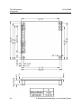
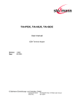
Physical dimensions:
plug on module: 56 x 56 x 12 (8) mm (WxDxH)
22
nominal: app. 60 mA, (max 110 mA)
idle: app. 25 mA.
© Stollmann Entwicklungs- und Vertriebs-GmbH
r01/03.2008
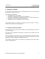
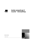
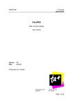
A2:
TA+HIM manual
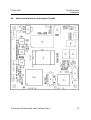
4 Appendix
Mechanical dimensions of the module TA+HIM
© Stollmann Entwicklungs- und Vertriebs-GmbH
23
TA+HIM manual
4 Appendix
r01/03.2008
.
24
© Stollmann Entwicklungs- und Vertriebs-GmbH
r01/03.2008
TA+HIM manual
4 Appendix
A3: TA+HIM Serial Interface Connector P1
P1-Pin
Signal
Direction TA usage
from
TA+HIM
1
GND
I
0V-Power
GND
0V
supply
+5V
supply
GND
GND
GND
GND on TA+HIM
NC or READ
10k Pull up on TA+HIM
NC or READ
RESET active low OC
NC
2
VCC
3
4
5
6
7
8
9
10
11
12
13
GND
TXD
GND
RXD
ID2
RTS
ID1
CTS
RESET
DTR
L3
O
O
I
O
O
I
I
O
14
15
16
17
DCD
RI
DSR
UA
O
O
O
O
User Output 1
18
19
20
UE
UA2
UE2
I
O
I
User Input 1
User Output 2
User Input 2
A4:
I
External
interfacing
+5V-Power
Power
Power
I
NC
info
TA+HIM ISDN interface Connector P2
P2-Pin
Signal
Direction
1
RXI
2
TXO
3
RX+
I
4
TX+
O
5
RX (BRA-power
O
supply)
6
TX (BRA-power
O
supply)
© Stollmann Entwicklungs- und Vertriebs-GmbH
or
status
NC or status
info
NC, reserved
NC, reserved
NC, reserved
RJ-45-Pin
5
6
4
3
NC
NC
25
TA+HIM manual
4 Appendix
r01/03.2008
A5: TA+HIM interface Connector IOM1 (option)
IOM1-Pin
Signal
Direction from
TA usage
TA
1
DD
O
IOM Data downstream
2
DU
I
IOM Data upstream
3
FSC
O
IOM frame sync
4
DCL
O
IOM double bit clock
5
SDS
O
IOM B channel strobe
6
BCL
O
IOM bit clock
A6: TA+HIM interface Connector JTAG1 (option)
Signal
TA usage
JTAG1-Pin
1
TDI
Serial data in
2
TDO
Serial data out
3
TMS
TAP mode select
4
RES
Target System reset
5
TCK
Clock
6
GND
Signal Ground
7
TRST
TAP reset
8
VCC
3,3 V
A7:
A8:
26
TA+HIM serial interface Connector S2 (option)
S2-Pin
Signal
Direction
1
NC
2
TXD
I
3
GND
4
RXD
O
Pinout of the ISDN S-interface connector (RJ45) (CCITT I.430/ISO 8877)
Pin
Signal (BRA)
1
Not connected
2
Not connected
3
Tx+ (Transmit +)
4
Rx+ (Receive +)
5
Rx- (Receive -)
6
Tx- (Transmit -)
7
Not connected
8
Not connected
© Stollmann Entwicklungs- und Vertriebs-GmbH